EP2312702A1 - Netzanschlussstecker für ein Haushaltsgerät, Haushaltsgerät und Verfahren zum Zuschalten und Abkoppeln eines in einem Haushaltsgerät angeordneten Bauteils mittels eines Schalters - Google Patents
Netzanschlussstecker für ein Haushaltsgerät, Haushaltsgerät und Verfahren zum Zuschalten und Abkoppeln eines in einem Haushaltsgerät angeordneten Bauteils mittels eines Schalters Download PDFInfo
- Publication number
- EP2312702A1 EP2312702A1 EP10183745A EP10183745A EP2312702A1 EP 2312702 A1 EP2312702 A1 EP 2312702A1 EP 10183745 A EP10183745 A EP 10183745A EP 10183745 A EP10183745 A EP 10183745A EP 2312702 A1 EP2312702 A1 EP 2312702A1
- Authority
- EP
- European Patent Office
- Prior art keywords
- power connector
- switch
- household appliance
- domestic appliance
- electrical component
- Prior art date
- Legal status (The legal status is an assumption and is not a legal conclusion. Google has not performed a legal analysis and makes no representation as to the accuracy of the status listed.)
- Granted
Links
Images


Classifications
-
- H—ELECTRICITY
- H01—ELECTRIC ELEMENTS
- H01R—ELECTRICALLY-CONDUCTIVE CONNECTIONS; STRUCTURAL ASSOCIATIONS OF A PLURALITY OF MUTUALLY-INSULATED ELECTRICAL CONNECTING ELEMENTS; COUPLING DEVICES; CURRENT COLLECTORS
- H01R13/00—Details of coupling devices of the kinds covered by groups H01R12/70 or H01R24/00 - H01R33/00
- H01R13/66—Structural association with built-in electrical component
- H01R13/70—Structural association with built-in electrical component with built-in switch
- H01R13/703—Structural association with built-in electrical component with built-in switch operated by engagement or disengagement of coupling parts, e.g. dual-continuity coupling part
- H01R13/7031—Shorting, shunting or bussing of different terminals interrupted or effected on engagement of coupling part, e.g. for ESD protection, line continuity
-
- H—ELECTRICITY
- H01—ELECTRIC ELEMENTS
- H01R—ELECTRICALLY-CONDUCTIVE CONNECTIONS; STRUCTURAL ASSOCIATIONS OF A PLURALITY OF MUTUALLY-INSULATED ELECTRICAL CONNECTING ELEMENTS; COUPLING DEVICES; CURRENT COLLECTORS
- H01R13/00—Details of coupling devices of the kinds covered by groups H01R12/70 or H01R24/00 - H01R33/00
- H01R13/66—Structural association with built-in electrical component
- H01R13/70—Structural association with built-in electrical component with built-in switch
- H01R13/713—Structural association with built-in electrical component with built-in switch the switch being a safety switch
-
- H—ELECTRICITY
- H01—ELECTRIC ELEMENTS
- H01R—ELECTRICALLY-CONDUCTIVE CONNECTIONS; STRUCTURAL ASSOCIATIONS OF A PLURALITY OF MUTUALLY-INSULATED ELECTRICAL CONNECTING ELEMENTS; COUPLING DEVICES; CURRENT COLLECTORS
- H01R2103/00—Two poles
-
- H—ELECTRICITY
- H01—ELECTRIC ELEMENTS
- H01R—ELECTRICALLY-CONDUCTIVE CONNECTIONS; STRUCTURAL ASSOCIATIONS OF A PLURALITY OF MUTUALLY-INSULATED ELECTRICAL CONNECTING ELEMENTS; COUPLING DEVICES; CURRENT COLLECTORS
- H01R24/00—Two-part coupling devices, or either of their cooperating parts, characterised by their overall structure
- H01R24/28—Coupling parts carrying pins, blades or analogous contacts and secured only to wire or cable
- H01R24/30—Coupling parts carrying pins, blades or analogous contacts and secured only to wire or cable with additional earth or shield contacts
Definitions
- the invention relates to a power connector for a household appliance with a switch that opens or closes depending on whether the power connector is inserted into a power outlet.
- the invention further relates to the household appliance with such a power connector.
- the invention also relates to a method for selectively connecting and disconnecting an electrical component arranged in a domestic appliance by means of a switch.
- a typical line filter has capacitors and a discharge resistor.
- Discharge resistance on electrical appliances with a mains plug serves to quickly discharge the capacitors in a grid disconnect so that a residual voltage on the power plug is not hazardous to a user.
- the discharge resistor often has the disadvantage that it generates a power loss due to the current flowing through it during normal operation and also in standby mode.
- the line filter is disconnected.
- part of the filter usually the discharge resistor, only switched on when needed, switching usually takes place via a relay.
- the discharge resistor is disconnected from the mains voltage as long as the connection to the supply network is not interrupted, e.g. by pulling the power connector. It is disadvantageous that the relay has a comparatively long switching delay.
- An accommodation of the discharge resistor and a switch for connecting and disconnecting the discharge resistor in the power connector is advantageous because the switch can switch significantly less delay than the present in the household appliance relay.
- the disadvantage is that the power connector on the built-in discharge resistor and consequently to the net filter used specifically in the household appliance.
- Such a power connector is eg in EP 1 605 556 A1 shown.
- a power connector for a household appliance which has a switch that opens or closes depending on whether the power connector is inserted into a power outlet.
- the switch is connected on the one hand to a power supply line and on the other hand to a first auxiliary line (i.e., a first additional line for power supply) leading from the mains connector.
- the switch can thus turn on and off the first auxiliary line.
- the power connector has a fast-switching switch and on the other hand, no electrical component, which is specially adapted to the household appliance as such, so that the power connector can be used without further adjustment with different household appliances.
- at least one electrical component arranged or installed in the household appliance can be switched by the switch.
- the to be switched at least one electrical component is connected to the first additional line instead of the supply line to which the switch is connected.
- the switching to at least one electrical component is then connected only via the switch with the supply line (outer conductor or neutral conductor).
- the power supply line may be e.g. an outer conductor or a neutral conductor.
- the switch may be open or closed in the case of the power connector plug inserted into the socket, and vice versa be closed or open at the power connector removed from the socket.
- the switch opens in the event that the mains plug is inserted into the socket, and in the event that the power connector is at least partially removed from the socket closes.
- a discharge resistor or any other electrical component can be switched on or connected, which should fulfill its function only in a separate network connection.
- the power supply line is an outer conductor.
- the power connector has a second auxiliary line, which leads from the power connector and which directly to the other of the power supply lines, which is not connected to the switch, in particular to a neutral conductor connected.
- the device to be switched can then be connected to the two additional lines instead of the conventional supply lines.
- five-core cables can be used, which are more common in power supply cables than four-core cables.
- the switch has a movable projection which can be moved out of a front side of a housing of the mains connection plug, the switch being switched by a movement of the projection. This allows a simple and safe circuit of the switch can be achieved when inserting or removing the power connector.
- the object is also achieved by a household appliance, wherein the household appliance is equipped with such a power connector.
- At least the first additional line is connected to at least one electrical component arranged in the household appliance.
- the at least one electrical component can be switched substantially instantaneously, although it is located in the household appliance or its housing.
- the electrical component arranged in the domestic appliance is a mains filter or a part of a mains filter.
- a delay-free circuit of the network filter e.g. for a discharge of the capacitors to be achieved
- the electrical component arranged in the domestic appliance is a discharge resistor of the mains filter.
- a delay-free discharge of the capacitors of the mains filter can be achieved and at the same time a power loss can be prevented with plugged power connector via the discharge resistor.
- the discharge resistor is connected to the first additional line and to the second additional line.
- the discharge resistor is connected to the first additional line and to the second additional line.
- two wires of five-wire cables can be used, which are more common in power supply cables than four-core cables.
- the object is also achieved by a method for selectively connecting and disconnecting at least one arranged in a household appliance electrical component by means of a switch, wherein the switch is housed in a power connector of the household appliance and is connected by plugging in and removing the power connector. This also allows the at least one electrical component to be switched quickly without having to tune the power connector to the home appliance.
- the electrical component is a discharge resistor of a mains filter and is switched off when the power connector is plugged in and is switched on when the power connector is unplugged.
- the method can, inter alia, be developed analogously to the variants of the devices listed above.
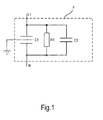
- Fig.1 shows a circuit diagram of a conventional network filter F, which is connected within an electrical device between an outer conductor L1 and a neutral conductor N.
- the line filter F shown here has three components connected in parallel, namely a first capacitor C1, a discharge resistor R1 and a second capacitor C2.
- the first capacitor C1 may be configured as a pair of series-connected Y capacitors with a grounded center tap.
- Line filters are well known to those skilled in the art and are available in a number of different embodiments, which may include more and / or different components than those shown here for the line filter F.
- the discharge resistor R1 serves to discharge the capacitors C1 and C2 so quickly after an interruption of the mains connection that a user does not receive a significant electric shock by these capacitors C1, C2.
- the discharge resistor R1 can be dimensioned such that one second after the grid disconnection, a maximum voltage of 34 volts is applied to the capacitors C1, C2.
- Fig.2 shows a circuit sketch and Figure 4 shows a construction diagram of a power connector 1 according to the invention, which as conventional has the outer conductor L1 and the neutral conductor N as the two supply lines and a protective conductor PE.
- the outer conductor L1 and the neutral conductor N have as contacts in each case a contact pin 2 or 3, while the protective contact 4 of the protective conductor PE rests on a housing of the power connector 1, for example a Schuko plug.
- the power connector 1 is further equipped with a switch S1, which is electrically connected to one side with the outer conductor L1 and the other side with a first auxiliary line A, which leads from the power connector 1 is connected.
- the switch S1 thus turns on and off the first auxiliary line A.
- the switch S1 has a movable projection 6, which protrudes from a front side of the mains connector 1 when the mains connector 1 is pulled in and is pressed into the mains connector 1 when the mains connector 1 is inserted.
- the switch S1 is closed, and when the power connector 1 is inserted, the projection 6 keeps the switch S1 open. From the power connector 1 thus lead in addition to the known supply lines L1 and N and the protective conductor PE, the two additional lines A and B, the first auxiliary line A acts as a switch S1 through the switch substantially delay and off and the second additional line B how the neutral conductor N acts.
- FIG 3 shows an electrical appliance in the form of a household appliance H with the power connector 1.
- the household appliance H has, inter alia, a line filter F2, in which, in contrast to the conventional line filter F off Fig.1 the discharge resistor R1 is connected to the two auxiliary lines A and B, while the remaining elements of the network filter F2, here: the two capacitors C1 and C2, are connected to the outer conductor L1 and the neutral conductor N. Since the neutral conductor N and the second additional line B are directly electrically connected to each other and thus have substantially the same function and effect, the discharge resistor R1 may be arranged electrically in an alternative embodiment, also between the first auxiliary line A and the neutral conductor N.
- the switch S1 is opened when the mains connector 1 is inserted, so that the discharge resistor R1 is disconnected from the line filter F2. It can thus be prevented in a powered household appliance H a loss of conduction to the discharge resistor R1.
- the switch S1 When the power connector 1 is removed, the switch S1 is closed, so that the discharge resistor R1 is connected to the line filter F2. At the same time as the power supply to the household appliance H is interrupted, the voltage applied to the capacitors C1, C2 voltage can be reduced by flowing a corresponding discharge current through the discharge resistor R1. This is done essentially immediately with pulling the power connector 1 and switching the switch S1.
- the power connector can dispense with the second additional line B, for example. Accordingly, the discharge resistor (or any other electrical component provided for switching through the switch S1) may be electrically inserted between the first auxiliary line A and the neutral conductor N.
- the switch S1 may be connected to the neutral conductor instead of the outer conductor.
- the household appliance may be, for example, a microwave oven, a refrigerator, a dishwasher, a small household appliance, etc.
Landscapes
- Details Of Connecting Devices For Male And Female Coupling (AREA)
Abstract
Description
- Die Erfindung betrifft einen Netzanschlussstecker für ein Haushaltsgerät mit einem Schalter, der abhängig davon, ob der Netzanschlussstecker in eine Steckdose eingesetzt ist, öffnet oder schließt. Die Erfindung betrifft ferner das Haushaltsgerät mit einem solchen Netzanschlussstecker. Die Erfindung betrifft außerdem ein Verfahren zum wahlweisen Zuschalten und Abkoppeln eines in einem Haushaltsgerät angeordneten elektrischen Bauteils mittels eines Schalters.
- Viele Elektrogeräte weisen Netzfilter auf, von denen es verschiedene Varianten gibt. Ein typisches Netzfilter weist Kondensatoren und einen Entladewiderstand auf. Der Entladewiderstand dient bei Elektrogeräten mit einem Netzanschlussstecker (z.B. einem Schuko-Stecker) dazu, bei einer Netztrennung die Kondensatoren schnell zu entladen, so dass eine Restspannung an dem Netzanschlussstecker für einen Benutzer nicht gefährlich ist. Der Entladewiderstand weist jedoch häufig den Nachteil auf, dass er durch den durch ihn fließenden Strom im Normalbetrieb und auch im Standby-Betrieb eine Verlustleistung erzeugt.
- Um eine niedrige Verlustleistung, insbesondere einen niedrigen Standby-Verbrauch, zu erzielen, wird derzeit das Netzfilter aufgetrennt. Dabei wird ein Teil des Filters, meist der Entladewiderstand, nur bei Bedarf zugeschaltet, das Schalten findet meist über ein Relais statt. Der Entladewiderstand ist dabei von der Netzspannung abgetrennt, solange die Verbindung zu dem Versorgungsnetz nicht unterbrochen ist, z.B. durch ein Ziehen des Netzanschlusssteckers. Dabei ist nachteilig, dass das Relais eine vergleichsweise lange Schaltverzögerung aufweist.
- Eine Unterbringung des Entladewiderstands und eines Schalters zum Zuschalten und Abkoppeln des Entladewiderstands in dem Netzanschlussstecker ist vorteilhaft, da der Schalter erheblich verzögerungsfreier schalten kann als das in dem Haushaltsgerät vorhandene Relais. Nachteilig ist, dass der Netzanschlussstecker auf den verbauten Entladewiderstand und folglich auf das speziell in dem Haushaltsgerät verwendete Netzfilter festgelegt ist. Ein solcher Netzanschlussstecker ist z.B. in
EP 1 605 556 A1 gezeigt. - Es ist die Aufgabe der vorliegenden Erfindung, die genannten Nachteile des Standes der Technik zumindest teilweise zu vermeiden und insbesondere eine Möglichkeit zum verzögerungsfreieren Schalten von elektrischen Bauelementen mittels eines Netzanschlusssteckers bereitzustellen, welcher im Wesentlichen geräteunabhängig einsetzbar ist.
- Diese Aufgabe wird gemäß den Merkmalen der unabhängigen Ansprüche gelöst. Bevorzugte Ausführungsformen sind insbesondere den abhängigen Ansprüchen entnehmbar.
- Die Aufgabe wird gelöst durch einen Netzanschlussstecker für ein Haushaltsgerät, welcher einen Schalter aufweist, der abhängig davon, ob der Netzanschlussstecker in eine Steckdose eingesetzt ist, öffnet oder schließt. Der Schalter ist einerseits mit einer Stromversorgungsleitung und andererseits mit einer ersten Zusatzleitung (d.h., einer ersten zusätzlichen Leitung zur Stromversorgung), welche aus dem Netzanschlussstecker führt, verbunden. Der Schalter kann somit die erste Zusatzleitung einschalten und ausschalten.
- Dadurch weist der Netzanschlussstecker einen schnell schaltenden Schalter auf und andererseits kein elektrisches Bauelement, welches auf das Haushaltsgerät als solches speziell abgestimmt ist, so dass der Netzanschlussstecker ohne eine weitere Anpassung mit unterschiedlichen Haushaltsgeräten verwendet werden kann. Durch den Schalter kann insbesondere mindestens ein in dem Haushaltsgerät angeordnetes oder verbautes elektrisches Bauteil geschaltet werden. Das zu schaltende mindestens eine elektrische Bauteil ist statt mit der Versorgungsleitung, mit welcher der Schalter verbunden ist, mit der ersten Zusatzleitung verbunden. Das zu schaltende mindestens eine elektrische Bauteil ist dann nur über den Schalter mit der Versorgungsleitung (Außenleiter oder Neutralleiter) verbunden.
- Die Stromversorgungsleitung kann z.B. ein Außenleiter oder ein Neutralleiter sein.
- Der Schalter kann bei dem in die Steckdose eingesetzten Netzanschlussstecker je nach Ausführung geöffnet sein oder geschlossen sein und umgekehrt bei dem aus der Steckdose entfernten Netzanschlussstecker geschlossen sein bzw. geöffnet sein.
- Es ist eine Ausgestaltung, dass der Schalter für den Fall, dass der Netzanschlussstecker in die Steckdose eingesetzt ist, öffnet und für den Fall, dass der Netzanschlussstecker zumindest teilweise aus der Steckdose abgezogen ist, schließt. Dadurch kann insbesondere ein Entladewiderstand oder jedes andere elektrische Bauelement eingeschaltet oder verbunden werden, welches seine Funktion erst bei einer getrennten Netzanbindung erfüllen soll.
- Es ist eine für einen besonders sicheren Betrieb bevorzugte Ausgestaltung, dass die Stromversorgungsleitung ein Außenleiter ist.
- Es ist noch eine weitere Ausgestaltung, dass der Netzanschlussstecker eine zweite Zusatzleitung aufweist, welche aus dem Netzanschlussstecker führt und welche direkt an die andere der Stromversorgungsleitungen, welche nicht mit dem Schalter verbunden ist, insbesondere an einen Neutralleiter, angeschlossen ist. Das zu schaltende Bauelement kann dann statt mit den herkömmlichen Versorgungsleitungen mit den beiden Zusatzleitungen verbunden sein. Dadurch können beispielsweise fünfadrige Leitungen verwendet werden, welche bei Netzanschlussleitungen häufiger vorhanden sind als vieradrige Leitungen.
- Es ist ferner eine Ausgestaltung, dass der Schalter einen aus einer Vorderseite eines Gehäuses des Netzanschlusssteckers herausfahrbaren beweglichen Vorsprung aufweist, wobei durch eine Bewegung des Vorsprungs der Schalter geschaltet wird. Dadurch kann eine einfache und sichere Schaltung des Schalters bei Einsetzen oder Entfernen des Netzanschlusssteckers erreicht werden.
- Die Aufgabe wird auch gelöst durch ein Haushaltsgerät, wobei das Haushaltsgerät mit einem solchen Netzanschlussstecker ausgestattet ist.
- Es ist eine Ausgestaltung, dass zumindest die erste Zusatzleitung mit mindestens einem in dem Haushaltsgerät angeordneten elektrischen Bauteil verbunden ist. Dadurch kann das mindestens eine elektrische Bauteil im Wesentlichen verzögerungsfrei geschaltet werden, obwohl es sich in dem Haushaltsgerät bzw. dessen Gehäuse befindet.
- Es ist eine weitere Ausgestaltung, dass das in dem Haushaltsgerät angeordnete elektrische Bauteil ein Netzfilter oder ein Teil eines Netzfilters ist. So kann eine verzögerungsfreie Schaltung des Netzfilters, z.B. für eine Entladung der Kondensatoren, erreicht werden
- Es ist noch eine weitere Ausgestaltung, dass das in dem Haushaltsgerät angeordnete elektrische Bauteil ein Entladewiderstand des Netzfilters ist. So kann eine verzögerungsfreie Entladung der Kondensatoren des Netzfilters erreicht werden und gleichzeitig eine Verlustleistung bei eingestecktem Netzanschlussstecker über den Entladewiderstand verhindert werden.
- Es ist auch eine Ausgestaltung, dass der Entladewiderstand an die erste Zusatzleitung und an die zweite Zusatzleitung angeschlossen ist. Hierzu können beispielsweise zwei Adern von fünfadrigen Leitungen verwendet werden, welche bei Netzanschlussleitungen häufiger vorhanden sind als vieradrige Leitungen.
- Die Aufgabe wird auch gelöst durch ein Verfahren zum wahlweisen Zuschalten und Abkoppeln mindestens eines in einem Haushaltsgerät angeordneten elektrischen Bauteils mittels eines Schalters, wobei der Schalter in einem Netzanschlussstecker des Haushaltsgeräts untergebracht ist und durch ein Einstecken und Entfernen des Netzanschlusssteckers geschaltet wird. Auch hierdurch kann das mindestens eine elektrische Bauteil schnell geschaltet werden, ohne den Netzanschlussstecker auf das Haushaltsgerät abstimmen zu müssen.
- Es ist eine Weiterbildung, dass das elektrische Bauteil ein Entladewiderstand eines Netzfilters ist und bei eingestecktem Netzanschlussstecker ausgeschaltet ist und bei ausgestecktem Netzanschlussstecker eingeschaltet ist.
- Das Verfahren kann unter anderem analog zur den Varianten der oben aufgeführten Vorrichtungen weitergebildet werden.
- In den folgenden Figuren wird die Erfindung anhand eines Ausführungsbeispiels schematisch genauer beschrieben. Dabei können zur Übersichtlichkeit gleiche oder gleichwirkende Elemente mit gleichen Bezugszeichen versehen sein.
- Fig.1
- zeigt eine Schaltskizze eines herkömmlichen Netzfilters zur Verwendung in einem Elektrogerät;
- Fig.2
- zeigt eine Schaltskizze eines erfindungsgemäßen Netzanschlusssteckers;
- Fig.3
- zeigt ein Haushaltsgerät mit dem erfindungsgemäßen Netzanschlussstecker; und
- Fig.4
- zeigt eine Aufbauskizze des erfindungsgemäßen Netzanschlusssteckers.
-
Fig.1 zeigt eine Schaltskizze eines herkömmlichen Netzfilters F, welches innerhalb eines Elektrogeräts zwischen einen Außenleiter L1 und einen Neutralleiter N geschaltet ist. Das gezeigte Netzfilter F weist hier drei parallel geschaltete Komponenten auf, nämlich einen ersten Kondensator C1, einen Entladewiderstand R1 und einen zweiten Kondensator C2. Der erste Kondensator C1 kann beispielsweise als ein Paar von in Reihe geschalteten Y-Kondensatoren mit einem geerdeten Mittenabgriff ausgestaltet sein. Netzfilter sind dem Fachmann gut bekannt und in einer Reihe verschiedener Ausführungsformen erhältlich, welche mehr und/oder andere Komponenten als die hier für das Netzfilter F gezeigten aufweisen können. - Der Entladewiderstand R1 dient dazu, die Kondensatoren C1 und C2 nach einer Unterbrechung des Netzanschlusses so schnell zu entladen, dass ein Benutzer durch diese Kondensatoren C1, C2 keinen wesentlichen Stromschlag erhält. Beispielsweise kann der Entladewiderstand R1 so dimensioniert sein, dass eine Sekunde nach der Netztrennung eine maximale Spannung von 34 Volt an den Kondensatoren C1, C2 anliegt.
-
Fig.2 zeigt eine Schaltskizze undFig.4 zeigt eines Aufbauskizze eines erfindungsgemäßen Netzanschlusssteckers 1, welcher wie herkömmlich den Außenleiter L1 und den Neutralleiter N als die beiden Versorgungsleitungen und einen Schutzleiter PE aufweist. Der Außenleiter L1 und der Neutralleiter N weisen als Kontakte jeweils einen Kontaktstift 2 bzw. 3 auf, während der Schutzkontakt 4 des Schutzleiters PE auf einem Gehäuse des Netzanschlusssteckers 1 aufliegt, z.B. eines Schuko-Steckers. - Der Netzanschlussstecker 1 ist ferner mit einem Schalter S1 ausgerüstet, der mit einer Seite mit dem Außenleiter L1 elektrisch verbunden ist und der mit seiner anderen Seite mit einer ersten Zusatzleitung A, welche aus dem Netzanschlussstecker 1 führt, verbunden ist. Der Schalter S1 schaltet somit die erste Zusatzleitung A ein und aus. Von dem Neutralleiter N zweigt eine zweite Zusatzleitung B ab, welche ebenfalls aus dem Netzanschlussstecker 1 führt.
- Der Schalter S1 weist einen beweglichen Vorsprung 6 auf, welcher bei gezogenem Netzanschlussstecker 1 aus einer Vorderseite des Netzanschlusssteckers 1 ragt und bei eingesetztem Netzanschlussstecker 1 in den Netzanschlussstecker 1 eingedrückt ist. Bei gezogenem Netzanschlussstecker 1 ist der Schalter S1 geschlossen, und bei eingesetztem Netzanschlussstecker 1 hält der Vorsprung 6 den Schalter S1 offen. Aus dem Netzanschlussstecker 1 führen somit zusätzlich zu den bekannten Versorgungsleitungen L1 1 und N und dem Schutzleiter PE die beiden Zusatzleitungen A und B, wobei die erste Zusatzleitung A wie ein durch den Schalter S1 im Wesentlichen verzögerungslos ein- und ausschaltbarer Außenleiter wirkt und die zweite Zusatzleitung B wie der Neutralleiter N wirkt.
-
Fig.3 zeigt ein Elektrogerät in Form eines Haushaltsgeräts H mit dem Netzanschlussstecker 1. Das Haushaltsgerät H weist unter anderem ein Netzfilter F2 auf, bei welchem im Gegensatz zu dem herkömmlichen Netzfilter F ausFig.1 der Entladewiderstand R1 an die beiden Zusatzleitungen A und B angeschlossen ist, während die restlichen Elemente des Netzfilters F2, hier: die beiden Kondensatoren C1 und C2, an den Außenleiter L1 und den Neutralleiter N angeschlossen sind. Da der Neutralleiter N und die zweite Zusatzleitung B direkt miteinander elektrisch verbunden sind und somit im Wesentlichen die gleiche Funktion und Wirkung besitzen, kann der Entladewiderstand R1 in einer alternativen Ausgestaltung auch zwischen der ersten Zusatzleitung A und dem Neutralleiter N elektrisch angeordnet sein. - Bei dem gezeigten Ausführungsbeispiel ist bei eingesetztem Netzanschlussstecker 1 der Schalter S1 geöffnet, so dass der Entladewiderstand R1 von dem Netzfilter F2 getrennt ist. Es kann somit bei einem mit Strom versorgten Haushaltsgerät H eine Verlustleitung an dem Entladewiderstand R1 verhindert werden.
- Bei entferntem Netzanschlussstecker 1 ist der Schalter S1 geschlossen, so dass der Entladewiderstand R1 mit dem Netzfilter F2 verbunden ist. Da gleichzeitig die Stromversorgung zu dem Haushaltsgerät H unterbrochen ist, kann die an den Kondensatoren C1, C2 anliegende Spannung durch ein Fließen eines entsprechenden Entladestroms über den Entladewiderstand R1 abgebaut werden. Dies geschieht im Wesentlichen unverzüglich mit Ziehen des Netzanschlusssteckers 1 und Schalten des Schalters S1.
- Selbstverständlich ist die vorliegende Erfindung nicht auf das gezeigte Ausführungsbeispiel beschränkt.
- In einer alternativen Ausgestaltung kann der Netzanschlussstecker beispielsweise auf die zweite Zusatzleitung B verzichten. Entsprechend kann der Entladewiderstand (oder jedes andere zur Schaltung durch den Schalter S1 vorgesehene elektrische Bauteil) zwischen der ersten Zusatzleitung A und dem Neutralleiter N elektrisch eingesetzt sein.
- Auch kann der Schalter S1 mit dem Neutralleiter anstelle des Außenleiters verbunden sein.
- Das Haushaltsgerät kann z.B. ein Mikrowellenofen, eine Kühlschrank, ein Geschirrspüler, ein Haushaltskleingerät usw. sein.
-
- 1
- Netzanschlussstecker
- 2
- Kontaktstift
- 3
- Kontaktstift
- 4
- Schutzkontakt
- 6
- beweglicher Vorsprung
- A
- erste Zusatzleitung
- B
- zweite Zusatzleitung
- C1
- erster Kondensator
- C2
- zweiter Kondensator
- F
- Netzfilter
- F2
- Netzfilter
- H
- Haushaltsgerät
- L1
- Außenleiter
- N
- Neutralleiter
- PE
- Schutzleiter
- R1
- Entladewiderstand
- S1
- Schalter
Claims (12)
- Netzanschlussstecker (1) für ein Haushaltsgerät, aufweisend einen Schalter, der abhängig davon, ob der Netzanschlussstecker (1) in eine Steckdose eingesetzt ist, öffnet oder schließt,
dadurch gekennzeichnet, dass
der Schalter (S1) einerseits mit einer Stromversorgungsleitung (L1, N) verbunden ist und andererseits mit einer ersten Zusatzleitung (A), welche aus dem Netzanschlussstecker (1) führt, verbunden ist. - Netzanschlussstecker (1) nach Anspruch 1, dadurch gekennzeichnet, dass der Schalter (S1 ) für den Fall, dass der Netzanschlussstecker (1) in die Steckdose eingesetzt ist, öffnet und für den Fall, dass der Netzanschlussstecker (1) zumindest teilweise aus der Steckdose abgezogen ist, schließt.
- Netzanschlussstecker (1) nach einem der vorhergehenden Ansprüche, dadurch gekennzeichnet, dass die Stromversorgungsleitung (N) ein Außenleiter ist.
- Netzanschlussstecker (1) nach einem der vorhergehenden Ansprüche, dadurch gekennzeichnet, dass der Netzanschlussstecker (1) eine zweite Zusatzleitung (B) aufweist, welche aus dem Netzanschlussstecker (1) führt und welche direkt an eine andere der Stromversorgungsleitungen (N, L1), welche nicht mit dem Schalter (S1) verbunden ist, insbesondere an einen Neutralleiter, angeschlossen ist.
- Netzanschlussstecker (1) nach einem der vorhergehenden Ansprüche, dadurch gekennzeichnet, dass der Schalter (S1) einen aus einer Vorderseite eines Gehäuses des Netzanschlusssteckers (1) herausfahrbaren beweglichen Vorsprung (6) aufweist, wobei durch eine Bewegung des Vorsprungs (6) der Schalter (S1) geschaltet wird.
- Haushaltsgerät (H),
dadurch gekennzeichnet, dass
das Haushaltsgerät mit einem Netzanschlussstecker (1) nach einem der vorhergehenden Ansprüche ausgestattet ist. - Haushaltsgerät (H) nach Anspruch 6, dadurch gekennzeichnet, dass zumindest die erste Zusatzleitung (A) mit mindestens einem in dem Haushaltsgerät (H) angeordneten elektrischen Bauteil (R1) verbunden ist.
- Haushaltsgerät (H) nach Anspruch 7, dadurch gekennzeichnet, dass das in dem Haushaltsgerät (H) angeordnete elektrische Bauteil (R1) ein Netzfilter (F2) oder ein Teil eines Netzfilters (F2) ist.
- Haushaltsgerät (H) nach Anspruch 8, dadurch gekennzeichnet, dass das in dem Haushaltsgerät (H) angeordnete elektrische Bauteil (R1) ein Entladewiderstand des Netzfilters (F2) ist.
- Haushaltsgerät (H) nach Anspruch 9 mit einem Netzanschlussstecker (1) nach Anspruch 4, dadurch gekennzeichnet, dass der Entladewiderstand (R1) an die erste Zusatzleitung (A) und an die zweite Zusatzleitung (B) angeschlossen ist.
- Verfahren zum wahlweisen Zuschalten und Abkoppeln mindestens eines in einem Haushaltsgerät (H) angeordneten elektrischen Bauteils (R1) mittels eines Schalters (S1),
dadurch gekennzeichnet, dass
der Schalter (S1) in einem Netzanschlussstecker (1) des Haushaltsgeräts (H) untergebracht ist und durch ein Einstecken und Entfernen des Netzanschlusssteckers (1) geschaltet wird. - Verfahren nach Anspruch 11, dadurch gekennzeichnet, dass das elektrische Bauteil (R1) ein Entladewiderstand eines Netzfilters (F2) ist und bei eingestecktem Netzanschlussstecker (1) ausgeschaltet ist und bei ausgestecktem Netzanschlussstecker (1) eingeschaltet ist.
Applications Claiming Priority (1)
| Application Number | Priority Date | Filing Date | Title |
|---|---|---|---|
| DE200910045788 DE102009045788A1 (de) | 2009-10-19 | 2009-10-19 | Netzanschlussstecker für ein Haushaltsgerät, Haushaltsgerät und Verfahren zum Zuschalten und Abkoppeln eines in einem Hausaltsgerät angeordneten Bauteils mittels eines Schalters |
Publications (2)
| Publication Number | Publication Date |
|---|---|
| EP2312702A1 true EP2312702A1 (de) | 2011-04-20 |
| EP2312702B1 EP2312702B1 (de) | 2015-01-28 |
Family
ID=43402030
Family Applications (1)
| Application Number | Title | Priority Date | Filing Date |
|---|---|---|---|
| EP10183745.8A Active EP2312702B1 (de) | 2009-10-19 | 2010-09-30 | Netzanschlussstecker für ein Haushaltsgerät, Haushaltsgerät und Verfahren zum Zuschalten und Abkoppeln eines in einem Haushaltsgerät angeordneten Bauteils mittels eines Schalters |
Country Status (2)
| Country | Link |
|---|---|
| EP (1) | EP2312702B1 (de) |
| DE (1) | DE102009045788A1 (de) |
Citations (3)
| Publication number | Priority date | Publication date | Assignee | Title |
|---|---|---|---|---|
| DE3105608A1 (de) * | 1981-02-16 | 1982-11-18 | Manfred 7742 St.Georgen Ulmer | "elektrischer schalter" |
| US4652067A (en) * | 1985-12-06 | 1987-03-24 | Switchcraft, Inc. | Electrical connector with an internal switch |
| EP1605556A1 (de) | 2004-06-08 | 2005-12-14 | Sony Corporation | Wechselstromstecker und Vorrichtung mit einem solchen Stecker |
-
2009
- 2009-10-19 DE DE200910045788 patent/DE102009045788A1/de not_active Withdrawn
-
2010
- 2010-09-30 EP EP10183745.8A patent/EP2312702B1/de active Active
Patent Citations (3)
| Publication number | Priority date | Publication date | Assignee | Title |
|---|---|---|---|---|
| DE3105608A1 (de) * | 1981-02-16 | 1982-11-18 | Manfred 7742 St.Georgen Ulmer | "elektrischer schalter" |
| US4652067A (en) * | 1985-12-06 | 1987-03-24 | Switchcraft, Inc. | Electrical connector with an internal switch |
| EP1605556A1 (de) | 2004-06-08 | 2005-12-14 | Sony Corporation | Wechselstromstecker und Vorrichtung mit einem solchen Stecker |
Also Published As
| Publication number | Publication date |
|---|---|
| EP2312702B1 (de) | 2015-01-28 |
| DE102009045788A1 (de) | 2011-05-12 |
Similar Documents
| Publication | Publication Date | Title |
|---|---|---|
| EP2756554B1 (de) | Elektrische reihenklemme und reihenklemmenblock | |
| EP2925556B1 (de) | Laden eines elektrischen energiespeichers eines elektrofahrzeugs an einer steckdose mit reduktion des ladestroms nach ausfall und wiedereinsetzen der stromversorgung | |
| WO2007113117A1 (de) | Steckvorrichtung zur kontaktierung der hochspannungsbaugruppe eines hybridfahrzeugs sowie hochspannungsbaugruppe eines hybridfahrzeugs | |
| DE102013017989A1 (de) | Steckerteil | |
| DE102011015697B4 (de) | Zählerschaltblock für einen Elektrizitätszähler sowie Vorrichtungen mit einem Zählerschaltblock | |
| DE19824168A1 (de) | Elektrische Anschlußverteilerschaltung | |
| EP1779488B1 (de) | Netzfilter | |
| EP2429037B1 (de) | Rahmenklemmelement für elektromechanische Schaltgeräte mit integriertem Anschlussstück | |
| EP2312702B1 (de) | Netzanschlussstecker für ein Haushaltsgerät, Haushaltsgerät und Verfahren zum Zuschalten und Abkoppeln eines in einem Haushaltsgerät angeordneten Bauteils mittels eines Schalters | |
| EP3365948A1 (de) | Steckdose mit identifikationsmittel | |
| DE202008010454U1 (de) | Einschaltschutzeinrichtung für ein an einer Netzspannung betreibbares Elektrogerät | |
| WO2016198192A1 (de) | Berührgeschützte steckbuchse, stecker und steckverbindung | |
| EP3726714A2 (de) | Netzfiltervorrichtung für ein haushaltsgerät, haushaltsgerät sowie verfahren | |
| EP1700361B1 (de) | Anschlusseinrichtung zum herstellen einer elektrischen verbindung zwischen einem netzkabel und einem kabelbaum | |
| WO2023160870A1 (de) | Kabelanschlussvorrichtung | |
| EP0922322A2 (de) | Netzgerät | |
| DE102005010866A1 (de) | Einsteckbuchse mit Spannungswandler | |
| DE545436C (de) | Vorrichtung zum Anlassen von Einphasen-Induktionsmotoren mit Hilfsphasenwicklung | |
| DE102018202415A1 (de) | Verbindungsvorrichtung für einen elektrischen Schalter | |
| DE2733157A1 (de) | Steckeinrichtung mit schaltfunktion fuer elektrische stromkreise | |
| DE10213351C1 (de) | Trenneinrichtung für Kommunikationsverbindungen | |
| DE202006015923U1 (de) | Überlastungsschutz-Steuermechanismus eines Netzgeräts | |
| DE102004023201B4 (de) | Sensoreinrichtung zum Erfassen der Schaltstellung einer schaltbaren Kontaktstelle | |
| DE102008047349A1 (de) | Hausgerät | |
| DE10212989B4 (de) | Automatische Medienschaltung |
Legal Events
| Date | Code | Title | Description |
|---|---|---|---|
| PUAI | Public reference made under article 153(3) epc to a published international application that has entered the european phase |
Free format text: ORIGINAL CODE: 0009012 |
|
| AK | Designated contracting states |
Kind code of ref document: A1 Designated state(s): AL AT BE BG CH CY CZ DE DK EE ES FI FR GB GR HR HU IE IS IT LI LT LU LV MC MK MT NL NO PL PT RO SE SI SK SM TR |
|
| AX | Request for extension of the european patent |
Extension state: BA ME RS |
|
| 17P | Request for examination filed |
Effective date: 20111020 |
|
| RIC1 | Information provided on ipc code assigned before grant |
Ipc: H01R 103/00 20060101ALI20140804BHEP Ipc: H01R 13/703 20060101AFI20140804BHEP |
|
| GRAP | Despatch of communication of intention to grant a patent |
Free format text: ORIGINAL CODE: EPIDOSNIGR1 |
|
| INTG | Intention to grant announced |
Effective date: 20140915 |
|
| GRAS | Grant fee paid |
Free format text: ORIGINAL CODE: EPIDOSNIGR3 |
|
| GRAA | (expected) grant |
Free format text: ORIGINAL CODE: 0009210 |
|
| AK | Designated contracting states |
Kind code of ref document: B1 Designated state(s): AL AT BE BG CH CY CZ DE DK EE ES FI FR GB GR HR HU IE IS IT LI LT LU LV MC MK MT NL NO PL PT RO SE SI SK SM TR |
|
| REG | Reference to a national code |
Ref country code: GB Ref legal event code: FG4D Free format text: NOT ENGLISH |
|
| REG | Reference to a national code |
Ref country code: CH Ref legal event code: EP |
|
| REG | Reference to a national code |
Ref country code: IE Ref legal event code: FG4D Free format text: LANGUAGE OF EP DOCUMENT: GERMAN |
|
| REG | Reference to a national code |
Ref country code: CH Ref legal event code: PFA Owner name: BSH HAUSGERAETE GMBH, DE Free format text: FORMER OWNER: BSH BOSCH UND SIEMENS HAUSGERAETE GMBH, DE |
|
| REG | Reference to a national code |
Ref country code: DE Ref legal event code: R096 Ref document number: 502010008815 Country of ref document: DE Effective date: 20150312 |
|
| REG | Reference to a national code |
Ref country code: AT Ref legal event code: REF Ref document number: 708599 Country of ref document: AT Kind code of ref document: T Effective date: 20150315 |
|
| RAP2 | Party data changed (patent owner data changed or rights of a patent transferred) |
Owner name: BSH HAUSGERAETE GMBH |
|
| REG | Reference to a national code |
Ref country code: DE Ref legal event code: R081 Ref document number: 502010008815 Country of ref document: DE Owner name: BSH HAUSGERAETE GMBH, DE Free format text: FORMER OWNER: BSH BOSCH UND SIEMENS HAUSGERAETE GMBH, 81739 MUENCHEN, DE Effective date: 20150409 |
|
| REG | Reference to a national code |
Ref country code: NL Ref legal event code: VDEP Effective date: 20150128 |
|
| REG | Reference to a national code |
Ref country code: LT Ref legal event code: MG4D |
|
| PG25 | Lapsed in a contracting state [announced via postgrant information from national office to epo] |
Ref country code: FI Free format text: LAPSE BECAUSE OF FAILURE TO SUBMIT A TRANSLATION OF THE DESCRIPTION OR TO PAY THE FEE WITHIN THE PRESCRIBED TIME-LIMIT Effective date: 20150128 Ref country code: ES Free format text: LAPSE BECAUSE OF FAILURE TO SUBMIT A TRANSLATION OF THE DESCRIPTION OR TO PAY THE FEE WITHIN THE PRESCRIBED TIME-LIMIT Effective date: 20150128 Ref country code: NO Free format text: LAPSE BECAUSE OF FAILURE TO SUBMIT A TRANSLATION OF THE DESCRIPTION OR TO PAY THE FEE WITHIN THE PRESCRIBED TIME-LIMIT Effective date: 20150428 Ref country code: HR Free format text: LAPSE BECAUSE OF FAILURE TO SUBMIT A TRANSLATION OF THE DESCRIPTION OR TO PAY THE FEE WITHIN THE PRESCRIBED TIME-LIMIT Effective date: 20150128 Ref country code: BG Free format text: LAPSE BECAUSE OF FAILURE TO SUBMIT A TRANSLATION OF THE DESCRIPTION OR TO PAY THE FEE WITHIN THE PRESCRIBED TIME-LIMIT Effective date: 20150428 Ref country code: SE Free format text: LAPSE BECAUSE OF FAILURE TO SUBMIT A TRANSLATION OF THE DESCRIPTION OR TO PAY THE FEE WITHIN THE PRESCRIBED TIME-LIMIT Effective date: 20150128 Ref country code: LT Free format text: LAPSE BECAUSE OF FAILURE TO SUBMIT A TRANSLATION OF THE DESCRIPTION OR TO PAY THE FEE WITHIN THE PRESCRIBED TIME-LIMIT Effective date: 20150128 |
|
| PG25 | Lapsed in a contracting state [announced via postgrant information from national office to epo] |
Ref country code: IS Free format text: LAPSE BECAUSE OF FAILURE TO SUBMIT A TRANSLATION OF THE DESCRIPTION OR TO PAY THE FEE WITHIN THE PRESCRIBED TIME-LIMIT Effective date: 20150528 Ref country code: PL Free format text: LAPSE BECAUSE OF FAILURE TO SUBMIT A TRANSLATION OF THE DESCRIPTION OR TO PAY THE FEE WITHIN THE PRESCRIBED TIME-LIMIT Effective date: 20150128 Ref country code: NL Free format text: LAPSE BECAUSE OF FAILURE TO SUBMIT A TRANSLATION OF THE DESCRIPTION OR TO PAY THE FEE WITHIN THE PRESCRIBED TIME-LIMIT Effective date: 20150128 Ref country code: LV Free format text: LAPSE BECAUSE OF FAILURE TO SUBMIT A TRANSLATION OF THE DESCRIPTION OR TO PAY THE FEE WITHIN THE PRESCRIBED TIME-LIMIT Effective date: 20150128 Ref country code: GR Free format text: LAPSE BECAUSE OF FAILURE TO SUBMIT A TRANSLATION OF THE DESCRIPTION OR TO PAY THE FEE WITHIN THE PRESCRIBED TIME-LIMIT Effective date: 20150429 |
|
| REG | Reference to a national code |
Ref country code: DE Ref legal event code: R097 Ref document number: 502010008815 Country of ref document: DE |
|
| PG25 | Lapsed in a contracting state [announced via postgrant information from national office to epo] |
Ref country code: CZ Free format text: LAPSE BECAUSE OF FAILURE TO SUBMIT A TRANSLATION OF THE DESCRIPTION OR TO PAY THE FEE WITHIN THE PRESCRIBED TIME-LIMIT Effective date: 20150128 Ref country code: SK Free format text: LAPSE BECAUSE OF FAILURE TO SUBMIT A TRANSLATION OF THE DESCRIPTION OR TO PAY THE FEE WITHIN THE PRESCRIBED TIME-LIMIT Effective date: 20150128 Ref country code: DK Free format text: LAPSE BECAUSE OF FAILURE TO SUBMIT A TRANSLATION OF THE DESCRIPTION OR TO PAY THE FEE WITHIN THE PRESCRIBED TIME-LIMIT Effective date: 20150128 Ref country code: RO Free format text: LAPSE BECAUSE OF FAILURE TO SUBMIT A TRANSLATION OF THE DESCRIPTION OR TO PAY THE FEE WITHIN THE PRESCRIBED TIME-LIMIT Effective date: 20150128 Ref country code: EE Free format text: LAPSE BECAUSE OF FAILURE TO SUBMIT A TRANSLATION OF THE DESCRIPTION OR TO PAY THE FEE WITHIN THE PRESCRIBED TIME-LIMIT Effective date: 20150128 |
|
| PLBE | No opposition filed within time limit |
Free format text: ORIGINAL CODE: 0009261 |
|
| STAA | Information on the status of an ep patent application or granted ep patent |
Free format text: STATUS: NO OPPOSITION FILED WITHIN TIME LIMIT |
|
| PG25 | Lapsed in a contracting state [announced via postgrant information from national office to epo] |
Ref country code: IT Free format text: LAPSE BECAUSE OF FAILURE TO SUBMIT A TRANSLATION OF THE DESCRIPTION OR TO PAY THE FEE WITHIN THE PRESCRIBED TIME-LIMIT Effective date: 20150128 |
|
| 26N | No opposition filed |
Effective date: 20151029 |
|
| PG25 | Lapsed in a contracting state [announced via postgrant information from national office to epo] |
Ref country code: SI Free format text: LAPSE BECAUSE OF FAILURE TO SUBMIT A TRANSLATION OF THE DESCRIPTION OR TO PAY THE FEE WITHIN THE PRESCRIBED TIME-LIMIT Effective date: 20150128 |
|
| PG25 | Lapsed in a contracting state [announced via postgrant information from national office to epo] |
Ref country code: LU Free format text: LAPSE BECAUSE OF FAILURE TO SUBMIT A TRANSLATION OF THE DESCRIPTION OR TO PAY THE FEE WITHIN THE PRESCRIBED TIME-LIMIT Effective date: 20150930 Ref country code: MC Free format text: LAPSE BECAUSE OF FAILURE TO SUBMIT A TRANSLATION OF THE DESCRIPTION OR TO PAY THE FEE WITHIN THE PRESCRIBED TIME-LIMIT Effective date: 20150128 |
|
| REG | Reference to a national code |
Ref country code: CH Ref legal event code: PL |
|
| GBPC | Gb: european patent ceased through non-payment of renewal fee |
Effective date: 20150930 |
|
| REG | Reference to a national code |
Ref country code: IE Ref legal event code: MM4A |
|
| REG | Reference to a national code |
Ref country code: FR Ref legal event code: ST Effective date: 20160531 |
|
| PG25 | Lapsed in a contracting state [announced via postgrant information from national office to epo] |
Ref country code: GB Free format text: LAPSE BECAUSE OF NON-PAYMENT OF DUE FEES Effective date: 20150930 Ref country code: IE Free format text: LAPSE BECAUSE OF NON-PAYMENT OF DUE FEES Effective date: 20150930 Ref country code: LI Free format text: LAPSE BECAUSE OF NON-PAYMENT OF DUE FEES Effective date: 20150930 Ref country code: CH Free format text: LAPSE BECAUSE OF NON-PAYMENT OF DUE FEES Effective date: 20150930 |
|
| PG25 | Lapsed in a contracting state [announced via postgrant information from national office to epo] |
Ref country code: FR Free format text: LAPSE BECAUSE OF NON-PAYMENT OF DUE FEES Effective date: 20150930 |
|
| REG | Reference to a national code |
Ref country code: AT Ref legal event code: MM01 Ref document number: 708599 Country of ref document: AT Kind code of ref document: T Effective date: 20150930 |
|
| PG25 | Lapsed in a contracting state [announced via postgrant information from national office to epo] |
Ref country code: AT Free format text: LAPSE BECAUSE OF NON-PAYMENT OF DUE FEES Effective date: 20150930 |
|
| PG25 | Lapsed in a contracting state [announced via postgrant information from national office to epo] |
Ref country code: MT Free format text: LAPSE BECAUSE OF FAILURE TO SUBMIT A TRANSLATION OF THE DESCRIPTION OR TO PAY THE FEE WITHIN THE PRESCRIBED TIME-LIMIT Effective date: 20150128 |
|
| PG25 | Lapsed in a contracting state [announced via postgrant information from national office to epo] |
Ref country code: HU Free format text: LAPSE BECAUSE OF FAILURE TO SUBMIT A TRANSLATION OF THE DESCRIPTION OR TO PAY THE FEE WITHIN THE PRESCRIBED TIME-LIMIT; INVALID AB INITIO Effective date: 20100930 Ref country code: SM Free format text: LAPSE BECAUSE OF FAILURE TO SUBMIT A TRANSLATION OF THE DESCRIPTION OR TO PAY THE FEE WITHIN THE PRESCRIBED TIME-LIMIT Effective date: 20150128 |
|
| PG25 | Lapsed in a contracting state [announced via postgrant information from national office to epo] |
Ref country code: CY Free format text: LAPSE BECAUSE OF FAILURE TO SUBMIT A TRANSLATION OF THE DESCRIPTION OR TO PAY THE FEE WITHIN THE PRESCRIBED TIME-LIMIT Effective date: 20150128 |
|
| PG25 | Lapsed in a contracting state [announced via postgrant information from national office to epo] |
Ref country code: BE Free format text: LAPSE BECAUSE OF NON-PAYMENT OF DUE FEES Effective date: 20150930 |
|
| PG25 | Lapsed in a contracting state [announced via postgrant information from national office to epo] |
Ref country code: TR Free format text: LAPSE BECAUSE OF FAILURE TO SUBMIT A TRANSLATION OF THE DESCRIPTION OR TO PAY THE FEE WITHIN THE PRESCRIBED TIME-LIMIT Effective date: 20150128 |
|
| PG25 | Lapsed in a contracting state [announced via postgrant information from national office to epo] |
Ref country code: MK Free format text: LAPSE BECAUSE OF FAILURE TO SUBMIT A TRANSLATION OF THE DESCRIPTION OR TO PAY THE FEE WITHIN THE PRESCRIBED TIME-LIMIT Effective date: 20150128 Ref country code: PT Free format text: LAPSE BECAUSE OF FAILURE TO SUBMIT A TRANSLATION OF THE DESCRIPTION OR TO PAY THE FEE WITHIN THE PRESCRIBED TIME-LIMIT Effective date: 20150128 |
|
| PG25 | Lapsed in a contracting state [announced via postgrant information from national office to epo] |
Ref country code: AL Free format text: LAPSE BECAUSE OF FAILURE TO SUBMIT A TRANSLATION OF THE DESCRIPTION OR TO PAY THE FEE WITHIN THE PRESCRIBED TIME-LIMIT Effective date: 20150128 |
|
| REG | Reference to a national code |
Ref country code: DE Ref legal event code: R084 Ref document number: 502010008815 Country of ref document: DE |
|
| PGFP | Annual fee paid to national office [announced via postgrant information from national office to epo] |
Ref country code: DE Payment date: 20250930 Year of fee payment: 16 |