EP2312596A2 - SIP-Induktionsspulen für elektromagnetische Vorrichtungen - Google Patents
SIP-Induktionsspulen für elektromagnetische Vorrichtungen Download PDFInfo
- Publication number
- EP2312596A2 EP2312596A2 EP10187354A EP10187354A EP2312596A2 EP 2312596 A2 EP2312596 A2 EP 2312596A2 EP 10187354 A EP10187354 A EP 10187354A EP 10187354 A EP10187354 A EP 10187354A EP 2312596 A2 EP2312596 A2 EP 2312596A2
- Authority
- EP
- European Patent Office
- Prior art keywords
- sip
- transformer
- traditional
- coil
- parallel
- Prior art date
- Legal status (The legal status is an assumption and is not a legal conclusion. Google has not performed a legal analysis and makes no representation as to the accuracy of the status listed.)
- Withdrawn
Links
- 230000006698 induction Effects 0.000 title claims abstract description 44
- 238000004804 winding Methods 0.000 claims abstract description 17
- 238000000034 method Methods 0.000 claims 3
- 239000000696 magnetic material Substances 0.000 claims 1
- 230000005415 magnetization Effects 0.000 abstract description 7
- 238000012360 testing method Methods 0.000 description 7
- 238000005259 measurement Methods 0.000 description 4
- 238000013461 design Methods 0.000 description 3
- 238000009529 body temperature measurement Methods 0.000 description 2
- 238000001816 cooling Methods 0.000 description 2
- 230000005611 electricity Effects 0.000 description 2
- 238000009413 insulation Methods 0.000 description 2
- 241000196324 Embryophyta Species 0.000 description 1
- 241001465754 Metazoa Species 0.000 description 1
- 235000001537 Ribes X gardonianum Nutrition 0.000 description 1
- 235000001535 Ribes X utile Nutrition 0.000 description 1
- 235000016919 Ribes petraeum Nutrition 0.000 description 1
- 244000281247 Ribes rubrum Species 0.000 description 1
- 235000002355 Ribes spicatum Nutrition 0.000 description 1
- 230000001133 acceleration Effects 0.000 description 1
- 230000005540 biological transmission Effects 0.000 description 1
- 230000005672 electromagnetic field Effects 0.000 description 1
- 238000012986 modification Methods 0.000 description 1
- 230000004048 modification Effects 0.000 description 1
- 238000012827 research and development Methods 0.000 description 1
- 239000003381 stabilizer Substances 0.000 description 1
- 238000006467 substitution reaction Methods 0.000 description 1
Images

Classifications
-
- H—ELECTRICITY
- H02—GENERATION; CONVERSION OR DISTRIBUTION OF ELECTRIC POWER
- H02K—DYNAMO-ELECTRIC MACHINES
- H02K3/00—Details of windings
- H02K3/04—Windings characterised by the conductor shape, form or construction, e.g. with bar conductors
-
- H—ELECTRICITY
- H01—ELECTRIC ELEMENTS
- H01F—MAGNETS; INDUCTANCES; TRANSFORMERS; SELECTION OF MATERIALS FOR THEIR MAGNETIC PROPERTIES
- H01F38/00—Adaptations of transformers or inductances for specific applications or functions
- H01F38/08—High-leakage transformers or inductances
- H01F38/10—Ballasts, e.g. for discharge lamps
-
- H—ELECTRICITY
- H01—ELECTRIC ELEMENTS
- H01F—MAGNETS; INDUCTANCES; TRANSFORMERS; SELECTION OF MATERIALS FOR THEIR MAGNETIC PROPERTIES
- H01F41/00—Apparatus or processes specially adapted for manufacturing or assembling magnets, inductances or transformers; Apparatus or processes specially adapted for manufacturing materials characterised by their magnetic properties
- H01F41/02—Apparatus or processes specially adapted for manufacturing or assembling magnets, inductances or transformers; Apparatus or processes specially adapted for manufacturing materials characterised by their magnetic properties for manufacturing cores, coils, or magnets
- H01F41/04—Apparatus or processes specially adapted for manufacturing or assembling magnets, inductances or transformers; Apparatus or processes specially adapted for manufacturing materials characterised by their magnetic properties for manufacturing cores, coils, or magnets for manufacturing coils
- H01F41/06—Coil winding
- H01F41/064—Winding non-flat conductive wires, e.g. rods, cables or cords
- H01F41/069—Winding two or more wires, e.g. bifilar winding
-
- H—ELECTRICITY
- H02—GENERATION; CONVERSION OR DISTRIBUTION OF ELECTRIC POWER
- H02K—DYNAMO-ELECTRIC MACHINES
- H02K1/00—Details of the magnetic circuit
- H02K1/06—Details of the magnetic circuit characterised by the shape, form or construction
- H02K1/12—Stationary parts of the magnetic circuit
-
- H—ELECTRICITY
- H02—GENERATION; CONVERSION OR DISTRIBUTION OF ELECTRIC POWER
- H02K—DYNAMO-ELECTRIC MACHINES
- H02K19/00—Synchronous motors or generators
- H02K19/16—Synchronous generators
- H02K19/22—Synchronous generators having windings each turn of which co-operates alternately with poles of opposite polarity, e.g. heteropolar generators
- H02K19/24—Synchronous generators having windings each turn of which co-operates alternately with poles of opposite polarity, e.g. heteropolar generators with variable-reluctance soft-iron rotors without winding
Definitions
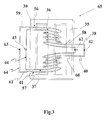
- This invention relates to a SIP (Symmetrical-in-Parallel) Induction Coil is made of winding two conductive wires symmetrically around a magnetic core and connecting them in parallel (refer to four figures in four pages).
- SIP Induction Coils can be applied to construct electromagnetic devices which have unique outstanding features of reduced magnetization current, reduced cupper loss, higher power efficiency, lower temperature-rise and reduced size (volume) of the electromagnetic devices.
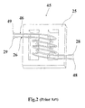
- Any prior-art induction coil is made of winding a single conductive wire around the magnetic core from one end to the other end and winding back, and repeating winding cycles until the required number of turns are completed.
- two prior-art induction coils single-wire coils
- it can induce voltage difference to cause internal circulating current within two coils which incurs additional cupper loss.
- any prior-art induction coils single wire wound coils
- it would induce additional cupper loss, higher temperature-rise and lower efficiency
- the invention of a SIP (Symmetrical-In-Parallel) Induction Coil is made of winding two conductive wires symmetrically around a magnetic core from the center of the core toward the two ends and winding back to the center, and repeating winding cycles until the required number of turns are completed and the wound coils are connected in parallel to form a SIP Induction Coil.
- the invention of a SIP Induction Coil is not limited to an induction coil constructed from the above of two identical coils wound symmetrically and connected in parallel but also includes any combination of a pair of SIP Induction Coils or more pairs of SIP Induction Coils.
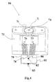
- the invention of SIP Induction Coils can be applied to various electromagnetic devices.
- SIP Electromagnetic Devices include inductors, transformers, motors and generators with many great benefits of reduced cupper loss, lower temperature-rise, better performance, higher efficiency, and reduced size (volume) of the devices based on the same output power as the prior-art devices.
- the invention of the SIP Induction Coils is also aimed to achieve another unique feature of "balance" concept in designing SIP Electromagnetic Devices.
- the invention of SIP Induction Coils and SIP Electromagnetic Devices can provide many great benefits of reduced magnetization current, less cupper loss, lower temperature-rise, better performance, higher efficiency and reduced size (volume) of electromagnetic devices (inductors, transformers, motors and generators) for more energy savings and reduced harmfulness to animals and plants from less intensity of electromagnetic fields.
- the invention can provide designers more freedom (fewer constraints) of selecting electromagnetic parameters in designing electromagnetic devices.
- Table 1a Power Tests of a Standard Transformer (Prior Art) and a SIP Transformer Type of Transformer Load (Ohm) Voltage In (V) Current In (A) Voltage Out (V) Current Out (A) Standard Transformer 8.0 60.0 0.018 1.80 0.185 SIP Transformer 8.0 60.0 0.012 1.93 0.196 Standard Transformer 8.0 120.0 0.182 3.57 0.360 SIP Transformer 8.0 120.0 0.069 3.88 0.392 Standard Transformer 4.0 120.0 0.1765 3.50 0.865 SIP Transformer 4.0 120.0 0.0710 3.75 0.925 Standard Transformer 1.5 120.0 0.1630 3.30 1.968 SIP Transformer 1.5 120.0 0.0905 3.44 2.050
- Table 1b Resistance Measurements of a Standard Transformer (Prior Art) and a SIP Transformer Type of Transformer Primary Coil Resistance (Ohm) Secondary Coil Resistance(Ohm) Standard Transformer 129.0 0.2 SIP Trnsformer 127.6 0.3
- Table 1c Temperature Measurements of a Standard Transformer (Prior Art) and a SIP Transformer
Landscapes
- Engineering & Computer Science (AREA)
- Power Engineering (AREA)
- Manufacturing & Machinery (AREA)
- Coils Of Transformers For General Uses (AREA)
- Coils Or Transformers For Communication (AREA)
Applications Claiming Priority (1)
| Application Number | Priority Date | Filing Date | Title |
|---|---|---|---|
| TW098134775A TW201113915A (en) | 2009-10-14 | 2009-10-14 | Symmetrical parallel induction coils for electromagnetic devices |
Publications (2)
| Publication Number | Publication Date |
|---|---|
| EP2312596A2 true EP2312596A2 (de) | 2011-04-20 |
| EP2312596A3 EP2312596A3 (de) | 2012-05-02 |
Family
ID=43480925
Family Applications (1)
| Application Number | Title | Priority Date | Filing Date |
|---|---|---|---|
| EP10187354A Withdrawn EP2312596A3 (de) | 2009-10-14 | 2010-10-13 | SIP-Induktionsspulen für elektromagnetische Vorrichtungen |
Country Status (4)
| Country | Link |
|---|---|
| US (1) | US20110084792A1 (de) |
| EP (1) | EP2312596A3 (de) |
| JP (1) | JP3164981U (de) |
| TW (1) | TW201113915A (de) |
Families Citing this family (6)
| Publication number | Priority date | Publication date | Assignee | Title |
|---|---|---|---|---|
| JP6287678B2 (ja) * | 2014-08-08 | 2018-03-07 | 株式会社豊田自動織機 | コイル部品 |
| CN104300834A (zh) * | 2014-09-25 | 2015-01-21 | 陈新培 | 一种新型磁能发电机 |
| CN107642900A (zh) * | 2017-10-10 | 2018-01-30 | 沈阳日月蓝天新能源科技有限公司 | 一种电磁线圈加热循环水设备 |
| JP7057505B2 (ja) * | 2018-08-29 | 2022-04-20 | 日本電信電話株式会社 | 修復装置 |
| CN112052569B (zh) * | 2020-08-18 | 2024-04-05 | 保定天威集团特变电气有限公司 | 一种变压器线圈环流损耗计算方法及装置 |
| CN112162225B (zh) * | 2020-11-03 | 2024-01-05 | 苏州斯玛维科技有限公司 | 一种单边磁体结构 |
Family Cites Families (23)
| Publication number | Priority date | Publication date | Assignee | Title |
|---|---|---|---|---|
| US2082121A (en) * | 1929-12-27 | 1937-06-01 | Albert B Rypinski | Slow magnetic regulating device |
| US1972319A (en) * | 1933-05-18 | 1934-09-04 | Albert B Rypinski | Coil for slow electromagnets and reactors |
| US2354332A (en) * | 1942-05-22 | 1944-07-25 | Wladimir J Polydoroff | Loop antenna |
| US2401882A (en) * | 1942-05-22 | 1946-06-11 | Rca Corp | Ultra high frequency inductor |
| US2495157A (en) * | 1948-08-17 | 1950-01-17 | Westinghouse Electric Corp | Electromagnetic device |
| US2741121A (en) * | 1952-06-17 | 1956-04-10 | Vitro Corp Of America | Means for minimizing electrostatic voltages in a flowmeter |
| US3392326A (en) * | 1966-09-28 | 1968-07-09 | Gen Electric | Coil winding buffer conductors having impedance means |
| US3624577A (en) * | 1969-10-17 | 1971-11-30 | Westinghouse Electric Corp | Tapped multilayer winding for electrical inductive apparatus |
| BE789869A (fr) * | 1971-10-09 | 1973-04-09 | Philips Nv | Dispositif de reproduction d'images de television en couleur, muni d'untube cathodique |
| CA965166A (en) * | 1972-12-28 | 1975-03-25 | Trench Electric Limited | Air core duplex reactor |
| US4473811A (en) * | 1982-02-25 | 1984-09-25 | General Instrument Corporation | Single bobbin transformer having multiple delink windings and method of making same |
| JPS60250609A (ja) * | 1984-05-28 | 1985-12-11 | S M K Kk | インピーダンス変換トランス |
| US4806834A (en) * | 1987-04-16 | 1989-02-21 | Donald Goodman | Electrical circuit for inductance conductors, transformers and motors |
| US5200718A (en) * | 1990-10-23 | 1993-04-06 | Smk Co., Ltd. | Balun transformer with common mode coil |
| DE69417950T2 (de) * | 1993-05-26 | 1999-09-23 | Nippon Telegraph And Telephone Corp., Tokio/Tokyo | Filter zur Erzielung der elektromagnetischen Kompatibilität für eine symmetrische mehradrige Fernmeldeleitung |
| DE19934767A1 (de) * | 1999-07-23 | 2001-01-25 | Philips Corp Intellectual Pty | Magnetisches Bauelement |
| WO2003032477A2 (en) * | 2001-10-12 | 2003-04-17 | Northeastern University | Integrated magnetics for a dc-dc converter with flexible output inductor |
| US7123122B2 (en) * | 2003-04-18 | 2006-10-17 | Medtronic, Inc. | Center tapped chip inductor |
| CN100426637C (zh) * | 2003-08-16 | 2008-10-15 | 鸿富锦精密工业(深圳)有限公司 | 直流无刷马达 |
| US7161458B2 (en) * | 2005-02-22 | 2007-01-09 | Delta Electronics, Inc. | Electromagnetic device having independent inductive components |
| DE102006062205B4 (de) * | 2006-08-25 | 2012-07-19 | Minebea Co., Ltd. | Hochspannungstransformator |
| JP4674590B2 (ja) * | 2007-02-15 | 2011-04-20 | ソニー株式会社 | バラントランス及びバラントランスの実装構造、並びに、この実装構造を内蔵した電子機器 |
| US7982572B2 (en) * | 2008-07-17 | 2011-07-19 | Pulse Engineering, Inc. | Substrate inductive devices and methods |
-
2009
- 2009-10-14 TW TW098134775A patent/TW201113915A/zh unknown
-
2010
- 2010-10-12 US US12/903,179 patent/US20110084792A1/en not_active Abandoned
- 2010-10-13 EP EP10187354A patent/EP2312596A3/de not_active Withdrawn
- 2010-10-13 JP JP2010006793U patent/JP3164981U/ja not_active Expired - Fee Related
Non-Patent Citations (1)
| Title |
|---|
| None |
Also Published As
| Publication number | Publication date |
|---|---|
| US20110084792A1 (en) | 2011-04-14 |
| TW201113915A (en) | 2011-04-16 |
| JP3164981U (ja) | 2010-12-24 |
| EP2312596A3 (de) | 2012-05-02 |
Similar Documents
| Publication | Publication Date | Title |
|---|---|---|
| JP4800451B1 (ja) | 高周波トランス | |
| EP2312596A2 (de) | SIP-Induktionsspulen für elektromagnetische Vorrichtungen | |
| JP5813320B2 (ja) | 高電圧用途のための高周波変圧器 | |
| US9455084B2 (en) | Variable core electromagnetic device | |
| CN110690033A (zh) | 线性电磁装置 | |
| CN114424304B (zh) | 作为用于中频变压器的集成结构的部分的绕组配置 | |
| WO2012136754A1 (en) | Cable and electromagnetic device comprising the same | |
| CN116095895A (zh) | 电池电芯加热装置和锂电设备 | |
| WO2022018439A1 (en) | Inductive coil assembly | |
| Li et al. | A transformer design with pcb litz wire concept for solid state transformer | |
| JP2011187600A (ja) | 電磁コイル及び変圧器 | |
| JP2025529083A (ja) | 電気機械 | |
| US11909284B2 (en) | Flat-type stator with multilayer coils for disc-type motor | |
| CN211858327U (zh) | 电感结构、电抗装置和变压装置 | |
| US7528692B2 (en) | Voltage stress reduction in magnetics using high resistivity materials | |
| JP6236853B2 (ja) | 中空筒型リアクトル装置、中空筒型コンバータ装置、および中空筒型電源装置 | |
| CN101055799B (zh) | 一种变压器绕组的制作方法及变压器 | |
| CN111524686B (zh) | 电感结构、电抗装置和变压装置 | |
| CN202394669U (zh) | 线饼及使用该线饼的变压器 | |
| Wang et al. | Design of multi-permeability distributed air-gap inductors | |
| Mohamadi et al. | Airgap-less integrated magnetic array using high performance magnetic material in the EV chargers | |
| TWM395896U (en) | Symmetrical parallel induction coils for electromagnetic devices | |
| CN102063999A (zh) | 对称并联感应线圈应用于电磁器机 | |
| CN112530682A (zh) | 具有带有非耦合磁场的多个绕组的电感器结构 | |
| RU120519U1 (ru) | Вторичный источник питания с отбором мощности от фазного провода линии электропередачи высокого напряжения промышленной частоты |
Legal Events
| Date | Code | Title | Description |
|---|---|---|---|
| PUAI | Public reference made under article 153(3) epc to a published international application that has entered the european phase |
Free format text: ORIGINAL CODE: 0009012 |
|
| 17P | Request for examination filed |
Effective date: 20101018 |
|
| AK | Designated contracting states |
Kind code of ref document: A2 Designated state(s): AL AT BE BG CH CY CZ DE DK EE ES FI FR GB GR HR HU IE IS IT LI LT LU LV MC MK MT NL NO PL PT RO RS SE SI SK SM TR |
|
| AX | Request for extension of the european patent |
Extension state: BA ME |
|
| PUAL | Search report despatched |
Free format text: ORIGINAL CODE: 0009013 |
|
| AK | Designated contracting states |
Kind code of ref document: A3 Designated state(s): AL AT BE BG CH CY CZ DE DK EE ES FI FR GB GR HR HU IE IS IT LI LT LU LV MC MK MT NL NO PL PT RO RS SE SI SK SM TR |
|
| AX | Request for extension of the european patent |
Extension state: BA ME |
|
| RIC1 | Information provided on ipc code assigned before grant |
Ipc: H03H 7/42 20060101ALI20120327BHEP Ipc: H01F 29/02 20060101ALI20120327BHEP Ipc: H01F 27/29 20060101ALI20120327BHEP Ipc: H01F 21/12 20060101ALI20120327BHEP Ipc: H01F 7/06 20060101ALI20120327BHEP Ipc: H01F 5/00 20060101ALI20120327BHEP Ipc: H02K 21/18 20060101ALI20120327BHEP Ipc: H02K 3/28 20060101ALI20120327BHEP Ipc: H01F 41/06 20060101ALI20120327BHEP Ipc: H01F 27/34 20060101ALI20120327BHEP Ipc: H01F 17/04 20060101AFI20120327BHEP |
|
| 17Q | First examination report despatched |
Effective date: 20130925 |
|
| STAA | Information on the status of an ep patent application or granted ep patent |
Free format text: STATUS: THE APPLICATION IS DEEMED TO BE WITHDRAWN |
|
| 18D | Application deemed to be withdrawn |
Effective date: 20131206 |