EP2312194A1 - Attachment device - Google Patents
Attachment device Download PDFInfo
- Publication number
- EP2312194A1 EP2312194A1 EP10192297A EP10192297A EP2312194A1 EP 2312194 A1 EP2312194 A1 EP 2312194A1 EP 10192297 A EP10192297 A EP 10192297A EP 10192297 A EP10192297 A EP 10192297A EP 2312194 A1 EP2312194 A1 EP 2312194A1
- Authority
- EP
- European Patent Office
- Prior art keywords
- housing
- fastening device
- drill
- housing chamber
- substrate
- Prior art date
- Legal status (The legal status is an assumption and is not a legal conclusion. Google has not performed a legal analysis and makes no representation as to the accuracy of the status listed.)
- Granted
Links
- 238000007789 sealing Methods 0.000 claims abstract description 28
- 238000004140 cleaning Methods 0.000 claims description 78
- 239000000758 substrate Substances 0.000 claims description 54
- 238000009423 ventilation Methods 0.000 claims description 33
- 238000005553 drilling Methods 0.000 claims description 30
- 238000004891 communication Methods 0.000 claims description 7
- 230000001154 acute effect Effects 0.000 claims description 5
- 239000012530 fluid Substances 0.000 claims description 3
- 239000002689 soil Substances 0.000 claims 1
- 239000000463 material Substances 0.000 description 10
- 238000013022 venting Methods 0.000 description 10
- 239000002184 metal Substances 0.000 description 7
- 238000012546 transfer Methods 0.000 description 5
- 239000000853 adhesive Substances 0.000 description 4
- 230000001070 adhesive effect Effects 0.000 description 4
- 230000001681 protective effect Effects 0.000 description 3
- 241000238633 Odonata Species 0.000 description 2
- 230000002349 favourable effect Effects 0.000 description 2
- 238000003780 insertion Methods 0.000 description 2
- 230000037431 insertion Effects 0.000 description 2
- 238000010330 laser marking Methods 0.000 description 2
- 239000012528 membrane Substances 0.000 description 2
- 238000007790 scraping Methods 0.000 description 2
- CWYNVVGOOAEACU-UHFFFAOYSA-N Fe2+ Chemical compound [Fe+2] CWYNVVGOOAEACU-UHFFFAOYSA-N 0.000 description 1
- 230000000295 complement effect Effects 0.000 description 1
- 238000000151 deposition Methods 0.000 description 1
- 238000013461 design Methods 0.000 description 1
- 239000000428 dust Substances 0.000 description 1
- 230000000694 effects Effects 0.000 description 1
- 230000007613 environmental effect Effects 0.000 description 1
- 238000000605 extraction Methods 0.000 description 1
- 238000004519 manufacturing process Methods 0.000 description 1
- 239000002245 particle Substances 0.000 description 1
- 238000003825 pressing Methods 0.000 description 1
- 230000000717 retained effect Effects 0.000 description 1
- 238000010408 sweeping Methods 0.000 description 1
- 230000032258 transport Effects 0.000 description 1
- 208000008918 voyeurism Diseases 0.000 description 1
Images


Classifications
-
- B—PERFORMING OPERATIONS; TRANSPORTING
- B25—HAND TOOLS; PORTABLE POWER-DRIVEN TOOLS; MANIPULATORS
- B25B—TOOLS OR BENCH DEVICES NOT OTHERWISE PROVIDED FOR, FOR FASTENING, CONNECTING, DISENGAGING OR HOLDING
- B25B11/00—Work holders not covered by any preceding group in the subclass, e.g. magnetic work holders, vacuum work holders
- B25B11/005—Vacuum work holders
- B25B11/007—Vacuum work holders portable, e.g. handheld
-
- F—MECHANICAL ENGINEERING; LIGHTING; HEATING; WEAPONS; BLASTING
- F16—ENGINEERING ELEMENTS AND UNITS; GENERAL MEASURES FOR PRODUCING AND MAINTAINING EFFECTIVE FUNCTIONING OF MACHINES OR INSTALLATIONS; THERMAL INSULATION IN GENERAL
- F16M—FRAMES, CASINGS OR BEDS OF ENGINES, MACHINES OR APPARATUS, NOT SPECIFIC TO ENGINES, MACHINES OR APPARATUS PROVIDED FOR ELSEWHERE; STANDS; SUPPORTS
- F16M13/00—Other supports for positioning apparatus or articles; Means for steadying hand-held apparatus or articles
- F16M13/02—Other supports for positioning apparatus or articles; Means for steadying hand-held apparatus or articles for supporting on, or attaching to, an object, e.g. tree, gate, window-frame, cycle
- F16M13/022—Other supports for positioning apparatus or articles; Means for steadying hand-held apparatus or articles for supporting on, or attaching to, an object, e.g. tree, gate, window-frame, cycle repositionable
-
- G—PHYSICS
- G01—MEASURING; TESTING
- G01D—MEASURING NOT SPECIALLY ADAPTED FOR A SPECIFIC VARIABLE; ARRANGEMENTS FOR MEASURING TWO OR MORE VARIABLES NOT COVERED IN A SINGLE OTHER SUBCLASS; TARIFF METERING APPARATUS; MEASURING OR TESTING NOT OTHERWISE PROVIDED FOR
- G01D11/00—Component parts of measuring arrangements not specially adapted for a specific variable
- G01D11/30—Supports specially adapted for an instrument; Supports specially adapted for a set of instruments
Definitions
- the invention relates to a fastening device for releasably securing an object to a substrate, in particular a wall or a ceiling, with a suction plate on which a sealing ring is held for engagement with the ground, and with an electric vacuum pump, with a sealable from the sealing ring gap between the suction plate and the substrate with negative pressure can be acted upon.
- an object for example a measuring device, a marking device or a dirt collecting device, temporarily be attached to a substrate, in particular on a wall or a ceiling.
- the suction plate can be applied with the interposition of the sealing ring to the substrate, and then can be sucked by means of the vacuum pump, the space between the suction plate and the substrate and thus subjected to negative pressure. This has the consequence that the suction plate pneumatically adheres to the substrate.
- a fastening device in which the suction plate on its side facing away from the sealing ring rear side projects from the electric vacuum pump and in the suction plate, a recess is formed, which receives a ferrous support plate.
- a measuring device on the support plate by means of a magnet.
- the suction plate also houses a pressure gauge, with the aid of which the negative pressure between the suction plate and the substrate can be measured. With the help of support pins, by the suction plate protrude in the direction of the ground, a defined distance between the suction plate and the substrate can be maintained.
- the known fastening device is unwieldy and heavy and requires the provision of a mains voltage to which the electric vacuum pump can be connected by means of a connecting cable.
- Object of the present invention is to provide a fastening device of the type mentioned in such a way that it can be operated independently of a mains voltage and is easier to handle.
- suction plate is integrated into a housing which receives the vacuum pump, a battery and an electrical switching element for switching on and off the vacuum pump.
- the fastening device according to the invention forms a self-sufficient device, with which an object can be temporarily attached to a substrate, in particular a wall or a ceiling, without having to provide a mains voltage and a connecting cable.
- a substrate in particular a wall or a ceiling
- the fastening device according to the invention is characterized by a simple handling, because all components of the fastening device are integrated into the housing, which may be configured, for example, cuboid or cylindrical and can be taken by the user in a simple manner.
- the vacuum pump By means of the vacuum pump, the intermediate space between the suction plate of the housing and the substrate can be sucked off when the housing is applied to the substrate so that the housing adheres pneumatically to the substrate.
- the adhesion takes place as long as the vacuum pump is in operation. If it is switched off by means of the electrical switching device, it can be due to leaks ventilation of the gap, so that the housing can be solved in a simple way by the user again from the ground.
- the fastening device according to the invention is inexpensive to produce.
- the vacuum pump is designed in the form of a diaphragm pump.
- the fastening device comprises a connecting element for releasably connecting an object to the housing.
- a connecting element for releasably connecting an object to the housing.
- the connecting element comprises a receptacle for the positive connection of the housing with the object.
- the receptacle can be designed, for example, as a T-shaped or dovetail-shaped groove into which a correspondingly formed strip of the object can be inserted.
- This allows a detachable connection of the housing with the object and has the advantage that different Objects can be connected to the housing of the fastening device.
- the housing can be connected to a position-determining device, a measuring device, for example a roll-up measuring tape, and / or to a marking device, for example a laser marking device.
- a marking device for example a laser marking device.
- the housing is also connectable to a Bohrschmutzauffang worn, which can be penetrated by a drill for introducing a hole in the ground and serves to receive the drilling dirt accumulating during drilling.
- a dragonfly can be used for horizontal and / or vertical alignment of the fastening device to a wall or a ceiling.
- a bonding pad can also be used as the connecting element, which is held on the housing and is preferably covered by a peelable protective film.
- a temporary object to be fastened to the substrate can be adhesively bonded to the housing of the fastening device.
- the seal held on the suction plate is preferably made of an elastically deformable material. It is favorable if it is adaptable to slightly curved surfaces of the substrate and gap-filling, so that the region surrounded by the sealing ring of the suction plate can be sealed airtight, if the suction plate is applied to the substrate with the interposition of the sealing ring.
- the fastening device can be pneumatically fixed to a substrate by the suction space sealed by the sealing ring between the suction plate and the substrate is sucked by means of the vacuum pump.
- the fastening device has a ventilation element for venting the gap.
- the smooth surface may cause the gap to be vented slowly due to leakage when the vacuum pump is turned off.
- the ventilation element With the help of the ventilation element, however, the gap can be ventilated within a very short time, so that the negative pressure in the intermediate space is eliminated and thus the fastening device can be easily removed from the ground.
- the ventilation element can be electrically actuated.
- the ventilation element is coupled to the vacuum pump such that the ventilation element ventilates the intermediate space when the vacuum pump is switched off.
- the ventilation element is manually operable. It can thus be operated by the user to ventilate the gap.
- the ventilation element comprises a resiliently biased in a closed position ventilation valve.
- a flow connection between the gap and the environment of the fastening device can be controlled.
- the vent valve In the unactuated state, the vent valve assumes a closed position due to its spring load, so that the flow connection between the gap and the environment is interrupted.
- For ventilation of the gap of the switching state of the ventilation valve is changed so that it passes into its open position and thereby the gap can be ventilated.
- the ventilation valve cooperates with a manually operable switch plunger.
- the switching position of the ventilation valve can be changed, in particular, the ventilation valve can be transferred against the action of a spring force in its open position.
- the switch plunger passes through a wall of the housing facing away from the background and protrudes outward beyond the rear wall.
- the venting element may, like the vacuum pump, the battery and the electrical switching element, be arranged inside the housing.
- the housing of the fastening device forms a flow channel which is in flow communication with the vacuum pump and passes through the suction plate in the area surrounded by the sealing ring.
- the flow channel forms at least a part of a Suction line, via which the suctioned gap is in flow communication with the vacuum pump.
- the flow channel is connected to the vacuum pump via a flexible suction hose arranged inside the housing.
- the flexible connection of the vacuum pump via the suction hose with the rigid flow channel facilitates the insertion of the vacuum pump during assembly of the fastening device.
- a filter element is arranged in the flow channel, preferably the filter element can be inserted into the flow channel.
- the filter element By means of the filter element can be avoided that the vacuum pump comes into contact with dirt particles. This can extend the life of the vacuum pump.
- the filter element completely fills the flow channel.
- the filter element preferably has a paper filter which can be inserted into the flow channel.
- the flow channel extends in an intermediate wall of the housing.
- the mechanical strength of the housing can be increased and at the same time can be provided with their help a flow channel. This makes it possible to manufacture and mount the fastening device particularly cost-effectively.
- the intermediate wall is divided in an advantageous embodiment, the housing in two housing chambers, wherein a first housing chamber the Vacuum pump, the battery and the switching device receives. All electrical components of the fastening device are thus arranged in the first housing chamber and thereby protected from environmental influences. When using a ventilation element this can also be arranged in the first housing chamber.
- the first housing chamber is accessible to the user for replacement of the battery, which in a particularly preferred embodiment is designed to be rechargeable.
- a second housing chamber receives an object to be fastened.
- the second housing chamber forms a receptacle into which the object to be temporarily fixed can be inserted.
- a Bohrschmutzauffanging device can be temporarily attached to a substrate, in particular a wall or a ceiling.
- Bohrschmutzauffangvoriques can be collected during the introduction of a hole in the ground accumulating Bohrschmutz, ie drilling material and Bohrstaub.
- a Bohrschmutzauffang in the second housing chamber a Bohrschmutzauffang shark is integrated and the second housing chamber is enforced by a drill for introducing a hole in the ground, said second housing chamber defines a Bohrschmutzsammelraum and at least receives a cleaning device for cleaning the drill.
- the housing can be applied to the ground and be set pneumatically by turning on the vacuum pump on this, as already explained above. It can then be passed through a rotatably held on a drill drill through the second housing chamber for introducing a hole in the ground. Accumulating Bohrschmutz is transferred from the drill in the manner of a screw conveyor in the interior of the second housing chamber and accumulates in the Bohrschmutzsammelraum. To clean the drill during the introduction of the bore and / or when pulling out the drill from the second housing chamber this takes on at least one cleaning device. This ensures that the drilling debris remains within the Bohrschmutzsammelraumes and does not get into the outer area of the housing.
- a first cleaning device comprises at least one first cleaning brush scraping off the drill when pulling it out of the second housing chamber.
- the drill can be stripped after the introduction of a hole in the ground, while it is pulled out of the second housing chamber.
- flexible cleaning elements may be used, for example rubber strips which strip the drill from the second housing chamber during extraction and thus free it from adhering drilling debris.
- a first cleaning brush is designed annular and enforceable by the drill. This ensures a structurally simple way that the drilling debris adhering to the drill along its circumference can be removed.
- a first cleaning brush is designed as a double brush and has two facing bristle rows, which receive the drill between them.
- the bristle rows are inexpensive to produce, and by using two facing bristle rows of the drill can be virtually completely cleaned in the circumferential direction.
- the second housing chamber has two mutually aligned, by the drill enforceable housing openings, wherein an end-side housing opening facing the ground and a rear housing opening facing away from the ground and wherein the first cleaning means covers the rear housing opening at least partially.
- the first cleaning device faces the front-side housing opening and has a cover. As a result, the risk is kept particularly low that when introducing a hole in a ceiling drilling debris falls through the housing.
- the cover on the outer periphery of the drill can be applied.
- the cover is made of a flexible material, for example a rubber-like material.
- the cover may be in the form of a membrane.
- the cover covers in a preferred embodiment of the invention, the rear housing opening.
- a second cleaning device comprises at least one second cleaning brush scraping off the rotating drill during drilling.
- the rotary drill forms a screw conveyor, which transports the resulting drilling debris out of the borehole and transfers it to the interior of the second housing chamber. In the second housing chamber of the rotating drill is stripped from the at least one second cleaning brush and thus freed from Bohrschmutz.
- first cleaning brush which wipes the drill when pulling out of the second housing chamber
- second cleaning brush which strips the rotating drill when introducing a hole in the ground
- the second cleaning brush is arranged between the first cleaning brush and the frontal housing opening.
- the rotary drill is first brushed off during drilling by the second cleaning brush, in particular, the at least one helical bore of the drill is freed from Bohrschmutz. Drilling debris not covered by the second cleaning brush will be transferred from the rotating drill to the first cleaning brush in the drill hole and brushed off.
- the cleaning effect of the first cleaning brush thus unfolds not only when pulling out the drill from the second housing chamber but also during drilling. This achieves optimal cleaning of the drill.
- the second cleaning brush is configured annular and can be enforced by the drill.
- the rotary drill is brushed off in such a configuration in the circumferential direction from all sides simultaneously.
- this makes it possible in a structurally simple manner to reliably clean off at least one drilling groove in which the drilling debris is led out of the borehole.
- a second cleaning brush on at least one row of bristles which is aligned parallel or at an acute angle to the drill longitudinal axis.
- the drilling dirt led out of the borehole in the boring groove of the drill is fed laterally to the second cleaning brush within the second housing chamber in such a configuration and can be brushed off reliably therefrom.
- a second cleaning brush is designed as a double brush and has two facing bristle rows, which receive the drill between them. It is particularly advantageous if the two rows of bristles are aligned parallel or at an acute angle to the drill longitudinal axis. However, such an alignment is not absolutely necessary, it can also be provided that the two rows of bristles have an orientation perpendicular to the drill longitudinal axis.
- Bohrschmutz In order to avoid that can accumulate during drilling between the substrate and the outer wall of the second housing chamber Bohrschmutz, is provided in a particularly advantageous embodiment that the frontal housing opening is penetrated by a dirt guide sleeve.
- Bohrschmutz By means of the dirt guide sleeve Bohrschmutz is reliably transferred in the Bohrschmutzsammelraum the second housing chamber in the region of the frontal housing opening.
- the dirt guide sleeve protrudes on the outside over the second housing chamber. This has the advantage that the dirt guide sleeve can be applied directly to the ground.
- the dirt guide sleeve is surrounded in its outwardly projecting region by a sealing ring.
- the latter is preferably made of an elastically deformable material.
- it can be designed such that it is adaptable to slightly curved surfaces of the substrate and gap-filling, so that the area between the borehole and the frontal housing opening of the second housing chamber is reliably sealed dust-tight even on a rough surface.
- the dirt guide sleeve protrudes into the second housing chamber. It thereby forms from the frontal housing opening inwardly projecting collar, which retains accumulated within the second housing chamber Bohrschmutz in the second housing chamber.
- the dirt guide sleeve widens conically into the interior of the second housing chamber. This ensures that the drilling debris depositing on the dirt guide sleeve automatically slides along the dirt guide sleeve and is thus transferred into the interior of the second housing chamber.
- the dirt guide sleeve is made in an advantageous embodiment of metal, in particular of hardened metal.
- the rear housing opening is penetrated by a guide bush.
- the guide bush By means of the guide bush, the insertion of the drill into the second housing chamber and also its orientation during drilling is simplified.
- the guide bush is conveniently made of metal, in particular of hardened metal.
- the clear diameter of the guide bush corresponds to the clear diameter of the dirt guide sleeve. This simplifies the alignment of the drill when inserting a hole in the ground.
- the guide bush protrudes outward from the second housing chamber. It can form a collar in this outstanding area, with which it can be applied to the outside of the second housing chamber.
- the guide bush projects inwardly into the second housing chamber. It can form a protruding from the rear housing opening collar inside the housing chamber, which reduces the risk that when removing the second housing chamber from the ground Bohrschmutz can escape from the second housing chamber via the rear housing opening.
- a turbine can also be used.
- the turbine may be disposed in the first or second housing chamber and, while drilling a bore, may aspirate or deflate the drill within the housing.
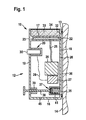
- FIG. 1 schematically a first embodiment of a fastening device according to the invention is shown, which is generally occupied by the reference numeral 10. It comprises a housing 12 which can be applied with the interposition of a sealing ring 13 against a substrate 14, for example a building wall or a building ceiling.
- the housing 12 has a bottom wall 16 and a ceiling wall 17 which are integrally connected to one another via an end wall 18 and a rear wall 19.
- the end wall 18 forms a suction plate, on the outer side 20 of the sealing ring 13 is held interchangeable.
- a flow channel 22 is formed, which passes through the end wall 18 and is completely filled by a filter element 23.
- the flow channel 22 is in fluid communication with an electric diaphragm pump 26 which is disposed within the housing 12 and which is connected to an electric battery 27 and via a connecting cable 28 with an electromechanical switching element 29 arranged in the housing 12 in electrical connection stands, which has a rear wall 19 by cross-actuating member 30.
- a ventilation opening 35 is formed, on the inside a ventilation element in the form of a ventilation valve 37 is held, which by means of a switch plunger 38 which passes through the rear wall 19 and is guided within the housing 12 in a guide sleeve 39, can be actuated.
- the venting valve 37 comprises a closing spring 41, which biases the venting valve 37 automatically into its closed position. By pressing the switch plunger 38, the user can transfer the ventilation valve 37 against the action of the closing spring 41 into an open position in which it releases a flow connection between the ventilation opening 35 and a through opening 45 formed in the bottom wall 16.
- the housing 12 forms a trough-shaped receptacle 32, in which an adhesive pad 33 is inserted, which is covered by a peelable protective film 34.
- the housing 12 can be applied to the substrate 14, and by operating the switching element 29, the diaphragm pump 26 can be set in motion, so that a space sealed by the sealing ring 13 airtight space 36 between the end wall 18 and the substrate 14 is sucked off and thus subjected to negative pressure. Due to the forming negative pressure, the fastening device 10 adheres to the substrate 14, without this being damaged. A temporarily to be fixed object can now be connected by peeling off the protective film 34 with the adhesive pad 33, so that it is reliably held on the adhesive pad 33 on the housing 12.
- the diaphragm pump 26 is switched off for this purpose and the switching tappet 38 is actuated for a short time, so that the intermediate space 36 is ventilated via the ventilation opening 35, the interior of the housing 12 and the passage opening 45.
- the fastening device 10 can then be removed by the user again from the substrate 14.
- FIG. 2 a second embodiment of a fastening device according to the invention is shown and taken overall by the reference numeral 40. It is largely identical to the above-described fastening device 10 and comprises a housing 42 which can be applied with the interposition of a replaceable sealing ring 43 to a substrate 44.
- the housing 42 has a bottom wall 46 and a top wall 47 which integrally via an end wall 48 and a rear wall 49 connected to each other.
- the end wall 48 forms a suction plate, on whose underside 14 facing outer side 50 of the sealing ring 43 is held.
- the housing 42 also has an intermediate wall 52 which is double-walled and divides the housing 42 into a first housing chamber 53 and a second housing chamber 54.
- the intermediate wall 52 has a first, the first housing chamber 53 facing wall layer 56 and a second, the second housing chamber facing wall layer 57, which are arranged parallel and spaced from each other and between them define a flow channel 59, which passes through the end wall 48 and in the Interspace 60 between the end wall 48 and the base 44 opens.
- the first housing chamber 53 accommodates a diaphragm pump 62, a battery 63 and an electrical switching element 64, which engages through the rear wall 49 with an actuating element 65. Via a connecting cable 66, the switching member 64 is in electrical communication with the diaphragm pump 62, and by means of a flexible suction hose 68, a flow connection between the diaphragm pump 62 and the flow channel 59 is established within the first housing chamber 53.
- the flow channel 59 is completely filled by a filter element 61 ,
- vent valve 55 which controls a flow connection between a ventilation opening 58 of the end wall 48 and a through opening 67 formed in the bottom wall 46.
- vent valve 37 may also be the vent valve 55 by means a switching plunger 69 are converted from its closed position against the action of a closing spring in an open position for venting the gap 60th
- a dovetail groove 70 is formed, which forms a receptacle for the positive connection of a temporarily to be fixed to the substrate 44 to the housing 42nd
- an object is to be fastened temporarily to the substrate 44 by means of the fastening device 40, then it can be detachably connected to the housing 42 by means of a strip configured to be complementary to the groove 70 by inserting it into the groove 70.
- the housing 42 can then be placed with the end wall 48 to the substrate 44, and by turning on the diaphragm pump 62, the gap 60 can be sucked off, so that the housing 42 pneumatically adheres to the substrate 44, as long as the diaphragm pump 62 is in operation. If the diaphragm pump 62 is switched off by the user and the switch plunger 69 is actuated, the negative pressure in the intermediate space 60 is reduced due to the ventilation via the ventilation valve 55 and the housing 42 can be removed again from the base 44.
- FIGS. 3 to 7 shows a third embodiment of a generally occupied by the reference numeral 75 fastening device is shown.
- This has a housing 77 which can be applied with the interposition of a replaceable sealing ring 78 to a substrate 80, in particular to a building wall or a building ceiling.
- the housing 77 has a bottom wall 82 and a top wall 83, which are integrally connected to one another via an end wall 84 and a rear wall 85.
- the housing 77 comprises an intermediate wall 87, which connects the end wall 84 in one piece with the rear wall 85 and is designed double-walled with a first wall layer 88 and a second wall layer 89.
- the housing 77 is divided into a first housing chamber 91 and a second housing chamber 92, and between the first wall layer 88 and the second wall layer 89 extends a flow channel 93 which receives a filter element 94 and in the region surrounded by the sealing ring 78 End wall 84 passes through.
- the first housing chamber 91 accommodates a diaphragm pump 96, a battery 97 and an electromechanical switching element 98 with an actuating element 99, the switching element 98 being electrically connected to the diaphragm pump 96 via a connecting cable 100 and the diaphragm pump 96 being connected to the flow channel via a flexible suction hose 101 93 is in fluid communication.
- the first housing chamber 91 receives a vent valve 86 which is disposed on the inside of a vent opening 90 of the end wall 84 and can be actuated by the user via a switch plunger 95.
- venting valve 86 Due to the use of a closing spring, the venting valve 86 automatically assumes its closed position, in which it interrupts a flow connection between the venting opening 90 and a passage opening 81 formed in the bottom wall 82. By operating the switch plunger 95, the user can transfer the vent valve 86 in its open position.
- the end wall 84 forms a suction plate 102, on the outside of the sealing ring 78 is held and together with the base 80 defines a gap 103 which can be sucked by the diaphragm pump 96 via the suction hose 101 and the flow channel 93, so that the housing 77 pneumatically adheres to the substrate 80.
- the user can actuate the switch plunger 95 for this purpose, so that the ventilation valve 86 moves into its open position and thus the intermediate space 103 can be ventilated via the ventilation opening 90.
- attachment means 10 and 40 are releasably connectable to a temporarily on the respective substrate 14 and 44 to be fastened object is in the housing 77 of in FIG. 3
- Fastening device 75 shown an object to be fastened in the form of Bohrschmutzfact Road 110 integrated.
- the second housing chamber 92 has for this purpose in the end wall 84 and the rear wall 85 each have a housing opening 112 and 113, which are aligned with each other and from one in the FIGS. 3 to 6 dashed drill shown 115 can be penetrated.
- the drill 115 is rotationally fixed to an in FIG. 3 partially shown drill 116 held.
- the front-side housing opening 112 is penetrated by an exchangeable dirt guide sleeve 118, which widens conically in the direction of the interior of the second housing chamber 92 and projects inwardly and outwardly beyond the end wall 84.
- the dirt guide sleeve 118 In its outwardly projecting region, the dirt guide sleeve 118 is surrounded by a flexible, elastically deformable sealing ring 119 which can be placed directly against the substrate 80.
- the rear housing opening 113 is penetrated by a guide bush 121 which, like the dirt guide sleeve 118, is made of hardened metal and which is held replaceably on the rear housing opening 113. It can be inserted into the rear housing opening 113, wherein it rests with a projecting collar 122 on the outside of the rear wall 113 of the housing 77.
- the second housing chamber 92 defines in its interior a Bohrschmutzsammelraum 124 and receives a first cleaning means in the form of a first cleaning brush 126 and a second cleaning means in the form of a second cleaning brush 128.
- the drill 115 is stripped off from the second housing chamber 92 during removal, and the rotating drill can be cleaned by introducing the second cleaning brush 128 when introducing a bore into the substrate 80.
- the second cleaning brush 128 is disposed between the first cleaning brush 126 and the front housing opening 112, the first cleaning brush 126 is positioned adjacent the rear housing opening 113.
- the first cleaning brush 126 is configured as a double brush and comprises two rows of bristles 131, 132, which face each other and are each held on a cross-sectionally U-shaped bristle holder 133 and 134, respectively.
- the two rows of bristles 131, 132 take up the drill 115 between them.
- This has two diametrically opposite Bohrnuten 136, 137, which surrounds the drill 115 helically and Bohrschmutz, ie drilling material and Bohrstaub, from a borehole 138 of the substrate 80 in the interior of the second housing chamber 92 transfer.
- the drill 115 can be pulled out of the second housing chamber 92, wherein it is stripped from the bristle rows 131, 132.
- the rows of bristles 131, 132 bristles 139 whose length is selected so that they reach the bottom of the drill grooves 136, 137 and can rid them of Bohrschmutz.
- the second cleaning brush 128 is designed as a double brush and has two rows of bristles 141, 142 which face each other and take up the drill 115 between them. They are each held on a cross-sectionally U-shaped bristle holder 143 and 144, respectively, and comprise bristles 145, the length of which is in turn selected so that they extend to the bottom of the drill grooves 136, 137.
- the rows of bristles 131, 132 of the first cleaning brush 126 are aligned perpendicular to the longitudinal axis 147 of the drill 115, the rows of bristles 141, 142 of the second cleaning brush 128 extend at an acute angle to the longitudinal axis 147.
- the bristle rows 141, 142 of the Drilling dirt from the rotary drill 115 is supplied laterally during the introduction of a hole in the substrate 80 so that it can be brushed out of these by means of the bristles 145 approximately in the longitudinal direction of the drill grooves 136, 137.
- the second cleaning brush 128 can thus be reliably removed during the use of the drill 115 Bohrschmutz of this.
- the drilling debris accumulates in the Bohrschmutzsammelraum 124, and via a ceiling opening 149, which is closed by a lid 150, the Bohrschmutzsammelraum 124 of the second housing chamber 92 can be emptied.
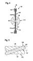
- FIG. 7 an alternative embodiment of both the first cleaning brush 126 and the second cleaning brush 128 shown in the form of a ring brush 152.
- This includes a plurality of radially to the longitudinal axis 147 of the drill 115 extending bristles 153, which are held on a retaining ring 154.
- the first cleaning brush 126 like the second cleaning brush 128, can be designed in the form of the ring brush 152, which can be penetrated by the drill 115.
- a cover 156 On the second cleaning brush 128 side facing the first cleaning brush 126 is covered by a cover 156. This is designed as a flexible rubber membrane in the form of the jacket of a truncated cone, which can be penetrated centrally by the drill 115. By means of the cover 156, drilling debris is guided radially outward relative to the longitudinal axis 147. If the drill 115 is pulled out of the second housing chamber 92, so by means of the cover 156 in combination with the first cleaning brush 126 ensures that the drill 115 is stripped and thus removed at this adhering Bohrschmutz, while ensuring that no Bohrschmutz on the rear housing opening 113 can escape from the housing 77. This is especially true for vertical alignment of the drill 115, that is, when introducing a hole in a ceiling. Also in this case, all the drilling dust produced during drilling is collected within the second housing chamber 92.
- the Bohrschmutzauffangs worn 110 can be reliably held by sucking the gap 103 on the ground 80 for introducing a hole in the substrate 80th
- the diaphragm pump 96 remains turned on. After a bore has been introduced into the substrate 80, the drill 115 can be pulled out of the second housing chamber 92, and then the diaphragm pump 96 can be switched off by means of the switching member 98. It can then be briefly actuated the switching plunger 95, so that the gap 103 is vented and the housing 77 can be removed from the substrate 80.
- Bohrschmutzauffang worn 110 may be integrated into the housing 77 a known per se and therefore not shown in the drawing marking device, in particular a laser marking device, and a measuring device and a dragonfly.
- the measuring device By means of the measuring device, the desired position for a bore on the substrate 80 can be determined, and by means of the marking device, a marking can be made.
- the necessary attachment to the substrate 80 is carried out by the use of the diaphragm pump 96, so that the user has both hands free and, for example, with both hands, the drill 116 can keep safe.
Landscapes
- Engineering & Computer Science (AREA)
- Mechanical Engineering (AREA)
- General Engineering & Computer Science (AREA)
- Physics & Mathematics (AREA)
- General Physics & Mathematics (AREA)
- Brushes (AREA)
- Processing Of Stones Or Stones Resemblance Materials (AREA)
- Insertion Pins And Rivets (AREA)
- Earth Drilling (AREA)
Abstract
Description
Die Erfindung betrifft eine Befestigungseinrichtung zum lösbaren Befestigen eines Gegenstandes an einem Untergrund, insbesondere einer Wand oder einer Decke, mit einer Saugplatte, an der ein Dichtring gehalten ist zur Anlage an dem Untergrund, und mit einer elektrischen Vakuumpumpe, mit der ein vom Dichtring abdichtbarer Zwischenraum zwischen der Saugplatte und dem Untergrund mit Unterdruck beaufschlagbar ist.The invention relates to a fastening device for releasably securing an object to a substrate, in particular a wall or a ceiling, with a suction plate on which a sealing ring is held for engagement with the ground, and with an electric vacuum pump, with a sealable from the sealing ring gap between the suction plate and the substrate with negative pressure can be acted upon.
Mittels einer derartigen Befestigungseinrichtung kann ein Gegenstand, beispielsweise ein Messgerät, eine Markierungseinrichtung oder auch ein Schmutzauffanggerät, zeitweilig an einem Untergrund befestigt werden, insbesondere an einer Wand oder einer Decke. Hierzu kann die Saugplatte unter Zwischenlage des Dichtringes an den Untergrund angelegt werden, und anschließend kann mittels der Vakuumpumpe der Zwischenraum zwischen der Saugplatte und dem Untergrund abgesaugt werden und somit mit Unterdruck beaufschlagt werden. Dies hat zur Folge, dass die Saugplatte pneumatisch am Untergrund anhaftet.By means of such a fastening device, an object, for example a measuring device, a marking device or a dirt collecting device, temporarily be attached to a substrate, in particular on a wall or a ceiling. For this purpose, the suction plate can be applied with the interposition of the sealing ring to the substrate, and then can be sucked by means of the vacuum pump, the space between the suction plate and the substrate and thus subjected to negative pressure. This has the consequence that the suction plate pneumatically adheres to the substrate.
Aus der
Die bekannte Befestigungseinrichtung ist unhandlich und schwer und erfordert die Bereitstellung einer Netzspannung, an die die elektrische Vakuumpumpe mittels eines Anschlusskabels angeschlossen werden kann.The known fastening device is unwieldy and heavy and requires the provision of a mains voltage to which the electric vacuum pump can be connected by means of a connecting cable.
Aufgabe der vorliegenden Erfindung ist es, eine Befestigungseinrichtung der eingangs genannten Art derart weiterzubilden, dass sie unabhängig von einer Netzspannung betrieben werden kann und einfacher zu handhaben ist.Object of the present invention is to provide a fastening device of the type mentioned in such a way that it can be operated independently of a mains voltage and is easier to handle.
Diese Aufgabe wird bei einer Befestigungseinrichtung der gattungsgemäßen Art erfindungsgemäß dadurch gelöst, dass die Saugplatte in ein Gehäuse integriert ist, das die Vakuumpumpe, eine Batterie sowie ein elektrisches Schaltorgan zum Ein- und Ausschalten der Vakuumpumpe aufnimmt.This object is achieved in a fastening device of the generic type according to the invention that the suction plate is integrated into a housing which receives the vacuum pump, a battery and an electrical switching element for switching on and off the vacuum pump.
Die erfindungsgemäße Befestigungseinrichtung bildet ein autarkes Gerät aus, mit dem ein Gegenstand zeitweilig an einem Untergrund, insbesondere einer Wand oder einer Decke, befestigt werden kann, ohne dass eine Netzspannung und ein Anschlusskabel bereitgestellt werden müssen. Dies ermöglicht es insbesondere, die Befestigungseinrichtung in Räumen ohne Netzanschluss zu betreiben, beispielsweise in einem Rohbau. Außerdem zeichnet sich die erfindungsgemäße Befestigungseinrichtung durch eine einfache Handhabung aus, denn sämtliche Bauteile der Befestigungseinrichtung sind in das Gehäuse integriert, das beispielsweise quaderförmig oder zylinderförmig ausgestaltet sein kann und vom Benutzer auf einfache Weise ergriffen werden kann. Durch Betätigung des elektrischen Schaltorganes kann die im Gehäuse angeordnete Vakuumpumpe in Gang gesetzt werden, deren elektrische Energie von der ebenfalls im Gehäuse angeordneten, vorzugsweise wiederaufladbaren Batterie bereitgestellt wird. Mittels der Vakuumpumpe kann bei am Untergrund angelegtem Gehäuse der Zwischenraum zwischen der Saugplatte des Gehäuses und dem Untergrund abgesaugt werden, so dass das Gehäuse pneumatisch am Untergrund anhaftet. Das Anhaften erfolgt solange wie die Vakuumpumpe in Betrieb ist. Wird sie mittels des elektrischen Schaltorganes ausgeschaltet, so kann aufgrund von Leckagen eine Belüftung des Zwischenraumes erfolgen, so dass das Gehäuse auf einfache Weise vom Benutzer wieder vom Untergrund gelöst werden kann.The fastening device according to the invention forms a self-sufficient device, with which an object can be temporarily attached to a substrate, in particular a wall or a ceiling, without having to provide a mains voltage and a connecting cable. This makes it possible in particular to operate the fastening device in rooms without mains connection, for example in a shell. In addition, the fastening device according to the invention is characterized by a simple handling, because all components of the fastening device are integrated into the housing, which may be configured, for example, cuboid or cylindrical and can be taken by the user in a simple manner. By operating the electrical switching element arranged in the housing Vacuum pump can be set in motion, the electrical energy of which is also provided in the housing, preferably rechargeable battery is provided. By means of the vacuum pump, the intermediate space between the suction plate of the housing and the substrate can be sucked off when the housing is applied to the substrate so that the housing adheres pneumatically to the substrate. The adhesion takes place as long as the vacuum pump is in operation. If it is switched off by means of the electrical switching device, it can be due to leaks ventilation of the gap, so that the housing can be solved in a simple way by the user again from the ground.
Die erfindungsgemäße Befestigungseinrichtung ist kostengünstig herstellbar. Hierzu ist es von Vorteil, wenn die Vakuumpumpe in Form einer Membranpumpe ausgestaltet ist.The fastening device according to the invention is inexpensive to produce. For this purpose, it is advantageous if the vacuum pump is designed in the form of a diaphragm pump.
Bei einer vorteilhaften Ausführungsform umfasst die Befestigungseinrichtung ein Verbindungselement zum lösbaren Verbinden eines Gegenstandes mit dem Gehäuse. So kann beispielsweise in das Gehäuse eine Durchgangsöffnung eingeformt sein, in die ein Halteorgan des Gegenstandes, insbesondere ein Haltebügel, eingesetzt werden kann. Alternativ oder ergänzend kann vorgesehen sein, dass das Verbindungselement eine Aufnahme umfasst zum formschlüssigen Verbinden des Gehäuses mit dem Gegenstand.In an advantageous embodiment, the fastening device comprises a connecting element for releasably connecting an object to the housing. Thus, for example, be formed in the housing, a passage opening into which a holding member of the object, in particular a headband, can be used. Alternatively or additionally, it may be provided that the connecting element comprises a receptacle for the positive connection of the housing with the object.
Die Aufnahme kann beispielsweise als T-förmige oder schwalbenschwanzförmige Nut ausgebildet sein, in die eine korrespondierend ausgebildete Leiste des Gegenstandes eingeführt werden kann. Dies ermöglicht eine lösbare Verbindung des Gehäuses mit dem Gegenstand und hat den Vorteil, dass unterschiedliche Gegenstände mit dem Gehäuse der Befestigungseinrichtung verbunden werden können. So kann beispielsweise vorgesehen sein, dass das Gehäuse mit einer Positionsbestimmungseinrichtung, einer Messeinrichtung, beispielsweise einem aufrollbaren Maßband, und/oder mit einer Markierungseinrichtung, beispielsweise einer Lasermarkierungseinrichtung, verbunden werden kann. Dies gibt zum Beispiel die Möglichkeit, eine bestimmte Position eines Bohrloches, das in den Untergrund eingebracht werden soll, auszumessen und zu markieren. Vorzugsweise ist das Gehäuse auch mit einer Bohrschmutzauffangeinrichtung verbindbar, die von einem Bohrer zum Einbringen einer Bohrung in den Untergrund durchgriffen werden kann und der Aufnahme des beim Bohren anfallenden Bohrschmutzes dient.The receptacle can be designed, for example, as a T-shaped or dovetail-shaped groove into which a correspondingly formed strip of the object can be inserted. This allows a detachable connection of the housing with the object and has the advantage that different Objects can be connected to the housing of the fastening device. For example, it may be provided that the housing can be connected to a position-determining device, a measuring device, for example a roll-up measuring tape, and / or to a marking device, for example a laser marking device. This gives, for example, the ability to measure and mark a specific position of a borehole to be placed in the ground. Preferably, the housing is also connectable to a Bohrschmutzauffangeinrichtung, which can be penetrated by a drill for introducing a hole in the ground and serves to receive the drilling dirt accumulating during drilling.
Als mit dem Gehäuse lösbar verbindbarer Gegenstand kann auch eine Libelle zum Einsatz kommen zum horizontalen und/oder vertikalen Ausrichten der Befestigungseinrichtung an einer Wand oder einer Decke.As a releasably connectable to the housing object, a dragonfly can be used for horizontal and / or vertical alignment of the fastening device to a wall or a ceiling.
Alternativ oder ergänzend kann als Verbindungselement auch ein Klebekissen zum Einsatz kommen, das am Gehäuse gehalten ist und vorzugsweise von einer abziehbaren Schutzfolie bedeckt ist. Mittels des Klebekissens kann ein temporär am Untergrund zu befestigender Gegenstand mit dem Gehäuse der Befestigungseinrichtung lösbar verklebt werden.Alternatively or additionally, a bonding pad can also be used as the connecting element, which is held on the housing and is preferably covered by a peelable protective film. By means of the adhesive pad, a temporary object to be fastened to the substrate can be adhesively bonded to the housing of the fastening device.
Der an der Saugplatte gehaltene Dichtring ist bevorzugt aus einem elastisch verformbaren Material gefertigt. Günstig ist es, wenn er an leicht gekrümmte Oberflächen des Untergrundes anpassbar und spaltfüllend ist, so dass der vom Dichtring umgebene Bereich der Saugplatte luftdicht abgedichtet werden kann, wenn die Saugplatte unter Zwischenschaltung des Dichtringes an den Untergrund angelegt wird.The seal held on the suction plate is preferably made of an elastically deformable material. It is favorable if it is adaptable to slightly curved surfaces of the substrate and gap-filling, so that the region surrounded by the sealing ring of the suction plate can be sealed airtight, if the suction plate is applied to the substrate with the interposition of the sealing ring.
Wie bereits erläutert, lässt sich die Befestigungseinrichtung pneumatisch an einem Untergrund festlegen, indem der vom Dichtring abgedichtete Zwischenraum zwischen der Saugplatte und dem Untergrund mittels der Vakuumpumpe abgesaugt wird. Zum Abnehmen der Befestigungseinrichtung vom Untergrund ist es in vielen Fällen ausreichend, die Vakuumpumpe auszuschalten, da dann aufgrund von Leckagen der Zwischenraum belüftet wird. Bei einer Befestigung an einem glatten Untergrund ist es allerdings von Vorteil, wenn die Befestigungseinrichtung ein Belüftungselement aufweist zum Belüften des Zwischenraumes. Der glatte Untergrund kann zur Folge haben, dass der Zwischenraum beim Ausschalten der Vakuumpumpe nur langsam aufgrund von Leckagen belüftet wird. Mit Hilfe des Belüftungselementes kann jedoch der Zwischenraum innerhalb sehr kurzer Zeit belüftet werden, so dass der Unterdruck im Zwischenraum entfällt und folglich die Befestigungseinrichtung auf einfache Weise vom Untergrund entfernt werden kann.As already explained, the fastening device can be pneumatically fixed to a substrate by the suction space sealed by the sealing ring between the suction plate and the substrate is sucked by means of the vacuum pump. To remove the fastening device from the ground, it is sufficient in many cases to turn off the vacuum pump, since then the gap is vented due to leaks. When mounted on a smooth surface, however, it is advantageous if the fastening device has a ventilation element for venting the gap. The smooth surface may cause the gap to be vented slowly due to leakage when the vacuum pump is turned off. With the help of the ventilation element, however, the gap can be ventilated within a very short time, so that the negative pressure in the intermediate space is eliminated and thus the fastening device can be easily removed from the ground.
Das Belüftungselement kann elektrisch betätigbar sein. Insbesondere kann vorgesehen sein, dass das Belüftungselement mit der Vakuumpumpe gekoppelt ist dergestalt, dass das Belüftungselement den Zwischenraum belüftet, wenn die Vakuumpumpe abgeschaltet wird.The ventilation element can be electrically actuated. In particular, it can be provided that the ventilation element is coupled to the vacuum pump such that the ventilation element ventilates the intermediate space when the vacuum pump is switched off.
Bei einer konstruktiv besonders einfachen und kostengünstig herstellbaren Ausführungsform ist das Belüftungselement manuell betätigbar. Es kann somit vom Benutzer zum Belüften des Zwischenraumes betätigt werden.In a structurally particularly simple and inexpensive to produce embodiment, the ventilation element is manually operable. It can thus be operated by the user to ventilate the gap.
Es kann beispielsweise vorgesehen sein, dass das Belüftungselement ein federelastisch in eine Schließstellung vorgespanntes Belüftungsventil umfasst. Mittels des Belüftungsventiles kann eine Strömungsverbindung zwischen dem Zwischenraum und der Umgebung der Befestigungseinrichtung gesteuert werden. Im unbetätigten Zustand nimmt das Belüftungsventil aufgrund seiner Federbelastung eine Schließstellung ein, so dass die Strömungsverbindung zwischen dem Zwischenraum und der Umgebung unterbrochen ist. Zur Belüftung des Zwischenraumes wird der Schaltzustand des Belüftungsventiles geändert, so dass dieses in seine Offenstellung übergeht und dadurch der Zwischenraum belüftet werden kann.It can be provided, for example, that the ventilation element comprises a resiliently biased in a closed position ventilation valve. By means of the vent valve, a flow connection between the gap and the environment of the fastening device can be controlled. In the unactuated state, the vent valve assumes a closed position due to its spring load, so that the flow connection between the gap and the environment is interrupted. For ventilation of the gap of the switching state of the ventilation valve is changed so that it passes into its open position and thereby the gap can be ventilated.
Bei einer vorteilhaften Ausführungsform wirkt das Belüftungsventil mit einem manuell betätigbaren Schaltstößel zusammen. Durch Betätigung des Schaltstößels kann die Schaltstellung des Belüftungsventiles geändert werden, insbesondere kann das Belüftungsventil entgegen der Einwirkung einer Federkraft in seine Offenstellung überführt werden.In an advantageous embodiment, the ventilation valve cooperates with a manually operable switch plunger. By actuating the switch plunger, the switching position of the ventilation valve can be changed, in particular, the ventilation valve can be transferred against the action of a spring force in its open position.
Günstig ist es, wenn der Schaltstößel eine dem Untergrund abgewandte Rückwand des Gehäuses durchgreift und nach außen über die Rückwand vorsteht.It is advantageous if the switch plunger passes through a wall of the housing facing away from the background and protrudes outward beyond the rear wall.
Das Belüftungselement kann ebenso wie die Vakuumpumpe, die Batterie und das elektrische Schaltorgan innerhalb des Gehäuses angeordnet sein.The venting element may, like the vacuum pump, the battery and the electrical switching element, be arranged inside the housing.
Bei einer bevorzugten Ausführungsform bildet das Gehäuse der Befestigungseinrichtung einen Strömungskanal aus, der mit der Vakuumpumpe in Strömungsverbindung steht und in dem vom Dichtring umgebenen Bereich die Saugplatte durchgreift. Der Strömungskanal bildet zumindest einen Teil einer Saugleitung aus, über die der abzusaugende Zwischenraum mit der Vakuumpumpe in Strömungsverbindung steht.In a preferred embodiment, the housing of the fastening device forms a flow channel which is in flow communication with the vacuum pump and passes through the suction plate in the area surrounded by the sealing ring. The flow channel forms at least a part of a Suction line, via which the suctioned gap is in flow communication with the vacuum pump.
Es kann vorgesehen sein, dass der Strömungskanal über einen innerhalb des Gehäuses angeordneten flexiblen Saugschlauch mit der Vakuumpumpe verbunden ist. Die flexible Verbindung der Vakuumpumpe über den Saugschlauch mit dem starren Strömungskanal erleichtert das Einsetzen der Vakuumpumpe bei der Montage der Befestigungseinrichtung.It can be provided that the flow channel is connected to the vacuum pump via a flexible suction hose arranged inside the housing. The flexible connection of the vacuum pump via the suction hose with the rigid flow channel facilitates the insertion of the vacuum pump during assembly of the fastening device.
Von besonderem Vorteil ist es, wenn im Strömungskanal ein Filterelement angeordnet ist, vorzugsweise ist das Filterelement in den Strömungskanal einschiebbar. Mittels des Filterelementes kann vermieden werden, dass die Vakuumpumpe mit Schmutzpartikel in Kontakt kommt. Dadurch kann die Lebensdauer der Vakuumpumpe verlängert werden.It is particularly advantageous if a filter element is arranged in the flow channel, preferably the filter element can be inserted into the flow channel. By means of the filter element can be avoided that the vacuum pump comes into contact with dirt particles. This can extend the life of the vacuum pump.
Günstig ist es, wenn das Filterelement den Strömungskanal vollständig ausfüllt. Vorzugsweise weist das Filterelement ein Papierfilter auf, das in den Strömungskanal einsetzbar ist.It is advantageous if the filter element completely fills the flow channel. The filter element preferably has a paper filter which can be inserted into the flow channel.
Bei einer vorteilhaften Ausführungsform verläuft der Strömungskanal in einer Zwischenwand des Gehäuses. Durch die Zwischenwand kann die mechanische Belastbarkeit des Gehäuses erhöht werden und gleichzeitig kann mit ihrer Hilfe ein Strömungskanal bereitgestellt werden. Dies ermöglicht es, die Befestigungseinrichtung besonders kostengünstig herzustellen und zu montieren.In an advantageous embodiment, the flow channel extends in an intermediate wall of the housing. Through the intermediate wall, the mechanical strength of the housing can be increased and at the same time can be provided with their help a flow channel. This makes it possible to manufacture and mount the fastening device particularly cost-effectively.
Die Zwischenwand unterteilt bei einer vorteilhaften Ausführungsform das Gehäuse in zwei Gehäusekammern, wobei eine erste Gehäusekammer die Vakuumpumpe, die Batterie und das Schaltorgan aufnimmt. Sämtliche elektrischen Bauteile der Befestigungseinrichtung sind somit in der ersten Gehäusekammer angeordnet und dadurch vor Umwelteinflüssen geschützt. Bei Einsatz eines Belüftungselementes kann dieses ebenfalls in der ersten Gehäusekammer angeordnet sein. Vorzugsweise ist die erste Gehäusekammer dem Benutzer nach Entfernen eines Deckels zugänglich zum Austausch der Batterie, die bei einer besonders bevorzugten Ausführungsform wiederaufladbar ausgestaltet ist.The intermediate wall is divided in an advantageous embodiment, the housing in two housing chambers, wherein a first housing chamber the Vacuum pump, the battery and the switching device receives. All electrical components of the fastening device are thus arranged in the first housing chamber and thereby protected from environmental influences. When using a ventilation element this can also be arranged in the first housing chamber. Preferably, after removal of a cover, the first housing chamber is accessible to the user for replacement of the battery, which in a particularly preferred embodiment is designed to be rechargeable.
Es kann vorgesehen sein, dass eine zweite Gehäusekammer einen zu befestigenden Gegenstand aufnimmt. So kann beispielsweise vorgesehen sein, dass die zweite Gehäusekammer eine Aufnahme bildet, in die der temporär zu befestigende Gegenstand eingesetzt werden kann.It can be provided that a second housing chamber receives an object to be fastened. For example, it may be provided that the second housing chamber forms a receptacle into which the object to be temporarily fixed can be inserted.
Wie bereits erläutert, kann mittels der Befestigungseinrichtung beispielsweise eine Bohrschmutzauffangeinrichtung temporär an einem Untergrund, insbesondere einer Wand oder einer Decke, befestigt werden. Mittels der Bohrschmutzauffangeinrichtung kann während des Einbringens einer Bohrung in den Untergrund anfallender Bohrschmutz, also Bohrmaterial und Bohrstaub, aufgefangen werden. Hierzu ist bei einer besonders bevorzugten Ausführungsform der erfindungsgemäßen Befestigungseinrichtung vorgesehen, dass in die zweite Gehäusekammer eine Bohrschmutzauffangeinrichtung integriert ist und die zweite Gehäusekammer von einem Bohrer durchsetzbar ist zum Einbringen einer Bohrung in den Untergrund, wobei die zweite Gehäusekammer einen Bohrschmutzsammelraum definiert und mindestens eine Reinigungseinrichtung aufnimmt zum Abreinigen des Bohrers. Zum Einbringen einer Bohrung in den Untergrund kann das Gehäuse an den Untergrund angelegt und durch Einschalten der Vakuumpumpe an diesem pneumatisch festgelegt werden, wie dies voranstehend bereits erläutert wurde. Es kann dann ein drehfest an einer Bohrmaschine gehaltener Bohrer durch die zweite Gehäusekammer hindurchgeführt werden zum Einbringen einer Bohrung in den Untergrund. Anfallender Bohrschmutz wird vom Bohrer nach Art eines Schneckenförderers in den Innenraum der zweiten Gehäusekammer überführt und sammelt sich im Bohrschmutzsammelraum an. Zum Abreinigen des Bohrers während des Einbringens der Bohrung und/oder beim Herausziehen des Bohrers aus der zweiten Gehäusekammer nimmt diese zumindest eine Reinigungseinrichtung auf. Dadurch ist sichergestellt, dass der Bohrschmutz innerhalb des Bohrschmutzsammelraumes verbleibt und nicht in den Außenbereich des Gehäuses gelangt.As already explained, by means of the fastening device, for example, a Bohrschmutzauffanging device can be temporarily attached to a substrate, in particular a wall or a ceiling. By means of the Bohrschmutzauffangvorrichtung can be collected during the introduction of a hole in the ground accumulating Bohrschmutz, ie drilling material and Bohrstaub. For this purpose, it is provided in a particularly preferred embodiment of the fastening device according to the invention that in the second housing chamber a Bohrschmutzauffangeinrichtung is integrated and the second housing chamber is enforced by a drill for introducing a hole in the ground, said second housing chamber defines a Bohrschmutzsammelraum and at least receives a cleaning device for cleaning the drill. To insert a hole in the ground, the housing can be applied to the ground and be set pneumatically by turning on the vacuum pump on this, as already explained above. It can then be passed through a rotatably held on a drill drill through the second housing chamber for introducing a hole in the ground. Accumulating Bohrschmutz is transferred from the drill in the manner of a screw conveyor in the interior of the second housing chamber and accumulates in the Bohrschmutzsammelraum. To clean the drill during the introduction of the bore and / or when pulling out the drill from the second housing chamber this takes on at least one cleaning device. This ensures that the drilling debris remains within the Bohrschmutzsammelraumes and does not get into the outer area of the housing.
So kann beispielsweise vorgesehen sein, dass eine erste Reinigungseinrichtung zumindest eine den Bohrer beim Herausziehen aus der zweiten Gehäusekammer abstreifende erste Reinigungsbürste umfasst. Mittels der ersten Reinigungsbürste kann der Bohrer nach dem Einbringen einer Bohrung in den Untergrund abgestreift werden, während er aus der zweiten Gehäusekammer herausgezogen wird.For example, it may be provided that a first cleaning device comprises at least one first cleaning brush scraping off the drill when pulling it out of the second housing chamber. By means of the first cleaning brush, the drill can be stripped after the introduction of a hole in the ground, while it is pulled out of the second housing chamber.
Alternativ oder ergänzend zu der mindestens einen ersten Reinigungsbürste können flexible Reinigungselemente zum Einsatz kommen, beispielsweise Gummistreifen, die den Bohrer beim Herausziehen aus der zweiten Gehäusekammer abstreifen und somit von anhaftendem Bohrschmutz befreien.As an alternative or in addition to the at least one first cleaning brush, flexible cleaning elements may be used, for example rubber strips which strip the drill from the second housing chamber during extraction and thus free it from adhering drilling debris.
Bevorzugt ist eine erste Reinigungsbürste ringförmig ausgestaltet und vom Bohrer durchsetzbar. Damit ist auf konstruktiv einfache Weise sichergestellt, dass der am Bohrer entlang seines Umfanges anhaftende Bohrschmutz entfernt werden kann.Preferably, a first cleaning brush is designed annular and enforceable by the drill. This ensures a structurally simple way that the drilling debris adhering to the drill along its circumference can be removed.
Es kann auch vorgesehen sein, dass eine erste Reinigungsbürste als Doppelbürste ausgestaltet ist und zwei einander zugewandte Borstenreihen aufweist, die zwischen sich den Bohrer aufnehmen. Die Borstenreihen sind kostengünstig herstellbar, und durch den Einsatz zweier einander zugewandter Borstenreihen kann der Bohrer in Umfangsrichtung praktisch vollständig abgereinigt werden.It can also be provided that a first cleaning brush is designed as a double brush and has two facing bristle rows, which receive the drill between them. The bristle rows are inexpensive to produce, and by using two facing bristle rows of the drill can be virtually completely cleaned in the circumferential direction.
Bei einer vorteilhaften Ausführungsform weist die zweite Gehäusekammer zwei fluchtend zueinander angeordnete, vom Bohrer durchsetzbare Gehäuseöffnungen auf, wobei eine stirnseitige Gehäuseöffnung dem Untergrund zugewandt und eine rückseitige Gehäuseöffnung dem Untergrund abgewandt ist und wobei die erste Reinigungseinrichtung die rückseitige Gehäuseöffnung zumindest teilweise überdeckt. Dadurch ist sichergestellt, dass auch beim Einbringen einer Bohrung in eine Decke kein Bohrschmutz durch die zweite Gehäusekammer hindurch fallen kann, vielmehr wird sämtlicher Bohrschmutz innerhalb der zweiten Gehäusekammer von der ersten Reinigungseinrichtung zurückgehalten, die die rückseitige Gehäuseöffnung zumindest teilweise überdeckt und diese zusammen mit dem die zweite Gehäusekammer durchgreifenden Bohrer verschießt.In an advantageous embodiment, the second housing chamber has two mutually aligned, by the drill enforceable housing openings, wherein an end-side housing opening facing the ground and a rear housing opening facing away from the ground and wherein the first cleaning means covers the rear housing opening at least partially. This ensures that even when introducing a hole in a ceiling no Bohrschmutz can fall through the second housing chamber through, but all Bohrschmutz is retained within the second housing chamber of the first cleaning device, which covers the rear housing opening at least partially and this together with the second housing chamber sweeping drill shoots.
Günstig ist es, wenn die erste Reinigungseinrichtung der stirnseitigen Gehäuseöffnung zugewandt eine Abdeckung aufweist. Dadurch wird die Gefahr besonders gering gehalten, dass beim Einbringen einer Bohrung in eine Decke Bohrschmutz durch das Gehäuse hindurchfällt.It is favorable if the first cleaning device faces the front-side housing opening and has a cover. As a result, the risk is kept particularly low that when introducing a hole in a ceiling drilling debris falls through the housing.
Vorzugsweise ist die Abdeckung an den Außenumfang des Bohrers anlegbar.Preferably, the cover on the outer periphery of the drill can be applied.
Es kann vorgesehen sein, dass die Abdeckung aus einem flexiblen Material, beispielsweise einem gummiartigen Material, gefertigt ist. Insbesondere kann die Abdeckung in Form einer Membran ausgebildet sein.It can be provided that the cover is made of a flexible material, for example a rubber-like material. In particular, the cover may be in the form of a membrane.
Die Abdeckung überdeckt bei einer bevorzugten Ausführungsform der Erfindung die rückseitige Gehäuseöffnung.The cover covers in a preferred embodiment of the invention, the rear housing opening.
Als vorteilhaft hat es sich erwiesen, die Abdeckung kegelmantelförmig auszugestalten, denn dadurch kann auf konstruktiv einfache Weise Bohrschmutz in radialer Richtung vom Bohrer entfernt werden, der die Abdeckung zentral durchgreift.It has proven to be advantageous to design the cover cone-shaped, as this can be removed in a constructional simple way Bohrschmutz in the radial direction of the drill, which passes through the cover centrally.
Bei einer besonders bevorzugten Ausführungsform umfasst eine zweite Reinigungseinrichtung zumindest eine den rotierenden Bohrer beim Bohren abstreifende zweite Reinigungsbürste. Es gibt die Möglichkeit, während des Einbringens einer Bohrung in den Untergrund am Bohrer anhaftender Bohrschmutz von diesem zu entfernen und in den Bohrschmutzsammelraum zu überführen. Wie bereits erläutert, bildet der rotierende Bohrer einen Schneckenförderer aus, der den anfallenden Bohrschmutz aus dem Bohrloch heraus transportiert und in das Innere der zweiten Gehäusekammer überführt. In der zweiten Gehäusekammer wird der rotierende Bohrer von der mindestens einen zweiten Reinigungsbürste abgestreift und somit von Bohrschmutz befreit.In a particularly preferred embodiment, a second cleaning device comprises at least one second cleaning brush scraping off the rotating drill during drilling. There is the possibility during the introduction of a hole in the ground to remove drill bit adhering to the drill from the latter and to transfer it to the drilling dirt collecting space. As already explained, the rotary drill forms a screw conveyor, which transports the resulting drilling debris out of the borehole and transfers it to the interior of the second housing chamber. In the second housing chamber of the rotating drill is stripped from the at least one second cleaning brush and thus freed from Bohrschmutz.
Der kombinierte Einsatz einer ersten Reinigungsbürste, die den Bohrer beim Herausziehen aus der zweiten Gehäusekammer abstreift, und einer zweiten Reinigungsbürste, die den rotierenden Bohrer beim Einbringen einer Bohrung in den Untergrund abstreift, hat sich als besonders vorteilhaft erwiesen, um praktisch sämtlichen anfallenden Bohrschmutz aufzufangen und sicherzustellen, dass auch beim Herausziehen des Bohrers aus der zweiten Gehäusekammer kein Bohrschmutz entweichen kann.The combined use of a first cleaning brush, which wipes the drill when pulling out of the second housing chamber, and a second cleaning brush, which strips the rotating drill when introducing a hole in the ground, has proven to be particularly advantageous to absorb virtually all accumulating Bohrschmutz and To ensure that no drilling dirt can escape even when pulling out the drill from the second housing chamber.
Von Vorteil ist es, wenn die zweite Reinigungsbürste zwischen der ersten Reinigungsbürste und der stirnseitigen Gehäuseöffnung angeordnet ist. Bei einer derartigen Anordnung wird der rotierende Bohrer während des Bohrens zunächst von der zweiten Reinigungsbürste abgebürstet, insbesondere wird die mindestens eine wendelförmige Bohrnut des Bohrers von Bohrschmutz befreit. Bohrschmutzreste, die von der zweiten Reinigungsbürste nicht erfasst werden, werden in der Bohrnut vom rotierenden Bohrer zur ersten Reinigungsbürste überführt und von dieser abgebürstet. Die Reinigungswirkung der ersten Reinigungsbürste entfaltet sich somit nicht erst beim Herausziehen des Bohrers aus der zweiten Gehäusekammer sondern auch während des Bohrens. Dadurch wird eine optimale Abreinigung des Bohrers erzielt.It is advantageous if the second cleaning brush is arranged between the first cleaning brush and the frontal housing opening. In such an arrangement, the rotary drill is first brushed off during drilling by the second cleaning brush, in particular, the at least one helical bore of the drill is freed from Bohrschmutz. Drilling debris not covered by the second cleaning brush will be transferred from the rotating drill to the first cleaning brush in the drill hole and brushed off. The cleaning effect of the first cleaning brush thus unfolds not only when pulling out the drill from the second housing chamber but also during drilling. This achieves optimal cleaning of the drill.
Es kann vorgesehen sein, dass die zweite Reinigungsbürste ringförmig ausgestaltet und vom Bohrer durchsetzbar ist. Mittels der zweiten Reinigungsbürste wird der rotierende Bohrer bei einer derartigen Ausgestaltung in Umfangsrichtung von allen Seiten gleichzeitig abgebürstet. Insbesondere lässt sich dadurch auf konstruktiv einfache Weise mindestens eine Bohrnut, in der der Bohrschmutz aus dem Bohrloch herausgeführt wird, zuverlässig abreinigen.It can be provided that the second cleaning brush is configured annular and can be enforced by the drill. By means of the second cleaning brush, the rotary drill is brushed off in such a configuration in the circumferential direction from all sides simultaneously. In particular, this makes it possible in a structurally simple manner to reliably clean off at least one drilling groove in which the drilling debris is led out of the borehole.
Bei einer besonders vorteilhaften Ausführungsform weist eine zweite Reinigungsbürste zumindest eine Borstenreihe auf, die parallel oder in einem spitzen Winkel zur Bohrerlängsachse ausgerichtet ist. Der in der Bohrnut des Bohrers aus dem Bohrloch herausgeführte Bohrschmutz wird bei einer derartigen Ausgestaltung innerhalb der zweiten Gehäusekammer seitlich der zweiten Reinigungsbürste zugeführt und kann von dieser zuverlässig abgebürstet werden.In a particularly advantageous embodiment, a second cleaning brush on at least one row of bristles, which is aligned parallel or at an acute angle to the drill longitudinal axis. The drilling dirt led out of the borehole in the boring groove of the drill is fed laterally to the second cleaning brush within the second housing chamber in such a configuration and can be brushed off reliably therefrom.
Bevorzugt ist eine zweite Reinigungsbürste als Doppelbürste ausgebildet und weist zwei einander zugewandte Borstenreihen auf, die zwischen sich den Bohrer aufnehmen. Hierbei ist es von besonderem Vorteil, wenn die beiden Borstenreihen parallel oder in einem spitzen Winkel zur Bohrerlängsachse ausgerichtet sind. Eine derartige Ausrichtung ist allerdings nicht zwingend erforderlich, es kann auch vorgesehen sein, dass die beiden Borstenreihen eine Ausrichtung senkrecht zur Bohrerlängsachse aufweisen.Preferably, a second cleaning brush is designed as a double brush and has two facing bristle rows, which receive the drill between them. It is particularly advantageous if the two rows of bristles are aligned parallel or at an acute angle to the drill longitudinal axis. However, such an alignment is not absolutely necessary, it can also be provided that the two rows of bristles have an orientation perpendicular to the drill longitudinal axis.
Um zu vermeiden, dass sich während des Bohrens zwischen dem Untergrund und der Außenwand der zweiten Gehäusekammer Bohrschmutz ansammeln kann, ist bei einer besonders vorteilhaften Ausführungsform vorgesehen, dass die stirnseitige Gehäuseöffnung von einer Schmutzführungshülse durchgriffen ist. Mittels der Schmutzführungshülse wird im Bereich der stirnseitigen Gehäuseöffnung Bohrschmutz zuverlässig in den Bohrschmutzsammelraum der zweiten Gehäusekammer überführt.In order to avoid that can accumulate during drilling between the substrate and the outer wall of the second housing chamber Bohrschmutz, is provided in a particularly advantageous embodiment that the frontal housing opening is penetrated by a dirt guide sleeve. By means of the dirt guide sleeve Bohrschmutz is reliably transferred in the Bohrschmutzsammelraum the second housing chamber in the region of the frontal housing opening.
Von besonderem Vorteil ist es, wenn die Schmutzführungshülse außenseitig über die zweite Gehäusekammer hervorsteht. Dies hat den Vorteil, dass die Schmutzführungshülse unmittelbar an den Untergrund angelegt werden kann.It is particularly advantageous if the dirt guide sleeve protrudes on the outside over the second housing chamber. This has the advantage that the dirt guide sleeve can be applied directly to the ground.
Günstig ist es, wenn die Schmutzführungshülse in ihrem nach außen vorstehenden Bereich von einem Dichtring umgeben ist. Letzterer ist vorzugsweise aus einem elastisch verformbaren Material gefertigt. Insbesondere kann er derart ausgestaltet sein, dass er an leicht gekrümmte Oberflächen des Untergrundes anpassbar und spaltfüllend ist, so dass der Bereich zwischen dem Bohrloch und der stirnseitigen Gehäuseöffnung der zweiten Gehäusekammer auch auf einem rauhen Untergrund zuverlässig staubdicht abgedichtet ist.It is advantageous if the dirt guide sleeve is surrounded in its outwardly projecting region by a sealing ring. The latter is preferably made of an elastically deformable material. In particular, it can be designed such that it is adaptable to slightly curved surfaces of the substrate and gap-filling, so that the area between the borehole and the frontal housing opening of the second housing chamber is reliably sealed dust-tight even on a rough surface.
Um zu vermeiden, dass beim Abnehmen der zweiten Gehäusekammer vom Untergrund über die stirnseitige Gehäuseöffnung Bohrschmutz entweichen kann, ist es von Vorteil, wenn die Schmutzführungshülse in die zweite Gehäusekammer hineinragt. Sie bildet dadurch einen von der stirnseitigen Gehäuseöffnung nach innen vorstehenden Kragen, der innerhalb der zweiten Gehäusekammer angesammelten Bohrschmutz in der zweiten Gehäusekammer zurückhält.In order to avoid that when removing the second housing chamber from the substrate via the frontal housing opening Bohrschmutz can escape, it is advantageous if the dirt guide sleeve protrudes into the second housing chamber. It thereby forms from the frontal housing opening inwardly projecting collar, which retains accumulated within the second housing chamber Bohrschmutz in the second housing chamber.
Von Vorteil ist es, wenn sich die Schmutzführungshülse in das Innere der zweiten Gehäusekammer konisch erweitert. Dadurch ist sichergestellt, dass der sich auf der Schmutzführungshülse ablagernde Bohrschmutz selbsttätig an der Schmutzführungshülse entlang gleitet und somit in den Innenraum der zweiten Gehäusekammer überführt wird.It is advantageous if the dirt guide sleeve widens conically into the interior of the second housing chamber. This ensures that the drilling debris depositing on the dirt guide sleeve automatically slides along the dirt guide sleeve and is thus transferred into the interior of the second housing chamber.
Die Schmutzführungshülse ist bei einer vorteilhaften Ausführungsform aus Metall gefertigt, insbesondere aus gehärtetem Metall.The dirt guide sleeve is made in an advantageous embodiment of metal, in particular of hardened metal.
Günstig ist es, wenn die Schmutzführungshülse an der zweiten Gehäusekammer auswechselbar gehalten ist, denn dies gibt die Möglichkeit, die Schmutzführungshülse auf einfache Weise auszuwechseln.It is advantageous if the dirt guide sleeve is held replaceable on the second housing chamber, because this gives the possibility to replace the dirt guide sleeve in a simple manner.
Bei einer vorteilhaften Ausführungsform ist die rückseitige Gehäuseöffnung von einer Führungsbuchse durchgriffen. Mittels der Führungsbuchse wird das Einführen des Bohrers in die zweite Gehäusekammer und auch dessen Ausrichtung beim Bohren vereinfacht.In an advantageous embodiment, the rear housing opening is penetrated by a guide bush. By means of the guide bush, the insertion of the drill into the second housing chamber and also its orientation during drilling is simplified.
Von Vorteil ist es hierbei, wenn die Führungsbuchse an der rückseitigen Gehäuseöffnung auswechselbare gehalten ist, denn dies gibt die Möglichkeit, in Abhängigkeit vom Durchmesser des zum Einsatz kommenden Bohrers eine entsprechend angepasste Führungsbuchse an der rückseitigen Gehäuseöffnung festzulegen.It is advantageous in this case if the guide bush is held replaceable on the rear housing opening, because this gives the possibility, depending on the diameter of the drill used to set a correspondingly adapted guide bushing on the rear housing opening.
Die Führungsbuchse ist günstigerweise aus Metall gefertigt, insbesondere aus gehärtetem Metall.The guide bush is conveniently made of metal, in particular of hardened metal.
Es kann vorgesehen sein, dass der lichte Durchmesser der Führungsbuchse dem lichten Durchmesser der Schmutzführungshülse entspricht. Dadurch wird das Ausrichten des Bohrers bei Einbringen einer Bohrung in den Untergrund vereinfacht.It can be provided that the clear diameter of the guide bush corresponds to the clear diameter of the dirt guide sleeve. This simplifies the alignment of the drill when inserting a hole in the ground.
Von Vorteil ist es, wenn die Führungsbuchse nach außen aus der zweiten Gehäusekammer herausragt. Sie kann in diesem herausragenden Bereich einen Bund ausbilden, mit dem sie außenseitig an die zweite Gehäusekammer anlegbar ist.It is advantageous if the guide bush protrudes outward from the second housing chamber. It can form a collar in this outstanding area, with which it can be applied to the outside of the second housing chamber.
Vorzugsweise ragt die Führungsbuchse nach innen in die zweite Gehäusekammer hinein. Sie kann im Innern der Gehäusekammer einen von der rückseitigen Gehäuseöffnung abstehenden Kragen ausbilden, der die Gefahr vermindert, dass beim Abnehmen der zweiten Gehäusekammer vom Untergrund Bohrschmutz aus der zweiten Gehäusekammer über die rückseitige Gehäuseöffnung entweichen kann.Preferably, the guide bush projects inwardly into the second housing chamber. It can form a protruding from the rear housing opening collar inside the housing chamber, which reduces the risk that when removing the second housing chamber from the ground Bohrschmutz can escape from the second housing chamber via the rear housing opening.
Zum Abreinigen des Bohrers kann ergänzend oder alternativ zu der ersten oder zweiten Reinigungsbürste auch eine Turbine zum Einsatz kommen. Die Turbine kann in der ersten oder der zweiten Gehäusekammer angeordnet sein und während des Einbringens einer Bohrung den Bohrer innerhalb des Gehäuses absaugen oder abblasen.To clean the drill, in addition to or as an alternative to the first or second cleaning brush, a turbine can also be used. The turbine may be disposed in the first or second housing chamber and, while drilling a bore, may aspirate or deflate the drill within the housing.
Die nachfolgende Beschreibung vorteilhafter Ausführungsformen der Erfindung dient im Zusammenhang mit der Zeichnung der näheren Erläuterung. Es zeigen:
- Figur 1:
- eine schematische Schnittansicht einer ersten Ausführungsform einer Befestigungseinrichtung;
- Figur 2:
- eine schematische Schnittansicht einer zweiten Ausführungsform einer Befestigungseinrichtung;
- Figur 3:
- eine schematische Schnittansicht einer dritten Ausführungsform einer Befestigungseinrichtung mit integrierter Bohrschmutzauffang einrichtung;
- Figur 4:
- eine Schnittansicht einer zweiten Reinigungsbürste der Bohrschmutzauffangeinrichtung entlang der Linie 4-4 in
Figur 3 ; - Figur 5:
- eine Ansicht der zweiten Reinigungsbürste in Richtung von Pfeil
A aus Figur 4 ; - Figur 6:
- eine Schnittansicht einer ersten Reinigungsbürste der Bohrschmutzauffangeinrichtung längs der Linie 6-6 in
Figur 3 und - Figur 7:
- eine Schnittansicht einer alternativen Ausgestaltung einer ersten und/oder zweiten Reinigungsbürste der Bohrschmutzauffangeinrichtung aus
Figur 3 .
- FIG. 1:
- a schematic sectional view of a first embodiment of a fastening device;
- FIG. 2:
- a schematic sectional view of a second embodiment of a fastening device;
- FIG. 3:
- a schematic sectional view of a third embodiment of a fastening device with integrated Bohrschmutzauffang device;
- FIG. 4:
- a sectional view of a second cleaning brush the Bohrschmutzauffangseinrichtung along the line 4-4 in
FIG. 3 ; - FIG. 5:
- a view of the second cleaning brush in the direction of arrow A from
FIG. 4 ; - FIG. 6:
- a sectional view of a first cleaning brush the Bohrschmutzauffangseinrichtung along the line 6-6 in
FIG. 3 and - FIG. 7:
- a sectional view of an alternative embodiment of a first and / or second cleaning brush of Bohrschmutzauffangseinrichtung
FIG. 3 ,
In
In die Deckenwand 17 ist ein Strömungskanal 22 eingeformt, der die Stirnwand 18 durchgreift und vollständig von einem Filterelement 23 ausgefüllt ist.In the
Über einen flexiblen Saugschlauch 25 steht der Strömungskanal 22 mit einer elektrischen Membranpumpe 26 in Strömungsverbindung, die innerhalb des Gehäuses 12 angeordnet ist und die mit einer elektrischen Batterie 27 verbunden ist und über ein Verbindungskabel 28 mit einem im Gehäuse 12 angeordneten elektromechanischen Schaltorgan 29 in elektrischer Verbindung steht, das ein die Rückwand 19 durchgreifendes Betätigungselement 30 aufweist.Via a
In die Stirnwand 18 ist eine Belüftungsöffnung 35 eingeformt, an der innenseitig ein Belüftungselement in Form eines Belüftungsventils 37 gehalten ist, das mittels eines Schaltstößels 38, der die Rückwand 19 durchgreift und innerhalb des Gehäuses 12 in einer Führungshülse 39 geführt ist, betätigt werden kann. Das Belüftungsventil 37 umfasst eine Schließfeder 41, die das Belüftungsventil 37 selbsttätig in seine Schließstellung vorspannt. Durch Drücken des Schaltstößels 38 kann der Benutzer das Belüftungsventil 37 entgegen der Wirkung der Schließfeder 41 in eine Offenstellung überführen, in der es eine Strömungsverbindung freigibt zwischen der Belüftungsöffnung 35 und einer in die Bodenwand 16 eingeformten Durchgangsöffnung 45.In the
Oberseitig bildet das Gehäuse 12 eine wannenförmige Aufnahme 32 aus, in die ein Klebekissen 33 eingesetzt ist, das von einer abziehbaren Schutzfolie 34 überdeckt ist.On the upper side, the
Soll ein Gegenstand, beispielsweise eine Messeinrichtung, eine Markierungseinrichtung oder ein sonstiges Objekt zeitweilig am Untergrund 14 befestigt werden, so kann hierzu das Gehäuse 12 an den Untergrund 14 angelegt werden, und durch Betätigen des Schaltorganes 29 kann die Membranpumpe 26 in Gang gesetzt werden, so dass ein vom Dichtring 13 luftdicht abgedichteter Zwischenraum 36 zwischen der Stirnwand 18 und dem Untergrund 14 abgesaugt und somit mit Unterdruck beaufschlagt wird. Aufgrund des sich ausbildenden Unterdruckes haftet die Befestigungseinrichtung 10 am Untergrund 14, ohne dass dieser beschädigt wird. Ein temporär zu befestigender Gegenstand kann nun durch Ablösen der Schutzfolie 34 mit dem Klebekissen 33 verbunden werden, so dass er über das Klebekissen 33 am Gehäuse 12 zuverlässig gehalten ist.If an object, such as a measuring device, a marking device or any other object temporarily be attached to the
Soll die Befestigungseinrichtung 10 wieder vom Untergrund 14 entfernt werden, so wird hierzu die Membranpumpe 26 abgeschaltet und kurzzeitig der Schaltstößel 38 betätigt, so dass der Zwischenraum 36 über die Belüftungsöffnung 35, den Innenraum des Gehäuses 12 und die Durchgangsöffnung 45 belüftet wird. Die Befestigungseinrichtung 10 kann dann vom Benutzer wieder vom Untergrund 14 entfernt werden.If the
In
Das Gehäuse 42 weist außerdem eine Zwischenwand 52 auf, die doppelwandig ausgebildet ist und das Gehäuse 42 in eine erste Gehäusekammer 53 und eine zweite Gehäusekammer 54 unterteilt. Die Zwischenwand 52 weist eine erste , der ersten Gehäusekammer 53 zugewandte Wandschicht 56 auf sowie eine zweite, der zweiten Gehäusekammer zugewandte Wandschicht 57, die parallel und im Abstand zueinander angeordnet sind und zwischen sich einen Strömungskanal 59 definieren, der die Stirnwand 48 durchgreift und in den Zwischenraum 60 zwischen der Stirnwand 48 und dem Untergrund 44 einmündet.The
Die erste Gehäusekammer 53 nimmt eine Membranpumpe 62, eine Batterie 63 sowie ein elektrisches Schaltorgan 64 auf, das mit einem Betätigungselement 65 die Rückwand 49 durchgreift. Über ein Verbindungskabel 66 steht das Schaltorgan 64 mit der Membranpumpe 62 in elektrischer Verbindung, und mittels eines flexiblen Saugschlauches 68 wird innerhalb der ersten Gehäusekammer 53 eine Strömungsverbindung hergestellt zwischen der Membranpumpe 62 und dem Strömungskanal 59. Der Strömungskanal 59 ist vollständig von einem Filterelement 61 ausgefüllt.The
Außerdem nimmt die erste Gehäusekammer 53 ein Belüftungsventil 55 auf, das eine Strömungsverbindung zwischen einer Belüftungsöffnung 58 der Stirnwand 48 und einer in die Bodenwand 46 eingeformten Durchgangsöffnung 67 steuert. Entsprechend dem voranstehend unter Bezugnahme auf die
In die Deckenwand 47 ist eine schwalbenschwanzförmige Nut 70 eingeformt, die eine Aufnahme ausbildet zum formschlüssigen Verbinden eines temporär am Untergrund 44 zu befestigenden Gegenstandes mit dem Gehäuse 42.In the
Soll ein Gegenstand mittels der Befestigungseinrichtung 40 temporär am Untergrund 44 befestigt werden, so kann er mit einer komplementär zur Nut 70 ausgestalteten Leiste durch Einführen derselben in die Nut 70 mit dem Gehäuse 42 lösbar verbunden werden. Das Gehäuse 42 kann dann mit der Stirnwand 48 an den Untergrund 44 angelegt werden, und durch Einschalten der Membranpumpe 62 kann der Zwischenraum 60 abgesaugt werden, so dass das Gehäuse 42 pneumatisch am Untergrund 44 anhaftet, so lange die Membranpumpe 62 in Betrieb ist. Wird die Membranpumpe 62 vom Benutzer ausgeschaltet und der Schaltstößel 69 betätigt, so baut sich der Unterdruck im Zwischenraum 60 aufgrund der Belüftung über das Belüftungsventil 55 ab und das Gehäuse 42 kann wieder vom Untergrund 44 entfernt werden.If an object is to be fastened temporarily to the
In den
Durch die Zwischenwand 87 wird das Gehäuse 77 in eine erste Gehäusekammer 91 und eine zweite Gehäusekammer 92 unterteilt, und zwischen der ersten Wandschicht 88 und der zweiten Wandschicht 89 verläuft ein Strömungskanal 93, der ein Filterelement 94 aufnimmt und in dem vom Dichtring 78 umgebenen Bereich die Stirnwand 84 durchgreift.By the
Die erste Gehäusekammer 91 nimmt eine Membranpumpe 96, eine Batterie 97 und ein elektromechanisches Schaltorgan 98 mit einem Betätigungselement 99 auf, wobei das Schaltorgan 98 über ein Verbindungskabel 100 elektrisch mit der Membranpumpe 96 verbunden ist und die Membranpumpe 96 über einen flexiblen Saugschlauch 101 mit dem Strömungskanal 93 in Strömungsverbindung steht. Außerdem nimmt die erste Gehäusekammer 91 ein Belüftungsventil 86 auf, das innenseitig an einer Belüftungsöffnung 90 der Stirnwand 84 angeordnet ist und vom Benutzer über einen Schaltstößel 95 betätigt werden kann. Das Belüftungsventil 86 nimmt aufgrund des Einsatzes einer Schließfeder selbsttätig seine Schließstellung ein, in der es eine Strömungsverbindung zwischen der Belüftungsöffnung 90 und einer in die Bodenwand 82 eingeformten Durchgangsöffnung 81 unterbricht. Durch Betätigen des Schaltstößels 95 kann der Benutzer das Belüftungsventil 86 in seine Offenstellung überführen.The
Im Bereich des Dichtringes 78 bildet die Stirnwand 84 eine Saugplatte 102 aus, an deren Außenseite der Dichtring 78 gehalten ist und die zusammen mit dem Untergrund 80 einen Zwischenraum 103 begrenzt, der von der Membranpumpe 96 über den Saugschlauch 101 und den Strömungskanal 93 abgesaugt werden kann, so dass das Gehäuse 77 pneumatisch am Untergrund 80 anhaftet. Soll der Zwischenraum 103 belüftet werden, so kann hierzu der Benutzer den Schaltstößel 95 betätigen, so dass das Belüftungsventil 86 in seine Offenstellung übergeht und dadurch der Zwischenraum 103 über die Belüftungsöffnung 90 belüftet werden kann.In the region of the sealing
Während die in den
Die stirnseitige Gehäuseöffnung 112 ist von einer auswechselbaren Schmutzführungshülse 118 durchgriffen, die sich in Richtung auf das Innere der zweiten Gehäusekammer 92 konisch erweitert und nach innen und nach außen über die Stirnwand 84 hervorsteht. In ihrem nach außen vorstehenden Bereich ist die Schmutzführungshülse 118 von einem flexiblen, elastisch verformbaren Dichtring 119 umgeben, der unmittelbar an den Untergrund 80 anlegbar ist. Die rückseitige Gehäuseöffnung 113 ist von einer Führungsbuchse 121 durchgriffen, die ebenso wie die Schmutzführungshülse 118 aus gehärtetem Metall gefertigt ist und die an der rückseitigen Gehäuseöffnung 113 auswechselbar gehalten ist. Sie kann in die rückseitige Gehäuseöffnung 113 eingesetzt werden, wobei sie mit einem auskragenden Bund 122 außenseitig an der Rückwand 113 des Gehäuses 77 anliegt.The front-
Die zweite Gehäusekammer 92 definiert in ihrem Inneren einen Bohrschmutzsammelraum 124 und nimmt eine erste Reinigungseinrichtung in Form einer ersten Reinigungsbürste 126 und eine zweite Reinigungseinrichtung in Form einer zweiten Reinigungsbürste 128 auf. Mittels der ersten Reinigungsbürste 126 wird der Bohrer 115 beim Herausziehen aus der zweiten Gehäusekammer 92 abgestreift, und mittels der zweiten Reinigungsbürste 128 kann der rotierende Bohrer beim Einbringen einer Bohrung in den Untergrund 80 abgereinigt werden. Die zweite Reinigungsbürste 128 ist zwischen der ersten Reinigungsbürste 126 und der stirnseitigen Gehäuseöffnung 112 angeordnet, die erste Reinigungsbürste 126 ist der rückseitigen Gehäuseöffnung 113 benachbart positioniert.The
Wie insbesondere aus
Wie aus
Während die Borstenreihen 131, 132 der ersten Reinigungsbürste 126 senkrecht zur Längsachse 147 des Bohrers 115 ausgerichtet sind, verlaufen die Borstenreihen 141, 142 der zweiten Reinigungsbürste 128 in einem spitzen Winkel zur Längsachse 147. Dies hat zur Folge, dass den Borstenreihen 141, 142 der Bohrschmutz vom rotierenden Bohrer 115 beim Einbringen einer Bohrung in den Untergrund 80 seitlich zugeführt wird, so dass er mittels der Borsten 145 ungefähr in Längsrichtung der Bohrnuten 136, 137 aus diesen herausgebürstet werden kann. Mittels der zweiten Reinigungsbürste 128 kann somit während des Einsatzes des Bohrers 115 Bohrschmutz zuverlässig von diesem entfernt werden. Der Bohrschmutz sammelt sich im Bohrschmutzsammelraum 124 an, und über eine Deckenöffnung 149, die von einem Deckel 150 verschließbar ist, kann der Bohrschmutzsammelraum 124 der zweiten Gehäusekammer 92 entleert werden.While the rows of
In
Auf der der zweiten Reinigungsbürste 128 zugewandten Seite ist die erste Reinigungsbürste 126 von einer Abdeckung 156 abgedeckt. Diese ist als flexible Gummimembran ausgebildet in Form des Mantels eines Kegelstumpfes, der zentral vom Bohrer 115 durchgriffen werden kann. Mittels der Abdeckung 156 wird Bohrschmutz bezogen auf die Längsachse 147 radial nach außen geführt. Wird der Bohrer 115 aus der zweiten Gehäusekammer 92 herausgezogen, so ist mittels der Abdeckung 156 in Kombination mit der ersten Reinigungsbürste 126 sichergestellt, dass der Bohrer 115 abgestreift und somit an diesem anhaftender Bohrschmutz entfernt wird, und gleichzeitig ist gewährleistet, dass kein Bohrschmutz über die rückseitige Gehäuseöffnung 113 aus dem Gehäuse 77 entweichen kann. Dies gilt insbesondere bei vertikaler Ausrichtung des Bohrers 115, das heißt bei Einbringen einer Bohrung in eine Decke. Auch in diesem Fall wird sämtlicher Bohrstaub, der beim Bohren anfällt, innerhalb der zweiten Gehäusekammer 92 gesammelt.On the
Wie bereits erläutert, kann die Bohrschmutzauffangeinrichtung 110 durch Absaugen des Zwischenraumes 103 zuverlässig am Untergrund 80 gehalten werden zum Einbringen einer Bohrung in den Untergrund 80. Während des Einbringens bleibt die Membranpumpe 96 eingeschaltet. Nachdem eine Bohrung in den Untergrund 80 eingebracht wurde, kann der Bohrer 115 aus der zweiten Gehäusekammer 92 herausgezogen werden, und anschließend kann die Membranpumpe 96 mittels des Schaltorganes 98 ausgeschaltet werden. Es kann dann kurzzeitig der Schaltstößel 95 betätigt werden, so dass der Zwischenraum 103 belüftet wird und das Gehäuse 77 vom Untergrund 80 entfernt werden kann.As already explained, the
Zusätzlich zur Bohrschmutzauffangeinrichtung 110 kann in das Gehäuse 77 eine an sich bekannte und deshalb in der Zeichnung nicht dargestellte Markierungseinrichtung, insbesondere eine Lasermarkierungseinrichtung, sowie eine Messeinrichtung und eine Libelle integriert sein. Mittels der Messeinrichtung kann die gewünschte Position für eine Bohrung am Untergrund 80 bestimmt werden, und mittels der Markierungseinrichtung kann eine Markierung vorgenommen werden. Die notwendige Befestigung am Untergrund 80 erfolgt durch den Einsatz der Membranpumpe 96, so dass der Benutzer jeweils beide Hände frei hat und beispielsweise mit beiden Händen die Bohrmaschine 116 sicher halten kann.In addition to the
Die Erfindung betrifft ferner die folgenden besonderen Ausführungsformen der Erfindung:
- 1. Befestigungseinrichtung zum lösbaren Befestigen eines Gegenstandes an einem Untergrund, mit einer Saugplatte, an der ein Dichtring gehalten ist zur Anlage am Untergrund, und mit einer elektrischen Vakuumpumpe, mit der ein vom Dichtring abdichtbarer Zwischenraum zwischen der Saugplatte und dem Untergrund mit Unterdruck beaufschlagbar ist, dadurch gekennzeichnet, dass die Saugplatte (18; 48; 102) in ein Gehäuse (12; 42; 77) integriert ist, das die Vakuumpumpe (26; 62; 96), eine Batterie (27; 63; 97) sowie ein elektrisches Schaltorgan (29; 64; 98) zum Ein- und Ausschalten der Vakuumpumpe (26; 62; 96) aufnimmt.
- 2. Befestigungseinrichtung nach Anspruch 1, dadurch gekennzeichnet, dass die Befestigungseinrichtung (10; 40) ein Verbindungselement (33; 70) zum lösbaren Verbinden eines Gegenstandes mit dem Gehäuse (12; 42) umfasst.
- 3. Befestigungseinrichtung nach Anspruch 2, dadurch gekennzeichnet, dass das Verbindungselement eine Aufnahme (70) umfasst zum formschlüssigen Verbinden des Gehäuses (42) mit dem Gegenstand.
- 4. Befestigungseinrichtung nach Anspruch 3, dadurch gekennzeichnet, dass die Aufnahme als T-förmige oder schwalbenschwanzförmige Nut (70) ausgebildet ist.
- 5. Befestigungseinrichtung nach einem der voranstehenden Ansprüche, dadurch gekennzeichnet, dass die Befestigungseinrichtung ein Belüftungselement (37; 55; 86) aufweist zum Belüften des Zwischenraums (36; 60; 103).
- 6. Befestigungseinrichtung nach Anspruch 5, dadurch gekennzeichnet, dass das Belüftungselement (37; 55; 86) manuell betätigbar ist.
- 7. Befestigungseinrichtung nach Anspruch 5
oder 6, dadurch gekennzeichnet, dass das Belüftungselement ein federelastisch in eine Schließstellung vorgespanntes Belüftungsventil (37; 55; 86) umfasst. - 8. Befestigungseinrichtung nach Anspruch 7, dadurch gekennzeichnet, dass das Belüftungsventil (37; 55; 86) mit einem manuell betätigbaren Schaltstößel (38; 69; 95) zusammenwirkt.
- 9. Befestigungseinrichtung nach einem der voranstehenden Ansprüche, dadurch gekennzeichnet, dass das Gehäuse (12; 42; 77) einen Strömungskanal (22; 59; 93) ausbildet, der mit der Vakuumpumpe (26; 62; 96) in Strömungsverbindung steht und in dem vom Dichtring (13; 43; 78) umgebenen Bereich die Saugplatte (18; 48; 102) durchgreift.
- 10. Befestigungseinrichtung nach Anspruch 9, dadurch gekennzeichnet, dass der Strömungskanal (22; 59; 93) über einen flexiblen Saugschlauch (25; 68; 101) mit der Vakuumpumpe (26; 62; 96) verbunden ist.
- 11. Befestigungseinrichtung nach Anspruch 9
oder 10, dadurch gekennzeichnet, dass im Strömungskanal (22; 59; 93) ein Filterelement (23; 61; 94) angeordnet ist. - 12. Befestigungseinrichtung nach Anspruch 11, dadurch gekennzeichnet, dass das Filterelement (23; 61; 94) den Strömungskanal (22; 59; 93) vollständig ausfüllt.
- 13. Befestigungseinrichtung nach einem der Ansprüche 9
bis 12, dadurch gekennzeichnet, dass der Strömungskanal (22; 59; 93) in einer Zwischenwand (17; 52; 87) des Gehäuses (12; 42; 77) verläuft. - 14.
Befestigungseinrichtung nach Anspruch 13, dadurch gekennzeichnet, dass die Zwischenwand (52; 87) das Gehäuse (42; 77) in zwei Gehäusekammern (53, 54; 91, 92) unterteilt, wobei eine erste Gehäusekammer (53; 91) die Vakuumpumpe (62; 96), die Batterie (63; 97) und das Schaltorgan (64; 98) aufnimmt. - 15.
Befestigungseinrichtung nach Anspruch 14, dadurch gekennzeichnet, dass eine zweite Gehäusekammer (54; 92) einen zu befestigenden Gegenstand aufnimmt. - 16.
Befestigungseinrichtung nach Anspruch 14 oder 15, dadurch gekennzeichnet, dass in die zweite Gehäusekammer (92) eine Bohrschmutzauffangeinrichtung (110) integriert ist und die zweite Gehäusekammer (92) von einem Bohrer (115) durchsetzbar ist zum Einbringen einer Bohrung in den Untergrund (80), wobei die zweite Gehäusekammer (92) einen Bohrschmutzsammelraum (124) definiert und mindestens eine Reinigungseinrichtung (126, 128) aufnimmt zum Abreinigen des Bohrers (115). - 17.
Befestigungseinrichtung nach Anspruch 16, dadurch gekennzeichnet, dass eine erste Reinigungseinrichtung zumindest eine den Bohrer (115) beim Herausziehen aus der zweiten Gehäusekammer (92) abstreifende erste Reinigungsbürste (126) umfasst. - 18.
Befestigungseinrichtung nach Anspruch 17, dadurch gekennzeichnet, dass eine erste Reinigungsbürste (152) ringförmig ausgestaltet und vom Bohrer (115) durchsetzbar ist. - 19.
Befestigungseinrichtung nach Anspruch 17oder 18, dadurch gekennzeichnet, dass eine erste Reinigungsbürste (126) als Doppelbürste ausgestaltet ist und zwei einander zugewandte Borstenreihen (131, 132) aufweist, die zwischen sich den Bohrer (115) aufnehmen. - 20.
Befestigungseinrichtung nach Anspruch oder 19, dadurch gekennzeichnet, dass die zweite Gehäusekammer (92) zwei fluchtend zueinander ausgerichtete, vom Bohrer (115) durchsetzbare Gehäuseöffnungen (112, 113) aufweist, wobei eine stirnseitige Gehäuseöffnung (112) dem Untergrund (80) zugewandt und eine rückseitige Gehäuseöffnung (113) dem Untergrund (80) abgewandt ist und wobei die erste Reinigungseinrichtung (126) die rückseitige Gehäuseöffnung (113) zumindest teilweise überdeckt. - 21. Befestigungseinrichtung nach einem der Ansprüche 17
bis 20, dadurch gekennzeichnet, dass die erste Reinigungseinrichtung (126) der stirnseitigen Gehäuseöffnung (112) zugewandt eine Abdeckung (156) aufweist. - 22. Befestigungseinrichtung nach Anspruch 21, dadurch gekennzeichnet, dass die Abdeckung (156) aus einem flexiblen Material gefertigt ist.
- 23. Befestigungseinrichtung nach Anspruch 21
oder 22, dadurch gekennzeichnet, dass die Abdeckung (156) kegelmantelförmig ausgestaltet ist. - 24. Befestigungseinrichtung nach einem der Ansprüche 17
bis 23, dadurch gekennzeichnet, dass eine zweite Reinigungseinrichtung zumindest eine den rotierenden Bohrer (115) beim Bohren abstreifende zweite Reinigungsbürste (128) umfasst. - 25. Befestigungseinrichtung nach Anspruch 24, dadurch gekennzeichnet, dass eine zweite Reinigungsbürste (152) ringförmig ausgestaltet ist und vom Bohrer (115) durchsetzbar ist.
- 26. Befestigungseinrichtung nach Anspruch 24
oder 25, dadurch gekennzeichnet, dass eine zweite Reinigungsbürste (128) zumindest eine Borstenreihe (141, 142) aufweist, die parallel oder in einem spitzen Winkel zur Bohrerlängsachse (147) ausgerichtet ist. - 27.
Befestigungseinrichtung nach Anspruch 24, 25oder 26, dadurch gekennzeichnet, dass eine zweite Reinigungsbürste (128) als Doppelbürste ausgestaltet ist und zwei einander zugewandte Borstenreihen (141, 142) aufweist, die zwischen sich den Bohrer (115) aufnehmen. - 28. Befestigungseinrichtung nach einem der Ansprüche 20
bis 27, dadurch gekennzeichnet, dass die stirnseitige Gehäuseöffnung (112) von einer Schmutzführungshülse (118) durchgriffen ist. - 29.
Befestigungseinrichtung nach Anspruch 28, dadurch gekennzeichnet, dass die Schmutzführungshülse (118) außenseitig über die zweite Gehäusekammer (92) hervorsteht. - 30.
Befestigungseinrichtung nach Anspruch 29, dadurch gekennzeichnet, dass die Schmutzführungshülse (118) in ihrem nach außen vorstehenden Bereich von einem Dichtring (119) umgeben ist. - 31.
Befestigungseinrichtung nach Anspruch 30, dadurch gekennzeichnet, dass der Dichtring (119) aus einem elastisch verformbaren Material gefertigt ist. - 32. Befestigungseinrichtung nach einem der Ansprüche 28 bis 31, dadurch gekennzeichnet, dass die Schmutzführungshülse (118) in die zweite Gehäusekammer (92) hineinragt.
- 33.
Befestigungseinrichtung nach Anspruch 28bis 32, dadurch gekennzeichnet, dass die Schmutzführungshülse (118) sich in das Innere der zweiten Gehäusekammer (92) konisch erweitert. - 34. Befestigungseinrichtung nach einem der Ansprüche 28
bis 33, dadurch gekennzeichnet, dass die Schmutzführungshülse (118) aus Metall gefertigt ist. - 35. Befestigungseinrichtung nach einem der Ansprüche 28
bis 34, dadurch gekennzeichnet, dass die Schmutzführungshülse (118) an der zweiten Gehäusekammer (92) auswechselbar gehalten ist. - 36. Befestigungseinrichtung nach einem der Ansprüche 20
bis 35, dadurch gekennzeichnet, dass die rückseitige Gehäuseöffnung (113) von einer Führungsbuchse (121) durchgriffen ist. - 37.
Befestigungseinrichtung nach Anspruch 36, dadurch gekennzeichnet, dass die Führungsbuchse (121) an der rückseitigen Gehäuseöffnung (113) auswechselbar gehalten ist. - 38.
Befestigungseinrichtung nach Anspruch 36oder 37, dadurch gekennzeichnet, dass die Führungsbuchse (121) aus Metall gefertigt ist. - 39.
Befestigungseinrichtung nach Anspruch oder 38, dadurch gekennzeichnet, dass die Führungsbuchse (121) nach außen aus der zweiten Gehäusekammer (92) herausragt. - 40. Befestigungseinrichtung nach einem der Ansprüche 36
bis 39, dadurch gekennzeichnet, dass die Führungsbuchse (121) nach innen in die zweite Gehäusekammer (92) hineinragt.
- 1. fastening device for releasably securing an object to a substrate, with a suction plate on which a sealing ring is held for contact with the ground, and with an electric vacuum pump, with a sealable by the sealing ring space between the suction plate and the substrate can be acted upon with negative pressure . characterized in that the suction plate (18; 48; 102) is integrated with a housing (12; 42; 77) comprising the vacuum pump (26; 62; 96), a battery (27; 63; 97), and an electrical switching member (29; 64; 98) for switching on and off the vacuum pump (26; 62; 96) receives.
- 2. Fastening device according to claim 1, characterized in that the fastening device (10; 40) comprises a connecting element (33; 70) for releasably connecting an object to the housing (12; 42).
- 3. Fastening device according to claim 2, characterized in that the connecting element comprises a receptacle (70) for the positive connection of the housing (42) with the object.
- 4. Fastening device according to claim 3, characterized in that the receptacle is designed as a T-shaped or dovetail-shaped groove (70).
- 5. Fastening device according to one of the preceding claims, characterized in that the fastening device has a venting element (37; 55; 86) for venting the intermediate space (36; 60; 103).
- 6. Fastening device according to claim 5, characterized in that the ventilation element (37; 55; 86) is manually operable.
- 7. Fastening device according to
claim 5 or 6, characterized in that the ventilation element comprises a resiliently biased in a closed position ventilation valve (37; 55; 86). - 8. Fastening device according to claim 7, characterized in that the venting valve (37; 55; 86) cooperates with a manually operable switch plunger (38; 69; 95).
- 9. Fastening device according to one of the preceding claims, characterized in that the housing (12; 42; 77) forms a flow channel (22; 59; 93) which is in flow communication with the vacuum pump (26; 62; 96) and in which Area surrounded by the sealing ring (13; 43; 78) passes through the suction plate (18; 48; 102).
- 10. Fastening device according to claim 9, characterized in that the flow channel (22; 59; 93) via a flexible suction hose (25; 68; 101) with the vacuum pump (26; 62; 96) is connected.
- 11. Fastening device according to
claim 9 or 10, characterized in that in the flow channel (22; 59; 93) a filter element (23; 61; 94) is arranged. - 12. Fastening device according to claim 11, characterized in that the filter element (23; 61; 94) completely fills the flow channel (22; 59; 93).
- 13. Fastening device according to one of claims 9 to 12, characterized in that the flow channel (22; 59; 93) in an intermediate wall (17; 52; 87) of the housing (12; 42; 77) extends.
- 14. Fastening device according to
claim 13, characterized in that the intermediate wall (52, 87) divides the housing (42, 77) into two housing chambers (53, 54; 91, 92), wherein a first housing chamber (53; 91) the vacuum pump (62; 96), the battery (63; 97) and the switching member (64; 98) receives. - 15. Fastening device according to
claim 14, characterized in that a second housing chamber (54, 92) receives an object to be fastened. - 16. Fastening device according to claim 14 or 15, characterized in that in the second housing chamber (92) has a Bohrschmutzauffangeinrichtung (110) is integrated and the second housing chamber (92) of a drill (115) is enforceable for introducing a hole in the ground ( 80), the second housing chamber (92) defining a drilling debris collection space (124) and receiving at least one cleaning means (126, 128) for cleaning the drill (115).
- 17. Fastening device according to
claim 16, characterized in that a first cleaning device at least one drill bit (115) when pulling out of the second housing chamber (92) stripping first cleaning brush (126). - 18. Fastening device according to
claim 17, characterized in that a first cleaning brush (152) is configured annular and the drill (115) is enforceable. - 19. Fastening device according to claim 17 or 18, characterized in that a first cleaning brush (126) is designed as a double brush and two facing bristle rows (131, 132) which receive between them the drill (115).
- 20. Fastening device according to
claim - 21. Fastening device according to one of
claims 17 to 20, characterized in that the first cleaning device (126) of the front-side housing opening (112) facing a cover (156). - 22. Fastening device according to claim 21, characterized in that the cover (156) is made of a flexible material.
- 23. Fastening device according to claim 21 or 22, characterized in that the cover (156) is configured cone-shaped.
- 24. Fastening device according to one of
claims 17 to 23, characterized in that a second cleaning device comprises at least one rotating drill (115) during drilling stripping second cleaning brush (128). - 25. Fastening device according to claim 24, characterized in that a second cleaning brush (152) is configured annular and by the drill (115) is enforceable.
- 26. Fastening device according to claim 24 or 25, characterized in that a second cleaning brush (128) has at least one row of bristles (141, 142) which is aligned parallel or at an acute angle to the drill longitudinal axis (147).
- 27. Fastening device according to
claim - 28. Fastening device according to one of
claims 20 to 27, characterized in that the end-side housing opening (112) of a dirt guide sleeve (118) is penetrated. - 29. Fastening device according to
claim 28, characterized in that the dirt guide sleeve (118) protrudes on the outside via the second housing chamber (92). - 30. Fastening device according to
claim 29, characterized in that the dirt guide sleeve (118) is surrounded in its outwardly projecting region by a sealing ring (119). - 31. Fastening device according to
claim 30, characterized in that the sealing ring (119) is made of an elastically deformable material. - 32. Fastening device according to one of
claims 28 to 31, characterized in that the dirt guide sleeve (118) projects into the second housing chamber (92). - 33. Fastening device according to claim 28 to 32, characterized in that the dirt guide sleeve (118) widens conically into the interior of the second housing chamber (92).
- 34. Fastening device according to one of
claims 28 to 33, characterized in that the dirt guide sleeve (118) is made of metal. - 35. Fastening device according to one of
claims 28 to 34, characterized in that the dirt guide sleeve (118) is held replaceably on the second housing chamber (92). - 36. Fastening device according to one of
claims 20 to 35, characterized in that the rear housing opening (113) of a guide bushing (121) is penetrated. - 37. Fastening device according to
claim 36, characterized in that the guide bush (121) is held replaceably on the rear housing opening (113). - 38. Fastening device according to claim 36 or 37, characterized in that the guide bush (121) is made of metal.
- 39. Fastening device according to
claim - 40. Fastening device according to one of
claims 36 to 39, characterized in that the guide bush (121) projects inwardly into the second housing chamber (92).
Claims (16)
Applications Claiming Priority (2)
| Application Number | Priority Date | Filing Date | Title |
|---|---|---|---|
| DE102005009315A DE102005009315A1 (en) | 2005-02-18 | 2005-02-18 | fastening device |
| EP06706258A EP1851478A2 (en) | 2005-02-18 | 2006-01-17 | Fastening device |
Related Parent Applications (1)
| Application Number | Title | Priority Date | Filing Date |
|---|---|---|---|
| EP06706258.8 Division | 2006-01-17 |
Publications (2)
| Publication Number | Publication Date |
|---|---|
| EP2312194A1 true EP2312194A1 (en) | 2011-04-20 |
| EP2312194B1 EP2312194B1 (en) | 2012-12-26 |
Family
ID=36217006
Family Applications (2)
| Application Number | Title | Priority Date | Filing Date |
|---|---|---|---|
| EP06706258A Withdrawn EP1851478A2 (en) | 2005-02-18 | 2006-01-17 | Fastening device |
| EP10192297A Active EP2312194B1 (en) | 2005-02-18 | 2006-01-17 | Attachment device |
Family Applications Before (1)
| Application Number | Title | Priority Date | Filing Date |
|---|---|---|---|
| EP06706258A Withdrawn EP1851478A2 (en) | 2005-02-18 | 2006-01-17 | Fastening device |
Country Status (4)
| Country | Link |
|---|---|
| EP (2) | EP1851478A2 (en) |
| CN (1) | CN101124428B (en) |
| DE (2) | DE102005009315A1 (en) |
| WO (1) | WO2006087063A2 (en) |
Cited By (1)
| Publication number | Priority date | Publication date | Assignee | Title |
|---|---|---|---|---|
| WO2020043478A1 (en) * | 2018-08-29 | 2020-03-05 | Robert Bosch Gmbh | Dust suction device |
Families Citing this family (9)
| Publication number | Priority date | Publication date | Assignee | Title |
|---|---|---|---|---|
| JP2015508302A (en) * | 2011-12-23 | 2015-03-19 | コーニンクレッカ フィリップス エヌ ヴェ | Portable connector for securing portable medical devices |
| CN104179782B (en) * | 2014-08-18 | 2015-12-30 | 上海交通大学 | Based on the valve free pump sucker that stacked radial pattern series-parallel connection compliant structure drives |
| AU201611444S (en) | 2016-03-15 | 2016-05-17 | Engee Pty Ltd | Grab bar |
| CN106089872A (en) * | 2016-08-10 | 2016-11-09 | 周海梅 | A kind of fastening apparatus of fixing equipment |
| TWI670222B (en) * | 2018-04-09 | 2019-09-01 | 旭騰股份有限公司 | Fully adsorption electric suction cup |
| CN109066168A (en) * | 2018-07-06 | 2018-12-21 | 芜湖筱笙机电科技有限公司 | A kind of arbitrarily fixed dragging line socket |
| IT201800010446A1 (en) * | 2018-11-20 | 2020-05-20 | Italy Innovazioni S P A | SUPPORT SYSTEM FOR A APPLIANCE |
| DE102019203355A1 (en) | 2019-03-12 | 2020-09-17 | Festool Gmbh | Fixing device and system |
| TWI739435B (en) | 2020-05-20 | 2021-09-11 | 優鋼機械股份有限公司 | Dust-proof structure of hand tools |
Citations (7)
| Publication number | Priority date | Publication date | Assignee | Title |
|---|---|---|---|---|
| US5184858A (en) * | 1991-09-17 | 1993-02-09 | Toyo Sangyo Co., Ltd. | Sucker for plate glass |
| US5342153A (en) * | 1993-05-14 | 1994-08-30 | Dobkins Edward L | Portable drill support with a work surface engaging base |
| DE19646890A1 (en) * | 1996-11-13 | 1998-05-14 | Bruno Gruber | Manual gripping device which has baseplate and handle at top side |
| US5775395A (en) * | 1996-04-10 | 1998-07-07 | Wilkins; David | Vacuum fixture |
| US5795001A (en) * | 1996-12-18 | 1998-08-18 | Burke; Stephen H. | Vacuum device for handling articles |
| US20020043599A1 (en) * | 1999-04-28 | 2002-04-18 | Richard Pando | Self-mounting device to support articles |
| WO2003072964A1 (en) | 2002-02-26 | 2003-09-04 | Faro Technologies, Inc. | Stable vacuum adapter |
Family Cites Families (7)
| Publication number | Priority date | Publication date | Assignee | Title |
|---|---|---|---|---|
| FI104552B (en) * | 1998-10-23 | 2000-02-29 | Kci Kone Cranes Int Oy | Undertrycksgripare |
| CN2382419Y (en) * | 1999-07-27 | 2000-06-14 | 吴春喜 | Vacuum cup |
| DE29916197U1 (en) * | 1999-09-15 | 2000-03-23 | Ristau, Harald, 21438 Brackel | Screwless and dowel-free fastening in the form of a vacuum system with integrated device holder |
| DE10049089B4 (en) * | 2000-09-27 | 2005-10-13 | Bohle Ag | Saugheber |
| DE10212347A1 (en) * | 2001-11-06 | 2003-05-15 | Bernd Finkbeiner | Bracket with at least one suction element |
| US7191532B2 (en) * | 2004-08-17 | 2007-03-20 | Eastway Fair Company Limited | Modular tool assembly having a vacuum mounting arrangement |
| US7181854B2 (en) * | 2004-08-17 | 2007-02-27 | Eastway Fair Company Limited | Laser leveling device having a suction mounting arrangement |
-
2005
- 2005-02-18 DE DE102005009315A patent/DE102005009315A1/en not_active Withdrawn
- 2005-02-18 DE DE202005021586U patent/DE202005021586U1/en not_active Expired - Lifetime
-
2006
- 2006-01-17 EP EP06706258A patent/EP1851478A2/en not_active Withdrawn
- 2006-01-17 CN CN2006800053799A patent/CN101124428B/en active Active
- 2006-01-17 EP EP10192297A patent/EP2312194B1/en active Active
- 2006-01-17 WO PCT/EP2006/000354 patent/WO2006087063A2/en active Application Filing
Patent Citations (7)
| Publication number | Priority date | Publication date | Assignee | Title |
|---|---|---|---|---|
| US5184858A (en) * | 1991-09-17 | 1993-02-09 | Toyo Sangyo Co., Ltd. | Sucker for plate glass |
| US5342153A (en) * | 1993-05-14 | 1994-08-30 | Dobkins Edward L | Portable drill support with a work surface engaging base |
| US5775395A (en) * | 1996-04-10 | 1998-07-07 | Wilkins; David | Vacuum fixture |
| DE19646890A1 (en) * | 1996-11-13 | 1998-05-14 | Bruno Gruber | Manual gripping device which has baseplate and handle at top side |
| US5795001A (en) * | 1996-12-18 | 1998-08-18 | Burke; Stephen H. | Vacuum device for handling articles |
| US20020043599A1 (en) * | 1999-04-28 | 2002-04-18 | Richard Pando | Self-mounting device to support articles |
| WO2003072964A1 (en) | 2002-02-26 | 2003-09-04 | Faro Technologies, Inc. | Stable vacuum adapter |
Cited By (1)
| Publication number | Priority date | Publication date | Assignee | Title |
|---|---|---|---|---|
| WO2020043478A1 (en) * | 2018-08-29 | 2020-03-05 | Robert Bosch Gmbh | Dust suction device |
Also Published As
| Publication number | Publication date |
|---|---|
| DE102005009315A1 (en) | 2006-08-24 |
| EP2312194B1 (en) | 2012-12-26 |
| WO2006087063A3 (en) | 2006-11-02 |
| EP1851478A2 (en) | 2007-11-07 |
| CN101124428A (en) | 2008-02-13 |
| WO2006087063A8 (en) | 2006-12-07 |
| DE202005021586U1 (en) | 2008-10-02 |
| CN101124428B (en) | 2010-05-19 |
| WO2006087063A2 (en) | 2006-08-24 |
Similar Documents
| Publication | Publication Date | Title |
|---|---|---|
| EP1851000B1 (en) | Collector for bore cuttings | |
| EP2312194B1 (en) | Attachment device | |
| EP2567647B1 (en) | Hard surface vacuuming device | |
| DE10302525B4 (en) | Suction device of a cleaner | |
| DE69502841T2 (en) | Cleaning device | |
| DE102019112779B3 (en) | Cleaning device for cleaning a rotatable roller brush of a cleaning device and cleaning system | |
| DE19543599B4 (en) | Extraction device for drilling dust resulting from drilling | |
| EP2363237B1 (en) | Dust suction device for drilling machine | |
| DE202022001979U1 (en) | drill vacuum cleaner | |
| DE102017222735A1 (en) | Vacuum cleaner with battery | |
| EP3424389B1 (en) | Nozzle for a floor cleaning machine | |
| EP1974644A2 (en) | Device for receiving particulate dirt | |
| EP3296058A2 (en) | Borehole cleaning equipment | |
| DE102014108217A1 (en) | cleaning system | |
| DE202020100228U1 (en) | Floor cleaning device | |
| WO2017076457A1 (en) | Suction head | |
| EP3925502A1 (en) | Dust collection device for a machine tool | |
| DE10319597B4 (en) | Device for clamping a drilling tool or drilling tool device | |
| DE102006056309A1 (en) | Sweeping unit for collecting and receiving garbage on and from hard floors, has broom provided with bristles, electrically operated sucker, which is mounted at broom stick and suction nozzle | |
| EP3021724A1 (en) | Portable hard-surface cleaning appliance | |
| EP3758568B1 (en) | Suction nozzle and portable hard-surface suction device | |
| EP1068830B1 (en) | Apparatus for cleaning mops | |
| EP3925501A1 (en) | Dust collection device for a machine tool | |
| DE102022127135A1 (en) | Extraction device | |
| DE102016121323A1 (en) | Pump for a wet cleaning device |
Legal Events
| Date | Code | Title | Description |
|---|---|---|---|
| PUAI | Public reference made under article 153(3) epc to a published international application that has entered the european phase |
Free format text: ORIGINAL CODE: 0009012 |
|
| AC | Divisional application: reference to earlier application |
Ref document number: 1851478 Country of ref document: EP Kind code of ref document: P |
|
| AK | Designated contracting states |
Kind code of ref document: A1 Designated state(s): AT BE BG CH CY CZ DE DK EE ES FI FR GB GR HU IE IS IT LI LT LU LV MC NL PL PT RO SE SI SK TR |
|
| 17P | Request for examination filed |
Effective date: 20111020 |
|
| GRAP | Despatch of communication of intention to grant a patent |
Free format text: ORIGINAL CODE: EPIDOSNIGR1 |
|
| GRAS | Grant fee paid |
Free format text: ORIGINAL CODE: EPIDOSNIGR3 |
|
| GRAA | (expected) grant |
Free format text: ORIGINAL CODE: 0009210 |
|
| AC | Divisional application: reference to earlier application |
Ref document number: 1851478 Country of ref document: EP Kind code of ref document: P |
|
| AK | Designated contracting states |
Kind code of ref document: B1 Designated state(s): AT BE BG CH CY CZ DE DK EE ES FI FR GB GR HU IE IS IT LI LT LU LV MC NL PL PT RO SE SI SK TR |
|
| REG | Reference to a national code |
Ref country code: GB Ref legal event code: FG4D Free format text: NOT ENGLISH |
|
| REG | Reference to a national code |
Ref country code: CH Ref legal event code: EP |
|
| REG | Reference to a national code |
Ref country code: AT Ref legal event code: REF Ref document number: 590684 Country of ref document: AT Kind code of ref document: T Effective date: 20130115 |
|
| REG | Reference to a national code |
Ref country code: DE Ref legal event code: R096 Ref document number: 502006012367 Country of ref document: DE Effective date: 20130228 |
|
| PG25 | Lapsed in a contracting state [announced via postgrant information from national office to epo] |
Ref country code: SE Free format text: LAPSE BECAUSE OF FAILURE TO SUBMIT A TRANSLATION OF THE DESCRIPTION OR TO PAY THE FEE WITHIN THE PRESCRIBED TIME-LIMIT Effective date: 20121226 Ref country code: FI Free format text: LAPSE BECAUSE OF FAILURE TO SUBMIT A TRANSLATION OF THE DESCRIPTION OR TO PAY THE FEE WITHIN THE PRESCRIBED TIME-LIMIT Effective date: 20121226 Ref country code: LT Free format text: LAPSE BECAUSE OF FAILURE TO SUBMIT A TRANSLATION OF THE DESCRIPTION OR TO PAY THE FEE WITHIN THE PRESCRIBED TIME-LIMIT Effective date: 20121226 |
|
| REG | Reference to a national code |
Ref country code: LT Ref legal event code: MG4D |
|
| REG | Reference to a national code |
Ref country code: NL Ref legal event code: VDEP Effective date: 20121226 |
|
| PG25 | Lapsed in a contracting state [announced via postgrant information from national office to epo] |
Ref country code: LV Free format text: LAPSE BECAUSE OF FAILURE TO SUBMIT A TRANSLATION OF THE DESCRIPTION OR TO PAY THE FEE WITHIN THE PRESCRIBED TIME-LIMIT Effective date: 20121226 Ref country code: GR Free format text: LAPSE BECAUSE OF FAILURE TO SUBMIT A TRANSLATION OF THE DESCRIPTION OR TO PAY THE FEE WITHIN THE PRESCRIBED TIME-LIMIT Effective date: 20130327 Ref country code: SI Free format text: LAPSE BECAUSE OF FAILURE TO SUBMIT A TRANSLATION OF THE DESCRIPTION OR TO PAY THE FEE WITHIN THE PRESCRIBED TIME-LIMIT Effective date: 20121226 |
|
| BERE | Be: lapsed |
Owner name: ALFRED KARCHER G.M.B.H. & CO. KG Effective date: 20130131 |
|
| PG25 | Lapsed in a contracting state [announced via postgrant information from national office to epo] |
Ref country code: ES Free format text: LAPSE BECAUSE OF FAILURE TO SUBMIT A TRANSLATION OF THE DESCRIPTION OR TO PAY THE FEE WITHIN THE PRESCRIBED TIME-LIMIT Effective date: 20130406 Ref country code: CZ Free format text: LAPSE BECAUSE OF FAILURE TO SUBMIT A TRANSLATION OF THE DESCRIPTION OR TO PAY THE FEE WITHIN THE PRESCRIBED TIME-LIMIT Effective date: 20121226 Ref country code: EE Free format text: LAPSE BECAUSE OF FAILURE TO SUBMIT A TRANSLATION OF THE DESCRIPTION OR TO PAY THE FEE WITHIN THE PRESCRIBED TIME-LIMIT Effective date: 20121226 Ref country code: BG Free format text: LAPSE BECAUSE OF FAILURE TO SUBMIT A TRANSLATION OF THE DESCRIPTION OR TO PAY THE FEE WITHIN THE PRESCRIBED TIME-LIMIT Effective date: 20130326 Ref country code: IS Free format text: LAPSE BECAUSE OF FAILURE TO SUBMIT A TRANSLATION OF THE DESCRIPTION OR TO PAY THE FEE WITHIN THE PRESCRIBED TIME-LIMIT Effective date: 20130426 Ref country code: SK Free format text: LAPSE BECAUSE OF FAILURE TO SUBMIT A TRANSLATION OF THE DESCRIPTION OR TO PAY THE FEE WITHIN THE PRESCRIBED TIME-LIMIT Effective date: 20121226 |
|
| PG25 | Lapsed in a contracting state [announced via postgrant information from national office to epo] |
Ref country code: RO Free format text: LAPSE BECAUSE OF FAILURE TO SUBMIT A TRANSLATION OF THE DESCRIPTION OR TO PAY THE FEE WITHIN THE PRESCRIBED TIME-LIMIT Effective date: 20121226 Ref country code: PT Free format text: LAPSE BECAUSE OF FAILURE TO SUBMIT A TRANSLATION OF THE DESCRIPTION OR TO PAY THE FEE WITHIN THE PRESCRIBED TIME-LIMIT Effective date: 20130426 Ref country code: PL Free format text: LAPSE BECAUSE OF FAILURE TO SUBMIT A TRANSLATION OF THE DESCRIPTION OR TO PAY THE FEE WITHIN THE PRESCRIBED TIME-LIMIT Effective date: 20121226 Ref country code: NL Free format text: LAPSE BECAUSE OF FAILURE TO SUBMIT A TRANSLATION OF THE DESCRIPTION OR TO PAY THE FEE WITHIN THE PRESCRIBED TIME-LIMIT Effective date: 20121226 Ref country code: MC Free format text: LAPSE BECAUSE OF NON-PAYMENT OF DUE FEES Effective date: 20130131 |
|
| REG | Reference to a national code |
Ref country code: CH Ref legal event code: PL |
|
| REG | Reference to a national code |
Ref country code: IE Ref legal event code: MM4A |
|
| PG25 | Lapsed in a contracting state [announced via postgrant information from national office to epo] |
Ref country code: BE Free format text: LAPSE BECAUSE OF NON-PAYMENT OF DUE FEES Effective date: 20130131 Ref country code: DK Free format text: LAPSE BECAUSE OF FAILURE TO SUBMIT A TRANSLATION OF THE DESCRIPTION OR TO PAY THE FEE WITHIN THE PRESCRIBED TIME-LIMIT Effective date: 20121226 Ref country code: CH Free format text: LAPSE BECAUSE OF NON-PAYMENT OF DUE FEES Effective date: 20130131 Ref country code: LI Free format text: LAPSE BECAUSE OF NON-PAYMENT OF DUE FEES Effective date: 20130131 |
|
| PLBE | No opposition filed within time limit |
Free format text: ORIGINAL CODE: 0009261 |
|
| STAA | Information on the status of an ep patent application or granted ep patent |
Free format text: STATUS: NO OPPOSITION FILED WITHIN TIME LIMIT |
|
| GBPC | Gb: european patent ceased through non-payment of renewal fee |
Effective date: 20130326 |
|
| PG25 | Lapsed in a contracting state [announced via postgrant information from national office to epo] |
Ref country code: CY Free format text: LAPSE BECAUSE OF FAILURE TO SUBMIT A TRANSLATION OF THE DESCRIPTION OR TO PAY THE FEE WITHIN THE PRESCRIBED TIME-LIMIT Effective date: 20121226 |
|
| 26N | No opposition filed |
Effective date: 20130927 |
|
| REG | Reference to a national code |
Ref country code: FR Ref legal event code: ST Effective date: 20131107 |
|
| PG25 | Lapsed in a contracting state [announced via postgrant information from national office to epo] |
Ref country code: IT Free format text: LAPSE BECAUSE OF FAILURE TO SUBMIT A TRANSLATION OF THE DESCRIPTION OR TO PAY THE FEE WITHIN THE PRESCRIBED TIME-LIMIT Effective date: 20121226 |
|
| REG | Reference to a national code |
Ref country code: DE Ref legal event code: R097 Ref document number: 502006012367 Country of ref document: DE Effective date: 20130927 |
|
| PG25 | Lapsed in a contracting state [announced via postgrant information from national office to epo] |
Ref country code: FR Free format text: LAPSE BECAUSE OF NON-PAYMENT OF DUE FEES Effective date: 20130226 Ref country code: IE Free format text: LAPSE BECAUSE OF NON-PAYMENT OF DUE FEES Effective date: 20130117 Ref country code: GB Free format text: LAPSE BECAUSE OF NON-PAYMENT OF DUE FEES Effective date: 20130326 |
|
| REG | Reference to a national code |
Ref country code: AT Ref legal event code: MM01 Ref document number: 590684 Country of ref document: AT Kind code of ref document: T Effective date: 20130117 |
|
| PG25 | Lapsed in a contracting state [announced via postgrant information from national office to epo] |
Ref country code: AT Free format text: LAPSE BECAUSE OF NON-PAYMENT OF DUE FEES Effective date: 20130117 |
|
| PG25 | Lapsed in a contracting state [announced via postgrant information from national office to epo] |
Ref country code: TR Free format text: LAPSE BECAUSE OF FAILURE TO SUBMIT A TRANSLATION OF THE DESCRIPTION OR TO PAY THE FEE WITHIN THE PRESCRIBED TIME-LIMIT Effective date: 20121226 |
|
| REG | Reference to a national code |
Ref country code: DE Ref legal event code: R082 Ref document number: 502006012367 Country of ref document: DE Representative=s name: HOEGER, STELLRECHT & PARTNER PATENTANWAELTE MB, DE |
|
| PG25 | Lapsed in a contracting state [announced via postgrant information from national office to epo] |
Ref country code: HU Free format text: LAPSE BECAUSE OF FAILURE TO SUBMIT A TRANSLATION OF THE DESCRIPTION OR TO PAY THE FEE WITHIN THE PRESCRIBED TIME-LIMIT; INVALID AB INITIO Effective date: 20060117 Ref country code: LU Free format text: LAPSE BECAUSE OF NON-PAYMENT OF DUE FEES Effective date: 20130117 |
|
| REG | Reference to a national code |
Ref country code: DE Ref legal event code: R082 Ref document number: 502006012367 Country of ref document: DE Representative=s name: HOEGER, STELLRECHT & PARTNER PATENTANWAELTE MB, DE Ref country code: DE Ref legal event code: R081 Ref document number: 502006012367 Country of ref document: DE Owner name: ALFRED KAERCHER SE & CO. KG, DE Free format text: FORMER OWNER: ALFRED KAERCHER GMBH & CO. KG, 71364 WINNENDEN, DE |
|
| REG | Reference to a national code |
Ref country code: DE Ref legal event code: R082 Ref document number: 502006012367 Country of ref document: DE Representative=s name: HOEGER, STELLRECHT & PARTNER PATENTANWAELTE MB, DE |
|
| P01 | Opt-out of the competence of the unified patent court (upc) registered |
Effective date: 20230521 |
|
| PGFP | Annual fee paid to national office [announced via postgrant information from national office to epo] |
Ref country code: DE Payment date: 20240124 Year of fee payment: 19 |