EP2311702A1 - Bremssystem für ein Motorrad - Google Patents
Bremssystem für ein Motorrad Download PDFInfo
- Publication number
- EP2311702A1 EP2311702A1 EP09173242A EP09173242A EP2311702A1 EP 2311702 A1 EP2311702 A1 EP 2311702A1 EP 09173242 A EP09173242 A EP 09173242A EP 09173242 A EP09173242 A EP 09173242A EP 2311702 A1 EP2311702 A1 EP 2311702A1
- Authority
- EP
- European Patent Office
- Prior art keywords
- hydraulic pressure
- braking force
- force generating
- generating mechanism
- operation member
- Prior art date
- Legal status (The legal status is an assumption and is not a legal conclusion. Google has not performed a legal analysis and makes no representation as to the accuracy of the status listed.)
- Granted
Links
- 230000007246 mechanism Effects 0.000 claims abstract description 156
- 239000012530 fluid Substances 0.000 claims abstract description 119
- 238000001514 detection method Methods 0.000 claims description 10
- 238000000034 method Methods 0.000 description 12
- 238000010586 diagram Methods 0.000 description 11
- 239000007788 liquid Substances 0.000 description 3
- 230000003213 activating effect Effects 0.000 description 1
- 230000002411 adverse Effects 0.000 description 1
- 230000000694 effects Effects 0.000 description 1
Images


Classifications
-
- B—PERFORMING OPERATIONS; TRANSPORTING
- B60—VEHICLES IN GENERAL
- B60T—VEHICLE BRAKE CONTROL SYSTEMS OR PARTS THEREOF; BRAKE CONTROL SYSTEMS OR PARTS THEREOF, IN GENERAL; ARRANGEMENT OF BRAKING ELEMENTS ON VEHICLES IN GENERAL; PORTABLE DEVICES FOR PREVENTING UNWANTED MOVEMENT OF VEHICLES; VEHICLE MODIFICATIONS TO FACILITATE COOLING OF BRAKES
- B60T8/00—Arrangements for adjusting wheel-braking force to meet varying vehicular or ground-surface conditions, e.g. limiting or varying distribution of braking force
- B60T8/26—Arrangements for adjusting wheel-braking force to meet varying vehicular or ground-surface conditions, e.g. limiting or varying distribution of braking force characterised by producing differential braking between front and rear wheels
- B60T8/261—Arrangements for adjusting wheel-braking force to meet varying vehicular or ground-surface conditions, e.g. limiting or varying distribution of braking force characterised by producing differential braking between front and rear wheels specially adapted for use in motorcycles
-
- B—PERFORMING OPERATIONS; TRANSPORTING
- B60—VEHICLES IN GENERAL
- B60T—VEHICLE BRAKE CONTROL SYSTEMS OR PARTS THEREOF; BRAKE CONTROL SYSTEMS OR PARTS THEREOF, IN GENERAL; ARRANGEMENT OF BRAKING ELEMENTS ON VEHICLES IN GENERAL; PORTABLE DEVICES FOR PREVENTING UNWANTED MOVEMENT OF VEHICLES; VEHICLE MODIFICATIONS TO FACILITATE COOLING OF BRAKES
- B60T13/00—Transmitting braking action from initiating means to ultimate brake actuator with power assistance or drive; Brake systems incorporating such transmitting means, e.g. air-pressure brake systems
- B60T13/10—Transmitting braking action from initiating means to ultimate brake actuator with power assistance or drive; Brake systems incorporating such transmitting means, e.g. air-pressure brake systems with fluid assistance, drive, or release
- B60T13/66—Electrical control in fluid-pressure brake systems
- B60T13/68—Electrical control in fluid-pressure brake systems by electrically-controlled valves
- B60T13/686—Electrical control in fluid-pressure brake systems by electrically-controlled valves in hydraulic systems or parts thereof
-
- B—PERFORMING OPERATIONS; TRANSPORTING
- B60—VEHICLES IN GENERAL
- B60T—VEHICLE BRAKE CONTROL SYSTEMS OR PARTS THEREOF; BRAKE CONTROL SYSTEMS OR PARTS THEREOF, IN GENERAL; ARRANGEMENT OF BRAKING ELEMENTS ON VEHICLES IN GENERAL; PORTABLE DEVICES FOR PREVENTING UNWANTED MOVEMENT OF VEHICLES; VEHICLE MODIFICATIONS TO FACILITATE COOLING OF BRAKES
- B60T8/00—Arrangements for adjusting wheel-braking force to meet varying vehicular or ground-surface conditions, e.g. limiting or varying distribution of braking force
- B60T8/32—Arrangements for adjusting wheel-braking force to meet varying vehicular or ground-surface conditions, e.g. limiting or varying distribution of braking force responsive to a speed condition, e.g. acceleration or deceleration
- B60T8/34—Arrangements for adjusting wheel-braking force to meet varying vehicular or ground-surface conditions, e.g. limiting or varying distribution of braking force responsive to a speed condition, e.g. acceleration or deceleration having a fluid pressure regulator responsive to a speed condition
- B60T8/40—Arrangements for adjusting wheel-braking force to meet varying vehicular or ground-surface conditions, e.g. limiting or varying distribution of braking force responsive to a speed condition, e.g. acceleration or deceleration having a fluid pressure regulator responsive to a speed condition comprising an additional fluid circuit including fluid pressurising means for modifying the pressure of the braking fluid, e.g. including wheel driven pumps for detecting a speed condition, or pumps which are controlled by means independent of the braking system
- B60T8/404—Control of the pump unit
- B60T8/4059—Control of the pump unit involving the rate of delivery
Definitions
- the present invention relates to a braking system for a motorcycle. More specifically, the invention relates to a braking system for a motorcycle including at least two braking mechanisms and an association mechanism which drives one of the braking mechanisms when the other braking mechanism is operated.
- a braking system for a motorcycle there has been conventionally proposed a braking system including two braking mechanisms and an association mechanism which drives one of the braking mechanisms when the other braking mechanism is operated.
- Japanese Patent Application Laid-open No. 2006-312372 discloses one example of the braking system having the two braking mechanisms and the association mechanism.
- Fig. 16 is a brake fluid circuit diagram of the braking system described in the Patent Document 1 below.
- the braking system 100 includes, for example, a brake lever 101 for operating a front side braking mechanism F. If the brake lever 101 is operated, brake fluid is supplied from a master cylinder 102 to a front wheel brake 103. With this, the front wheel brake 103 is activated.
- a pressure rise of liquid in a brake fluid path 104 is detected by a liquid pressure sensor 105 and is output to a control apparatus 106.
- the control apparatus 106 receives a detection signal from the liquid pressure sensor 105 and controls a motor 107, thereby activating a pump 108. With this, brake fluid in a reservoir 109 is supplied to a rear wheel brake 111 through brake fluid path 110. As a result, the rear wheel brake 111 is activated.
- both the front wheel brake 103 and the rear wheel brake 111 are actuated.
- both the front wheel brake 103 and the rear wheel brake 111 are actuated.
- a braking force obtained with respect to an operation amount of a brake operation member varies. More specifically, as the vehicle speed is faster, the braking force obtained with respect to the operation amount of the brake operation member is reduced. This is because the higher the vehicle speed and the rotation speed of a brake disk are, the smaller the deceleration of the brake disk becomes. Therefore a rider may be bothered by a feeling of incongruity in the braking operation.
- the present invention has been accomplished in view of these circumstances, and it is an object of the invention to provide a braking system for a motorcycle having a stable braking force obtained with respect to an operation amount of a brake operation member.
- a braking system for a motorcycle includes a first braking force generating mechanism, a first master cylinder, a first brake fluidpassage, a first operation member, a second braking force generating mechanism, a second master cylinder, a second brake fluid passage, a second operation member, a first on-off valve, a third brake fluid passage, a brake fluid pump, a second on-off valve, a control unit and a vehicle speed sensor.
- the first braking force generating mechanism is supplied with hydraulic pressure, thereby generating a braking force.
- the first master cylinder supplies hydraulic pressure to the first braking force generating mechanism.
- the first brake fluid passage connects the first master cylinder and the first braking force generating mechanism to each other.
- the first operation member is for operating the first master cylinder.
- the second braking force generating mechanism is supplied with hydraulic pressure, thereby generating a braking force.
- the second master cylinder supplies hydraulic pressure to the second braking force generating mechanism.
- the second brake fluid passage connects the second master cylinder and the second braking force generating mechanism to each other.
- the second operation member is for operating the second master cylinder.
- the first on-off valve is disposed in the first brake fluid passage.
- the first on-off valve opens and closes the first brake fluid passage.
- the third brake fluid passage connects a portion of the first brake fluid passage closer to the first master cylinder than a portion thereof where the first on-off valve is disposed and a portion of the first brake fluid passage on the side of the first braking force generating mechanism to each other.
- the brake fluid pump is disposed in the third brake fluid passage.
- the brake fluid pump sends brake fluid from the first braking force generating mechanism toward the first master cylinder.
- the second on-off valve is disposed in the third brake fluid passage.
- the second on-off valve opens and closes the third brake fluid passage.
- the control unit opens the first on-off valve and closes the second on-off valve.
- the control unit closes the first on-off valve, opens the second on-off valve, and drives the brake fluid pump.
- the vehicle speed sensor detects a vehicle speed of the motorcycle and outputs the same to the control unit.
- the control unit changes at least one of the output of the brake fluid pump and the opening of the second on-off valve in accordance with the vehicle speed of the motorcycle detected by the vehicle speed sensor when the second operation member is operated, thereby changing hydraulic pressure supplied to the first braking force generating mechanism when the second operation member is operated.
- control unit may drive the brake fluid pump or may not drive the brake fluid pump.
- control unit increases hydraulic pressure supplied to the first braking force generating mechanism with respect to an operation amount of the second operation member as the vehicle speed of the motorcycle detected by the vehicle speed sensor when the second operation member is operated is increased.
- the braking system for a motorcycle of the invention may further include an operation amount detection section which detects an operation amount of the second operation member.
- the operation amount detection section may directly or indirectly detect the operation amount of the second operation member.
- the operation amount detection section may be a hydraulic pressure sensor which detects hydraulic pressure in the second brake fluid passage.
- the braking system for a motorcycle of the present invention may include a storing section which stores a hydraulic pressure map that defines a relation between the operation amount of the second operation member and a reference hydraulic pressure supplied to the first braking force generating mechanism when the second operation member is operated, and a calculating section which calculates a reference hydraulic pressure based on the hydraulic pressure map and the operation amount of the second operation member detected by the operation amount detection section when the second operation member is operated, and which calculates a coefficient suitable for the vehicle speed of the motorcycle detected by the vehicle speed sensor, thereby to change at least one of the output of the brake fluid pump and the opening of the second on-off valve such that hydraulic pressure supplied to the first braking force generating mechanism becomes equal to a set hydraulic pressure obtained by multiplying the reference hydraulic pressure by the coefficient.
- the calculating section changes hydraulic pressure supplied to the first braking force generating mechanism by changing the opening of the second on-off valve. For example, as compared with a case where hydraulic pressure supplied to the first braking force generating mechanism is changed by changing output of the brake fluid pump, it is possible to control hydraulic pressure more precisely. It is also possible to swiftly change hydraulic pressure.
- a variation amount of the coefficient with respect to the variation in vehicle speed of the motorcycle is greater than that in a high speed region where the vehicle speed of the motorcycle is relatively high.
- the magnitude of the braking force obtained with respect to the operation amount of the second operation member does not change so much as the vehicle speed is changed.
- the magnitude of the braking force obtained with respect to the operation amount of the second operation member is largely changed as the vehicle speed is changed. Therefore, if the variation amount of the coefficient with respect to the change of the vehicle speed in the low speed region is set to be great, the magnitude of the braking force obtained with respect to the operation amount of the brake operation member can be more stabilized in all speed regions.
- the control unit when the vehicle speed of the motorcycle detected by the vehicle speed sensor is zero, the control unit does not supply hydraulic pressure to the first braking force generating mechanism even if the second operation member is operated. That is, when the vehicle speed is zero, the control unit does not operate the first braking force generating mechanism in association with the operation of the second operation member.
- the control unit does not operate the first braking force generating mechanism in association with the operation of the second operation member.
- first and the second on-off valves are not limited to the above-described structures.
- the first on-off valve may be the so-called closed-when-nonenergized type on-off valve
- the second on-off valve may be the so-called open-when-nonenergized type on-off valve.
- the control unit changes hydraulic pressure supplied to the first braking force generating mechanism when the second operation member is again operated, in accordance with an operation interval between the time when the operation of the second operation member is released and the time when the second operation member is again operated, and in accordance with hydraulic pressure which had been supplied to the first braking force generating mechanism before the operation of the second operation member was released.
- the control unit changes hydraulic pressure supplied to the first braking force generating mechanism when the second operation member is again operated, in accordance with the operation interval and hydraulic pressure which had been supplied to the first braking force generating mechanism before the operation of the second operation member was released.
- control unit includes a storing section which stores a hydraulic pressure reducing amount on a time basis, and a calculating section which calculates a first hydraulic pressure from the current operation amount of the second operation member and the vehicle speed of the motorcycle when the second operation member is again operated after the operation of the second operation member is once released, and which calculates a second hydraulic pressure by subtracting a value obtained by multiplying the operation interval by the hydraulic pressure reducing amount on a time basis from hydraulic pressure which has been supplied to the first braking force generating mechanism before the operation of the second operation member was released, thereby to change at least one of the output of the brake fluid pump and the opening of the second on-off valve such that hydraulic pressure supplied to the first braking force generating mechanism becomes one of the first hydraulic pressure and the set hydraulic pressure, whichever is greater.
- the control unit determines hydraulic pressure to be supplied to the first braking force generating mechanism irrespective of the operation interval.
- the layout of the first and the second braking force generating mechanisms in the motorcycle is not limited.
- the first braking force generating mechanism is provided to the rear wheel.
- the second braking force generating mechanism is provided to the front wheel.
- the structure of the vehicle speed sensor is also not especially limited.
- the vehicle speed sensor may include a front wheel rotation speed sensor which detects a rotation speed of the front wheel, and a rear wheel rotation speed sensor which detects a rotation speed of the rear wheel.
- the control unit calculates a vehicle speed of the motorcycle based on a rotation speed of the front wheel and a rotation speed of the rear wheel.
- a method of calculating a vehicle speed is not especially limited.
- the vehicle speed may be an average value of the rotation speed of the front wheel and the rotation speed of the rear wheel.
- a braking force generated with respect to the first braking force generating mechanism when the second operation member is operated is varied in accordance with a vehicle speed of the motorcycle when the second operation member is operated. For this reason, the braking force obtained with respect to the operation amount of the second operation member can be stabilized with respect to a vehicle speed.
- the motorcycle is not limited to the motorcycle in the narrow sense.
- the motorcycle refers to any vehicle on which a rider straddles.
- the motorcycle includes an ATV (All Terrain Vehicle), and a motorcycle in a broad sense.
- the motorcycle in the broad sense includes a moped, a motocrosser and a scooter in a narrow sense in addition to the motorcycle in the narrow sense.
- the motorcycle in the broad sense includes a vehicle having two or more front wheels and/or two or more rear wheels.
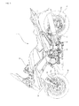
- the motorcycle 1 includes a body frame 10.
- a head pipe (not shown) is formed on a front end portion of the body frame 10.
- a steering shaft (not shown) is rotatably inserted into the head pipe.
- a pair of left and right front forks 14 are mounted on the steering shaft.
- a front wheel 15 is rotatably supported at lower end portions of the pair of left and right front forks 14.
- a steering handle bar 12 is mounted on the head pipe.
- a pivot shaft (not shown) is mounted on a rear end portion of the body frame 10.
- a rear arm 16 is swingably mounted on the pivot shaft.
- a rear wheel 17 is rotatably supported by a rear end portion of the rear arm 16 .
- the rear wheel 17 is driven by an engine 20 which is suspended by the body frame 10.
- the motorcycle 1 is provided with a braking system 30.
- the braking system 30 is for decelerating the motorcycle 1.
- the braking system 30 of the embodiment includes a front wheel-side braking mechanism which applies a brake to the front wheel 15, a rear wheel-side braking mechanism which applies a brake to the rear wheel 17, a front association mechanism, a rear association mechanism, and an ABS mechanism.
- the front association mechanism refers to a mechanism which drives the rear wheel-side braking mechanism when the front wheel-side braking mechanism is operated.
- the rear association mechanism refers to a mechanism which drives the front wheel-side braking mechanism when the rear wheel-side braking mechanism is operated.
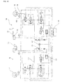
- Most mechanisms of the braking system 30 are accommodated in an HU (Hydraulic Unit) 31.
- the braking system 30 includes a first braking force generating mechanism 35 and a second braking force generating mechanism 36.
- the first braking force generating mechanism 35 is provided to the rear wheel 17.
- the first braking force generating mechanism 35 is supplied with hydraulic pressure, thereby generating a braking force for the rear wheel 17. More specifically, the first braking force generating mechanism 35 includes a first caliper 35a and a first brake disk 35b. The first brake disk 35b rotates together with the rear wheel 17.
- the second braking force generating mechanism 36 is provided to the front wheel 15 ,
- the second braking force generating mechanism 36 is supplied with hydraulic pressure, thereby generating a braking force for the front wheel 15.
- the second braking force generating mechanism 36 includes a second caliper 36a and a second brake disk 36b. More specifically, the second brake disk 36b rotates together with the front wheel 15.
- the first braking force generating mechanism 35 is connected to a first master cylinder 40a through a first brake fluid passage 42.
- a reservoir tank 41a and a brake pedal 18 as a first operation member are connected to the first master cylinder 40a. If a rider operates the brake pedal 18, hydraulic pressure is supplied from the first master cylinder 40a to the first braking force generating mechanism 35.
- the brake pedal 18 is provided with a stroke sensor 18a. An operation amount of the brake pedal 18 is detected also by the stroke sensor 18a. The detected operation amount of the brake pedal 18 is output to a CPU 28a.
- a second hydraulic pressure sensor 43 is connected to a point A of the first brake fluid passage 42.
- the second hydraulic pressure sensor 43 detects hydraulic pressure at the point A of the first brake fluid passage 42.
- a first on-off valve 44 and a third on-off valve 45 are disposed in the first brake fluid passage 42.
- the first on-off valve 44 is disposed between a point B and a point C of the first brake fluid passage 42.
- the first on-off valve 44 is an open-when-nonenergized type on-off valve which opens when electric power is not supplied, and which closes when electric power is supplied.
- the third on-off valve 45 is disposed between the point C and a point D of the first brake fluid passage 42.
- the third on-off valve 45 is also an open-when-nonenergized type on-off valve like the first on-off valve 44.
- a third hydraulic pressure sensor 46 is connected to a point E of the first brake fluid passage 42.
- the third hydraulic pressure sensor 46 can measure hydraulic pressure more precisely than the second hydraulic pressure sensor 43.
- the second hydraulic pressure sensor 43 is more excellent in terms of the resistance to pressure than the third hydraulic pressure sensor 46.
- the point B of the first brake fluid passage 42 closer to the first master cylinder 40a and the point C closer to the side of the first braking force generating mechanism 35 are connected to each other through a third brake fluid passage 47.
- the third brake fluid passage 47 extends from the point B to the point C through a point F and a point H.
- a brake fluid pump 49 is disposed in the third brake fluid passage 47.
- the brake fluid pump 49 is connected to a motor 50.
- the brake fluid pump 49 is activated when the motor 50 is driven by a later-described ECU 28. If the brake fluid pump 49 is activated, pressure on the side of the point B becomes low pressure and the pressure on the side of the point C becomes high pressure.
- a second on-off valve 57 is disposed in the third brake fluid passage 47. More specifically, the second on-off valve 57 is disposed closer to the point B than the brake fluid pump 49 of the third brake fluid passage 47.
- the second on-off valve 57 is a closed-when-nonenergized type on-off valve which closes when electric power is not supplied and which opens when electric power is supplied.
- a buffer chamber 58 is connected to the point H of the third brake fluid passage 47.
- the point F which is located closer to the point B than the second on-off valve 57, is connected to the second caliper 36a through a fourth brake fluid passage 51.
- a fifth on-off valve 52 is disposed between the point F and a point G of the fourth brake fluid passage 51.
- the fifth on-off valve 52 is an open-when-nonenergized type on-off valve.
- a metering valve 53 is disposed between the point G of the fourth brake fluid passage 51 and the second caliper 36a.
- the point D of the first brake fluid passage 42 and the point H of the third brake fluid passage 47 are connected to each other through a fifth brake fluid passage 56.
- a fourth on-off valve 48 is disposed in the fifth brake fluid passage 56.
- the fourth on-off valve 48 is a closed-when-nonenergized type on-off valve.
- the point G of the fourth brake fluid passage 51 and a point I of the fifth brake fluid passage 56 are connected to each other through a sixth brake fluid passage 54.
- a sixth on-off valve 55 is disposed in the sixth brake fluid passage 54.
- the sixth on-off valve 55 is a closed-when-nonenergized type on-off valve.
- the second braking force generating mechanism 36 is connected to a second master cylinder 40b through a second brake fluid passage 60.
- a reservoir tank 41b and a brake lever 13 as a second operation member are connected to the second master cylinder 40b. If a rider operates the brake lever 13, hydraulic pressure is supplied from the second master cylinder 40b to the second braking force generating mechanism 36.
- a stroke sensor 13a is provided to the brake lever 13. The operation amount of the brake lever 13 is detected also by the stroke sensor 13a. The detected operation amount of the brake lever 13 is output to the CPU 28a.
- a first hydraulic pressure sensor 61 as an operation amount detection section is connected to a point J of the second brake fluid passage 60.
- the first hydraulic pressure sensor 61 detects hydraulic pressure at the point J of the second brake fluid passage 60. With this, the operation amount of the brake lever 13 as the second operation member is indirectly detected.
- the first hydraulic pressure sensor 61 detects both hydraulic pressure in the second brake fluid passage 60 and the operation of the brake lever 13. Therefore, as compared with a case where a special-purpose sensor for detecting the operation of the brake lever 13 is provided, the number of parts can be reduced and the structure can be simplified.
- a sensor which directly detects the operation amount of the brake lever 13 may be disposed instead of the first hydraulic pressure sensor 61, or together with the first hydraulic pressure sensor 61.
- An example of the sensor which directly detects the operation amount of the brake lever 13 includes a position sensor which detects a position of the brake lever 13.
- a seventh on-off valve 62 is disposed in a portion closer to the second braking force generating mechanism 36 than the point J of the second brake fluid passage 60.
- the seventh on-off valve 62 is an open-when-nonenergized type on-off valve.
- a point K of the second brake fluid passage 60 closer to the second master cylinder 40b and a point L of the second brake fluid passage 60 closer to the side of the second braking force generating mechanism 36 than the seventh on-off valve 62 are connected to each other through a seventh brake fluid passage 63.
- a second brake fluid pump 64 is disposed in the seventh brake fluid passage 63.
- the second brake fluid pump 64 is driven by the motor 50 mentioned above. If the second brake fluid pump 64 is driven, the pressure on the side of the point L becomes low pressure and the pressure on the side of the point K becomes high pressure.
- the motor 50 in a state where a power source of the motorcycle 1 is ON, the motor 50 is always driven, and the first and the second brake fluid pumps 49 and 64 are always activated.
- An eighth on-off valve 65 is disposed between the second brake fluid pump 64 and the point L.
- the eighth on-off valve 65 is a closed-when-nonenergized type on-off valve.
- a buffer chamber 66 is connected to a connection point between the eighth on-off valve 65 and the second brake fluid pump 64.
- the ECU (Electronic Control Unit) 28 as a control unit is disposed adjacent to the HU 31.
- the ECU 28 is used only for controlling the HU 31.
- An ECU (not shown) used for controlling the engine 20 shown in Fig. 1 is provided independently from the ECU 28.
- the present invention is not limited to this configuration.
- one ECU 28 may control both the engine 20 and the HU 31.
- the ECU 28 includes the CPU 28a as a calculating section and a memory 28b as a storing section connected to the CPU 28a.
- Various settings are stored in the memory 28b as will be described in detail later.
- Various detection values are also stored in the memory 28b.
- the CPU 28a is connected to the on-off valves, the hydraulic pressure sensors and the motor 50 which are included in the HU 31.
- the on-off valves and the motor 50 included in the HU 31 are controlled by the CPU 28a. Hydraulic pressures detected by the hydraulic pressure sensors 43, 46 and 61 are sent to the CPU 28a.
- a front wheel rotation speed sensor 27a and a rear wheel rotation speed sensor 27b are connected to the CPU 28a.
- a rotation speed of the front wheel 15 is detected by the front wheel rotation speed sensor 27a and is output to the CPU 28a.
- a rotation speed of the rear wheel 17 is detected by the rear wheel rotation speed sensor 27b and is output to the CPU 28a.
- the CPU 28a calculates a vehicle speed which is a speed of the motorcycle 1 based on output from the front wheel rotation speed sensor 27a and the rear wheel rotation speed sensor 27b. That is, in this embodiment, the front wheel rotation speed sensor 27a and the rear wheel rotation speed sensor 27b constitute a vehicle speed sensor 27.
- a method for calculating a vehicle speed from the front wheel rotation speed and the rear wheel rotation speed is not especially limited.
- an average value of the front wheel rotation speed and the rear wheel rotation speed may be defined as the vehicle speed.
- Fig. 4 is a schematic structure diagram of the braking system when the brake lever 13 is operated.
- hydraulic pressure is supplied from the second master cylinder 40b.
- the seventh on-off valve 62 is the apen-when-nonenergized type on-off valve. Therefore, hydraulic pressure from the second master cylinder 40b is supplied to the second caliper 36a through the second brake fluid passage 60. With this, a braking force is generated in the second braking force generating mechanism 36 which is provided to the front wheel 15.
- the increase of hydraulic pressure in the second brake fluid passage 60 is detected by the first hydraulic pressure sensor 61, and this fact is output to the ECU 28.
- the ECU 28 determines whether or not the brake lever 13 is operated based on hydraulic pressure in the second brake fluid passage 60.
- the ECU 28 determines that the brake lever 13 is operated, the ECU 28 closes the first on-off valve 44 and opens the second on-off valve 57.
- brake fluid in the first master cylinder 40a is sucked by the first brake fluid pump 49, and the brake fluid is supplied to the first caliper 35a through the third brake fluid passage 47 and the first brake fluid passage 42.
- a braking force is generated in the first braking force generating mechanism 35 which is provided to the rear wheel 17.
- a braking force is generated in the second braking force generating mechanism 36 and a braking force is generated also in the first braking force generating mechanism 35.
- This associationed operation is realized through the ECU 28. For this reason, this front associationed operation is called an electrically associationed operation.
- Fig. 5 is a schematic structure diagram of the braking system when the brake pedal 18 is operated.
- brake fluid is discharged from the first master cylinder 40a.
- the first on-off valve 44 and the third on-off valve 45 are open-when-nonenergized type on-off valves. Therefore, the brake fluid discharged from the first master cylinder 40a is supplied to the first caliper 35a through the first brake fluid passage 42. With this, a braking force is generated in the first braking force generating mechanism 35 which is provided to the rear wheel 17.
- the fifth on-off valve 52 is also the open-when-nonenergized type on-off valve. Therefore, brake fluid discharged from the first master cylinder 40a is supplied also to the second caliper 36a through the fourth brake fluid passage 51. With this, a braking force is generated in the second braking force generating mechanism 36 which is provided to the front wheel 15.
- a braking force is generated not only in the first braking force generating mechanism 35 but also in the second braking force generating mechanism 36.
- This associationed operation is different from the associationed operation caused when the brake lever 13 is operated and is mechanically performed without using the ECU 28.
- this rear associationed operation is called a mechanically associationed operation.
- Fig. 6 is a schematic structure diagram of the braking system for describing the ABS action of the second braking force generating mechanism 36 when the brake lever 13 is operated.
- the ECU 28 detects a locked state of the front wheel 15 based on output from the front wheel rotation speed sensor 27a and output from the rear wheel rotation speed sensor 27b. More specifically, the ECU 28 detects the locked state of the front wheel 15 when the magnitude of the front wheel rotation speed is largely reduced with respect to the vehicle speed.
- the ECU 28 If the ECU 28 detects the locked state of the front wheel 15, the ECU 28 supplies current to the seventh and the eighth on-off valves 62 and 65. With this, the seventh on-off valve 62 is closed and the eighth on-off valve 65 is opened. Therefore, brake fluid is sent from the second caliper 36a to the second master cylinder 40b through the seventh brake fluid passage 63. As a result, a braking force generated in the second braking force generating mechanism 36 is reduced.
- the ECU 28 If the ECU 28 detects that the locked state of the front wheel 15 is released, the ECU 28 stops the current supply to the seventh and the eighth on-off valves 62 and 65. With this, the seventh on-off valve 62 is opened and the eighth on-off valve 65 is closed. As a result, a braking force generated in the second braking force generating mechanism 36 is again increased.
- Fig. 7 is a schematic structure diagram of the braking system for describing the ABS action of the first and the second braking force generating mechanisms 35 and 36 when the brake pedal 18 is operated.
- the ECU 28 detects the locked state of the rear wheel 17 based on output from the front wheel rotation speed sensor 27a and output from the rear wheel rotation speed sensor 27b. More specifically, the ECU 28 detects the locked state of the rear wheel 17 when the level of the rear wheel rotation speed is largely reduced with respect to the vehicle speed.
- the ECU 28 If the ECU 28 detects the locked state of the rear wheel 17, the ECU 28 supplies current to the third on-off valve 45 and the fourth on-off valve 48. With this, the third on-off valve 45 is closed and the fourth on-off valve 48 is opened. Therefore, the brake fluid in the first caliper 35a is sent to the first master cylinder 40a through the third brake fluid passage 47. As a result, a braking force generated in the first braking force generating mechanism 35 is reduced.
- the ECU 28 If the ECU 28 detects that the locked state of the rear wheel 17 is released, the ECU 28 stops the current supply to the third and the fourth on-off valves 45 and 48. With this, the third on-off valve 45 is opened and the fourth on-off valve 48 is closed. As a result, a braking force generated in the first braking force generating mechanism 35 is again increased.
- the ECU 28 If the ECU 28 detects the locked state of the front wheel 15, the ECU 28 supplies current to the fifth on-off valve 52 and the sixth on-off valve 55 as shown in Fig. 7 . With this, the fifth on-off valve 52 is closed and the sixth on-off valve 55 is opened. Thus, brake fluid in the second caliper 36a is sent to the second master cylinder 40b through the sixth brake fluid passage 54. As a result, a braking force generated in the second braking force generating mechanism 36 is reduced.
- the ECU 28 If the ECU 28 detects that the locked state of the front wheel 15 is released, the ECU 28 stops the current supply to the fifth and the sixth on-off valves 52 and 55. With this, the fifth on-off valve 52 is opened and the sixth on-off valve 55 is closed. As a result, a braking force generated in the second braking force generating mechanism 36 is again increased.
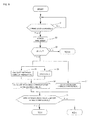
- the ECU 28 first determines in step S1 whether or not the brake lever 13 is being operated. In this embodiment, it is determined whether or not the brake lever 13 is being operated based on hydraulic pressure detected by the first hydraulic pressure sensor 61.
- step S2 is executed.
- the CPU 28a finishes a timer, and causes the memory 28b to store the counted time period (operation interval ( ⁇ t)). This timer was started in later-described step S16 (see Fig. 9 ) when the brake lever 13 was operated previously.
- the operation interval ( ⁇ t) is determined as ⁇ .
- step S3 is executed.
- the CPU 28a determines whether or not the operation interval ( ⁇ t) stored in the memory 28b in step S2 is equal to or less than a predetermined interval t 1 When it is determined in step S3 that ⁇ t ⁇ t 1 the procedure is advanced to step S4 and step S5.
- step S4 and step S5 are simultaneously executed.
- the present invention is not limited to this configuration.
- step S5 may be executed after step S4, or step S5 may be executed before step S4.
- step S4 the CPU 28a calculates a reference hydraulic pressure (P 0 ).
- the reference hydraulic pressure (P 0 ) is calculated in the following manner .
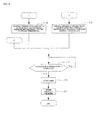
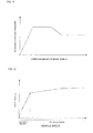
- the memory 28b stores therein a reference hydraulic pressure map, as shown in Fig. 11 , that defines a relation between an operation amount of the brake lever 13 and reference hydraulic pressure.
- the CPU 28a reads the reference hydraulic pressure map from the memory 28b.
- the CPU 28a applies the operation amount of the brake lever 13 calculated from hydraulic pressure detected by the first hydraulic pressure sensor 61 to the reference hydraulic pressure map, thereby calculating the reference hydraulic pressure (P 0 ).
- the reference hydraulic pressure map shown in Fig. 11 is only an example.
- the reference hydraulic pressure map is not limited to that shown in Fig. 11 .
- the reference hydraulic pressure map can appropriately be set in accordance with required characteristics of the motorcycle 1.
- a coefficient ⁇ is calculated by the ECU 28.
- This coefficient ⁇ is suitable for a vehicle speed of the motorcycle 1.
- the memory 28b stores therein a coefficient map, as shown in Fig. 12 , that defines a relation between the coefficient ⁇ and a vehicle speed of the motorcycle 1.
- the CPU 28a reads the coefficient map from the memory 28b.
- the CPU 28a calculates the coefficient ⁇ by applying a vehicle speed when the operation of the brake lever 13 is started to the coefficient map.
- the coefficient map shown in Fig. 12 is only an example.
- the coefficient map is not limited to that shown in Fig. 12 .
- the coefficient map can also be appropriately set in accordance with required characteristics of the motorcycle 1 like the reference hydraulic pressure map.
- a variation amount of the coefficient ⁇ with respect to the variation in vehicle speed is different between in a low speed region where the vehicle speed is relatively low and in a high speed region where the vehicle speed is relatively high. More specifically, the variation amount of the coefficient ⁇ with respect to the variation in vehicle speed in the low speed region is set to be greater than the variation amount of the coefficient ⁇ with respect to the variation in vehicle speed in the high speed region.
- step S6 is executed.
- the CPU 28a calculates a set hydraulic pressure (a first hydraulic pressure) (P 1 )based on the reference hydraulic pressure (P 0 ) and the coefficient ⁇ More specifically, in this embodiment, the CPU 28a calculates the set hydraulic pressure (the first hydraulic pressure) (P 1 by multiplying the reference hydraulic pressure (P 0 ) by the coefficient ⁇
- step S7 is executed in parallel with steps S4 to S6.
- Step S7 may be executed before or after steps S4 to S6.
- step S7 a second hydraulic pressure (P 2 ) is calculated.
- the second hydraulic pressure (P 2 ) is calculated based on the operation interval ( ⁇ t)and hydraulic pressure which had been supplied to the first braking force generating mechanism 35 when the brake lever 13 was operated last time.
- the hydraulic pressure which had been supplied to the first braking force generating mechanism 35 when the brake lever 13 was operated last time is stored in later-described step S17.
- the second hydraulic pressure (P 2 ) is calculated in the following manner.
- a hydraulic pressure reducing amount per predetermined time is stored in the memory 28b.
- the CPU 28a calculates the second hydraulic pressure (P 2) by subtracting a reducing amount obtained by multiplying the hydraulic pressure reducing amount by the operation interval ( ⁇ t) from hydraulic pressure which had been supplied to the first braking force generating mechanism 35 when the brake lever 13 was operated last time. If the brake lever 13 was not operated last time, hydraulic pressure which was supplied to the first braking force generating mechanism 35 when the brake lever 13 was operated last time is set to zero. Thus, the second hydraulic pressure (P 2 )is also calculated as zero.
- Step S8 is executed after steps S6 and S7 are completed.
- the ECU 28 determines whether or not the set hydraulic pressure (the first hydraulic pressure) (P 1 ) is equal to or greater than the second hydraulic pressure (P 2 ). If it is determined in step S8 that the set hydraulic pressure (the first hydraulic pressure) (P 1 ) is equal to or greater than the second hydraulic pressure (P 2 ), the procedure is advanced to step S9 shown in Fig. 9 .
- step S9 the ECU 28 controls the second on-off valve 57 such that hydraulic pressure supplied to the first braking force generating mechanism 35 becomes equal to the set hydraulic pressure (the first hydraulic pressure) (P 1 ). More specifically, the opening of the second on-off valve 57 is adjusted while keeping output of the first brake fluid pump 49 constant, thereby adjusting hydraulic pressure supplied to the first braking force generating mechanism 35.
- the hydraulic pressure supplied to the first braking force generating mechanism 35 in step S9 and later-described step S10 is hydraulic pressure which is detected by the third hydraulic pressure sensor 46.
- the opening of the second on-off valve 57 is adjusted while keeping output of the first brake fluid pump 49 constant, thereby adjusting hydraulic pressure supplied to the first braking force generating mechanism 35 as described above. Therefore, as compared with a case where hydraulic pressure supplied to the first braking force generating mechanism 35 by adjusting output of the first brake fluid pump 49, it is possible to precisely and swiftly adjust hydraulic pressure supplied to the first braking force generating mechanism 35.
- step S8 If it is determined in step S8 that the set hydraulic pressure (the first hydraulic pressure) (P 1 ) is less than the second hydraulic pressure (P 2 ) , the procedure is advanced to step S10.
- step S10 the ECU 28 controls the second on-off valve 57 such that hydraulic pressure supplied to the first braking force generating mechanism 35 becomes equal to the set hydraulic pressure (the second hydraulic pressure) (P 2 ). More specifically, the opening of the second on-off valve 57 is adjusted while keeping output of the first brake fluid pump 49 constant, thereby adjusting hydraulic pressure supplied to the first braking force generating mechanism 35.
- hydraulic pressure supplied to the first braking force generating mechanism 35 is set to one of the set hydraulic pressure (the first hydraulic pressure) (P 1 ) and the second hydraulic pressure (P 2 ), whichever is greater.
- hydraulic pressure supplied to the first braking force generating mechanism 35 is not less than the second hydraulic pressure (P 2 ) obtained by considering the operation interval ( ⁇ t)and hydraulic pressure which was supplied last time to the first braking force generating mechanism 35.
- step S3 If it is determined in step S3 that the operation interval ( ⁇ t) is longer than the predetermined interval t 1, the procedure is advanced to step S11 and step S12 shown in Fig. 10 .
- step S11 and step S12 are executed in parallel.
- the invention is not limited to this configuration.
- step S11 may be executed before or after step S12.
- step S11 the reference hydraulic pressure (P 0 ) is calculated in the same procedure as that of step S4 above.
- step S12 the coefficient ⁇ is calculated in the same procedure as that of step S5 above.
- step S13 is executed.
- the set hydraulic pressure (P 1 ) is calculated in the same procedure as that of step S6 above.
- step S14 the procedure is advanced to step S14.
- step S14 like step S9 above, the ECU 28 controls the second on-off valve 57 such that hydraulic pressure supplied to the first braking force generating mechanism 35 becomes equal to the set hydraulic pressure (the first hydraulic pressure) (P 1 )
- step S15 is executed after steps S9, S10 and S14.
- the ECU 28 determines whether or not the operation of the brake lever 13 is completed based on hydraulic pressure detected by the first hydraulic pressure sensor 61. If it is determined that the operation of the brake lever 13 is not completed, step S15 is again executed.
- step S16 the ECU 28 starts a timer for counting the operation interval ( ⁇ t).
- Step S17 is executed after step S16.
- the CPU 28a causes the memory 28b to store hydraulic pressure supplied to the first braking force generating mechanism at the time 35 when the operation of the brake lever 13 is completed.
- step S17 is executed after step S16 in this embodiment, step S17 may be executed before step S16, or step S17 and step S16 may be executed in parallel.
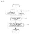
- operation interval counting operation stop control shown in Fig. 13 is also performed by the ECU 28.
- step S21 determines in step S21 whether or not a vehicle speed is increased. If it is determined in step S21 that the vehicle speed is not increased, step S21 is again executed.
- step S21 if it is determined in step S21 that the vehicle speed is increased, the procedure is advanced to step S22.
- step S22 the timer is stopped by the CPU 28a and the counting of the operation interval is terminated.
- the CPU 28a sets the operation interval ( ⁇ t) to zero, and causes the memory 28b to store it.
- steps S4 to S10 are not executed, and hydraulic pressure supplied to the first braking force generating mechanism 35 is always set to the set hydraulic pressure (the first hydraulic pressure) (P 1 )
- throttle opening may be determined. That is, the CPU 28a may determine in step S21 whether or not the Th opening is increased.
- hydraulic pressure supplied to the first braking force generating mechanism 35 with respect to the operation amount of the brake lever 13 is controlled to be increased as the vehicle speed is higher.
- a braking effect that a rider feels when a vehicle speed becomes high is equal to that when a vehicle speed is low. Accordingly, a rider's feeling of incongruity is reduced.
- the first on-off valve 44 is the open-when-nonenergized type on-off valve and the second on-off valve 57 is the closed-when-nanenergized type on-off valve. For this reason, current is supplied to the first and the second on-off valves 44 and 57 only during the time of the front associationed operation, and the rest of the time, current is not supplied. Thus, the consumption amount of battery electric power can be reduced.
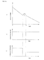
- Fig. 14 is one example of a schematic time chart in which hydraulic pressure supplied to the first braking force generating mechanism 35 during the time of the front associationed operation is differentiated depending upon a vehicle speed when the brake lever 13 is operated but the operation interval (At) is not taken into account.
- Fig. 14(a) shows a vehicle speed.
- Fig. 14(b) shows an operation amount of the brake lever.
- Fig. 14(c) shows hydraulic pressure supplied to the first braking force generating mechanism 35.
- control in which hydraulic pressure supplied to the first braking force generating mechanism 35 during the time of the front associationed operation is differentiated depending upon the vehicle speed when the brake lever 13 is operated but the operation interval ( ⁇ t) is not taken into account is called “control in which operation interval is not taken into account” .
- the vehicle speed when the brake lever 13 is operated is called “initial speed of control”.
Landscapes
- Engineering & Computer Science (AREA)
- Transportation (AREA)
- Mechanical Engineering (AREA)
- Physics & Mathematics (AREA)
- Fluid Mechanics (AREA)
- Regulating Braking Force (AREA)
Priority Applications (1)
| Application Number | Priority Date | Filing Date | Title |
|---|---|---|---|
| EP20090173242 EP2311702B1 (de) | 2009-10-16 | 2009-10-16 | Bremssystem für ein Motorrad |
Applications Claiming Priority (1)
| Application Number | Priority Date | Filing Date | Title |
|---|---|---|---|
| EP20090173242 EP2311702B1 (de) | 2009-10-16 | 2009-10-16 | Bremssystem für ein Motorrad |
Publications (2)
| Publication Number | Publication Date |
|---|---|
| EP2311702A1 true EP2311702A1 (de) | 2011-04-20 |
| EP2311702B1 EP2311702B1 (de) | 2012-12-19 |
Family
ID=41694733
Family Applications (1)
| Application Number | Title | Priority Date | Filing Date |
|---|---|---|---|
| EP20090173242 Active EP2311702B1 (de) | 2009-10-16 | 2009-10-16 | Bremssystem für ein Motorrad |
Country Status (1)
| Country | Link |
|---|---|
| EP (1) | EP2311702B1 (de) |
Cited By (1)
| Publication number | Priority date | Publication date | Assignee | Title |
|---|---|---|---|---|
| CN105775021A (zh) * | 2014-12-22 | 2016-07-20 | 郭美菁 | 时差压力分配输出装置 |
Citations (6)
| Publication number | Priority date | Publication date | Assignee | Title |
|---|---|---|---|---|
| US6409285B1 (en) * | 1999-03-17 | 2002-06-25 | Honda Giken Kogyo Kabushiki Kaisha | Front wheel and rear wheel interlocking brake system for motorcycle |
| EP1277635A2 (de) * | 2001-07-19 | 2003-01-22 | BOSCH BRAKING SYSTEMS Co., Ltd. | Bremssteuerverfahren und Vorrichtung für Motorräder |
| JP2006312372A (ja) | 2005-05-09 | 2006-11-16 | Nissin Kogyo Co Ltd | 車両用ブレーキ制御装置 |
| WO2007118760A1 (de) * | 2006-04-11 | 2007-10-25 | Continental Teves Ag & Co. Ohg | Verfahren zur regelung des druckes in einem elektronisch gesteuerten bremssystem und elektronisches bremssystem |
| WO2008090783A1 (ja) * | 2007-01-26 | 2008-07-31 | Bosch Corporation | 自動二輪車のブレーキ制御装置 |
| EP1964738A2 (de) * | 2007-02-27 | 2008-09-03 | Nissin Kogyo Co., Ltd. | Vorrichtung zur Steuerung des hydraulischen Bremsdruckes für ein Fahrzeug mit Lenker |
-
2009
- 2009-10-16 EP EP20090173242 patent/EP2311702B1/de active Active
Patent Citations (7)
| Publication number | Priority date | Publication date | Assignee | Title |
|---|---|---|---|---|
| US6409285B1 (en) * | 1999-03-17 | 2002-06-25 | Honda Giken Kogyo Kabushiki Kaisha | Front wheel and rear wheel interlocking brake system for motorcycle |
| EP1277635A2 (de) * | 2001-07-19 | 2003-01-22 | BOSCH BRAKING SYSTEMS Co., Ltd. | Bremssteuerverfahren und Vorrichtung für Motorräder |
| JP2006312372A (ja) | 2005-05-09 | 2006-11-16 | Nissin Kogyo Co Ltd | 車両用ブレーキ制御装置 |
| WO2007118760A1 (de) * | 2006-04-11 | 2007-10-25 | Continental Teves Ag & Co. Ohg | Verfahren zur regelung des druckes in einem elektronisch gesteuerten bremssystem und elektronisches bremssystem |
| WO2008090783A1 (ja) * | 2007-01-26 | 2008-07-31 | Bosch Corporation | 自動二輪車のブレーキ制御装置 |
| EP2116436A1 (de) * | 2007-01-26 | 2009-11-11 | Bosch Corporation | Bremssteuerungsvorrichtung für ein zweirädriges motorfahrzeug |
| EP1964738A2 (de) * | 2007-02-27 | 2008-09-03 | Nissin Kogyo Co., Ltd. | Vorrichtung zur Steuerung des hydraulischen Bremsdruckes für ein Fahrzeug mit Lenker |
Cited By (1)
| Publication number | Priority date | Publication date | Assignee | Title |
|---|---|---|---|---|
| CN105775021A (zh) * | 2014-12-22 | 2016-07-20 | 郭美菁 | 时差压力分配输出装置 |
Also Published As
| Publication number | Publication date |
|---|---|
| EP2311702B1 (de) | 2012-12-19 |
Similar Documents
| Publication | Publication Date | Title |
|---|---|---|
| US20160114775A1 (en) | Vehicle brake device | |
| JP6692313B2 (ja) | バーハンドル車両用ブレーキ制御装置 | |
| US8150590B2 (en) | Two-wheeled motor vehicle brake control method and system | |
| EP2311704B1 (de) | Bremssystem für ein Motorrad | |
| JP6606114B2 (ja) | バーハンドル車両用ブレーキ制御装置 | |
| US20070278853A1 (en) | Motorcycle Brake System | |
| CN114007935A (zh) | 控制装置及控制方法 | |
| CN107406062B (zh) | 液压装置以及液压装置的控制方法 | |
| EP2311702B1 (de) | Bremssystem für ein Motorrad | |
| EP2075169A2 (de) | Bremsvorrichtung und damit versehenes Grätschsitz-Fahrzeug | |
| EP2647534B1 (de) | Bremssystem für ein Motorrad | |
| KR102525956B1 (ko) | 전자식 브레이크 시스템 및 그 제어방법 | |
| EP2311699B1 (de) | Bremssystem für ein Motorrad | |
| EP2311701A1 (de) | Bremssystem für ein Motorrad | |
| EP2586669B1 (de) | Bremssystem für ein Motorrad | |
| US20090115243A1 (en) | Method for Regulating The Pressure In An Electronically Controlled Brake System, and Electronic Brake System | |
| US20210162964A1 (en) | Controller and control method | |
| JP4790744B2 (ja) | 車両用ブレーキ液圧制御装置 | |
| JP4705498B2 (ja) | 車両の急ブレーキ判断装置 | |
| EP2311703B1 (de) | Bremssystem für ein Motorrad | |
| JP6281878B2 (ja) | 車両用ブレーキ液圧制御装置 | |
| JP2021112988A (ja) | バーハンドル車両用ブレーキ液圧制御装置 | |
| US8186769B2 (en) | Two-wheeled motor vehicle brake control method and system | |
| JP4432237B2 (ja) | 車両用制動制御装置 | |
| JP4258273B2 (ja) | 車両用制動システム |
Legal Events
| Date | Code | Title | Description |
|---|---|---|---|
| PUAI | Public reference made under article 153(3) epc to a published international application that has entered the european phase |
Free format text: ORIGINAL CODE: 0009012 |
|
| AK | Designated contracting states |
Kind code of ref document: A1 Designated state(s): AT BE BG CH CY CZ DE DK EE ES FI FR GB GR HR HU IE IS IT LI LT LU LV MC MK MT NL NO PL PT RO SE SI SK SM TR |
|
| AX | Request for extension of the european patent |
Extension state: AL BA RS |
|
| 17P | Request for examination filed |
Effective date: 20111005 |
|
| RIC1 | Information provided on ipc code assigned before grant |
Ipc: B62L 3/08 20060101ALN20120328BHEP Ipc: B60T 8/26 20060101AFI20120328BHEP Ipc: B60T 8/40 20060101ALI20120328BHEP |
|
| RIN1 | Information on inventor provided before grant (corrected) |
Inventor name: WATANABE, TAKAHIRO C/O YAMAHA HATSUDOKI KABUSHIKI Inventor name: UCHIDA, TAKANORI C/O CONTINENTAL AUTOMOTIVE CORPOR Inventor name: MEIXNER, MICHAEL Inventor name: KUSANO, TAISHI C/O CONTINENTAL AUTOMOTIVE CORPORAT Inventor name: KAJIWARA, KUNIO C/O YAMAHA HATSUDOKI KABUSHIKI KAI Inventor name: KREMER, MICHAEL |
|
| GRAP | Despatch of communication of intention to grant a patent |
Free format text: ORIGINAL CODE: EPIDOSNIGR1 |
|
| RAP1 | Party data changed (applicant data changed or rights of an application transferred) |
Owner name: YAMAHA HATSUDOKI KABUSHIKI KAISHA Owner name: CONTINENTAL TEVES AG & CO. OHG Owner name: CONTINENTAL AUTOMOTIVE CORPORATION |
|
| GRAS | Grant fee paid |
Free format text: ORIGINAL CODE: EPIDOSNIGR3 |
|
| GRAA | (expected) grant |
Free format text: ORIGINAL CODE: 0009210 |
|
| AK | Designated contracting states |
Kind code of ref document: B1 Designated state(s): AT BE BG CH CY CZ DE DK EE ES FI FR GB GR HR HU IE IS IT LI LT LU LV MC MK MT NL NO PL PT RO SE SI SK SM TR |
|
| REG | Reference to a national code |
Ref country code: GB Ref legal event code: FG4D |
|
| REG | Reference to a national code |
Ref country code: CH Ref legal event code: EP |
|
| REG | Reference to a national code |
Ref country code: AT Ref legal event code: REF Ref document number: 589219 Country of ref document: AT Kind code of ref document: T Effective date: 20130115 |
|
| REG | Reference to a national code |
Ref country code: DE Ref legal event code: R096 Ref document number: 602009012013 Country of ref document: DE Effective date: 20130228 |
|
| PG25 | Lapsed in a contracting state [announced via postgrant information from national office to epo] |
Ref country code: ES Free format text: LAPSE BECAUSE OF FAILURE TO SUBMIT A TRANSLATION OF THE DESCRIPTION OR TO PAY THE FEE WITHIN THE PRESCRIBED TIME-LIMIT Effective date: 20130330 Ref country code: FI Free format text: LAPSE BECAUSE OF FAILURE TO SUBMIT A TRANSLATION OF THE DESCRIPTION OR TO PAY THE FEE WITHIN THE PRESCRIBED TIME-LIMIT Effective date: 20121219 Ref country code: SE Free format text: LAPSE BECAUSE OF FAILURE TO SUBMIT A TRANSLATION OF THE DESCRIPTION OR TO PAY THE FEE WITHIN THE PRESCRIBED TIME-LIMIT Effective date: 20121219 Ref country code: HR Free format text: LAPSE BECAUSE OF FAILURE TO SUBMIT A TRANSLATION OF THE DESCRIPTION OR TO PAY THE FEE WITHIN THE PRESCRIBED TIME-LIMIT Effective date: 20121219 Ref country code: LT Free format text: LAPSE BECAUSE OF FAILURE TO SUBMIT A TRANSLATION OF THE DESCRIPTION OR TO PAY THE FEE WITHIN THE PRESCRIBED TIME-LIMIT Effective date: 20121219 Ref country code: NO Free format text: LAPSE BECAUSE OF FAILURE TO SUBMIT A TRANSLATION OF THE DESCRIPTION OR TO PAY THE FEE WITHIN THE PRESCRIBED TIME-LIMIT Effective date: 20130319 |
|
| REG | Reference to a national code |
Ref country code: NL Ref legal event code: VDEP Effective date: 20121219 Ref country code: AT Ref legal event code: MK05 Ref document number: 589219 Country of ref document: AT Kind code of ref document: T Effective date: 20121219 |
|
| REG | Reference to a national code |
Ref country code: LT Ref legal event code: MG4D |
|
| PG25 | Lapsed in a contracting state [announced via postgrant information from national office to epo] |
Ref country code: GR Free format text: LAPSE BECAUSE OF FAILURE TO SUBMIT A TRANSLATION OF THE DESCRIPTION OR TO PAY THE FEE WITHIN THE PRESCRIBED TIME-LIMIT Effective date: 20130320 Ref country code: SI Free format text: LAPSE BECAUSE OF FAILURE TO SUBMIT A TRANSLATION OF THE DESCRIPTION OR TO PAY THE FEE WITHIN THE PRESCRIBED TIME-LIMIT Effective date: 20121219 Ref country code: LV Free format text: LAPSE BECAUSE OF FAILURE TO SUBMIT A TRANSLATION OF THE DESCRIPTION OR TO PAY THE FEE WITHIN THE PRESCRIBED TIME-LIMIT Effective date: 20121219 |
|
| PG25 | Lapsed in a contracting state [announced via postgrant information from national office to epo] |
Ref country code: BE Free format text: LAPSE BECAUSE OF FAILURE TO SUBMIT A TRANSLATION OF THE DESCRIPTION OR TO PAY THE FEE WITHIN THE PRESCRIBED TIME-LIMIT Effective date: 20121219 Ref country code: BG Free format text: LAPSE BECAUSE OF FAILURE TO SUBMIT A TRANSLATION OF THE DESCRIPTION OR TO PAY THE FEE WITHIN THE PRESCRIBED TIME-LIMIT Effective date: 20130319 Ref country code: EE Free format text: LAPSE BECAUSE OF FAILURE TO SUBMIT A TRANSLATION OF THE DESCRIPTION OR TO PAY THE FEE WITHIN THE PRESCRIBED TIME-LIMIT Effective date: 20121219 Ref country code: IS Free format text: LAPSE BECAUSE OF FAILURE TO SUBMIT A TRANSLATION OF THE DESCRIPTION OR TO PAY THE FEE WITHIN THE PRESCRIBED TIME-LIMIT Effective date: 20130419 Ref country code: AT Free format text: LAPSE BECAUSE OF FAILURE TO SUBMIT A TRANSLATION OF THE DESCRIPTION OR TO PAY THE FEE WITHIN THE PRESCRIBED TIME-LIMIT Effective date: 20121219 Ref country code: CZ Free format text: LAPSE BECAUSE OF FAILURE TO SUBMIT A TRANSLATION OF THE DESCRIPTION OR TO PAY THE FEE WITHIN THE PRESCRIBED TIME-LIMIT Effective date: 20121219 Ref country code: SK Free format text: LAPSE BECAUSE OF FAILURE TO SUBMIT A TRANSLATION OF THE DESCRIPTION OR TO PAY THE FEE WITHIN THE PRESCRIBED TIME-LIMIT Effective date: 20121219 |
|
| PG25 | Lapsed in a contracting state [announced via postgrant information from national office to epo] |
Ref country code: RO Free format text: LAPSE BECAUSE OF FAILURE TO SUBMIT A TRANSLATION OF THE DESCRIPTION OR TO PAY THE FEE WITHIN THE PRESCRIBED TIME-LIMIT Effective date: 20121219 Ref country code: NL Free format text: LAPSE BECAUSE OF FAILURE TO SUBMIT A TRANSLATION OF THE DESCRIPTION OR TO PAY THE FEE WITHIN THE PRESCRIBED TIME-LIMIT Effective date: 20121219 Ref country code: PT Free format text: LAPSE BECAUSE OF FAILURE TO SUBMIT A TRANSLATION OF THE DESCRIPTION OR TO PAY THE FEE WITHIN THE PRESCRIBED TIME-LIMIT Effective date: 20130419 Ref country code: PL Free format text: LAPSE BECAUSE OF FAILURE TO SUBMIT A TRANSLATION OF THE DESCRIPTION OR TO PAY THE FEE WITHIN THE PRESCRIBED TIME-LIMIT Effective date: 20121219 |
|
| PLBE | No opposition filed within time limit |
Free format text: ORIGINAL CODE: 0009261 |
|
| STAA | Information on the status of an ep patent application or granted ep patent |
Free format text: STATUS: NO OPPOSITION FILED WITHIN TIME LIMIT |
|
| PG25 | Lapsed in a contracting state [announced via postgrant information from national office to epo] |
Ref country code: DK Free format text: LAPSE BECAUSE OF FAILURE TO SUBMIT A TRANSLATION OF THE DESCRIPTION OR TO PAY THE FEE WITHIN THE PRESCRIBED TIME-LIMIT Effective date: 20121219 |
|
| 26N | No opposition filed |
Effective date: 20130920 |
|
| PG25 | Lapsed in a contracting state [announced via postgrant information from national office to epo] |
Ref country code: CY Free format text: LAPSE BECAUSE OF FAILURE TO SUBMIT A TRANSLATION OF THE DESCRIPTION OR TO PAY THE FEE WITHIN THE PRESCRIBED TIME-LIMIT Effective date: 20121219 |
|
| PG25 | Lapsed in a contracting state [announced via postgrant information from national office to epo] |
Ref country code: IT Free format text: LAPSE BECAUSE OF FAILURE TO SUBMIT A TRANSLATION OF THE DESCRIPTION OR TO PAY THE FEE WITHIN THE PRESCRIBED TIME-LIMIT Effective date: 20121219 |
|
| REG | Reference to a national code |
Ref country code: DE Ref legal event code: R097 Ref document number: 602009012013 Country of ref document: DE Effective date: 20130920 |
|
| PG25 | Lapsed in a contracting state [announced via postgrant information from national office to epo] |
Ref country code: MC Free format text: LAPSE BECAUSE OF FAILURE TO SUBMIT A TRANSLATION OF THE DESCRIPTION OR TO PAY THE FEE WITHIN THE PRESCRIBED TIME-LIMIT Effective date: 20121219 |
|
| REG | Reference to a national code |
Ref country code: CH Ref legal event code: PL |
|
| GBPC | Gb: european patent ceased through non-payment of renewal fee |
Effective date: 20131016 |
|
| REG | Reference to a national code |
Ref country code: IE Ref legal event code: MM4A |
|
| PG25 | Lapsed in a contracting state [announced via postgrant information from national office to epo] |
Ref country code: GB Free format text: LAPSE BECAUSE OF NON-PAYMENT OF DUE FEES Effective date: 20131016 Ref country code: CH Free format text: LAPSE BECAUSE OF NON-PAYMENT OF DUE FEES Effective date: 20131031 Ref country code: LI Free format text: LAPSE BECAUSE OF NON-PAYMENT OF DUE FEES Effective date: 20131031 |
|
| PG25 | Lapsed in a contracting state [announced via postgrant information from national office to epo] |
Ref country code: IE Free format text: LAPSE BECAUSE OF NON-PAYMENT OF DUE FEES Effective date: 20131016 |
|
| PG25 | Lapsed in a contracting state [announced via postgrant information from national office to epo] |
Ref country code: SM Free format text: LAPSE BECAUSE OF FAILURE TO SUBMIT A TRANSLATION OF THE DESCRIPTION OR TO PAY THE FEE WITHIN THE PRESCRIBED TIME-LIMIT Effective date: 20121219 |
|
| PG25 | Lapsed in a contracting state [announced via postgrant information from national office to epo] |
Ref country code: TR Free format text: LAPSE BECAUSE OF FAILURE TO SUBMIT A TRANSLATION OF THE DESCRIPTION OR TO PAY THE FEE WITHIN THE PRESCRIBED TIME-LIMIT Effective date: 20121219 |
|
| PG25 | Lapsed in a contracting state [announced via postgrant information from national office to epo] |
Ref country code: HU Free format text: LAPSE BECAUSE OF FAILURE TO SUBMIT A TRANSLATION OF THE DESCRIPTION OR TO PAY THE FEE WITHIN THE PRESCRIBED TIME-LIMIT; INVALID AB INITIO Effective date: 20091016 Ref country code: MK Free format text: LAPSE BECAUSE OF FAILURE TO SUBMIT A TRANSLATION OF THE DESCRIPTION OR TO PAY THE FEE WITHIN THE PRESCRIBED TIME-LIMIT Effective date: 20121219 Ref country code: LU Free format text: LAPSE BECAUSE OF NON-PAYMENT OF DUE FEES Effective date: 20131016 |
|
| PG25 | Lapsed in a contracting state [announced via postgrant information from national office to epo] |
Ref country code: MT Free format text: LAPSE BECAUSE OF FAILURE TO SUBMIT A TRANSLATION OF THE DESCRIPTION OR TO PAY THE FEE WITHIN THE PRESCRIBED TIME-LIMIT Effective date: 20121219 |
|
| REG | Reference to a national code |
Ref country code: FR Ref legal event code: PLFP Year of fee payment: 7 |
|
| REG | Reference to a national code |
Ref country code: FR Ref legal event code: PLFP Year of fee payment: 8 |
|
| REG | Reference to a national code |
Ref country code: FR Ref legal event code: PLFP Year of fee payment: 9 |
|
| REG | Reference to a national code |
Ref country code: FR Ref legal event code: PLFP Year of fee payment: 10 |
|
| REG | Reference to a national code |
Ref country code: DE Ref legal event code: R081 Ref document number: 602009012013 Country of ref document: DE Owner name: YAMAHA HATSUDOKI KABUSHIKI KAISHA, IWATA, JP Free format text: FORMER OWNERS: CONTINENTAL AUTOMOTIVE CORP., YOKOHAMA, KANAGAWA, JP; CONTINENTAL TEVES AG & CO. OHG, 60488 FRANKFURT, DE; YAMAHA HATSUDOKI KABUSHIKI KAISHA, IWATA, SHIZUOKA, JP Ref country code: DE Ref legal event code: R081 Ref document number: 602009012013 Country of ref document: DE Owner name: CONTINENTAL AUTOMOTIVE TECHNOLOGIES GMBH, DE Free format text: FORMER OWNERS: CONTINENTAL AUTOMOTIVE CORP., YOKOHAMA, KANAGAWA, JP; CONTINENTAL TEVES AG & CO. OHG, 60488 FRANKFURT, DE; YAMAHA HATSUDOKI KABUSHIKI KAISHA, IWATA, SHIZUOKA, JP Ref country code: DE Ref legal event code: R081 Ref document number: 602009012013 Country of ref document: DE Owner name: CONTINENTAL AUTOMOTIVE CORP., YOKOHAMA, JP Free format text: FORMER OWNERS: CONTINENTAL AUTOMOTIVE CORP., YOKOHAMA, KANAGAWA, JP; CONTINENTAL TEVES AG & CO. OHG, 60488 FRANKFURT, DE; YAMAHA HATSUDOKI KABUSHIKI KAISHA, IWATA, SHIZUOKA, JP |
|
| P01 | Opt-out of the competence of the unified patent court (upc) registered |
Effective date: 20230626 |
|
| PGFP | Annual fee paid to national office [announced via postgrant information from national office to epo] |
Ref country code: FR Payment date: 20231024 Year of fee payment: 15 Ref country code: DE Payment date: 20231026 Year of fee payment: 15 |
|
| REG | Reference to a national code |
Ref country code: DE Ref legal event code: R081 Ref document number: 602009012013 Country of ref document: DE Owner name: YAMAHA HATSUDOKI KABUSHIKI KAISHA, IWATA, JP Free format text: FORMER OWNERS: CONTINENTAL AUTOMOTIVE CORP., YOKOHAMA, KANAGAWA, JP; CONTINENTAL AUTOMOTIVE TECHNOLOGIES GMBH, 30165 HANNOVER, DE; YAMAHA HATSUDOKI KABUSHIKI KAISHA, IWATA, SHIZUOKA, JP Ref country code: DE Ref legal event code: R081 Ref document number: 602009012013 Country of ref document: DE Owner name: CONTINENTAL AUTOMOTIVE TECHNOLOGIES GMBH, DE Free format text: FORMER OWNERS: CONTINENTAL AUTOMOTIVE CORP., YOKOHAMA, KANAGAWA, JP; CONTINENTAL AUTOMOTIVE TECHNOLOGIES GMBH, 30165 HANNOVER, DE; YAMAHA HATSUDOKI KABUSHIKI KAISHA, IWATA, SHIZUOKA, JP Ref country code: DE Ref legal event code: R081 Ref document number: 602009012013 Country of ref document: DE Owner name: CONTINENTAL AUTOMOTIVE CORP., YOKOHAMA, JP Free format text: FORMER OWNERS: CONTINENTAL AUTOMOTIVE CORP., YOKOHAMA, KANAGAWA, JP; CONTINENTAL AUTOMOTIVE TECHNOLOGIES GMBH, 30165 HANNOVER, DE; YAMAHA HATSUDOKI KABUSHIKI KAISHA, IWATA, SHIZUOKA, JP |