EP2309961B1 - Wound dressing of continuous fibers - Google Patents
Wound dressing of continuous fibers Download PDFInfo
- Publication number
- EP2309961B1 EP2309961B1 EP09805589.0A EP09805589A EP2309961B1 EP 2309961 B1 EP2309961 B1 EP 2309961B1 EP 09805589 A EP09805589 A EP 09805589A EP 2309961 B1 EP2309961 B1 EP 2309961B1
- Authority
- EP
- European Patent Office
- Prior art keywords
- wound
- fibers
- fiber
- sheath
- filler
- Prior art date
- Legal status (The legal status is an assumption and is not a legal conclusion. Google has not performed a legal analysis and makes no representation as to the accuracy of the status listed.)
- Active
Links
- 239000000835 fiber Substances 0.000 title claims description 255
- 239000000463 material Substances 0.000 claims description 115
- 239000000945 filler Substances 0.000 claims description 90
- 239000011159 matrix material Substances 0.000 claims description 52
- 239000012530 fluid Substances 0.000 claims description 48
- 230000002745 absorbent Effects 0.000 claims description 26
- 239000002250 absorbent Substances 0.000 claims description 26
- 230000035876 healing Effects 0.000 claims description 16
- 239000000654 additive Substances 0.000 claims description 13
- 238000004891 communication Methods 0.000 claims description 9
- 230000000996 additive effect Effects 0.000 claims description 8
- 238000002560 therapeutic procedure Methods 0.000 claims description 7
- 206010052428 Wound Diseases 0.000 description 338
- 208000027418 Wounds and injury Diseases 0.000 description 338
- 238000012856 packing Methods 0.000 description 78
- 238000000034 method Methods 0.000 description 71
- 210000000416 exudates and transudate Anatomy 0.000 description 41
- 229920000642 polymer Polymers 0.000 description 36
- -1 polypropylene Polymers 0.000 description 32
- 238000002788 crimping Methods 0.000 description 27
- 239000003795 chemical substances by application Substances 0.000 description 23
- 238000000926 separation method Methods 0.000 description 23
- 230000008569 process Effects 0.000 description 19
- VAZJLPXFVQHDFB-UHFFFAOYSA-N 1-(diaminomethylidene)-2-hexylguanidine Polymers CCCCCCN=C(N)N=C(N)N VAZJLPXFVQHDFB-UHFFFAOYSA-N 0.000 description 17
- 239000004743 Polypropylene Substances 0.000 description 17
- 229920001155 polypropylene Polymers 0.000 description 17
- 229920002413 Polyhexanide Polymers 0.000 description 15
- 239000006260 foam Substances 0.000 description 14
- 229920002994 synthetic fiber Polymers 0.000 description 13
- 239000004599 antimicrobial Substances 0.000 description 12
- 230000001070 adhesive effect Effects 0.000 description 11
- 239000004698 Polyethylene Substances 0.000 description 10
- 239000000853 adhesive Substances 0.000 description 10
- 229920000573 polyethylene Polymers 0.000 description 10
- 239000012209 synthetic fiber Substances 0.000 description 10
- 238000007373 indentation Methods 0.000 description 9
- GHXZTYHSJHQHIJ-UHFFFAOYSA-N Chlorhexidine Chemical compound C=1C=C(Cl)C=CC=1NC(N)=NC(N)=NCCCCCCN=C(N)N=C(N)NC1=CC=C(Cl)C=C1 GHXZTYHSJHQHIJ-UHFFFAOYSA-N 0.000 description 8
- 238000007789 sealing Methods 0.000 description 8
- 238000011282 treatment Methods 0.000 description 8
- KCXVZYZYPLLWCC-UHFFFAOYSA-N EDTA Chemical compound OC(=O)CN(CC(O)=O)CCN(CC(O)=O)CC(O)=O KCXVZYZYPLLWCC-UHFFFAOYSA-N 0.000 description 7
- 230000000845 anti-microbial effect Effects 0.000 description 7
- 238000004519 manufacturing process Methods 0.000 description 7
- 229920000098 polyolefin Polymers 0.000 description 7
- 229920000742 Cotton Polymers 0.000 description 6
- MUBZPKHOEPUJKR-UHFFFAOYSA-N Oxalic acid Chemical compound OC(=O)C(O)=O MUBZPKHOEPUJKR-UHFFFAOYSA-N 0.000 description 6
- 229920001131 Pulp (paper) Polymers 0.000 description 6
- 230000015572 biosynthetic process Effects 0.000 description 6
- 230000001747 exhibiting effect Effects 0.000 description 6
- 238000005755 formation reaction Methods 0.000 description 6
- 239000012528 membrane Substances 0.000 description 6
- 229920000297 Rayon Polymers 0.000 description 5
- 230000004888 barrier function Effects 0.000 description 5
- 229960003260 chlorhexidine Drugs 0.000 description 5
- 238000009581 negative-pressure wound therapy Methods 0.000 description 5
- 239000002964 rayon Substances 0.000 description 5
- ULGZDMOVFRHVEP-RWJQBGPGSA-N Erythromycin Chemical compound O([C@@H]1[C@@H](C)C(=O)O[C@@H]([C@@]([C@H](O)[C@@H](C)C(=O)[C@H](C)C[C@@](C)(O)[C@H](O[C@H]2[C@@H]([C@H](C[C@@H](C)O2)N(C)C)O)[C@H]1C)(C)O)CC)[C@H]1C[C@@](C)(OC)[C@@H](O)[C@H](C)O1 ULGZDMOVFRHVEP-RWJQBGPGSA-N 0.000 description 4
- XEEYBQQBJWHFJM-UHFFFAOYSA-N Iron Chemical compound [Fe] XEEYBQQBJWHFJM-UHFFFAOYSA-N 0.000 description 4
- 241001465754 Metazoa Species 0.000 description 4
- 239000004677 Nylon Substances 0.000 description 4
- 239000004372 Polyvinyl alcohol Substances 0.000 description 4
- 239000002253 acid Substances 0.000 description 4
- 229920002678 cellulose Polymers 0.000 description 4
- 239000001913 cellulose Substances 0.000 description 4
- MYSWGUAQZAJSOK-UHFFFAOYSA-N ciprofloxacin Chemical compound C12=CC(N3CCNCC3)=C(F)C=C2C(=O)C(C(=O)O)=CN1C1CC1 MYSWGUAQZAJSOK-UHFFFAOYSA-N 0.000 description 4
- 229920001577 copolymer Polymers 0.000 description 4
- 239000006185 dispersion Substances 0.000 description 4
- 239000003814 drug Substances 0.000 description 4
- SLGWESQGEUXWJQ-UHFFFAOYSA-N formaldehyde;phenol Chemical compound O=C.OC1=CC=CC=C1 SLGWESQGEUXWJQ-UHFFFAOYSA-N 0.000 description 4
- 229910052500 inorganic mineral Inorganic materials 0.000 description 4
- 229920005610 lignin Polymers 0.000 description 4
- 230000007246 mechanism Effects 0.000 description 4
- 230000000813 microbial effect Effects 0.000 description 4
- 239000011707 mineral Substances 0.000 description 4
- 229920001778 nylon Polymers 0.000 description 4
- 229920001568 phenolic resin Polymers 0.000 description 4
- 229920000728 polyester Polymers 0.000 description 4
- 229920002451 polyvinyl alcohol Polymers 0.000 description 4
- XLYOFNOQVPJJNP-UHFFFAOYSA-N water Substances O XLYOFNOQVPJJNP-UHFFFAOYSA-N 0.000 description 4
- RXGSAYBOEDPICZ-UHFFFAOYSA-N 2-[6-[[amino-(diaminomethylideneamino)methylidene]amino]hexyl]-1-(diaminomethylidene)guanidine Chemical compound NC(N)=NC(N)=NCCCCCCN=C(N)N=C(N)N RXGSAYBOEDPICZ-UHFFFAOYSA-N 0.000 description 3
- 229920001410 Microfiber Polymers 0.000 description 3
- 239000004952 Polyamide Substances 0.000 description 3
- 230000001464 adherent effect Effects 0.000 description 3
- 238000013019 agitation Methods 0.000 description 3
- 230000007423 decrease Effects 0.000 description 3
- 238000001125 extrusion Methods 0.000 description 3
- 230000036074 healthy skin Effects 0.000 description 3
- 208000015181 infectious disease Diseases 0.000 description 3
- 238000002844 melting Methods 0.000 description 3
- 230000008018 melting Effects 0.000 description 3
- 239000003658 microfiber Substances 0.000 description 3
- 239000000203 mixture Substances 0.000 description 3
- 229920002647 polyamide Polymers 0.000 description 3
- 239000004814 polyurethane Substances 0.000 description 3
- 229920002635 polyurethane Polymers 0.000 description 3
- 239000004800 polyvinyl chloride Substances 0.000 description 3
- 238000012545 processing Methods 0.000 description 3
- 230000002040 relaxant effect Effects 0.000 description 3
- VYPSYNLAJGMNEJ-UHFFFAOYSA-N silicon dioxide Inorganic materials O=[Si]=O VYPSYNLAJGMNEJ-UHFFFAOYSA-N 0.000 description 3
- 239000000126 substance Substances 0.000 description 3
- 239000011800 void material Substances 0.000 description 3
- 239000003357 wound healing promoting agent Substances 0.000 description 3
- MINDHVHHQZYEEK-UHFFFAOYSA-N (E)-(2S,3R,4R,5S)-5-[(2S,3S,4S,5S)-2,3-epoxy-5-hydroxy-4-methylhexyl]tetrahydro-3,4-dihydroxy-(beta)-methyl-2H-pyran-2-crotonic acid ester with 9-hydroxynonanoic acid Natural products CC(O)C(C)C1OC1CC1C(O)C(O)C(CC(C)=CC(=O)OCCCCCCCCC(O)=O)OC1 MINDHVHHQZYEEK-UHFFFAOYSA-N 0.000 description 2
- 244000198134 Agave sisalana Species 0.000 description 2
- 108010001478 Bacitracin Proteins 0.000 description 2
- XNCOSPRUTUOJCJ-UHFFFAOYSA-N Biguanide Chemical compound NC(N)=NC(N)=N XNCOSPRUTUOJCJ-UHFFFAOYSA-N 0.000 description 2
- 229940123208 Biguanide Drugs 0.000 description 2
- 240000008564 Boehmeria nivea Species 0.000 description 2
- 244000025254 Cannabis sativa Species 0.000 description 2
- 235000012766 Cannabis sativa ssp. sativa var. sativa Nutrition 0.000 description 2
- 235000012765 Cannabis sativa ssp. sativa var. spontanea Nutrition 0.000 description 2
- 229930186147 Cephalosporin Natural products 0.000 description 2
- 229920001661 Chitosan Polymers 0.000 description 2
- 240000000491 Corchorus aestuans Species 0.000 description 2
- 235000011777 Corchorus aestuans Nutrition 0.000 description 2
- 235000010862 Corchorus capsularis Nutrition 0.000 description 2
- 102000000541 Defensins Human genes 0.000 description 2
- 108010002069 Defensins Proteins 0.000 description 2
- 239000003109 Disodium ethylene diamine tetraacetate Substances 0.000 description 2
- 241000196324 Embryophyta Species 0.000 description 2
- IECPWNUMDGFDKC-UHFFFAOYSA-N Fusicsaeure Natural products C12C(O)CC3C(=C(CCC=C(C)C)C(O)=O)C(OC(C)=O)CC3(C)C1(C)CCC1C2(C)CCC(O)C1C IECPWNUMDGFDKC-UHFFFAOYSA-N 0.000 description 2
- 241000219146 Gossypium Species 0.000 description 2
- VEXZGXHMUGYJMC-UHFFFAOYSA-N Hydrochloric acid Chemical compound Cl VEXZGXHMUGYJMC-UHFFFAOYSA-N 0.000 description 2
- 241000500881 Lepisma Species 0.000 description 2
- OJMMVQQUTAEWLP-UHFFFAOYSA-N Lincomycin Natural products CN1CC(CCC)CC1C(=O)NC(C(C)O)C1C(O)C(O)C(O)C(SC)O1 OJMMVQQUTAEWLP-UHFFFAOYSA-N 0.000 description 2
- 240000006240 Linum usitatissimum Species 0.000 description 2
- 235000004431 Linum usitatissimum Nutrition 0.000 description 2
- TYMRLRRVMHJFTF-UHFFFAOYSA-N Mafenide Chemical compound NCC1=CC=C(S(N)(=O)=O)C=C1 TYMRLRRVMHJFTF-UHFFFAOYSA-N 0.000 description 2
- 229920000914 Metallic fiber Polymers 0.000 description 2
- BYBLEWFAAKGYCD-UHFFFAOYSA-N Miconazole Chemical compound ClC1=CC(Cl)=CC=C1COC(C=1C(=CC(Cl)=CC=1)Cl)CN1C=NC=C1 BYBLEWFAAKGYCD-UHFFFAOYSA-N 0.000 description 2
- 229930193140 Neomycin Natural products 0.000 description 2
- 229920002292 Nylon 6 Polymers 0.000 description 2
- 229930182555 Penicillin Natural products 0.000 description 2
- JGSARLDLIJGVTE-MBNYWOFBSA-N Penicillin G Chemical compound N([C@H]1[C@H]2SC([C@@H](N2C1=O)C(O)=O)(C)C)C(=O)CC1=CC=CC=C1 JGSARLDLIJGVTE-MBNYWOFBSA-N 0.000 description 2
- 208000004210 Pressure Ulcer Diseases 0.000 description 2
- NPXOKRUENSOPAO-UHFFFAOYSA-N Raney nickel Chemical compound [Al].[Ni] NPXOKRUENSOPAO-UHFFFAOYSA-N 0.000 description 2
- BQCADISMDOOEFD-UHFFFAOYSA-N Silver Chemical compound [Ag] BQCADISMDOOEFD-UHFFFAOYSA-N 0.000 description 2
- 229920001872 Spider silk Polymers 0.000 description 2
- 239000004098 Tetracycline Substances 0.000 description 2
- XEFQLINVKFYRCS-UHFFFAOYSA-N Triclosan Chemical compound OC1=CC(Cl)=CC=C1OC1=CC=C(Cl)C=C1Cl XEFQLINVKFYRCS-UHFFFAOYSA-N 0.000 description 2
- 229920002522 Wood fibre Polymers 0.000 description 2
- 229920006221 acetate fiber Polymers 0.000 description 2
- MKUXAQIIEYXACX-UHFFFAOYSA-N aciclovir Chemical compound N1C(N)=NC(=O)C2=C1N(COCCO)C=N2 MKUXAQIIEYXACX-UHFFFAOYSA-N 0.000 description 2
- 229960004150 aciclovir Drugs 0.000 description 2
- HPTYUNKZVDYXLP-UHFFFAOYSA-N aluminum;trihydroxy(trihydroxysilyloxy)silane;hydrate Chemical compound O.[Al].[Al].O[Si](O)(O)O[Si](O)(O)O HPTYUNKZVDYXLP-UHFFFAOYSA-N 0.000 description 2
- 229940126575 aminoglycoside Drugs 0.000 description 2
- 210000000077 angora Anatomy 0.000 description 2
- 239000010425 asbestos Substances 0.000 description 2
- 229960000892 attapulgite Drugs 0.000 description 2
- 229960003071 bacitracin Drugs 0.000 description 2
- 229930184125 bacitracin Natural products 0.000 description 2
- CLKOFPXJLQSYAH-ABRJDSQDSA-N bacitracin A Chemical compound C1SC([C@@H](N)[C@@H](C)CC)=N[C@@H]1C(=O)N[C@@H](CC(C)C)C(=O)N[C@H](CCC(O)=O)C(=O)N[C@@H]([C@@H](C)CC)C(=O)N[C@@H]1C(=O)N[C@H](CCCN)C(=O)N[C@@H]([C@@H](C)CC)C(=O)N[C@H](CC=2C=CC=CC=2)C(=O)N[C@@H](CC=2N=CNC=2)C(=O)N[C@H](CC(O)=O)C(=O)N[C@@H](CC(N)=O)C(=O)NCCCC1 CLKOFPXJLQSYAH-ABRJDSQDSA-N 0.000 description 2
- 239000011230 binding agent Substances 0.000 description 2
- 235000009120 camo Nutrition 0.000 description 2
- 210000000085 cashmere Anatomy 0.000 description 2
- 239000002729 catgut Substances 0.000 description 2
- 229920002301 cellulose acetate Polymers 0.000 description 2
- 229940124587 cephalosporin Drugs 0.000 description 2
- 150000001780 cephalosporins Chemical class 0.000 description 2
- 235000005607 chanvre indien Nutrition 0.000 description 2
- 229960005091 chloramphenicol Drugs 0.000 description 2
- WIIZWVCIJKGZOK-RKDXNWHRSA-N chloramphenicol Chemical compound ClC(Cl)C(=O)N[C@H](CO)[C@H](O)C1=CC=C([N+]([O-])=O)C=C1 WIIZWVCIJKGZOK-RKDXNWHRSA-N 0.000 description 2
- 229960003405 ciprofloxacin Drugs 0.000 description 2
- 229960002227 clindamycin Drugs 0.000 description 2
- KDLRVYVGXIQJDK-AWPVFWJPSA-N clindamycin Chemical compound CN1C[C@H](CCC)C[C@H]1C(=O)N[C@H]([C@H](C)Cl)[C@@H]1[C@H](O)[C@H](O)[C@@H](O)[C@@H](SC)O1 KDLRVYVGXIQJDK-AWPVFWJPSA-N 0.000 description 2
- 239000011248 coating agent Substances 0.000 description 2
- 238000000576 coating method Methods 0.000 description 2
- 238000007906 compression Methods 0.000 description 2
- 230000006835 compression Effects 0.000 description 2
- 239000000356 contaminant Substances 0.000 description 2
- 238000001816 cooling Methods 0.000 description 2
- QRJOYPHTNNOAOJ-UHFFFAOYSA-N copper gold Chemical compound [Cu].[Au] QRJOYPHTNNOAOJ-UHFFFAOYSA-N 0.000 description 2
- 238000005520 cutting process Methods 0.000 description 2
- 235000019301 disodium ethylene diamine tetraacetate Nutrition 0.000 description 2
- 238000005516 engineering process Methods 0.000 description 2
- 229960002549 enoxacin Drugs 0.000 description 2
- IDYZIJYBMGIQMJ-UHFFFAOYSA-N enoxacin Chemical compound N1=C2N(CC)C=C(C(O)=O)C(=O)C2=CC(F)=C1N1CCNCC1 IDYZIJYBMGIQMJ-UHFFFAOYSA-N 0.000 description 2
- 229960003276 erythromycin Drugs 0.000 description 2
- 239000011152 fibreglass Substances 0.000 description 2
- 229960004675 fusidic acid Drugs 0.000 description 2
- IECPWNUMDGFDKC-MZJAQBGESA-N fusidic acid Chemical compound O[C@@H]([C@@H]12)C[C@H]3\C(=C(/CCC=C(C)C)C(O)=O)[C@@H](OC(C)=O)C[C@]3(C)[C@@]2(C)CC[C@@H]2[C@]1(C)CC[C@@H](O)[C@H]2C IECPWNUMDGFDKC-MZJAQBGESA-N 0.000 description 2
- 239000011521 glass Substances 0.000 description 2
- 210000004209 hair Anatomy 0.000 description 2
- 229910052621 halloysite Inorganic materials 0.000 description 2
- 238000010438 heat treatment Methods 0.000 description 2
- 239000011487 hemp Substances 0.000 description 2
- 229910052742 iron Inorganic materials 0.000 description 2
- 239000002655 kraft paper Substances 0.000 description 2
- OJMMVQQUTAEWLP-KIDUDLJLSA-N lincomycin Chemical compound CN1C[C@H](CCC)C[C@H]1C(=O)N[C@H]([C@@H](C)O)[C@@H]1[C@H](O)[C@H](O)[C@@H](O)[C@@H](SC)O1 OJMMVQQUTAEWLP-KIDUDLJLSA-N 0.000 description 2
- 229960005287 lincomycin Drugs 0.000 description 2
- 239000007788 liquid Substances 0.000 description 2
- 229960003640 mafenide Drugs 0.000 description 2
- 229910052751 metal Inorganic materials 0.000 description 2
- 239000002184 metal Substances 0.000 description 2
- 229910021645 metal ion Inorganic materials 0.000 description 2
- 150000002739 metals Chemical class 0.000 description 2
- 229960000282 metronidazole Drugs 0.000 description 2
- VAOCPAMSLUNLGC-UHFFFAOYSA-N metronidazole Chemical compound CC1=NC=C([N+]([O-])=O)N1CCO VAOCPAMSLUNLGC-UHFFFAOYSA-N 0.000 description 2
- 229960002509 miconazole Drugs 0.000 description 2
- 210000000050 mohair Anatomy 0.000 description 2
- 229960003128 mupirocin Drugs 0.000 description 2
- 229930187697 mupirocin Natural products 0.000 description 2
- DDHVILIIHBIMQU-YJGQQKNPSA-L mupirocin calcium hydrate Chemical compound O.O.[Ca+2].C[C@H](O)[C@H](C)[C@@H]1O[C@H]1C[C@@H]1[C@@H](O)[C@@H](O)[C@H](C\C(C)=C\C(=O)OCCCCCCCCC([O-])=O)OC1.C[C@H](O)[C@H](C)[C@@H]1O[C@H]1C[C@@H]1[C@@H](O)[C@@H](O)[C@H](C\C(C)=C\C(=O)OCCCCCCCCC([O-])=O)OC1 DDHVILIIHBIMQU-YJGQQKNPSA-L 0.000 description 2
- 229960004927 neomycin Drugs 0.000 description 2
- IAIWVQXQOWNYOU-FPYGCLRLSA-N nitrofural Chemical compound NC(=O)N\N=C\C1=CC=C([N+]([O-])=O)O1 IAIWVQXQOWNYOU-FPYGCLRLSA-N 0.000 description 2
- 229960001907 nitrofurazone Drugs 0.000 description 2
- 229920004918 nonoxynol-9 Polymers 0.000 description 2
- 229940087419 nonoxynol-9 Drugs 0.000 description 2
- 229960001180 norfloxacin Drugs 0.000 description 2
- OGJPXUAPXNRGGI-UHFFFAOYSA-N norfloxacin Chemical compound C1=C2N(CC)C=C(C(O)=O)C(=O)C2=CC(F)=C1N1CCNCC1 OGJPXUAPXNRGGI-UHFFFAOYSA-N 0.000 description 2
- 239000013307 optical fiber Substances 0.000 description 2
- 235000006408 oxalic acid Nutrition 0.000 description 2
- 229910052625 palygorskite Inorganic materials 0.000 description 2
- 229960004236 pefloxacin Drugs 0.000 description 2
- FHFYDNQZQSQIAI-UHFFFAOYSA-N pefloxacin Chemical compound C1=C2N(CC)C=C(C(O)=O)C(=O)C2=CC(F)=C1N1CCN(C)CC1 FHFYDNQZQSQIAI-UHFFFAOYSA-N 0.000 description 2
- 229940049954 penicillin Drugs 0.000 description 2
- 230000002572 peristaltic effect Effects 0.000 description 2
- 239000003348 petrochemical agent Substances 0.000 description 2
- 229920001748 polybutylene Polymers 0.000 description 2
- 229920001296 polysiloxane Polymers 0.000 description 2
- 229920001343 polytetrafluoroethylene Polymers 0.000 description 2
- 239000004810 polytetrafluoroethylene Substances 0.000 description 2
- 102000004169 proteins and genes Human genes 0.000 description 2
- 108090000623 proteins and genes Proteins 0.000 description 2
- 239000010453 quartz Substances 0.000 description 2
- LISFMEBWQUVKPJ-UHFFFAOYSA-N quinolin-2-ol Chemical compound C1=CC=C2NC(=O)C=CC2=C1 LISFMEBWQUVKPJ-UHFFFAOYSA-N 0.000 description 2
- 229910052895 riebeckite Inorganic materials 0.000 description 2
- JQXXHWHPUNPDRT-WLSIYKJHSA-N rifampicin Chemical compound O([C@](C1=O)(C)O/C=C/[C@@H]([C@H]([C@@H](OC(C)=O)[C@H](C)[C@H](O)[C@H](C)[C@@H](O)[C@@H](C)\C=C\C=C(C)/C(=O)NC=2C(O)=C3C([O-])=C4C)C)OC)C4=C1C3=C(O)C=2\C=N\N1CC[NH+](C)CC1 JQXXHWHPUNPDRT-WLSIYKJHSA-N 0.000 description 2
- 229960001225 rifampicin Drugs 0.000 description 2
- 229910052709 silver Inorganic materials 0.000 description 2
- 239000004332 silver Substances 0.000 description 2
- 229940124530 sulfonamide Drugs 0.000 description 2
- 150000003456 sulfonamides Chemical class 0.000 description 2
- WQDSRJBTLILEEK-UHFFFAOYSA-N sulfurous acid Chemical compound OS(O)=O.OS(O)=O WQDSRJBTLILEEK-UHFFFAOYSA-N 0.000 description 2
- 229920000247 superabsorbent polymer Polymers 0.000 description 2
- 239000004583 superabsorbent polymers (SAPs) Substances 0.000 description 2
- FBWNMEQMRUMQSO-UHFFFAOYSA-N tergitol NP-9 Chemical compound CCCCCCCCCC1=CC=C(OCCOCCOCCOCCOCCOCCOCCOCCOCCO)C=C1 FBWNMEQMRUMQSO-UHFFFAOYSA-N 0.000 description 2
- 229960002180 tetracycline Drugs 0.000 description 2
- 229930101283 tetracycline Natural products 0.000 description 2
- 235000019364 tetracycline Nutrition 0.000 description 2
- 150000003522 tetracyclines Chemical class 0.000 description 2
- UEUXEKPTXMALOB-UHFFFAOYSA-J tetrasodium;2-[2-[bis(carboxylatomethyl)amino]ethyl-(carboxylatomethyl)amino]acetate Chemical compound [Na+].[Na+].[Na+].[Na+].[O-]C(=O)CN(CC([O-])=O)CCN(CC([O-])=O)CC([O-])=O UEUXEKPTXMALOB-UHFFFAOYSA-J 0.000 description 2
- 229920001169 thermoplastic Polymers 0.000 description 2
- 239000004416 thermosoftening plastic Substances 0.000 description 2
- 210000001519 tissue Anatomy 0.000 description 2
- 229960003500 triclosan Drugs 0.000 description 2
- 235000013311 vegetables Nutrition 0.000 description 2
- 229920002554 vinyl polymer Polymers 0.000 description 2
- 238000004804 winding Methods 0.000 description 2
- 239000002023 wood Substances 0.000 description 2
- 239000002025 wood fiber Substances 0.000 description 2
- 210000002268 wool Anatomy 0.000 description 2
- 230000029663 wound healing Effects 0.000 description 2
- BSWWXRFVMJHFBN-UHFFFAOYSA-N 2,4,6-tribromophenol Chemical compound OC1=C(Br)C=C(Br)C=C1Br BSWWXRFVMJHFBN-UHFFFAOYSA-N 0.000 description 1
- 241000894006 Bacteria Species 0.000 description 1
- RGHNJXZEOKUKBD-SQOUGZDYSA-M D-gluconate Chemical compound OC[C@@H](O)[C@@H](O)[C@H](O)[C@@H](O)C([O-])=O RGHNJXZEOKUKBD-SQOUGZDYSA-M 0.000 description 1
- 206010011985 Decubitus ulcer Diseases 0.000 description 1
- 206010063560 Excessive granulation tissue Diseases 0.000 description 1
- 229930182566 Gentamicin Natural products 0.000 description 1
- CEAZRRDELHUEMR-URQXQFDESA-N Gentamicin Chemical compound O1[C@H](C(C)NC)CC[C@@H](N)[C@H]1O[C@H]1[C@H](O)[C@@H](O[C@@H]2[C@@H]([C@@H](NC)[C@@](C)(O)CO2)O)[C@H](N)C[C@@H]1N CEAZRRDELHUEMR-URQXQFDESA-N 0.000 description 1
- 206010061218 Inflammation Diseases 0.000 description 1
- JHWNWJKBPDFINM-UHFFFAOYSA-N Laurolactam Chemical compound O=C1CCCCCCCCCCCN1 JHWNWJKBPDFINM-UHFFFAOYSA-N 0.000 description 1
- 241000289581 Macropus sp. Species 0.000 description 1
- 229920002821 Modacrylic Polymers 0.000 description 1
- 229920000571 Nylon 11 Polymers 0.000 description 1
- 229920000299 Nylon 12 Polymers 0.000 description 1
- 229920001007 Nylon 4 Polymers 0.000 description 1
- 229920000305 Nylon 6,10 Polymers 0.000 description 1
- 239000002033 PVDF binder Substances 0.000 description 1
- 239000004642 Polyimide Substances 0.000 description 1
- 229920002367 Polyisobutene Polymers 0.000 description 1
- 239000004793 Polystyrene Substances 0.000 description 1
- 229920001328 Polyvinylidene chloride Polymers 0.000 description 1
- ZLMJMSJWJFRBEC-UHFFFAOYSA-N Potassium Chemical compound [K] ZLMJMSJWJFRBEC-UHFFFAOYSA-N 0.000 description 1
- 229920002334 Spandex Polymers 0.000 description 1
- 229920006362 Teflon® Polymers 0.000 description 1
- 239000006096 absorbing agent Substances 0.000 description 1
- 238000010521 absorption reaction Methods 0.000 description 1
- 229920006243 acrylic copolymer Polymers 0.000 description 1
- 229920000122 acrylonitrile butadiene styrene Polymers 0.000 description 1
- 229920001893 acrylonitrile styrene Polymers 0.000 description 1
- 239000004480 active ingredient Substances 0.000 description 1
- 239000013543 active substance Substances 0.000 description 1
- 230000001154 acute effect Effects 0.000 description 1
- 239000002318 adhesion promoter Substances 0.000 description 1
- 229920000615 alginic acid Polymers 0.000 description 1
- 235000010443 alginic acid Nutrition 0.000 description 1
- 150000001336 alkenes Chemical class 0.000 description 1
- 229920000180 alkyd Polymers 0.000 description 1
- 230000003444 anaesthetic effect Effects 0.000 description 1
- 230000000202 analgesic effect Effects 0.000 description 1
- 239000004037 angiogenesis inhibitor Substances 0.000 description 1
- 230000002491 angiogenic effect Effects 0.000 description 1
- 239000002260 anti-inflammatory agent Substances 0.000 description 1
- 229940121363 anti-inflammatory agent Drugs 0.000 description 1
- 229940030225 antihemorrhagics Drugs 0.000 description 1
- 239000002246 antineoplastic agent Substances 0.000 description 1
- 229920003235 aromatic polyamide Polymers 0.000 description 1
- 239000012298 atmosphere Substances 0.000 description 1
- QVGXLLKOCUKJST-UHFFFAOYSA-N atomic oxygen Chemical compound [O] QVGXLLKOCUKJST-UHFFFAOYSA-N 0.000 description 1
- 238000005452 bending Methods 0.000 description 1
- 230000009286 beneficial effect Effects 0.000 description 1
- 230000008901 benefit Effects 0.000 description 1
- 230000005540 biological transmission Effects 0.000 description 1
- 230000017531 blood circulation Effects 0.000 description 1
- 239000002775 capsule Substances 0.000 description 1
- 230000008859 change Effects 0.000 description 1
- 229960003333 chlorhexidine gluconate Drugs 0.000 description 1
- YZIYKJHYYHPJIB-UUPCJSQJSA-N chlorhexidine gluconate Chemical compound OC[C@@H](O)[C@@H](O)[C@H](O)[C@@H](O)C(O)=O.OC[C@@H](O)[C@@H](O)[C@H](O)[C@@H](O)C(O)=O.C1=CC(Cl)=CC=C1NC(=N)NC(=N)NCCCCCCNC(=N)NC(=N)NC1=CC=C(Cl)C=C1 YZIYKJHYYHPJIB-UUPCJSQJSA-N 0.000 description 1
- 230000001684 chronic effect Effects 0.000 description 1
- 150000001875 compounds Chemical class 0.000 description 1
- 238000010276 construction Methods 0.000 description 1
- 230000008878 coupling Effects 0.000 description 1
- 238000010168 coupling process Methods 0.000 description 1
- 238000005859 coupling reaction Methods 0.000 description 1
- 230000006735 deficit Effects 0.000 description 1
- 238000010790 dilution Methods 0.000 description 1
- 239000012895 dilution Substances 0.000 description 1
- 230000000694 effects Effects 0.000 description 1
- 238000005538 encapsulation Methods 0.000 description 1
- 239000003822 epoxy resin Substances 0.000 description 1
- 239000004744 fabric Substances 0.000 description 1
- 239000003527 fibrinolytic agent Substances 0.000 description 1
- 239000002657 fibrous material Substances 0.000 description 1
- 239000003063 flame retardant Substances 0.000 description 1
- 229960002518 gentamicin Drugs 0.000 description 1
- 229940050410 gluconate Drugs 0.000 description 1
- 210000001126 granulation tissue Anatomy 0.000 description 1
- 239000003102 growth factor Substances 0.000 description 1
- LNEPOXFFQSENCJ-UHFFFAOYSA-N haloperidol Chemical compound C1CC(O)(C=2C=CC(Cl)=CC=2)CCN1CCCC(=O)C1=CC=C(F)C=C1 LNEPOXFFQSENCJ-UHFFFAOYSA-N 0.000 description 1
- 239000013003 healing agent Substances 0.000 description 1
- 239000002874 hemostatic agent Substances 0.000 description 1
- 230000007062 hydrolysis Effects 0.000 description 1
- 238000006460 hydrolysis reaction Methods 0.000 description 1
- 230000002209 hydrophobic effect Effects 0.000 description 1
- 230000004054 inflammatory process Effects 0.000 description 1
- 230000001788 irregular Effects 0.000 description 1
- 230000007794 irritation Effects 0.000 description 1
- 238000010030 laminating Methods 0.000 description 1
- 238000003475 lamination Methods 0.000 description 1
- 230000014759 maintenance of location Effects 0.000 description 1
- 239000000155 melt Substances 0.000 description 1
- 230000005012 migration Effects 0.000 description 1
- 238000013508 migration Methods 0.000 description 1
- 238000002156 mixing Methods 0.000 description 1
- 238000012986 modification Methods 0.000 description 1
- 230000004048 modification Effects 0.000 description 1
- 239000000178 monomer Substances 0.000 description 1
- 239000002105 nanoparticle Substances 0.000 description 1
- 229910052760 oxygen Inorganic materials 0.000 description 1
- 239000001301 oxygen Substances 0.000 description 1
- 239000008177 pharmaceutical agent Substances 0.000 description 1
- 239000012782 phase change material Substances 0.000 description 1
- 229920001200 poly(ethylene-vinyl acetate) Polymers 0.000 description 1
- 229920001495 poly(sodium acrylate) polymer Polymers 0.000 description 1
- 229920002432 poly(vinyl methyl ether) polymer Polymers 0.000 description 1
- 229920002401 polyacrylamide Polymers 0.000 description 1
- 229920000058 polyacrylate Polymers 0.000 description 1
- 229920002239 polyacrylonitrile Polymers 0.000 description 1
- 229920001707 polybutylene terephthalate Polymers 0.000 description 1
- 229920000515 polycarbonate Polymers 0.000 description 1
- 239000004417 polycarbonate Substances 0.000 description 1
- 229920000647 polyepoxide Polymers 0.000 description 1
- 229920000570 polyether Polymers 0.000 description 1
- 229920000139 polyethylene terephthalate Polymers 0.000 description 1
- 239000005020 polyethylene terephthalate Substances 0.000 description 1
- 229920001721 polyimide Polymers 0.000 description 1
- 229920002959 polymer blend Polymers 0.000 description 1
- 229920006324 polyoxymethylene Polymers 0.000 description 1
- 229920002223 polystyrene Polymers 0.000 description 1
- 229920002689 polyvinyl acetate Polymers 0.000 description 1
- 239000011118 polyvinyl acetate Substances 0.000 description 1
- 229920006216 polyvinyl aromatic Polymers 0.000 description 1
- 229920000915 polyvinyl chloride Polymers 0.000 description 1
- 229920001290 polyvinyl ester Polymers 0.000 description 1
- 229920001289 polyvinyl ether Polymers 0.000 description 1
- 229920006215 polyvinyl ketone Polymers 0.000 description 1
- 239000005033 polyvinylidene chloride Substances 0.000 description 1
- 229920002981 polyvinylidene fluoride Polymers 0.000 description 1
- 229920006214 polyvinylidene halide Polymers 0.000 description 1
- 229910052700 potassium Inorganic materials 0.000 description 1
- 239000011591 potassium Substances 0.000 description 1
- SCUZVMOVTVSBLE-UHFFFAOYSA-N prop-2-enenitrile;styrene Chemical compound C=CC#N.C=CC1=CC=CC=C1 SCUZVMOVTVSBLE-UHFFFAOYSA-N 0.000 description 1
- 238000004080 punching Methods 0.000 description 1
- 238000011084 recovery Methods 0.000 description 1
- 230000000717 retained effect Effects 0.000 description 1
- 239000000741 silica gel Substances 0.000 description 1
- 229910002027 silica gel Inorganic materials 0.000 description 1
- 238000004513 sizing Methods 0.000 description 1
- NNMHYFLPFNGQFZ-UHFFFAOYSA-M sodium polyacrylate Chemical compound [Na+].[O-]C(=O)C=C NNMHYFLPFNGQFZ-UHFFFAOYSA-M 0.000 description 1
- 239000007787 solid Substances 0.000 description 1
- 239000004759 spandex Substances 0.000 description 1
- 238000003892 spreading Methods 0.000 description 1
- 239000003381 stabilizer Substances 0.000 description 1
- 239000003356 suture material Substances 0.000 description 1
- 229940124597 therapeutic agent Drugs 0.000 description 1
- 239000002407 tissue scaffold Substances 0.000 description 1
- 230000005641 tunneling Effects 0.000 description 1
- 231100000397 ulcer Toxicity 0.000 description 1
- 230000024883 vasodilation Effects 0.000 description 1
- 125000000391 vinyl group Chemical group [H]C([*])=C([H])[H] 0.000 description 1
- 230000000007 visual effect Effects 0.000 description 1
- 238000003466 welding Methods 0.000 description 1
- 239000000080 wetting agent Substances 0.000 description 1
- 239000004711 α-olefin Substances 0.000 description 1
Images


Classifications
-
- A—HUMAN NECESSITIES
- A61—MEDICAL OR VETERINARY SCIENCE; HYGIENE
- A61F—FILTERS IMPLANTABLE INTO BLOOD VESSELS; PROSTHESES; DEVICES PROVIDING PATENCY TO, OR PREVENTING COLLAPSING OF, TUBULAR STRUCTURES OF THE BODY, e.g. STENTS; ORTHOPAEDIC, NURSING OR CONTRACEPTIVE DEVICES; FOMENTATION; TREATMENT OR PROTECTION OF EYES OR EARS; BANDAGES, DRESSINGS OR ABSORBENT PADS; FIRST-AID KITS
- A61F13/00—Bandages or dressings; Absorbent pads
- A61F13/05—Bandages or dressings; Absorbent pads specially adapted for use with sub-pressure or over-pressure therapy, wound drainage or wound irrigation, e.g. for use with negative-pressure wound therapy [NPWT]
-
- A—HUMAN NECESSITIES
- A61—MEDICAL OR VETERINARY SCIENCE; HYGIENE
- A61F—FILTERS IMPLANTABLE INTO BLOOD VESSELS; PROSTHESES; DEVICES PROVIDING PATENCY TO, OR PREVENTING COLLAPSING OF, TUBULAR STRUCTURES OF THE BODY, e.g. STENTS; ORTHOPAEDIC, NURSING OR CONTRACEPTIVE DEVICES; FOMENTATION; TREATMENT OR PROTECTION OF EYES OR EARS; BANDAGES, DRESSINGS OR ABSORBENT PADS; FIRST-AID KITS
- A61F13/00—Bandages or dressings; Absorbent pads
- A61F13/00051—Accessories for dressings
- A61F13/00063—Accessories for dressings comprising medicaments or additives, e.g. odor control, PH control, debriding, antimicrobic
-
- A—HUMAN NECESSITIES
- A61—MEDICAL OR VETERINARY SCIENCE; HYGIENE
- A61F—FILTERS IMPLANTABLE INTO BLOOD VESSELS; PROSTHESES; DEVICES PROVIDING PATENCY TO, OR PREVENTING COLLAPSING OF, TUBULAR STRUCTURES OF THE BODY, e.g. STENTS; ORTHOPAEDIC, NURSING OR CONTRACEPTIVE DEVICES; FOMENTATION; TREATMENT OR PROTECTION OF EYES OR EARS; BANDAGES, DRESSINGS OR ABSORBENT PADS; FIRST-AID KITS
- A61F13/00—Bandages or dressings; Absorbent pads
- A61F13/00987—Apparatus or processes for manufacturing non-adhesive dressings or bandages
- A61F13/00991—Apparatus or processes for manufacturing non-adhesive dressings or bandages for treating webs, e.g. for moisturising, coating, impregnating or applying powder
- A61F13/00995—Apparatus or processes for manufacturing non-adhesive dressings or bandages for treating webs, e.g. for moisturising, coating, impregnating or applying powder for mechanical treatments
-
- A—HUMAN NECESSITIES
- A61—MEDICAL OR VETERINARY SCIENCE; HYGIENE
- A61F—FILTERS IMPLANTABLE INTO BLOOD VESSELS; PROSTHESES; DEVICES PROVIDING PATENCY TO, OR PREVENTING COLLAPSING OF, TUBULAR STRUCTURES OF THE BODY, e.g. STENTS; ORTHOPAEDIC, NURSING OR CONTRACEPTIVE DEVICES; FOMENTATION; TREATMENT OR PROTECTION OF EYES OR EARS; BANDAGES, DRESSINGS OR ABSORBENT PADS; FIRST-AID KITS
- A61F13/00—Bandages or dressings; Absorbent pads
- A61F13/01—Non-adhesive bandages or dressings
- A61F13/01034—Non-adhesive bandages or dressings characterised by a property
- A61F13/01042—Absorbency
-
- A—HUMAN NECESSITIES
- A61—MEDICAL OR VETERINARY SCIENCE; HYGIENE
- A61F—FILTERS IMPLANTABLE INTO BLOOD VESSELS; PROSTHESES; DEVICES PROVIDING PATENCY TO, OR PREVENTING COLLAPSING OF, TUBULAR STRUCTURES OF THE BODY, e.g. STENTS; ORTHOPAEDIC, NURSING OR CONTRACEPTIVE DEVICES; FOMENTATION; TREATMENT OR PROTECTION OF EYES OR EARS; BANDAGES, DRESSINGS OR ABSORBENT PADS; FIRST-AID KITS
- A61F13/00—Bandages or dressings; Absorbent pads
- A61F13/02—Adhesive bandages or dressings
-
- A—HUMAN NECESSITIES
- A61—MEDICAL OR VETERINARY SCIENCE; HYGIENE
- A61M—DEVICES FOR INTRODUCING MEDIA INTO, OR ONTO, THE BODY; DEVICES FOR TRANSDUCING BODY MEDIA OR FOR TAKING MEDIA FROM THE BODY; DEVICES FOR PRODUCING OR ENDING SLEEP OR STUPOR
- A61M1/00—Suction or pumping devices for medical purposes; Devices for carrying-off, for treatment of, or for carrying-over, body-liquids; Drainage systems
- A61M1/90—Negative pressure wound therapy devices, i.e. devices for applying suction to a wound to promote healing, e.g. including a vacuum dressing
- A61M1/91—Suction aspects of the dressing
- A61M1/915—Constructional details of the pressure distribution manifold
-
- A—HUMAN NECESSITIES
- A61—MEDICAL OR VETERINARY SCIENCE; HYGIENE
- A61M—DEVICES FOR INTRODUCING MEDIA INTO, OR ONTO, THE BODY; DEVICES FOR TRANSDUCING BODY MEDIA OR FOR TAKING MEDIA FROM THE BODY; DEVICES FOR PRODUCING OR ENDING SLEEP OR STUPOR
- A61M1/00—Suction or pumping devices for medical purposes; Devices for carrying-off, for treatment of, or for carrying-over, body-liquids; Drainage systems
- A61M1/90—Negative pressure wound therapy devices, i.e. devices for applying suction to a wound to promote healing, e.g. including a vacuum dressing
- A61M1/91—Suction aspects of the dressing
- A61M1/916—Suction aspects of the dressing specially adapted for deep wounds
-
- A—HUMAN NECESSITIES
- A61—MEDICAL OR VETERINARY SCIENCE; HYGIENE
- A61M—DEVICES FOR INTRODUCING MEDIA INTO, OR ONTO, THE BODY; DEVICES FOR TRANSDUCING BODY MEDIA OR FOR TAKING MEDIA FROM THE BODY; DEVICES FOR PRODUCING OR ENDING SLEEP OR STUPOR
- A61M1/00—Suction or pumping devices for medical purposes; Devices for carrying-off, for treatment of, or for carrying-over, body-liquids; Drainage systems
- A61M1/90—Negative pressure wound therapy devices, i.e. devices for applying suction to a wound to promote healing, e.g. including a vacuum dressing
- A61M1/98—Containers specifically adapted for negative pressure wound therapy
- A61M1/982—Containers specifically adapted for negative pressure wound therapy with means for detecting level of collected exudate
-
- A—HUMAN NECESSITIES
- A61—MEDICAL OR VETERINARY SCIENCE; HYGIENE
- A61F—FILTERS IMPLANTABLE INTO BLOOD VESSELS; PROSTHESES; DEVICES PROVIDING PATENCY TO, OR PREVENTING COLLAPSING OF, TUBULAR STRUCTURES OF THE BODY, e.g. STENTS; ORTHOPAEDIC, NURSING OR CONTRACEPTIVE DEVICES; FOMENTATION; TREATMENT OR PROTECTION OF EYES OR EARS; BANDAGES, DRESSINGS OR ABSORBENT PADS; FIRST-AID KITS
- A61F13/00—Bandages or dressings; Absorbent pads
- A61F2013/00089—Wound bandages
- A61F2013/0017—Wound bandages possibility of applying fluid
- A61F2013/00174—Wound bandages possibility of applying fluid possibility of applying pressure
-
- A—HUMAN NECESSITIES
- A61—MEDICAL OR VETERINARY SCIENCE; HYGIENE
- A61F—FILTERS IMPLANTABLE INTO BLOOD VESSELS; PROSTHESES; DEVICES PROVIDING PATENCY TO, OR PREVENTING COLLAPSING OF, TUBULAR STRUCTURES OF THE BODY, e.g. STENTS; ORTHOPAEDIC, NURSING OR CONTRACEPTIVE DEVICES; FOMENTATION; TREATMENT OR PROTECTION OF EYES OR EARS; BANDAGES, DRESSINGS OR ABSORBENT PADS; FIRST-AID KITS
- A61F13/00—Bandages or dressings; Absorbent pads
- A61F2013/00089—Wound bandages
- A61F2013/00238—Wound bandages characterised by way of knitting or weaving
-
- A—HUMAN NECESSITIES
- A61—MEDICAL OR VETERINARY SCIENCE; HYGIENE
- A61F—FILTERS IMPLANTABLE INTO BLOOD VESSELS; PROSTHESES; DEVICES PROVIDING PATENCY TO, OR PREVENTING COLLAPSING OF, TUBULAR STRUCTURES OF THE BODY, e.g. STENTS; ORTHOPAEDIC, NURSING OR CONTRACEPTIVE DEVICES; FOMENTATION; TREATMENT OR PROTECTION OF EYES OR EARS; BANDAGES, DRESSINGS OR ABSORBENT PADS; FIRST-AID KITS
- A61F13/00—Bandages or dressings; Absorbent pads
- A61F2013/00089—Wound bandages
- A61F2013/00348—Wound bandages lint-free, i.e. non-linting or frying
-
- A—HUMAN NECESSITIES
- A61—MEDICAL OR VETERINARY SCIENCE; HYGIENE
- A61F—FILTERS IMPLANTABLE INTO BLOOD VESSELS; PROSTHESES; DEVICES PROVIDING PATENCY TO, OR PREVENTING COLLAPSING OF, TUBULAR STRUCTURES OF THE BODY, e.g. STENTS; ORTHOPAEDIC, NURSING OR CONTRACEPTIVE DEVICES; FOMENTATION; TREATMENT OR PROTECTION OF EYES OR EARS; BANDAGES, DRESSINGS OR ABSORBENT PADS; FIRST-AID KITS
- A61F13/00—Bandages or dressings; Absorbent pads
- A61F2013/00089—Wound bandages
- A61F2013/00357—Wound bandages implanted wound fillings or covers
-
- A—HUMAN NECESSITIES
- A61—MEDICAL OR VETERINARY SCIENCE; HYGIENE
- A61F—FILTERS IMPLANTABLE INTO BLOOD VESSELS; PROSTHESES; DEVICES PROVIDING PATENCY TO, OR PREVENTING COLLAPSING OF, TUBULAR STRUCTURES OF THE BODY, e.g. STENTS; ORTHOPAEDIC, NURSING OR CONTRACEPTIVE DEVICES; FOMENTATION; TREATMENT OR PROTECTION OF EYES OR EARS; BANDAGES, DRESSINGS OR ABSORBENT PADS; FIRST-AID KITS
- A61F13/00—Bandages or dressings; Absorbent pads
- A61F2013/00361—Plasters
- A61F2013/00365—Plasters use
- A61F2013/00412—Plasters use for use with needles, tubes or catheters
-
- A—HUMAN NECESSITIES
- A61—MEDICAL OR VETERINARY SCIENCE; HYGIENE
- A61F—FILTERS IMPLANTABLE INTO BLOOD VESSELS; PROSTHESES; DEVICES PROVIDING PATENCY TO, OR PREVENTING COLLAPSING OF, TUBULAR STRUCTURES OF THE BODY, e.g. STENTS; ORTHOPAEDIC, NURSING OR CONTRACEPTIVE DEVICES; FOMENTATION; TREATMENT OR PROTECTION OF EYES OR EARS; BANDAGES, DRESSINGS OR ABSORBENT PADS; FIRST-AID KITS
- A61F13/00—Bandages or dressings; Absorbent pads
- A61F2013/00361—Plasters
- A61F2013/00365—Plasters use
- A61F2013/00519—Plasters use for treating burn
-
- A—HUMAN NECESSITIES
- A61—MEDICAL OR VETERINARY SCIENCE; HYGIENE
- A61F—FILTERS IMPLANTABLE INTO BLOOD VESSELS; PROSTHESES; DEVICES PROVIDING PATENCY TO, OR PREVENTING COLLAPSING OF, TUBULAR STRUCTURES OF THE BODY, e.g. STENTS; ORTHOPAEDIC, NURSING OR CONTRACEPTIVE DEVICES; FOMENTATION; TREATMENT OR PROTECTION OF EYES OR EARS; BANDAGES, DRESSINGS OR ABSORBENT PADS; FIRST-AID KITS
- A61F13/00—Bandages or dressings; Absorbent pads
- A61F2013/00361—Plasters
- A61F2013/00365—Plasters use
- A61F2013/00536—Plasters use for draining or irrigating wounds
-
- A—HUMAN NECESSITIES
- A61—MEDICAL OR VETERINARY SCIENCE; HYGIENE
- A61F—FILTERS IMPLANTABLE INTO BLOOD VESSELS; PROSTHESES; DEVICES PROVIDING PATENCY TO, OR PREVENTING COLLAPSING OF, TUBULAR STRUCTURES OF THE BODY, e.g. STENTS; ORTHOPAEDIC, NURSING OR CONTRACEPTIVE DEVICES; FOMENTATION; TREATMENT OR PROTECTION OF EYES OR EARS; BANDAGES, DRESSINGS OR ABSORBENT PADS; FIRST-AID KITS
- A61F13/00—Bandages or dressings; Absorbent pads
- A61F2013/00361—Plasters
- A61F2013/00365—Plasters use
- A61F2013/0054—Plasters use for deep wounds
-
- A—HUMAN NECESSITIES
- A61—MEDICAL OR VETERINARY SCIENCE; HYGIENE
- A61F—FILTERS IMPLANTABLE INTO BLOOD VESSELS; PROSTHESES; DEVICES PROVIDING PATENCY TO, OR PREVENTING COLLAPSING OF, TUBULAR STRUCTURES OF THE BODY, e.g. STENTS; ORTHOPAEDIC, NURSING OR CONTRACEPTIVE DEVICES; FOMENTATION; TREATMENT OR PROTECTION OF EYES OR EARS; BANDAGES, DRESSINGS OR ABSORBENT PADS; FIRST-AID KITS
- A61F13/00—Bandages or dressings; Absorbent pads
- A61F2013/00361—Plasters
- A61F2013/00544—Plasters form or structure
- A61F2013/00553—Plasters form or structure with detachable parts
- A61F2013/00557—Plasters form or structure with detachable parts detachable absorbent pad
-
- A—HUMAN NECESSITIES
- A61—MEDICAL OR VETERINARY SCIENCE; HYGIENE
- A61F—FILTERS IMPLANTABLE INTO BLOOD VESSELS; PROSTHESES; DEVICES PROVIDING PATENCY TO, OR PREVENTING COLLAPSING OF, TUBULAR STRUCTURES OF THE BODY, e.g. STENTS; ORTHOPAEDIC, NURSING OR CONTRACEPTIVE DEVICES; FOMENTATION; TREATMENT OR PROTECTION OF EYES OR EARS; BANDAGES, DRESSINGS OR ABSORBENT PADS; FIRST-AID KITS
- A61F13/00—Bandages or dressings; Absorbent pads
- A61F2013/00361—Plasters
- A61F2013/00544—Plasters form or structure
- A61F2013/00553—Plasters form or structure with detachable parts
- A61F2013/00565—Plasters form or structure with detachable parts with hook and loop-type fastener connecting means
-
- A—HUMAN NECESSITIES
- A61—MEDICAL OR VETERINARY SCIENCE; HYGIENE
- A61F—FILTERS IMPLANTABLE INTO BLOOD VESSELS; PROSTHESES; DEVICES PROVIDING PATENCY TO, OR PREVENTING COLLAPSING OF, TUBULAR STRUCTURES OF THE BODY, e.g. STENTS; ORTHOPAEDIC, NURSING OR CONTRACEPTIVE DEVICES; FOMENTATION; TREATMENT OR PROTECTION OF EYES OR EARS; BANDAGES, DRESSINGS OR ABSORBENT PADS; FIRST-AID KITS
- A61F13/00—Bandages or dressings; Absorbent pads
- A61F2013/00361—Plasters
- A61F2013/00544—Plasters form or structure
- A61F2013/0057—Plasters form or structure with openable cover
-
- A—HUMAN NECESSITIES
- A61—MEDICAL OR VETERINARY SCIENCE; HYGIENE
- A61F—FILTERS IMPLANTABLE INTO BLOOD VESSELS; PROSTHESES; DEVICES PROVIDING PATENCY TO, OR PREVENTING COLLAPSING OF, TUBULAR STRUCTURES OF THE BODY, e.g. STENTS; ORTHOPAEDIC, NURSING OR CONTRACEPTIVE DEVICES; FOMENTATION; TREATMENT OR PROTECTION OF EYES OR EARS; BANDAGES, DRESSINGS OR ABSORBENT PADS; FIRST-AID KITS
- A61F13/00—Bandages or dressings; Absorbent pads
- A61F2013/00361—Plasters
- A61F2013/00795—Plasters special helping devices
- A61F2013/00842—Plasters special helping devices for tearing off dressing of desired size
Definitions
- the present disclosure relates generally to wound dressings, and in particular to a wound dressing including an assembly or tow of continuous long fibers for receiving and retaining wound fluids in the treatment of acute and chronic wounds.
- Wound dressings are generally placed over a wound to protect and promote healing of the wound.
- wounds such as pressure sores, ulcers and burns
- it is customary to provide a dressing having a packing or filler material for receiving, retaining or conveying the wound exudate as it is produced.
- Exudates may be conveyed from the wound bed, at least in part, due to wicking characteristics of the wound filler.
- the wound filler promotes healing by removing potentially harmful bacteria from the wound bed, and also prevents damage to the surrounding skin that can be caused by an excessively moist environment.
- the dressing filler may capture the excess exudates for subsequent removal, e.g., when the dressing is replaced with a new dressing.
- NWPT negative wound pressure therapy
- the absorbent material may be positioned in a reservoir over the wound where a negative pressure may be maintained.
- the reservoir subjects the wound to a sub-atmospheric pressure to effectively draw wound fluid, including liquid exudates, from the wound without the continuous use of a vacuum pump.
- vacuum pressure may be applied unce, or in varying intervals depending on the nature and severity of the wound.
- An NWPT apparatus may also serve to draw exudates from the absorbent material out of the dressing without requiring that the entire dressing be changed.
- a method for treating a wound includes using a wound dressing comprising a plurality of fibers, each fiber having a length of at least two (2) inches.
- the method entails incorporating the wound dressing into a wound to keep the sides of the wound apart, and removing the wound exudate.
- a wound dressing apparatus is configured to promote the healing of a wound, and may be used in conjunction with an NWPT system.
- the apparatus includes a wound cover for defining a reservoir over a wound in which a negative pressure may be maintained by forming a substantially fluid-tight seal around the wound, a vacuum source in fluid communication with the reservoir and suitable for providing an appropriate negative pressure to the reservoir to stimulate healing of the wound, and a packing structure positioned between the wound and the wound cover.
- the packing structure includes a core of filler material substantially surrounded by a sheath of contact material.
- the filler material is adapted for receiving wound fluids, and may be adapted for transporting wound fluids from the wound.
- the sheath of contact material is adapted for direct contact with the wound, and is permeable to wound fluids to permit passage of wound fluids through the core.
- the packing structure may define an elongate tube, and may exhibit a plurality of longitudinally spaced separation features adapted for dividing the packing structure.
- a pod defined between adjacent separation features may assume a closed configuration such that the sheath of contact material extends along opposite lateral edges of the pod.
- the separation features include a perforated tear line extending laterally across the packing structure and may be spaced apart from adjacent separation features by a distance of from about 50% to about 300% of a width of the packing feature.
- the contact material may comprise a directionally-apertured film
- the filler material may comprise a polypropylene tow.
- the sheath may comprise upper and lower sheets of the directionally-apertured film having a seal around a periphery to encapsulate the filler between the upper and lower sheets, and each of the upper and lower sheets may be arranged such that a male side of the directionally-apertured film is oriented toward the interior of the packing structure to encourage exudate flow into the packing structure.
- Other non-adherent materials are also envisioned.
- one of the upper and lower sheets may be arranged such that a male side of the directionally-apertured film is oriented toward the interior of the packing structure, and the other of the upper and lower sheets may be arranged such that a male side of the directionally-apertured film is oriented toward the exterior of the packing structure to encourage exudate flow through the packing structure.
- the packing structure may comprise upper and lower sheets of contact material having a seal around a periphery to encapsulate the filler material between the upper and lower sheets.
- the packing structure may comprise at least one interior seal to define a central pod that is encircled by at least one ring-shaped pod toward a circumferential region of the packing structure.
- a separation feature may be included on the seal.
- a plurality of progressively larger ring-shaped pods toward the circumferential region of the packing structure may be defined by a plurality of generally concentric interior seals.
- the filler may include a foam layer adjacent one of the upper and lower sheets of contact material, and a tow layer adjacent the foam layer.
- a foam layer may be disposed on each side of the tow layer, and a hole may be formed in the foam layer to promote the flow of wound fluids through the packing structure.
- a wound dressing for use with wounds includes a core of filler material, and a sheath of contact material substantially surrounding the core.
- the core of filler material is adapted for receiving wound fluids, and may also be adapted for transporting wound fluids from the wound.
- the contact material is adapted for positioning in direct contact with the wound, and the sheath is permeable to permit passage of the wound fluids into and through the core.
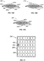
- a plurality of longitudinally spaced separation features is adapted for dividing the wound dressing, and adjacent separation features define a pod there between.
- a plurality of pods may be arranged to define a two dimensional array.
- the contact material may comprise a directionally-apertured film, and the filler material may comprise a polypropylene tow.
- a wound dressing for use with wounds includes a core of filler material comprising a polypropylene tow, a sheath of contact material substantially surrounding the core and comprising a directionally-apertured film, and a seal at a periphery of the sheath of contact material encapsulating the core within the sheath of contact material.
- a wound filler for use with a negative wound pressure therapy apparatus may include a wound dressing for defining a reservoir over a wound in which a negative pressure may be maintained by forming a substantially fluid-tight seal around the wound, a vacuum source in fluid communication with the reservoir and being suitable for providing an appropriate negative pressure to the reservoir to help stimulate healing of the wound, and a wound filler matrix disposed within the wound dressing.
- the wound filler matrix defines a length along a longitudinal axis and comprises at least one continuous fiber configured in a plurality of loop segments traversing the longitudinal axis.
- the wound filler matrix further includes a connecting segment extending along the longitudinal axis and connected to at least some of the loop segments.
- the connecting segment may maintain the integrity of the at least one continuous fiber thereby facilitating placement and removal from the wound bed.
- the connecting segment may be connected to each loop segment.
- the connecting segment may be adapted to be severed to provide a segment of the wound filler matrix to accommodate wounds of various sizes and types.
- the connecting segment may be dimensioned to define a handle segment extending longitudinally beyond the at least one continuous fiber.
- the connecting segment and the at least one continuous fiber may comprise different material.
- the at least one continuous fiber may include multifilaments.
- the at least one continuous fiber of the wound filler matrix may be non-absorbent, and may include an additive.
- a wound dressing apparatus in another embodiment, includes a cover layer adapted to cover a wound to provide a microbial barrier over the wound and a wound filler matrix for receiving wound fluids.
- the wound filler matrix may include a continuous fiber arranged in a tow configured by passing a connecting segment through the fiber to gather the fiber into a plurality of loop segments.
- the present disclosure relates to treatment of a wound using a wound dressing comprising a plurality of fibers, each fiber having a length of at least 5.08cm (two (2) inches) and in one embodiment, at least 10.16cm (4 inches) and in other embodiments, at least 15.24cm (6 inches), and at least 20.32cm (8 inches).
- the method of treatment entails incorporating the wound dressing into a wound to keep the sides of the wound apart, and removing the wound exudate.
- the fiber of the wound dressing may be any fiber having a length of at least 5.08cm (two (2) inches). Included within the suitable fibers are natural fibers and man-made fibers.
- suitable fibers are natural fibers produced by plants, animals and/or geologic processes.
- natural fibers include alginates, chitosan, rayon, vegetable fibers, which may be generated from arrangements of cellulose and bound together by lignin as in cotton, hemp, jute, flax, ramie and sisal, for example.
- wood fibers are derived from tree sources and include groundwood, thermomechanical pulp (TMP) and bleached or unbleached kraft or sulfite (sulphite) pulps formed by a manufacturing process wherein lignin is removed to free the fibers from the wood structure.
- TMP thermomechanical pulp
- sulphite sulfite
- Animal fibers consist largely of proteins and include spider silk, sinew, catgut, wool and hair such as cashmere, mohair and angora, and chitosan for instance.
- mineral sources for natural fibers such as woolastinite, attapulgite, halloysite, and asbestos.
- Suitable man-made fibers include regenerated fibers and synthetic fibers.
- Regenerated fibers are those fabricated from natural materials by processing these materials to form a fiber structure.
- regenerated fibers may be derived from the pure cellulose in cotton and wood pulp to form such products as rayon and cellulose acetates.
- Fibers may also be regenerated from mineral sources such as glass or quartz to form fiberglass or optical fibers.
- Ductile metals such as copper gold or silver may be drawn to form metallic fibers, and more brittle materials such as nickel aluminum or iron may be extruded or deposited.
- Synthetic fibers are made entirely from synthetic materials such as petrochemicals, and are usually stronger than either natural or regenerated fibers. Synthetic fibers (as well as regenerated acetate fibers) tend to be thermoplastic, i.e., they are softened by heat. Therefore, these fibers may be shaped at high temperatures to add such features as pleats, creases and complex cross sections.
- Synthetic fibers may be formed from materials such as polyamide nylon, polyethylene terephthalatae (PET) or polybutylene teraphalate (PBT) polyester, phenolformaldehyde (PF), polyvinyl alcohol (PVOH), polyvinyl chloride (PVC) and polyolefins such as polypropylene (PP) and polyethylene (PE).
- materials such as polyamide nylon, polyethylene terephthalatae (PET) or polybutylene teraphalate (PBT) polyester, phenolformaldehyde (PF), polyvinyl alcohol (PVOH), polyvinyl chloride (PVC) and polyolefins such as polypropylene (PP) and polyethylene (PE).
- the fibers of the wound dressing may be gathered. Gathering of the fibers may be achieved by any known manner. For example, gathering of fibers may be achieved by any one or more of the following methods.
- the fibers may be gathered by entangling the fibers; or intermingling the fibers; or wrapping the fibers with yarn; or thermally bonding the fibers; or ultrasonically treating the fibers; or radio frequency (RF) bonding; or adhering; or tying; or combinations of the methods; and the like.
- RF radio frequency
- fibers may be absorbent or non-absorbent with respect to the wound exudate.
- the fibers may have a denier of about 3 to about 25 deniers per fiber, in one embodiment, and, in another embodiment, from about 3 to about 16 deniers per fiber.
- the fibers may be crimped by any known technique such as, for example, by steam jet crimping, air jet crimping, stuffer box crimping, or self crimping.
- the fibers may be treated to increase the properties of wicking and/or hydrophobicity, by any known technique.
- the fibers may be treated with PHOBOL 7811 aqueous fluorochemical dispersion, available from Huntsman Chemicals.
- the dispersion may be applied to the fiber using a dip and squeeze padder or similar application method.
- the concentration of the dispersion can be adjusted by dilution with water to adjust the level of dispersion applied to the fibers.
- other suitable treatments include the use of hydrophobic aqueous binders such as AIRFLEX 140 available from Air Products, silicones, and a polyurethane such as RU41-773 available from Stahl.
- HYD-REPEL HYD-REPEL
- Goulston Technologies which increases the water repellency property of the fibers. All of the fiber may be treated or a core/sheath fiber may be produced with the HYD-REPEL melt additive in the sheath.
- the fibers herein may be lofted or opened to increase apparent density or volume, by any known technique.
- a material which in the present document is a fiber
- a material which in the present document is a fiber
- the rolls are moving at a speed faster than the speed of the fibers, and the fibers leaving the nip are passed through an air-spreading zone, in which the fibers are confined between two parallel walls.
- the fibers are subjected to streams of air from the walls. This is only one suitable manner of lofting or opening the fibers. Any other means for lofting or opening the fibers may be utilized
- the fibers may be combined with, or treated with, any additive or agent that enhances the healing of the wound.
- agents such as polyhexamethylene biguanide (PHMB), or any other medicaments, antimicrobials, wound healing agents, and/or wound debriding agents, may be used to decrease the incidence of infection or otherwise promote healing of the wound.
- Other agents include those used in slow release treatments wherein the agent is released from the fiber into the wound over a period of time.
- the fibers may contain additional active ingredients or agents such as, for example, a therapeutic agent, an organoleptic agent and a pharmaceutical agent including, for example, an anti-microbial agent, in growth factor, an analgesic, a tissue scaffolding agent, a wound debriding agent, a hemostatic agent, an anti-thrombogenic agent, an anesthetic, an antiinflammatory agent, an anticancer agent, a vasodilation substance, a wound healing agent, an angiogenic agent, an angiostatic agent, an immune boosting agent, a skin sealing agent, combinations thereof and the like.
- a therapeutic agent such as, for example, a therapeutic agent, an organoleptic agent and a pharmaceutical agent including, for example, an anti-microbial agent, in growth factor, an analgesic, a tissue scaffolding agent, a wound debriding agent, a hemostatic agent, an anti-thrombogenic agent, an anesthetic, an antiinflammatory agent, an anticancer agent, a vasodilation substance
- Suitable anti-microbial agents include, but are not limited to, anti-microbial metal ions, a chlorhexidine, a chlorhexidine salt, a triclosan, a polymoxin, a tetracycline, an amino glycoside (e.g., gentamicin or TobramycinTM), a rifampicin, a bacitracin, an erythromycin, a neomycin, a chloramphenicol, a miconazole, a quinolone, a penicillin, a nonoxynol 9, a fusidic acid, a cephalosporin, a mupirocin, a metronidazole, a secropin, a protegrin, a bacteriolcin, a defensin, a nitrofurazone, a mafenide, an acyclovir, a vanocmycin, a clindamycin, a linco
- a preferred anti-microbial agent can include at least one of polyhexamethylene biguanide (PHMB), a PHMB derivative such as, for example, a biodegradable biguanide (e.g., polyethylene hexamethylene biguanide (PEHMB)), chlorhexidine gluconate, chlorohexidine hydrochloride, ethylenediaminetetraacetic acid (EDTA), variations of EDTA such as, for example, disodium EDTA or tetrasodium EDTA, combinations thereof and the like.
- the antimicrobial agent can be PHMB.
- the method for treating wounds using the fibers herein is comprised as fellows.
- the fibers of the wound dressing may be absorbent or non-absorbent with respect to the wound exudate.
- the fibers of the wound dressing may have a denier of about 3 to about 25 deniers per fiber; or may be treated to have increased volume; or may be treated to have increased wicking ability; or may be crimped; or may be lofted; or may be combined with, or treated with, an additive, such as PHMB, that reduces infection of the wound.
- the wound dressing comprising the fibers herein, is incorporated into a wound in any amount that is sufficient to cause the walls of the wound to remain apart thereby allowing the wound to heal from the inside to the outside of the wound.
- the amount of the wound dressing incorporated into the wound ranges from about 25% based on the volume of the wound to an amount of wound dressing that exceeds the volume of the wound.
- the amount of the wound dressing incorporated into the wound ranges from about 50% to about 100% of the volume of the wound, and in another embodiment, the wound dressing is incorporated into the wound in an amount equal to the wound volume.
- the wound dressing that is incorporated into the wound exerts pressure against the walls of the wound.
- the wound exudate be removed from the wound.
- the wound exudate may be removed from the wound by any known technique.
- the wound exudate may be removed by any type vacuum technique such as negative pressure wound therapy (NPWT).
- NGWT negative pressure wound therapy
- the wound exudate may be removed by removing the wound dressing containing the absorbed wound exudate from the wound. In this instance, removal of the wound dressing containing the absorbed wound exudate, may be followed by incorporating a new wound dressing comprised of absorbent fibers, as needed.
- NGWT negative pressure wound therapy
- the wound dressing comprising non-absorbent fibers may be positioned in a reservoir above a wound where a negative pressure may be maintained.
- the reservoir subjects the wound to a sub-atmospheric pressure to effectively draw wound fluid, including liquid wound exudate, from the wound without the continuous use of a vacuum pump.
- Vacuum pressure may be applied once, or in varying intervals, depending on the nature and severity of the wound.
- crimping and bulking methods are contemplated to permit individual fibers or a plurality of fibers to separate in areas such that the fibers may receive and transport wound fluids.
- An air jet crimping process may be used wherein a fiber is directed past turbulent streams of compressed air to entangle the individual fibers into a multitude of loops and convolutions.
- a steam jet crimping process may also be used wherein a fiber is directed past turbulent streams of a high temperature steam to not only produce loops and convolutions, but also to heat set these same loops and convolutions.
- Another crimping process is known as stuffer box crimping.
- Stuffer box crimping is a process by which a fiber may be forcibly fed into a crimping chamber having a restricted exit. Subsequent portions of the fiber entering the crimping chamber will impart a force causing the fiber to buckle inside the chamber until, upon emergence from the chamber, the filter retains a crimp therein. Any of these crimping processes may be used.
- each fiber having a length of at least 5.08cm two (2) inches
- Individual fibers having a length of at least 5.08cm (two (2) inches) will have less tendency to separate from the rest of the fibers. This will minimize loose fibers that might remain in the wound, and which could cause inflammation or other impairments of the wound healing.
- the fibers having a length of at least 5.08cm (two (2) inches) can be gathered to further minimize the possibility of loose fibers remaining in the wound.
- the fibers having a length of at least 5.08cm can be modified for example, by crimping or chemical treatment to provide optimum wound properties that are important to wound healing. These include wound exudate flow, wound exudate retention, conformance to wound, an antimicrobial properties.
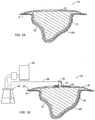
- a wound dressing apparatus for use on a wound "w” surrounded by healthy skin “s".
- the apparatus 10 includes a contact layer 18 placed in contact with the wound "w,” a wound dressing 100 placed into the wound “w” over the contact layer 18 and a cover layer 22 placed in contact with the skin “s” to cover the wound dressing 100 and wound "w.”
- Contact layer 18 may be formed from perforated film permitting exudates to be drawn through the contact layer 18 into the wound dressing 100. Passage of wound fluid through the contact layer 18 may be substantially unidirectional such that exudates do not tend to flow back into the wound "w.” Unidirectional flow may be encouraged by directional apertures, such as cone-shaped formations protruding from the film material (see, e.g. FIG 7 ).
- a non-adherent material may be selected such that contact layer 18 does not tend to cling to the wound "w” or surrounding tissue when it is removed.
- One material that may be used as a contact layer 18 is sold under the trademark XEROFORM® by Tyco Healthcare Group LP (d/b/a Covidien).
- Wound Dressing 100 is positioned in the wound "w” over the contact layer 18 and is intended to receive and retain wound exudates.
- Wound dressing 100 is conformable such that it may assume the shape of any wound “w” and may be packed up to any level, e.g. up to the level of healthy skin “s” or to overfill the wound such that wound dressing 100 protrudes over the healthy skin “s.”
- the wound dressing 100 may be formed from an assembly of fibers each of which fibers having a length of at least 5.08cm (2 inches).
- Cover layer 22 may assume a variety of forms typically used to cover a wound "w" in wound care applications.
- cover layer 22 may be formed from a flexible polymeric or elastomeric film having an adhesive coating on an underside to fasten the film to the surrounding skin "s".
- cover layer 22 may serve as a microbial barrier to help prevent contaminants from entering the wound "w”.
- cover layer 22 may be formed from a moisture vapor permeable membrane to promote the exchange of oxygen and moisture between the wound "w” and the atmosphere.
- a membrane that provides a sufficient moisture vapor transmission rate (MVTR) is a transparent membrane sold under the trade name POLYSKIN®II by Tyco Healthcare Group LP (d/b/a Covidien).
- a transparent membrane helps permit a visual assessment of wound conditions to be made without requiring removal of the cover layer 22.
- cover layer 22 may comprise an impermeable membrane 22.
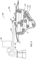
- the wound dressing 100 of the present disclosure may also be used in any wound dressing applications such as a negative pressure wound therapy (NPWT) apparatus 24.
- NGWT negative pressure wound therapy
- Such an apparatus 24 may include a wound dressing having a contact layer 18 and wound dressing 100, as described with reference to Fig. 1A .
- Cover layer 22 may be particularly adapted for such an application.
- cover layer 22 may include a substantially continuous band of a biocompatible adhesive at the periphery 26 such that the adhesive forms a substantially fluid-tight seal with the surrounding skin "s".
- cover layer 22 may act as both a microbial barrier to help prevent contaminants from entering the wound "w", and also a fluid barrier to help maintain the integrity of a vacuum reservoir 28.
- a vacuum port 30 having a flange 34 may also be included to facilitate connection of the reservoir 28 to a vacuum system.
- the vacuum port 30 may be configured as a rigid or flexible, low-profile component, and may be adapted to receive a vacuum tube or fluid conduit 36 in a releasable and fluid-tight manner.
- An adhesive on the underside of flange 34 may provide a mechanism for affixing the vacuum port 30 to the cover layer 22, or alternatively flange 34 may be positioned within reservoir 28 (not shown) such that an adhesive on an upper side of the flange 34 affixes the vacuum port 30.
- the vacuum port 30 is affixed to the cover layer 22, a hollow interior of the vacuum port 30 provides fluid communication between the fluid conduit 36 and the reservoir 28.
- Vacuum port 30 may be provided as a pre-affixed component of cover layer 22, as a component of fluid conduit 36 or entirely independently. Alternatively, vacuum port 30 may be eliminated if other provisions are made for providing fluid communication with the fluid conduit 36.
- Fluid conduit 36 extends from the vacuum port 30 to provide fluid communication between the reservoir 28 and collection canister 40. Any suitable conduit may be used for fluid conduit 36 including those fabricated from flexible elastomeric or polymeric materials. Fluid conduit 36 may connect to the vacuum port 30, the canister 40, or other apparatus components by conventional air-tight means such as friction fit, bayonet coupling, or barbed connectors, for example. The conduit connections may be made permanent, or alternatively a quick-disconnect or other releasable means may be used to provide some adjustment flexibility to the apparatus 10.
- Collection canister 40 may comprise any container suitable for containing wound fluids.
- a rigid bottle may be used as shown, or alternatively a flexible polymeric pouch may be appropriate.
- Collection canister 40 may contain an absorbent material to help consolidate or help contain the wound drainage or debris.
- super absorbent polymers (SAP), silica gel, sodium polyacrylate, potassium polyacrylamide or related compounds may be provided within canister 40.
- At least a portion of canister 40 may be transparent or translucent to assist in evaluating the color, quality and/or quantity of wound exudates. A transparent or translucent canister may thus assist in determining the remaining capacity of the canister or when the canister should be replaced.
- Vacuum source 50 Leading from collection canister 40 is another section of fluid conduit 36 providing fluid communication with vacuum source 50.
- Vacuum source 50 generates or otherwise provides a negative pressure to the NPWT apparatus 24.
- Vacuum source 50 may comprise a peristaltic pump, a diaphragmatic pump or other mechanism that is biocompatible and draws fluids, e.g. atmospheric gasses and wound exudates, from the reservoir 28 appropriate to help stimulate healing of the wound "w.”
- the vacuum source 40 is adapted to produce a sub-atmospheric pressure in the reservoir 28 ranging between about 20 mmHg and about 500 mmHg, more specifically, between about 75 mmHg to about 125 mmHg.
- One suitable peristaltic pump is the Kangaroo PET Eternal Feeding Pump manufactured by Tyco Healtheare Group LP (d/b/a Covidien).
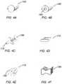
- the wound dressing 100 of the present disclosure may generally assume the form of a bundle, assembly or tow of fibers each of which fibers having a length of at least 2 inches.
- the fibers 102 may be arranged so as to be generally non-intersecting along their length. Although not necessarily parallel, the fibers 102 may be generally free from entanglement or interlacing.
- At least one gathering feature 104 may be included to permit the bundle to help resist separation of fibers 102.
- a single gathering feature 104 may be formed from a separate fiber wrapped or tied around the bundle to compress the bundle in a localized region.
- gathering features 104 may be placed intermittently along the bundle, as shown in FIG. 2B , to help secure the tow at multiple locations, or separate fibers may be wrapped helically around the bundle as in FIG. 2C to form gathering feature 106.
- a tow may be enclosed with a self-sealing, non-woven mesh or other porous sheet to form gathering feature 108.
- a self-sealing gathering feature 108 may be an elastic or slightly undersized band such that fibers 102 may be inserted through an open end of the band to be constrained under compression.
- gathering features 108 may include an adhesive component such that a flat strip may be wrapped around the tow and the flat strip may be affixed by adhering either to itself or to the fibers 102 with the adhesive component.
- a gathering feature 110 may be formed with a substantial length of a non-woven mesh or a porous sheet to enclose a substantial length of the tow.
- the fibers 102 may be arranged or constructed as shown to help permit the tow to resist separation of fibers 102.
- Fibers 102 may be twisted as in a rope to provide a gathering feature 112 ( FIG. 2F ), or fibers 102 may be entangled by various processes to form a gathering feature 114 ( FIG. 2G ). Jets of steam, air or water may be directed at localized regions in the tow to entangle fibers 102 and provide gathering feature 114.
- Another entangling process involves needles used in a manner similar to needle punching to entangle fibers 102.
- a gathering feature 116 ( FIG.
- 2H may be provided simply by bonding fibers 102 with an adhesive, or by incorporating a binding material having a lower melting temperature than the fibers 102. By heating the tow, the binding material may melt and bind the fibers together upon cooling.
- a binding material may be provided along with one or more of the individual fibers in a co-extrusion such as a core-sheath arrangement, as described in greater detail below.
- a gathering feature 118 may also be provided by crimping fibers to provide some degree of entanglement, as described in greater detail below. It is also envisioned that the arrangement of fibers 102 may include two or more of the features shown in FIGS. 2A through 2I .
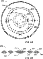
- two or more distinct polymers may be co-extruded to generate a fiber with specialized characteristics.
- a fiber 120 exhibiting a concentric sheath-core arrangement is depicted in FIG. 3A .
- a core polymer 122 is surrounded by a sheath polymer 124.
- sheath polymer 124 may exhibit a lower melting temperature than core polymer 122 such that the sheath polymer 124 may be melted to provide a binder for fibers 102.
- sheath-core arrangement may include providing a high strength structural core polymer 122 and a sheath polymer 124 with surface characteristics appropriate to help promote wicking of wound fluid or to accept any of the beneficial polymer additives discussed below.
- a fiber 126 exhibiting an eccentric sheath-core arrangement is depicted in FIG. 3B including an off-center core polymer 128 and corresponding sheath polymer 130. This arrangement may be used to provide a self-crimping fiber 126 when the core polymer 128 and sheath polymer 130 are provided with differing shrinkage characteristics when subject to a temperature change.
- Fiber 132 is similar to fiber 126, but differs in that core polymer 134 and sheath polymer 136 each occupy a portion of the outer surface of the fiber 132. With a proper polymer selection, the side-by-side arrangement of fiber 132 may yield higher levels of latent crimp than the eccentric sheath-core arrangement of fiber 126.
- a fiber 138 having a pie-wedge arrangement may include alternating wedges comprising polymers 140 and 142.
- the wedges may be split into the component wedges upon mechanical agitation. This may assist in forming a gathering feature 114 as discussed above with reference to FIG. 2G .
- the component wedges may yield localized areas of microfibers to assist in entangling the fiber 138.
- a fiber 144 exhibiting a hollow pie wedge arrangement including a hollow center core is depicted in FIG. 3E . Fiber 144 may require less agitation to split into component polymers 146, 148.
- fiber 150 exhibits an islands-in-the-sea arrangement where one or more "island" polymers 152 are surrounded by a soluble "sea" polymer 154.
- This arrangement may provide for very fine strands of island polymers 152 to be effectively handled by manufacturing equipment. Once the island polymers 152 are in place, the soluble sea polymer is dissolved away. As many as about 37 or more island polymers 152 having a denier of about 0.04 (roughly 2 microns in diameter) may thus be handled effectively as a single fiber 150.
- a fiber 156 exhibits a "three island” arrangement, as depicted in FIG. 3G .
- This arrangement includes three island polymers 158 surrounded by a sea polymer 160.
- Fiber 156 may be used in a manner similar to fiber 150 exhibiting an islands-in-the-sea arrangement, but may be more commonly used in a manner similar to fibers 120, 126 and 132 described above exhibiting a sheath-core arrangement.
- Fiber 156 may be described as including three core polymers 158 collectively having an increased surface area to discourage de-lamination from a potentially incompatible sheath polymer 160.
- individual fibers 102 may exhibit various cross sections to enhance a wicking capability or another characteristic of wound filler 100.
- a solid round cross section as depicted in FIG. 4A may be a standard for most synthetic fibers due to a relatively low cost when compared to another modified cross sections below.
- a fiber 162 is depicted in FIG. 4B having a void 164 in its cross section. Void 164 runs the entire length of the fiber 162 yielding a reduced density and rigidity of fiber 162 and permitting air to be trapped within. Such a cross section may facilitate crimping, entangling and/or lofting processes.
- a multi-lobal cross section may also be used as depicted in FIG. 4C .
- Tri-lobal fiber 168 exhibits three arms 170 projecting from a central region offering rigidity and resilience to the wound dressing 100.
- a ribbon cross section as exhibited by fiber 174 depicted in FIG. 4D may be described as exhibiting a bi-lobal arrangement.
- a ribbon cross section offers a bending direction and shape well suited for segmented fibers which may be split into micro-fibers as described above with reference to FIGS. 3D and 3E . Such a cross section may be split into micro-fiber components with relatively minor agitation when compared to other cross sections.
- Highly modified cross section fibers 178 as depicted in FIG. 4E are sold under the trade name 4DGTM by Fiber Innovation Technology, Inc. Deep channels 180 of various sizes and configurations are provided along a longitudinal axis of the fiber 178 to help promote capillary TM wicking with its relatively large surface area. Fibers 172 having a 4DG cross section have demonstrated a capability to transport up to 2 liters of water per hour per gram of fiber.
- a fiber 184 having a bowtie cross section as depicted in FIG. 4F may be well suited for use in a self-crimping fiber as described above with reference to FIG. 3B and FIG. 3C .
- Polymers with differing thermal characteristics may be arranged such that the centers of mass of the two polymers are separated by a relatively greater distance than other cross sections.
- a fiber 184 thus arranged may exhibit enhanced stretch recovery of the helical coils formed by heating and subsequently cooling the fiber 184.
- Self crimping may be accomplished with an eccentric core-sheath arrangement of polymers described above with reference to FIG. 3B or a side-by-side arrangement as described with reference to FIG. 3C .
- Another option to produce a self crimping tow is to combine full fibers of differing thermal characteristics in a creeling process.
- the crimped tow may be opened, i.e., the crimped fibers may be separated or spaced, to produce a particular texture or bulk.
- the crimped tow may be opened by air jets, or by longitudinal stretching and relaxing of the tow with a threaded roll assembly.
- Apparatus 200 includes a wound dressing assembly 202 defining reservoir 28 in fluid communication with vacuum source 50 as described above with reference to FIG. 1B .
- Wound dressing assembly 202 includes an elongate wound packing structure 210 comprising a core 212 substantially surrounded by a sheath 214.
- the core 212 may be formed from a dressing or filler material adapted for receiving and/or transporting wound exudates, and may include any material or structure described above with reference to FIG. 1A for use with wound dressing 100.
- the sheath 214 may be formed from a contact material 214 adapted for positioning in contact with the wound "w,” and may include any material or structure described above with reference to FIG. 1A for use with contact layer 18.
- the sheath 214 is permeable to permit passage of wound fluids into and out of the core 212 of filler material
- the packing structure 210 may be embodied as an elongate tube arranged to follow a winding path to substantially fill the wound "w" and conform to the particular geometry of the wound "w.” Such an elongate tube may be provided in continuous lengths that may be conveniently cut at the time wound dressing assembly 202 is applied to accommodate the particular size of the wound "w.” Such an arrangement may not require separate and independent sizing and subsequent application of a wound contact layer 18 and wound dressing 100.
- packing structure 210 defines an elongate tube having a length "L" extending in a longitudinal direction and a maximum width "A" extending in a lateral direction.
- the oblong cross section of packing structure 210 is substantially consistent along the length "L" of the packing structure 210.
- Other cross sections may be appropriate such as a round, hexagonal or other polygonal shapes.
- the sheath 214 may be formed by an extrusion or similar process providing for a seamless circumference around the core 212.
- Packing structure 220 depicted in FIG. 6B , includes a core of filler material 222 substantially surrounded by a sheath of contact material 224.
- a plurality of longitudinally spaced separation features 226 provide for dividing the packing structure 220.
- a separation feature 226 may comprise a perforated tear line extending laterally across packing structure 220, which a clinician may use to cut or tear away a portion of the packing structure 220 such that packing structure 220 has an appropriate length to fill a wound "w" of a particular size. Separation features 226 may be spaced apart, for example, by a distance "D" of from about 50 percent to about 300 percent of a width "B" of the packing feature 220.
- a series of pods 228 may be defined between adjacent separation features 226.
- Each pod 228 may have an open configuration wherein the core of filler material 222 extends between adjacent pods through the separation features 226. A portion of the dressing material 222 may thus be exposed across a lateral edge of the packing structure 220 when an adjacent pod 226 is removed.
- each pod 228 may have a closed configuration where in the core of filler material 222 is interrupted in the vicinity of the separation feature 226.
- the sheath of contact material 224 may be sealed to itself on the interior of packing structure 220 in the vicinity of the separation feature 226, such that the sheath of contact material 224 extends along opposite lateral edges of the pods 228.
- Such an arrangement of closed pods 228 may provide an area of increased flexibility in the vicinity of the separation feature 226 when compared to a central region of the pods 228.
- An area of increased flexibility may facilitate placement of packing structure 220 in a winding arrangement within the wound "w.”
- packing structure 230 includes a core of filler material 232 substantially surrounded by a sheath of contact material 234.
- a separation feature 236 may comprise a slit or series of longitudinally spaced slits extending laterally across packing structure 230. Slits 236 may extend partially into the filler 232 such that the packing structure 230 is less resistant to cutting or tearing in the vicinity of the slits 236.
- the sheath of contact material 234 may be arranged with an overlap 238. Overlap 238 may facilitate application of a longitudinal adhesive bond, ultrasonic weld or similar seal to facilitate assembly of packing structure 230.
- packing structure 240 includes a core of filler material 242 substantially surrounded by a sheath of contact material 244.
- the sheath of contact material 244 includes upper and lower sheets 244U and 244L of contact material with a heat seal 246 formed around the periphery of the sheath 244 to encapsulate the filler 242 therein.
- An adhesive bond, ultrasonic weld, or similar seal may be incorporated as an alternative or in combination with heat seal 246 to encapsulate the filler 242.
- Packing structure 240 is a generally round, saucer or puck shaped capsule, but may alternatively be formed into a variety of shapes including spheres, cylinders, cubes, tetrahedrons and other polygonal shapes.
- Filler 242 assumes the form of a polypropylene tow.
- a tow may be described as a loose, essentially untwisted strand of a large number of unidirectional synthetic fibers.
- Continuous filament polypropylene fibers may be arranged to form a loosely entangled ball to form a filler 142 capable of receiving wound exudates.
- the tow may be crimped, bulked or lofted to influence the absorptive, wicking or comfort characteristics of the filler 142.
- FIGS. 2A through 4F Various such processes and arrangements for the tow of filter 242 are described above with reference to FIGS. 2A through 4F .
- Sheath 244 is formed from a non-adherent, direciionally-apertured polyolefin film such as those manufactured by Tredegar Film Products, Corp. of Richmond, VA. These films are safe for contact with a wound "w" and permit fluid to flow into the filler 242. Unidirectional flow is encouraged through such a film by apertures formed at the peak of cone-shaped formations in the film material that project in one direction. Such a film will thus have a male side, as depicted in FIG. 7C , and an opposite female side. Fluid flow is encouraged across the film from the female side to the male side and discouraged in the opposite direction. Sheath 244 may be arranged such that the male side of such a film faces the interior of packing structure 240 from all directions.
- the lower sheet 244L of sheath 244 may be oriented such that the male side faces the interior of the packing structure 240, while the upper sheet 244U of sheath 244 is oriented such that the male side faces the exterior of the packing structure 240. This arrangement encourages unidirectional flow through the entire packing structure 240.
- wound fluids may be encouraged to flow into packing structure 240 by the directional apertures in the lower sheet 244L, and subsequently wicked through filler 242 to the upper sheet 244U where the directional apertures encourage flow out of the packing structure 240.
- Wound fluids may then be removed from wound dressing assembly 202 by vacuum source 50 and deposited in canister 40 ( FIG. 5 ). Regardless of the orientation of upper and lower sheets 244U and 244L, sheath 244 should be pliable and soft when heat sealed such that packing structure 240 does not cause pain to the patient when placed inside a wound "w.”
- packing structure 250 includes a core of filler material 252 substantially surrounded by a sheath of contact material 254.
- a plurality of ring-shaped interior heat seals 256 are formed in a generally concentric arrangement between discrete segments of the filler material 252, thus dividing the packing structure 250 into a number of pods.
- a central pod 258 lies in the center of the packing structure 250, and is encircled by progressively larger ring-shaped pods 260, 262 toward the circumferential regions of the packing structure 250.
- An exterior heat seal 264 is formed around the periphery of packing structure 250 to close the outermost pod 262.
- a perforated ring 268 is formed on each of the interior heat seals 256 to provide a separation feature for the pods.
- packing structure 250 is depicted as including only three distinct pods 258, 260 and 262, any number of pods may be formed into such an arrangement to form a packing structure of any desired size.
- Heat seals 256, 264 may have a width "X" of about 1 cm or less, and may be separated by a distance "Y" of about 1 inch to about 2 inches.
- outer pods, e.g. 262 may be removed using perforated ring 268 to permit packing structure 250 to assume an appropriate size for the wound "w.”
- a mold “m” may be formed as depicted schematically (in cross-section) in FIG. 9A .
- the mold “m” may include indentations "i" on an upper surface thereof, which are sized and spaced appropriately to form a desired number of pods.
- the mold depicted in FIG. 9A may be used to form a packing structure with four distinct pods including a central pod and three surrounding ring shaped pods.
- a flat sheet of sheath material 254L may be placed over the mold "m" ( FIG. 9B ) with a male side facing up.
- a directionally-apertured film such as those manufactured by Tredegar Film Products may be provided with, or marked with a distinguishing color on each side such that a proper orientation of the sheet may be verified.
- the sheet of sheath material 254L may then be drawn into the indentations "i" ( FIG. 9C ). Airflow may be directed through the mold "m” to draw in the sheath material 254L, or the sheath material 254L may be urged into place by any other suitable means.
- the filler material 252 may be positioned in the indentations "i" over the sheath material 254L, and may be arranged to overfill the indentations as depicted in FIG. 9D .
- a central indentation "i” may accommodate an entangled mass of polypropylene tow while surrounding indentations "i” may be conveniently filled by a twisted or spun rope of the tow material arranged in a circular fashion.
- Another sheet of the sheath material 254U may be placed over the filler 252, and may be drawn downward into the intermediate spaces between the indentations in the mold "m" ( FIG. 9E ).
- the male side of the upper sheet of sheath material 254U may face downward toward the filler, and toward the male side of the lower sheet of sheath material 254L.
- An appropriate heat sealer "h” FIG. 9F ) having appropriately sized heat sealing rings may then be pressed down into each of the intermediate spaces to form interior heat seals 256, and another heat sealing ring may similarly form exterior heat seal 264.
- the heat sealing rings may include a Teflon® or similar coating such that the sheath material 254U does not tend to stick to the heat sealing rings.
- the heat sealing rings may alternately be applied individually, or the heat seals 256, 264 may be replaced by seals formed with a laser or ultrasonic welding mechanism that traverses a path around the filler 252 to encapsulate the filler 252.
- the filler and the sheath material may be removed from the mold "m” for further processing.
- the structure may be delivered to another apparatus for forming perforated rings 268 to complete the packing structure.
- the mold "m” or the heat sealer “h” may include a perforating mechanism (not shown) to form perforated rings 268 along with the formation of the heat seals 256, 264.
- the filler 252 may not necessarily overfill the indentations "i,” but may be fill the indentations "i" up to the level of the top surface of the mold "m.”
- the upper layer of sheath material 254U may be replaced with a material that is dissimilar to the lower layer of sheath material.
- the lower layer of sheath material 254L may be formed of a directionally-apertured polyolefin film while the upper layer may be formed of a porous or nonporous sheet of a polypropylene.
- packing structure 260 includes a core of filler material 262 substantially surrounded by a sheath of contact material 264.
- the sheath of contact material 264 includes upper and lower sheets 264U and 264L of contact material with a seal 246 formed around the periphery to encapsulate the filler 262 therein.
- the upper and lower sheets 264U and 264L may be formed from a directionally-apertured film and may be oriented as discussed above.
- Filler 262 may be distinguished in that filler 262 is formed from at least two distinct materials.
- Filler 262 comprises a layer of polypropylene tow is designated 262T, and a layer foam is designated 262F.
- Tow layer 262T may take any form discussed above with reference to FIG. 7A
- foam layer 262F may be formed from a resilient, open-cell foam such as polyurethane, polyester or polyolefin foam.
- Foam layer 262F may be effective to receive wound fluids from the wound, and may also readily release the wound fluids such that they may be removed from a dressing assembly 202 by a vacuum source 50 (see FIG. 5 ).
- Foam layer 262F exhibits uniform compression when subject to the evacuation cycles of an NWPT treatment such that potentially painful pressure points in the packing structure 260 are managed and the periphery of the wound 'w" may be drawn inward evenly.
- the foam layer 262F may be positioned adjacent the lower sheet 264L of sheath 264 as depicted in FIG. 10A to provide a cushion to the wound bed.
- Alternative structures include a packing structure 270, which may include a filler 272 having a foam layer 272F on each side of a tow layer 272T.
- Packing structure 280 also includes a filler 282 having a foam layer 282 on each side of a tow layer 282T.
- a hole 282H is formed in each foam layer 282 to promote the flow of exudates through the packing structure 280.
- packing structure 290 includes a core of filler material 292 substantially surrounded by sheath of contact material 294.
- a seal 296 is formed in the sheath of contact material 294 such that a plurality of pods 298 are formed in a two dimensional array.
- Pods 298 may vary in size, but are preferably about 1.25 inches in length by about 1.25 inches in width or smaller to provide a customizable packing structure 290.
- unnecessary pods 298 may be cut away to accommodate smaller wounds "w,” or pods 298 may be folded onto one another along the seal 296 to accommodate deeper wounds "w.”
- Perforations may be formed in the sheath 294 along the seal 296 to provide a separation feature to facilitate removal of unnecessary pods 298.
- sheath 294 may be free of perforations to increase the strength and integrity of packing structure 290 inside a wound "w.”
- a separation feature may thus be provided by creating a seal 296 wide enough to be readily cut by a clinician without inadvertently cutting into the core of filler 292.
- a packing structure 290 without perforations helps to insure individual pods 298 do not inadvertently become detached from the packing structure 290, and thus decreases the probability that a pod 290 will be inadvertently left in the wound "w.”
- a wound filler matrix 300 of the present disclosure as depicted in FIG. 12 incorporates at least one continuous fiber comprising either natural or man-made filaments to form a structure suitable for conveying, transferring, and/or absorbing exudates.
- continuous filaments include those relatively long strands of a synthetic material such as nylon, rayon, etc., which may offer a smooth continuous outer surface substantially free of the protruding fibrils commonly associated with natural materials such as cotton. Because of the relatively smooth surfaces, structures such as fabrics or yarns formed from continuous filaments have a substantially lower tendency to become attached to a healing wound bed than do structures formed from natural filaments. Also, because of the relatively long length, continuous filaments have a substantially lower tendency to become separated from a structure and be inadvertently deposited in a wound as the dressing is changed.
- the wound filler matrix 300 of the present disclosure may generally assume the form of a bundle, assembly, or tow of a continuous fiber. As illustrated in FIG. 12 , the wound filler matrix 300 defines a length along longitudinal axis "x" about which at least one fiber 301 is disposed. Fiber 301 may be configured in a plurality of loop segments 303 which are arranged to traverse longitudinal axis "x.” A connecting segment 305 extends along longitudinal axis "x" and is connected to at least several, possibly, all of the loop segments 303. Connecting segment 305 may be parallel or coincident to longitudinal axis "x". Connecting segment 305 may be stitched, pulled, tied, gathered, adhered ( FIG.
- Connecting segment 305 may extend beyond the effective length of fiber 301 thereby providing an extension 307 or handle which may be grasped by the clinician to facilitate placement and/or removal of the wound filler matrix 100 relative to the wound bed.
- the connecting segment 305 prevents the filament(s) and/or fibril(s) of the fiber from releasing from matrix 300 thereby minimizing the potential of the filaments remaining in the wound "w" upon removal of the material therefrom.
- Wound filler matrix 300 may be severed at any predetermined longitudinal location to accommodate wounds of various sizes. With this arrangement, multiple size wounds may be accommodated with a single matrix 300.
- wound filler matrix 300 may be cut to provide a specific dimensioning to accommodate a specific wound type, e.g., for a tunneling or deep wound. It may be desirable to sever the matrix at a location along the longitudinal axis (e.g., location "k") such that a portion 305a of connecting segment 305 extends from the last loop. This may facilitate placement and/or subsequent removal of the reduced matrix segment 300a.
- Wound filler matrix 300 may be severed at several locations along the longitudinal axis "x" depending on the overall length of the wound filler matrix 300 provided and the wound type and/or size.
- the fibers 301 of wound filler matrix 300 may be formed from mono- or multi- filaments 302.
- a multifilament is more than one strand of material that has been twisted, bonded, or otherwise placed together to form a fiber as illustrated above in FIGS. 2A-2I .
- Each of the embodiments of fiber 301 depicted in FIGS. 13A-13I correspond to the multifilimant arrangements of FIGS. 2A-2I , and may be arranged in the sinusoidal configuration depicted in FIG. 12 and attached via a connecting segment 305.
- the filaments 102 of wound filler matrix 100 may take a wide variety of forms. Materials may be classified generally into two basic types including natural fibers and man-made fibers. Further, natural and man-made fibers include both absorbent and non-absorbent varieties as within the purview of those skilled in the art. Natural fibers are those produced by plants, animals and/or geologic processes. For example, natural fibers include vegetable fibers, which may be generated from arrangements of cellulose and bound together by lignin as in cotton, hemp, jute, flax, ramie and sisal, for example.
- wood fibers are derived from tree sources and include groundwood, thermomechanical pulp (TMP) and bleached or unbleached kraft or sulfite (sulphite) pulps formed by a manufacturing process wherein lignin is removed to free the fibers from the wood structure.
- Animal fibers consist largely of proteins and include spider silk, sinew, catgut, wool and hair such as cashmere, mohair and angora, for instance.
- mineral sources for natural fibers such as wollastinite, attapulgite, halloysite, and asbestos.
- Man-made fibers include regenerated fibers and synthetic fibers.
- Regenerated fibers are those fabricated from natural materials by processing these materials to form a fiber structure.
- regenerated fibers may be derived from the pure cellulose in cotton and wood pulp to form such products as Rayon and cellulose acetates.
- Fibers may also be regenerated from mineral sources such as glass or quartz to form fiberglass or optical fibers.
- Ductile metals such as copper gold or silver may be drawn to form metallic fibers, and more brittle materials such as nickel aluminum or iron may be extruded or deposited.
- Synthetic fibers are made entirely from synthetic materials such as petrochemicals, and are usually stronger than either natural or regenerated fibers. Synthetic fibers (as well as regenerated acetate fibers) tend to be thermoplastic, i.e., they are softened by heat. Therefore, these fibers may be shaped at high temperatures to add such features as pleats, creases and complex cross sections.
- Synthetic fibers may be formed from materials such as polyamide nylon, polyethylene terephthalatae (PET) or polybutylene teraphalate (PBT) polyester, phenolformaldehyde (PF), polyvinyl alcohol (PVOH), polyvinyl chloride (PVC) and polyolefins such as polypropylene (PP) and polyethylene (PE).
- materials such as polyamide nylon, polyethylene terephthalatae (PET) or polybutylene teraphalate (PBT) polyester, phenolformaldehyde (PF), polyvinyl alcohol (PVOH), polyvinyl chloride (PVC) and polyolefins such as polypropylene (PP) and polyethylene (PE).
- Connecting segment 305 of wound filler matrix 300 may also take a wide variety of forms including the types and materials described above. Connecting segment 305 may be formed from the same or a different material as fiber 101.
- any commercial fiber or suture material may advantageously be employed in wound matrix 300.
- a non-exhaustive list of materials includes, but are not limited to, polymers and polymer blends selected from the group consisting of polyolefins (such as polyethylene and polypropylene including atactic, isotactic, syndiotactic, and blends thereof as well as, polyisobutylene and ethylene-alphaolefins copolymers, and fluorinated polyolefin such as polytetrafluoroethylene); polyesters (such as polyethylene terephthalate and polybutylene terephthalate); acrylic polymers and copolymers; modacrylics; vinyl halide polymers and copolymers (such as polyvinyl chloride); polyvinyl ethers (such as polyvinyl methyl ether); polyvinylidene halides (such as polyvinylidene fluoride and polyvinylidene chloride); polyacryl
- Various polymer additives may be applied to individual mono- or multi- filaments 102, any of the filaments described above or a matrix 300 to enhance the healing of wound "w.”
- agents such as polyhexamethylene biguanide (PHMB) or other medicaments, antimicrobials, wound healing agents and wound debriding agents may be used to decrease the incidence of infection or otherwise promote healing of the wound "w.”
- agents may include those agents for use in slow release treatments wherein the agent is released from the matrix material into the wound over time.
- Hydrolysis stabilizers may be incorporated to control the release of an agent or to maintain the integrity of the tow.
- wetting agents may be applied to promote a moist wound environment.
- additives may facilitate the removal of matrix 100 from the wound.
- silicone or floropolymers such as PTFE may be added to provide filaments 102 with a slicker surface.
- a slicker surface may help allow the tow to conform comfortably to the shape of the wound "w.”
- Still other additives may facilitate construction of the wound filler matrix 100 such as compatibilizers and adhesion promoters.
- Still other additives such as phase change materials, nanoparticles, UV-absorbers and sunblocks, stain resistant agents or flame retardants may find additional utility when in a wound matrix 300.
- a creel may include a plurality of spindles projecting in a vertical direction from a base frame to accept spools with an internal void, such that the spools may spin about the spindles to pay out a length of the filament.
- Such a manufacturing process provides an opportunity to combine filaments to produce a tow with specific characteristics.
- One or more of the spools may simply be stocked with a filament having differing characteristics than other spools on the creel.
- Filaments of differing denier per filament may be combined to produce a fiber with a specific total denier, e.g., from about 1000 to about 10,000.
- the denier per filament may be conveniently adjusted to control fluid flow properties and the resiliency of matrix 100 when subject to application or removal pressure.
- an exact number of filaments having a relatively low melting temperature may be incorporated into a creeling process to provide precise control over the adhesive properties that such filaments may provide when melted.
- Mixing of different polymers such as polypropylene with high tenacity PET is contemplated to control tow characteristics such as strength and wicking capability of a tow.
- a single filament or any number of filaments coated with an additive or healing agent described above may be incorporated into a fiber to promote healing of the wound "w." Any number of combinations of any of the filaments described above in any quantity may be assembled to produce a tow with the exact characteristics desired.
- porous membrane tubes may be inserted into or over a multifilament fiber to provide a bonding feature.
- twisted filaments, filaments with differing crimp patterns, or crimp patterns with differing spacing may be combined to form a fiber for use as matrix 300.
- crimping and bulking methods are contemplated to permit the fiber of a tow to separate in areas such that the tow may receive and transport wound fluids.
- An air jet, or steam jet crimping process, or any of the crimping processes described above may be used to impart an S- or Z-type crimp to the fiber.
- S- and Z-type crimps refer to a direction of crimping such that the crimped fiber form a zig-zag pattern that resembles either letter "S" or letter "Z.”
- Self crimping may be accomplished with an eccentric core-sheath arrangement of polymers described above with reference to FIG. 3B or a side-by-side arrangement as described with reference to FIG. 3C .
- Another option to produce a self crimping fiber is to combine full filaments of differing thermal characteristics in a creeling process.
- the crimped fiber may be opened, i.e., the loop segments of crimped fiber may be separated or spaced, to produce a particular texture or bulk.
- the loop segments of crimped fiber may be opened by air jets, or by longitudinal stretching and relaxing of the fiber with a threaded roll assembly.
- An embodiment of the present disclosure comprises a multifilament fiber tow formed from primarily round cross section polypropylene filaments with a denier per filament from about 6 to about 10, e.g., about 8.
- the fiber may be crimped with either an S or Z- type crimp, and the loop segments may be lofted or opened by air jets or by stretching and relaxing.
- the fiber may be creeled from multi-filament yarns including a sufficient number of individual filaments to exhibit a yarn denier of about 300. About 100 spools of the about 300 denier yarns may be creeled to form a total tow denier of about 30,000.
- the yarns on about 30 of the spools may be treated with an antimicrobial such as PHMB, while the yarns on the remaining about 270 spools may be untreated.
- the fiber may be encapsulated in a spun polypropelene non-woven web to minimize the effect of loose filaments protruding from the tow.
- Alternatives include a similar fiber subject to air jet entanglement rather than encapsulation, and also a fiber in which substantially all of the yarns or filaments are treated with PHMB.
- wound filler matrix 300 may be used independent of the other components of the wound dressing 10 or may be used in combination with cover layer 22 and/or contact layer 18.
- Wound filler matrix 300 may be used as a wound bandage in the absence of negative pressure therapy, e.g., as a wound covering in a conventional application. Other uses are also envisioned.
Landscapes
- Health & Medical Sciences (AREA)
- Heart & Thoracic Surgery (AREA)
- Engineering & Computer Science (AREA)
- General Health & Medical Sciences (AREA)
- Veterinary Medicine (AREA)
- Vascular Medicine (AREA)
- Life Sciences & Earth Sciences (AREA)
- Animal Behavior & Ethology (AREA)
- Biomedical Technology (AREA)
- Public Health (AREA)
- Anesthesiology (AREA)
- Hematology (AREA)
- Chemical & Material Sciences (AREA)
- Medicinal Chemistry (AREA)
- Manufacturing & Machinery (AREA)
- Materials For Medical Uses (AREA)
- Media Introduction/Drainage Providing Device (AREA)
- External Artificial Organs (AREA)
Description
- This application claims priority to, and the benefit of,
U.S. Provisional Application Serial Nos. 61/188,370 filed on August 8, 2008 by Heagle 61/096,105 filed on September 11, 2008 by Corley 61/147,179 filed on January 26, 2009 by Watson - The present disclosure relates generally to wound dressings, and in particular to a wound dressing including an assembly or tow of continuous long fibers for receiving and retaining wound fluids in the treatment of acute and chronic wounds.
- Wound dressings are generally placed over a wound to protect and promote healing of the wound. In the case of exuding wounds, such as pressure sores, ulcers and burns, it is customary to provide a dressing having a packing or filler material for receiving, retaining or conveying the wound exudate as it is produced. Exudates may be conveyed from the wound bed, at least in part, due to wicking characteristics of the wound filler. Thus, the wound filler promotes healing by removing potentially harmful bacteria from the wound bed, and also prevents damage to the surrounding skin that can be caused by an excessively moist environment.
- The dressing filler may capture the excess exudates for subsequent removal, e.g., when the dressing is replaced with a new dressing. Some materials, such as cotton, tend to shed fibers or fibrils (e.g., very short or irregular fibers jutting out from the main fiber structure) into the wound. These fibers may tend to remain in the wound when the dressing is changed. Removing these stray fibers can be a labor intensive procedure that may further damage the wound, and neglecting to remove these stray fibers may cause irritation and otherwise inhibit natural healing of the wound.
- One technique that may utilize a dressing with an absorbent filler is known as negative wound pressure therapy (NWPT). The absorbent material may be positioned in a reservoir over the wound where a negative pressure may be maintained. The reservoir subjects the wound to a sub-atmospheric pressure to effectively draw wound fluid, including liquid exudates, from the wound without the continuous use of a vacuum pump. Hence, vacuum pressure may be applied unce, or in varying intervals depending on the nature and severity of the wound. This technique has been found to promote blood flow to the area, stimulate the formation of granulation tissue and encourage the migration of healthy tissue over the wound. An NWPT apparatus may also serve to draw exudates from the absorbent material out of the dressing without requiring that the entire dressing be changed. When an NWPT procedure is complete, however, the absorbent material must be removed and is thus subject to the difficulties that may be caused by stray fibers. Accordingly, an absorbent filler suitable for use in wound dressings including those wound dressings adapted for use in advanced wound therapy procedures such as NWPT would be helpful.
- The invention is as claimed in the claims.
- According to one example of the disclosure, a method for treating a wound includes using a wound dressing comprising a plurality of fibers, each fiber having a length of at least two (2) inches. The method entails incorporating the wound dressing into a wound to keep the sides of the wound apart, and removing the wound exudate.
- According to another example of the disclosure, a wound dressing apparatus is configured to promote the healing of a wound, and may be used in conjunction with an NWPT system. The apparatus includes a wound cover for defining a reservoir over a wound in which a negative pressure may be maintained by forming a substantially fluid-tight seal around the wound, a vacuum source in fluid communication with the reservoir and suitable for providing an appropriate negative pressure to the reservoir to stimulate healing of the wound, and a packing structure positioned between the wound and the wound cover. The packing structure includes a core of filler material substantially surrounded by a sheath of contact material. The filler material is adapted for receiving wound fluids, and may be adapted for transporting wound fluids from the wound. The sheath of contact material is adapted for direct contact with the wound, and is permeable to wound fluids to permit passage of wound fluids through the core.
- The packing structure may define an elongate tube, and may exhibit a plurality of longitudinally spaced separation features adapted for dividing the packing structure. A pod defined between adjacent separation features may assume a closed configuration such that the sheath of contact material extends along opposite lateral edges of the pod. The separation features include a perforated tear line extending laterally across the packing structure and may be spaced apart from adjacent separation features by a distance of from about 50% to about 300% of a width of the packing feature.
- In some embodiments of the disclosure, the contact material may comprise a directionally-apertured film, and the filler material may comprise a polypropylene tow. The sheath may comprise upper and lower sheets of the directionally-apertured film having a seal around a periphery to encapsulate the filler between the upper and lower sheets, and each of the upper and lower sheets may be arranged such that a male side of the directionally-apertured film is oriented toward the interior of the packing structure to encourage exudate flow into the packing structure. Other non-adherent materials are also envisioned. Alternatively, one of the upper and lower sheets may be arranged such that a male side of the directionally-apertured film is oriented toward the interior of the packing structure, and the other of the upper and lower sheets may be arranged such that a male side of the directionally-apertured film is oriented toward the exterior of the packing structure to encourage exudate flow through the packing structure. The packing structure may comprise upper and lower sheets of contact material having a seal around a periphery to encapsulate the filler material between the upper and lower sheets. Furthermore, the packing structure may comprise at least one interior seal to define a central pod that is encircled by at least one ring-shaped pod toward a circumferential region of the packing structure. A separation feature may be included on the seal. A plurality of progressively larger ring-shaped pods toward the circumferential region of the packing structure may be defined by a plurality of generally concentric interior seals.
- The filler may include a foam layer adjacent one of the upper and lower sheets of contact material, and a tow layer adjacent the foam layer. A foam layer may be disposed on each side of the tow layer, and a hole may be formed in the foam layer to promote the flow of wound fluids through the packing structure.
- According to another example of the disclosure, a wound dressing for use with wounds includes a core of filler material, and a sheath of contact material substantially surrounding the core. The core of filler material is adapted for receiving wound fluids, and may also be adapted for transporting wound fluids from the wound. The contact material is adapted for positioning in direct contact with the wound, and the sheath is permeable to permit passage of the wound fluids into and through the core. A plurality of longitudinally spaced separation features is adapted for dividing the wound dressing, and adjacent separation features define a pod there between. A plurality of pods may be arranged to define a two dimensional array. The contact material may comprise a directionally-apertured film, and the filler material may comprise a polypropylene tow.
- According to still another example of the disclosure, a wound dressing for use with wounds includes a core of filler material comprising a polypropylene tow, a sheath of contact material substantially surrounding the core and comprising a directionally-apertured film, and a seal at a periphery of the sheath of contact material encapsulating the core within the sheath of contact material.
- According to another example of the disclosure, a wound filler for use with a negative wound pressure therapy apparatus, e.g., may include a wound dressing for defining a reservoir over a wound in which a negative pressure may be maintained by forming a substantially fluid-tight seal around the wound, a vacuum source in fluid communication with the reservoir and being suitable for providing an appropriate negative pressure to the reservoir to help stimulate healing of the wound, and a wound filler matrix disposed within the wound dressing. The wound filler matrix defines a length along a longitudinal axis and comprises at least one continuous fiber configured in a plurality of loop segments traversing the longitudinal axis. The wound filler matrix further includes a connecting segment extending along the longitudinal axis and connected to at least some of the loop segments. The connecting segment may maintain the integrity of the at least one continuous fiber thereby facilitating placement and removal from the wound bed. The connecting segment may be connected to each loop segment. The connecting segment may be adapted to be severed to provide a segment of the wound filler matrix to accommodate wounds of various sizes and types. The connecting segment may be dimensioned to define a handle segment extending longitudinally beyond the at least one continuous fiber.
- The connecting segment and the at least one continuous fiber may comprise different material. The at least one continuous fiber may include multifilaments. The at least one continuous fiber of the wound filler matrix may be non-absorbent, and may include an additive.
- In another embodiment, a wound dressing apparatus includes a cover layer adapted to cover a wound to provide a microbial barrier over the wound and a wound filler matrix for receiving wound fluids. The wound filler matrix may include a continuous fiber arranged in a tow configured by passing a connecting segment through the fiber to gather the fiber into a plurality of loop segments.
- The accompanying drawings, which are incorporated in and constitute a part of this specification, illustrate embodiments of the present disclosure and, together with the detailed description of the embodiments given below, serve to explain the principles of the disclosure.
-
FIG. 1A is a cross sectional view of a wound dressing apparatus formed in accordance with the present disclosure; -
FIG. 1B is a cross sectional view of an alternate wound dressing apparatus formed in accordance with the present disclosure; -
FIGS. 2A through 2I are partial orthogonal views depicting various configurations for a wound filler as depicted inFIG. 1A and 1B ; -
FIGS. 3A through 3G are schematic views depicting various co-extrusion arrangements for individual fibers as depicted inFIGS. 2A through 2I ; -
FIGS. 4A through 4F are schematic views depicting various cross sections of the individual fibers ofFIGS. 2A through 2I ; -
FIG. 5 is a cross sectional view of a wound dressing apparatus including a packing structure formed in accordance with another aspect of the present disclosure; -
FIGS. 6A through 6C are partial perspective views depicting various configurations for the packing structure ofFIG. 5 . -
FIG. 7A is a top plan view an alternate embodiment of a packing structure; -
FIG. 7B is a cross sectional view of the packing structure ofFIG. 4A ; -
FIG. 7C is a perspective view of a male side of a directionally-apertured film; -
FIG. 8A is a top plan view of another alternate embodiment of a packing structure; -
FIG. 8B is a cross sectional view of the packing structure ofFIG. 5A ; -
FIGS. 9A-9F are cross sectional schematic views illustrating a manufacturing process used for the assembly of another alternate embodiment of a packing structure; -
FIGS. 10A-10C are cross sectional views of alternate embodiments of a packing structure; -
FIG. 11 is a top plan view of alternate embodiment of a packing structure; -
FIG. 12 is a schematic view depicting an embodiment of a wound filler matrix of the present disclosure; -
FIG. 12A is a cross-sectional view of the wound filler matrix taken along thelines 12A-12A ofFIG. 12 ; -
FIG. 12B is a cross-sectional view similar to the view ofFIG. 2A of an alternate embodiment of the wound filler matrix; and -
FIGS. 13A through 13I are opartial orthogonal views depicting various configurations for a multifilament fiber of the wound filler matrix of the present disclosure. - The present disclosure relates to treatment of a wound using a wound dressing comprising a plurality of fibers, each fiber having a length of at least 5.08cm (two (2) inches) and in one embodiment, at least 10.16cm (4 inches) and in other embodiments, at least 15.24cm (6 inches), and at least 20.32cm (8 inches). The method of treatment entails incorporating the wound dressing into a wound to keep the sides of the wound apart, and removing the wound exudate.
- In more detail, the fiber of the wound dressing may be any fiber having a length of at least 5.08cm (two (2) inches). Included within the suitable fibers are natural fibers and man-made fibers.
- Examples of suitable fibers are natural fibers produced by plants, animals and/or geologic processes. For example, natural fibers include alginates, chitosan, rayon, vegetable fibers, which may be generated from arrangements of cellulose and bound together by lignin as in cotton, hemp, jute, flax, ramie and sisal, for example. Also, wood fibers are derived from tree sources and include groundwood, thermomechanical pulp (TMP) and bleached or unbleached kraft or sulfite (sulphite) pulps formed by a manufacturing process wherein lignin is removed to free the fibers from the wood structure. Animal fibers consist largely of proteins and include spider silk, sinew, catgut, wool and hair such as cashmere, mohair and angora, and chitosan for instance. There are also mineral sources for natural fibers such as woolastinite, attapulgite, halloysite, and asbestos.
- Suitable man-made fibers include regenerated fibers and synthetic fibers. Regenerated fibers are those fabricated from natural materials by processing these materials to form a fiber structure. For example, regenerated fibers may be derived from the pure cellulose in cotton and wood pulp to form such products as rayon and cellulose acetates. Fibers may also be regenerated from mineral sources such as glass or quartz to form fiberglass or optical fibers. Ductile metals such as copper gold or silver may be drawn to form metallic fibers, and more brittle materials such as nickel aluminum or iron may be extruded or deposited.
- Synthetic fibers are made entirely from synthetic materials such as petrochemicals, and are usually stronger than either natural or regenerated fibers. Synthetic fibers (as well as regenerated acetate fibers) tend to be thermoplastic, i.e., they are softened by heat. Therefore, these fibers may be shaped at high temperatures to add such features as pleats, creases and complex cross sections. Synthetic fibers may be formed from materials such as polyamide nylon, polyethylene terephthalatae (PET) or polybutylene teraphalate (PBT) polyester, phenolformaldehyde (PF), polyvinyl alcohol (PVOH), polyvinyl chloride (PVC) and polyolefins such as polypropylene (PP) and polyethylene (PE).
- The fibers of the wound dressing may be gathered. Gathering of the fibers may be achieved by any known manner. For example, gathering of fibers may be achieved by any one or more of the following methods. The fibers may be gathered by entangling the fibers; or intermingling the fibers; or wrapping the fibers with yarn; or thermally bonding the fibers; or ultrasonically treating the fibers; or radio frequency (RF) bonding; or adhering; or tying; or combinations of the methods; and the like.
- Furthermore the fibers may be absorbent or non-absorbent with respect to the wound exudate.
- The fibers may have a denier of about 3 to about 25 deniers per fiber, in one embodiment, and, in another embodiment, from about 3 to about 16 deniers per fiber.
- The fibers may be crimped by any known technique such as, for example, by steam jet crimping, air jet crimping, stuffer box crimping, or self crimping.
- The fibers may be treated to increase the properties of wicking and/or hydrophobicity, by any known technique. For example, the fibers may be treated with PHOBOL 7811 aqueous fluorochemical dispersion, available from Huntsman Chemicals. The dispersion may be applied to the fiber using a dip and squeeze padder or similar application method. The concentration of the dispersion can be adjusted by dilution with water to adjust the level of dispersion applied to the fibers. If desired, other suitable treatments include the use of hydrophobic aqueous binders such as
AIRFLEX 140 available from Air Products, silicones, and a polyurethane such as RU41-773 available from Stahl. - It is also possible to improve the wicking and/or hydrophobicity properties of the fibers by using a melt additive such as HYD-REPEL, available from Goulston Technologies, which increases the water repellency property of the fibers. All of the fiber may be treated or a core/sheath fiber may be produced with the HYD-REPEL melt additive in the sheath.
- The fibers herein may be lofted or opened to increase apparent density or volume, by any known technique. For example, one suitable method is described in
U.S. Patent No. 3,328,850 . It is described therein that a material which in the present document, is a fiber, may be opened by passing the fiber to the nip of a pair of rolls, one of which has a smooth rubbery surface. The rolls are moving at a speed faster than the speed of the fibers, and the fibers leaving the nip are passed through an air-spreading zone, in which the fibers are confined between two parallel walls. The fibers are subjected to streams of air from the walls. This is only one suitable manner of lofting or opening the fibers. Any other means for lofting or opening the fibers may be utilized - The fibers may be combined with, or treated with, any additive or agent that enhances the healing of the wound. For example, agents such as polyhexamethylene biguanide (PHMB), or any other medicaments, antimicrobials, wound healing agents, and/or wound debriding agents, may be used to decrease the incidence of infection or otherwise promote healing of the wound. Other agents include those used in slow release treatments wherein the agent is released from the fiber into the wound over a period of time.
- The fibers may contain additional active ingredients or agents such as, for example, a therapeutic agent, an organoleptic agent and a pharmaceutical agent including, for example, an anti-microbial agent, in growth factor, an analgesic, a tissue scaffolding agent, a wound debriding agent, a hemostatic agent, an anti-thrombogenic agent, an anesthetic, an antiinflammatory agent, an anticancer agent, a vasodilation substance, a wound healing agent, an angiogenic agent, an angiostatic agent, an immune boosting agent, a skin sealing agent, combinations thereof and the like.
- Suitable anti-microbial agents that can be used include, but are not limited to, anti-microbial metal ions, a chlorhexidine, a chlorhexidine salt, a triclosan, a polymoxin, a tetracycline, an amino glycoside (e.g., gentamicin or Tobramycin™), a rifampicin, a bacitracin, an erythromycin, a neomycin, a chloramphenicol, a miconazole, a quinolone, a penicillin, a nonoxynol 9, a fusidic acid, a cephalosporin, a mupirocin, a metronidazole, a secropin, a protegrin, a bacteriolcin, a defensin, a nitrofurazone, a mafenide, an acyclovir, a vanocmycin, a clindamycin, a lincomycin, a sulfonamide, a norfloxacin, a pefloxacin, a nalidizic acid, an oxalic acid, an enoxacin acid, a ciprofloxacin, combinations thereof and the like. In certain embodiments, a preferred anti-microbial agent can include at least one of polyhexamethylene biguanide (PHMB), a PHMB derivative such as, for example, a biodegradable biguanide (e.g., polyethylene hexamethylene biguanide (PEHMB)), chlorhexidine gluconate, chlorohexidine hydrochloride, ethylenediaminetetraacetic acid (EDTA), variations of EDTA such as, for example, disodium EDTA or tetrasodium EDTA, combinations thereof and the like. In further exemplary embodiments, the antimicrobial agent can be PHMB.
- The method for treating wounds using the fibers herein is comprised as fellows.
- (a) Providing a wound dressing comprising a plurality of fibers, each fiber having a length of at least 5.08cm (two (2) inches), and in one embodiment, at least 10.16cm (four (4) inches), and in other embodiments, at least 1524cm (6 inches), and at least 20.32cm (8 inches);
- (b) Incorporating into the wound to be treated an amount of the wound dressing that is sufficient to cause the walls of the wound to remain apart thereby allowing the wound to heal from the inside to the outside of the wound; and
- (c) Removing exudate from the wound.
- In respect of the method herein for treating a wound, the fibers of the wound dressing may be absorbent or non-absorbent with respect to the wound exudate.
- Moreover, as described herein, the fibers of the wound dressing may have a denier of about 3 to about 25 deniers per fiber; or may be treated to have increased volume; or may be treated to have increased wicking ability; or may be crimped; or may be lofted; or may be combined with, or treated with, an additive, such as PHMB, that reduces infection of the wound.
- In the method herein, the wound dressing comprising the fibers herein, is incorporated into a wound in any amount that is sufficient to cause the walls of the wound to remain apart thereby allowing the wound to heal from the inside to the outside of the wound. In one embodiment, the amount of the wound dressing incorporated into the wound ranges from about 25% based on the volume of the wound to an amount of wound dressing that exceeds the volume of the wound. In another embodiment, the amount of the wound dressing incorporated into the wound ranges from about 50% to about 100% of the volume of the wound, and in another embodiment, the wound dressing is incorporated into the wound in an amount equal to the wound volume.
- In another embodiment, the wound dressing that is incorporated into the wound exerts pressure against the walls of the wound.
- In the method herein, it is required that the wound exudate be removed from the wound. The wound exudate may be removed from the wound by any known technique. In one embodiment, where the fibers of the wound dressing are non-absorbent in respect of the wound exudate, the wound exudate may be removed by any type vacuum technique such as negative pressure wound therapy (NPWT). In another embodiment, where the fibers of the wound dressing are absorbent in respect of the wound exudate, the wound exudate may be removed by removing the wound dressing containing the absorbed wound exudate from the wound. In this instance, removal of the wound dressing containing the absorbed wound exudate, may be followed by incorporating a new wound dressing comprised of absorbent fibers, as needed.
- In one embodiment, an example of a technique that may be utilized with a wound dressing comprising a non-absorbent fiber is known as negative pressure wound therapy (NPWT). The wound dressing comprising non-absorbent fibers may be positioned in a reservoir above a wound where a negative pressure may be maintained. The reservoir subjects the wound to a sub-atmospheric pressure to effectively draw wound fluid, including liquid wound exudate, from the wound without the continuous use of a vacuum pump. Vacuum pressure may be applied once, or in varying intervals, depending on the nature and severity of the wound.
- Various crimping and bulking methods are contemplated to permit individual fibers or a plurality of fibers to separate in areas such that the fibers may receive and transport wound fluids. An air jet crimping process may be used wherein a fiber is directed past turbulent streams of compressed air to entangle the individual fibers into a multitude of loops and convolutions. A steam jet crimping process may also be used wherein a fiber is directed past turbulent streams of a high temperature steam to not only produce loops and convolutions, but also to heat set these same loops and convolutions. Another crimping process is known as stuffer box crimping. Stuffer box crimping is a process by which a fiber may be forcibly fed into a crimping chamber having a restricted exit. Subsequent portions of the fiber entering the crimping chamber will impart a force causing the fiber to buckle inside the chamber until, upon emergence from the chamber, the filter retains a crimp therein. Any of these crimping processes may be used.
- It is advantageous to utilize as the wound dressing a plurality of fibers with each fiber having a length of at least 5.08cm (two (2) inches), in the method described herein for treating a wound. Individual fibers having a length of at least 5.08cm (two (2) inches) will have less tendency to separate from the rest of the fibers. This will minimize loose fibers that might remain in the wound, and which could cause inflammation or other impairments of the wound healing. The fibers having a length of at least 5.08cm (two (2) inches) can be gathered to further minimize the possibility of loose fibers remaining in the wound.
- Furthermore, the fibers having a length of at least 5.08cm (two (2) inches) can be modified for example, by crimping or chemical treatment to provide optimum wound properties that are important to wound healing. These include wound exudate flow, wound exudate retention, conformance to wound, an antimicrobial properties.
- Referring to
FIG. 1 , a wound dressing apparatus according to the present disclosure is depicted generally as 10 for use on a wound "w" surrounded by healthy skin "s". Theapparatus 10 includes acontact layer 18 placed in contact with the wound "w," a wound dressing 100 placed into the wound "w" over thecontact layer 18 and acover layer 22 placed in contact with the skin "s" to cover the wound dressing 100 and wound "w." -
Contact layer 18 may be formed from perforated film permitting exudates to be drawn through thecontact layer 18 into the wound dressing 100. Passage of wound fluid through thecontact layer 18 may be substantially unidirectional such that exudates do not tend to flow back into the wound "w." Unidirectional flow may be encouraged by directional apertures, such as cone-shaped formations protruding from the film material (see, e.g.FIG 7 ). Arranging thecontact layer 18 such that the formations protrude in the direction of the wound dressing 100 allows for exudates to encounter the film as an array of cone-shaped formations in the direction away from the wound "w" and as an array of collecting basins in the direction toward the wound "w." Unidirectional flow may also be encouraged by laminating thecontact layer 18 with materials having absorption properties differing from those ofcontact layer 18. A non-adherent material may be selected such thatcontact layer 18 does not tend to cling to the wound "w" or surrounding tissue when it is removed. One material that may be used as acontact layer 18 is sold under the trademark XEROFORM® by Tyco Healthcare Group LP (d/b/a Covidien). -
Wound Dressing 100 is positioned in the wound "w" over thecontact layer 18 and is intended to receive and retain wound exudates. Wound dressing 100 is conformable such that it may assume the shape of any wound "w" and may be packed up to any level, e.g. up to the level of healthy skin "s" or to overfill the wound such that wound dressing 100 protrudes over the healthy skin "s." - As discussed in greater detail below, the wound dressing 100 may be formed from an assembly of fibers each of which fibers having a length of at least 5.08cm (2 inches).
-
Cover layer 22 may assume a variety of forms typically used to cover a wound "w" in wound care applications. For example,cover layer 22 may be formed from a flexible polymeric or elastomeric film having an adhesive coating on an underside to fasten the film to the surrounding skin "s". Thus coverlayer 22 may serve as a microbial barrier to help prevent contaminants from entering the wound "w". In disclosed embodiments,cover layer 22 may be formed from a moisture vapor permeable membrane to promote the exchange of oxygen and moisture between the wound "w" and the atmosphere. A membrane that provides a sufficient moisture vapor transmission rate (MVTR) is a transparent membrane sold under the trade name POLYSKIN®II by Tyco Healthcare Group LP (d/b/a Covidien). A transparent membrane helps permit a visual assessment of wound conditions to be made without requiring removal of thecover layer 22. Alternatively,cover layer 22 may comprise animpermeable membrane 22. - Referring now to
FIG. 1B , the wound dressing 100 of the present disclosure may also be used in any wound dressing applications such as a negative pressure wound therapy (NPWT)apparatus 24. Such anapparatus 24 may include a wound dressing having acontact layer 18 and wound dressing 100, as described with reference toFig. 1A .Cover layer 22 may be particularly adapted for such an application. For instance,cover layer 22 may include a substantially continuous band of a biocompatible adhesive at theperiphery 26 such that the adhesive forms a substantially fluid-tight seal with the surrounding skin "s". Thus,cover layer 22 may act as both a microbial barrier to help prevent contaminants from entering the wound "w", and also a fluid barrier to help maintain the integrity of avacuum reservoir 28. - A
vacuum port 30 having aflange 34 may also be included to facilitate connection of thereservoir 28 to a vacuum system. Thevacuum port 30 may be configured as a rigid or flexible, low-profile component, and may be adapted to receive a vacuum tube orfluid conduit 36 in a releasable and fluid-tight manner. An adhesive on the underside offlange 34 may provide a mechanism for affixing thevacuum port 30 to thecover layer 22, or alternativelyflange 34 may be positioned within reservoir 28 (not shown) such that an adhesive on an upper side of theflange 34 affixes thevacuum port 30. However thevacuum port 30 is affixed to thecover layer 22, a hollow interior of thevacuum port 30 provides fluid communication between thefluid conduit 36 and thereservoir 28.Vacuum port 30 may be provided as a pre-affixed component ofcover layer 22, as a component offluid conduit 36 or entirely independently. Alternatively,vacuum port 30 may be eliminated if other provisions are made for providing fluid communication with thefluid conduit 36. -
Fluid conduit 36 extends from thevacuum port 30 to provide fluid communication between thereservoir 28 andcollection canister 40. Any suitable conduit may be used forfluid conduit 36 including those fabricated from flexible elastomeric or polymeric materials.Fluid conduit 36 may connect to thevacuum port 30, thecanister 40, or other apparatus components by conventional air-tight means such as friction fit, bayonet coupling, or barbed connectors, for example. The conduit connections may be made permanent, or alternatively a quick-disconnect or other releasable means may be used to provide some adjustment flexibility to theapparatus 10. -
Collection canister 40 may comprise any container suitable for containing wound fluids. For example, a rigid bottle may be used as shown, or alternatively a flexible polymeric pouch may be appropriate.Collection canister 40 may contain an absorbent material to help consolidate or help contain the wound drainage or debris. For example, super absorbent polymers (SAP), silica gel, sodium polyacrylate, potassium polyacrylamide or related compounds may be provided withincanister 40. At least a portion ofcanister 40 may be transparent or translucent to assist in evaluating the color, quality and/or quantity of wound exudates. A transparent or translucent canister may thus assist in determining the remaining capacity of the canister or when the canister should be replaced. - Leading from
collection canister 40 is another section offluid conduit 36 providing fluid communication withvacuum source 50. Vacuumsource 50 generates or otherwise provides a negative pressure to theNPWT apparatus 24. Vacuumsource 50 may comprise a peristaltic pump, a diaphragmatic pump or other mechanism that is biocompatible and draws fluids, e.g. atmospheric gasses and wound exudates, from thereservoir 28 appropriate to help stimulate healing of the wound "w." In disclosed embodiments, thevacuum source 40 is adapted to produce a sub-atmospheric pressure in thereservoir 28 ranging between about 20 mmHg and about 500 mmHg, more specifically, between about 75 mmHg to about 125 mmHg. One suitable peristaltic pump is the Kangaroo PET Eternal Feeding Pump manufactured by Tyco Healtheare Group LP (d/b/a Covidien). - Referring now to
FIG. 2A , the wound dressing 100 of the present disclosure may generally assume the form of a bundle, assembly or tow of fibers each of which fibers having a length of at least 2 inches. Thefibers 102 may be arranged so as to be generally non-intersecting along their length. Although not necessarily parallel, thefibers 102 may be generally free from entanglement or interlacing. At least onegathering feature 104 may be included to permit the bundle to help resist separation offibers 102. Asingle gathering feature 104 may be formed from a separate fiber wrapped or tied around the bundle to compress the bundle in a localized region. Alternatively, gathering features 104 may be placed intermittently along the bundle, as shown inFIG. 2B , to help secure the tow at multiple locations, or separate fibers may be wrapped helically around the bundle as inFIG. 2C to form gatheringfeature 106. - A tow may be enclosed with a self-sealing, non-woven mesh or other porous sheet to form gathering
feature 108. A self-sealinggathering feature 108 may be an elastic or slightly undersized band such thatfibers 102 may be inserted through an open end of the band to be constrained under compression. Alternatively, gathering features 108 may include an adhesive component such that a flat strip may be wrapped around the tow and the flat strip may be affixed by adhering either to itself or to thefibers 102 with the adhesive component. As depicted inFIG. 2E , agathering feature 110 may be formed with a substantial length of a non-woven mesh or a porous sheet to enclose a substantial length of the tow. - As depicted in
FIGS. 2F through 2I , thefibers 102 may be arranged or constructed as shown to help permit the tow to resist separation offibers 102.Fibers 102 may be twisted as in a rope to provide a gathering feature 112 (FIG. 2F ), orfibers 102 may be entangled by various processes to form a gathering feature 114 (FIG. 2G ). Jets of steam, air or water may be directed at localized regions in the tow to entanglefibers 102 and providegathering feature 114. Another entangling process involves needles used in a manner similar to needle punching to entanglefibers 102. A gathering feature 116 (FIG. 2H ) may be provided simply by bondingfibers 102 with an adhesive, or by incorporating a binding material having a lower melting temperature than thefibers 102. By heating the tow, the binding material may melt and bind the fibers together upon cooling. A binding material may be provided along with one or more of the individual fibers in a co-extrusion such as a core-sheath arrangement, as described in greater detail below. As depicted inFIG. 2I , agathering feature 118 may also be provided by crimping fibers to provide some degree of entanglement, as described in greater detail below. It is also envisioned that the arrangement offibers 102 may include two or more of the features shown inFIGS. 2A through 2I . - Referring to
FIGS. 3A through 3G , two or more distinct polymers may be co-extruded to generate a fiber with specialized characteristics. For example, afiber 120 exhibiting a concentric sheath-core arrangement is depicted inFIG. 3A . A core polymer 122 is surrounded by a sheath polymer 124. As discussed above, sheath polymer 124 may exhibit a lower melting temperature than core polymer 122 such that the sheath polymer 124 may be melted to provide a binder forfibers 102. Other applications for a sheath-core arrangement may include providing a high strength structural core polymer 122 and a sheath polymer 124 with surface characteristics appropriate to help promote wicking of wound fluid or to accept any of the beneficial polymer additives discussed below. Afiber 126 exhibiting an eccentric sheath-core arrangement is depicted inFIG. 3B including an off-center core polymer 128 andcorresponding sheath polymer 130. This arrangement may be used to provide a self-crimpingfiber 126 when thecore polymer 128 andsheath polymer 130 are provided with differing shrinkage characteristics when subject to a temperature change. When heated, thefibers 126 may curl into a helix that is retained when the fiber is cooled, thus developing a crimp or bulk in an otherwiseflat fiber 126. Such a self-crimping procedure may be further facilitated by using a side-by-side arrangement as depicted inFIG. 3C .Fiber 132 is similar tofiber 126, but differs in thatcore polymer 134 andsheath polymer 136 each occupy a portion of the outer surface of thefiber 132. With a proper polymer selection, the side-by-side arrangement offiber 132 may yield higher levels of latent crimp than the eccentric sheath-core arrangement offiber 126. - As shown in
FIG. 3D , afiber 138 having a pie-wedge arrangement may include alternatingwedges comprising polymers gathering feature 114 as discussed above with reference toFIG. 2G . The component wedges may yield localized areas of microfibers to assist in entangling thefiber 138. Afiber 144 exhibiting a hollow pie wedge arrangement including a hollow center core is depicted inFIG. 3E .Fiber 144 may require less agitation to split intocomponent polymers - With reference to
FIG. 3F ,fiber 150 exhibits an islands-in-the-sea arrangement where one or more "island"polymers 152 are surrounded by a soluble "sea"polymer 154. This arrangement may provide for very fine strands ofisland polymers 152 to be effectively handled by manufacturing equipment. Once theisland polymers 152 are in place, the soluble sea polymer is dissolved away. As many as about 37 ormore island polymers 152 having a denier of about 0.04 (roughly 2 microns in diameter) may thus be handled effectively as asingle fiber 150. - A
fiber 156 exhibits a "three island" arrangement, as depicted inFIG. 3G . This arrangement includes threeisland polymers 158 surrounded by asea polymer 160.Fiber 156 may be used in a manner similar tofiber 150 exhibiting an islands-in-the-sea arrangement, but may be more commonly used in a manner similar tofibers Fiber 156 may be described as including threecore polymers 158 collectively having an increased surface area to discourage de-lamination from a potentiallyincompatible sheath polymer 160. - Referring to
FIGS. 4A through 4F ,individual fibers 102 may exhibit various cross sections to enhance a wicking capability or another characteristic ofwound filler 100. A solid round cross section as depicted inFIG. 4A may be a standard for most synthetic fibers due to a relatively low cost when compared to another modified cross sections below. Afiber 162 is depicted inFIG. 4B having a void 164 in its cross section. Void 164 runs the entire length of thefiber 162 yielding a reduced density and rigidity offiber 162 and permitting air to be trapped within. Such a cross section may facilitate crimping, entangling and/or lofting processes. - A multi-lobal cross section may also be used as depicted in
FIG. 4C .Tri-lobal fiber 168 exhibits threearms 170 projecting from a central region offering rigidity and resilience to the wound dressing 100. A ribbon cross section as exhibited byfiber 174 depicted inFIG. 4D may be described as exhibiting a bi-lobal arrangement. A ribbon cross section offers a bending direction and shape well suited for segmented fibers which may be split into micro-fibers as described above with reference toFIGS. 3D and 3E . Such a cross section may be split into micro-fiber components with relatively minor agitation when compared to other cross sections. - Highly modified
cross section fibers 178 as depicted inFIG. 4E are sold under the trade name 4DG™ by Fiber Innovation Technology, Inc.Deep channels 180 of various sizes and configurations are provided along a longitudinal axis of thefiber 178 to help promote capillary TM wicking with its relatively large surface area. Fibers 172 having a 4DG cross section have demonstrated a capability to transport up to 2 liters of water per hour per gram of fiber. - A
fiber 184 having a bowtie cross section as depicted inFIG. 4F may be well suited for use in a self-crimping fiber as described above with reference toFIG. 3B and FIG. 3C . Polymers with differing thermal characteristics may be arranged such that the centers of mass of the two polymers are separated by a relatively greater distance than other cross sections. Afiber 184 thus arranged may exhibit enhanced stretch recovery of the helical coils formed by heating and subsequently cooling thefiber 184. - Self crimping may be accomplished with an eccentric core-sheath arrangement of polymers described above with reference to
FIG. 3B or a side-by-side arrangement as described with reference toFIG. 3C . Another option to produce a self crimping tow is to combine full fibers of differing thermal characteristics in a creeling process. The crimped tow may be opened, i.e., the crimped fibers may be separated or spaced, to produce a particular texture or bulk. The crimped tow may be opened by air jets, or by longitudinal stretching and relaxing of the tow with a threaded roll assembly. - Referring now to
FIG. 5 , a negative wound pressure therapy apparatus according to the present disclosure is depicted generally as 200.Apparatus 200 includes awound dressing assembly 202 definingreservoir 28 in fluid communication withvacuum source 50 as described above with reference toFIG. 1B .Wound dressing assembly 202 includes an elongatewound packing structure 210 comprising acore 212 substantially surrounded by asheath 214. Thecore 212 may be formed from a dressing or filler material adapted for receiving and/or transporting wound exudates, and may include any material or structure described above with reference toFIG. 1A for use with wound dressing 100. Thesheath 214 may be formed from acontact material 214 adapted for positioning in contact with the wound "w," and may include any material or structure described above with reference toFIG. 1A for use withcontact layer 18. Thesheath 214 is permeable to permit passage of wound fluids into and out of thecore 212 of filler material Thepacking structure 210 may be embodied as an elongate tube arranged to follow a winding path to substantially fill the wound "w" and conform to the particular geometry of the wound "w." Such an elongate tube may be provided in continuous lengths that may be conveniently cut at the timewound dressing assembly 202 is applied to accommodate the particular size of the wound "w." Such an arrangement may not require separate and independent sizing and subsequent application of awound contact layer 18 and wounddressing 100. - Referring now to
FIG8 .6A through 6C , various configurations contemplated for a packing structure for use in NWPT apparatus 200 (FIG. 5 ) are depicted. As depicted inFIG. 6A , packingstructure 210 defines an elongate tube having a length "L" extending in a longitudinal direction and a maximum width "A" extending in a lateral direction. The oblong cross section of packingstructure 210 is substantially consistent along the length "L" of thepacking structure 210. Other cross sections may be appropriate such as a round, hexagonal or other polygonal shapes. Thesheath 214 may be formed by an extrusion or similar process providing for a seamless circumference around thecore 212. -
Packing structure 220, depicted inFIG. 6B , includes a core offiller material 222 substantially surrounded by a sheath ofcontact material 224. A plurality of longitudinally spaced separation features 226 provide for dividing thepacking structure 220. Aseparation feature 226 may comprise a perforated tear line extending laterally across packingstructure 220, which a clinician may use to cut or tear away a portion of thepacking structure 220 such that packingstructure 220 has an appropriate length to fill a wound "w" of a particular size. Separation features 226 may be spaced apart, for example, by a distance "D" of from about 50 percent to about 300 percent of a width "B" of thepacking feature 220. - A series of
pods 228 may be defined between adjacent separation features 226. Eachpod 228 may have an open configuration wherein the core offiller material 222 extends between adjacent pods through the separation features 226. A portion of the dressingmaterial 222 may thus be exposed across a lateral edge of thepacking structure 220 when anadjacent pod 226 is removed. Alternatively, eachpod 228 may have a closed configuration where in the core offiller material 222 is interrupted in the vicinity of theseparation feature 226. For example, the sheath ofcontact material 224 may be sealed to itself on the interior of packingstructure 220 in the vicinity of theseparation feature 226, such that the sheath ofcontact material 224 extends along opposite lateral edges of thepods 228. Such an arrangement ofclosed pods 228 may provide an area of increased flexibility in the vicinity of theseparation feature 226 when compared to a central region of thepods 228. An area of increased flexibility may facilitate placement of packingstructure 220 in a winding arrangement within the wound "w." - Referring now to
FIG. 6C , packingstructure 230 includes a core offiller material 232 substantially surrounded by a sheath ofcontact material 234. Aseparation feature 236 may comprise a slit or series of longitudinally spaced slits extending laterally across packingstructure 230.Slits 236 may extend partially into thefiller 232 such that the packingstructure 230 is less resistant to cutting or tearing in the vicinity of theslits 236. The sheath ofcontact material 234 may be arranged with anoverlap 238. Overlap 238 may facilitate application of a longitudinal adhesive bond, ultrasonic weld or similar seal to facilitate assembly of packingstructure 230. - Referring now to
FIG. 7A and FIG. 7B , packingstructure 240 includes a core offiller material 242 substantially surrounded by a sheath ofcontact material 244. The sheath ofcontact material 244 includes upper andlower sheets heat seal 246 formed around the periphery of thesheath 244 to encapsulate thefiller 242 therein. An adhesive bond, ultrasonic weld, or similar seal may be incorporated as an alternative or in combination withheat seal 246 to encapsulate thefiller 242.Packing structure 240 is a generally round, saucer or puck shaped capsule, but may alternatively be formed into a variety of shapes including spheres, cylinders, cubes, tetrahedrons and other polygonal shapes. -
Filler 242 assumes the form of a polypropylene tow. A tow may be described as a loose, essentially untwisted strand of a large number of unidirectional synthetic fibers. Continuous filament polypropylene fibers may be arranged to form a loosely entangled ball to form afiller 142 capable of receiving wound exudates. The tow may be crimped, bulked or lofted to influence the absorptive, wicking or comfort characteristics of thefiller 142. Various such processes and arrangements for the tow offilter 242 are described above with reference toFIGS. 2A through 4F . -
Sheath 244 is formed from a non-adherent, direciionally-apertured polyolefin film such as those manufactured by Tredegar Film Products, Corp. of Richmond, VA. These films are safe for contact with a wound "w" and permit fluid to flow into thefiller 242. Unidirectional flow is encouraged through such a film by apertures formed at the peak of cone-shaped formations in the film material that project in one direction. Such a film will thus have a male side, as depicted inFIG. 7C , and an opposite female side. Fluid flow is encouraged across the film from the female side to the male side and discouraged in the opposite direction.Sheath 244 may be arranged such that the male side of such a film faces the interior of packingstructure 240 from all directions. Fluid is thus encouraged to flow into thefiller 242 regardless of the orientation in which thepacking structure 240 is placed in the wound "w." Alternatively, thelower sheet 244L ofsheath 244 may be oriented such that the male side faces the interior of thepacking structure 240, while theupper sheet 244U ofsheath 244 is oriented such that the male side faces the exterior of thepacking structure 240. This arrangement encourages unidirectional flow through theentire packing structure 240. By placingpacking structure 240 into the wound "w" with an orientation such that thelower sheet 244L in contact with the wound "w," wound fluids may be encouraged to flow into packingstructure 240 by the directional apertures in thelower sheet 244L, and subsequently wicked throughfiller 242 to theupper sheet 244U where the directional apertures encourage flow out of thepacking structure 240. Wound fluids may then be removed fromwound dressing assembly 202 byvacuum source 50 and deposited in canister 40 (FIG. 5 ). Regardless of the orientation of upper andlower sheets sheath 244 should be pliable and soft when heat sealed such that packingstructure 240 does not cause pain to the patient when placed inside a wound "w." - Referring now to
FIG. 8A and FIG. 8B , packingstructure 250 includes a core offiller material 252 substantially surrounded by a sheath ofcontact material 254. A plurality of ring-shaped interior heat seals 256 are formed in a generally concentric arrangement between discrete segments of thefiller material 252, thus dividing thepacking structure 250 into a number of pods. Acentral pod 258 lies in the center of thepacking structure 250, and is encircled by progressively larger ring-shapedpods packing structure 250. Anexterior heat seal 264 is formed around the periphery of packingstructure 250 to close theoutermost pod 262. Aperforated ring 268 is formed on each of the interior heat seals 256 to provide a separation feature for the pods. - Although packing
structure 250 is depicted as including only threedistinct pods ring 268 to permit packingstructure 250 to assume an appropriate size for the wound "w." - To manufacture a structure such as packing
structure FIG. 9A . The mold "m" may include indentations "i" on an upper surface thereof, which are sized and spaced appropriately to form a desired number of pods. The mold depicted inFIG. 9A may be used to form a packing structure with four distinct pods including a central pod and three surrounding ring shaped pods. - A flat sheet of
sheath material 254L may be placed over the mold "m" (FIG. 9B ) with a male side facing up. A directionally-apertured film such as those manufactured by Tredegar Film Products may be provided with, or marked with a distinguishing color on each side such that a proper orientation of the sheet may be verified. The sheet ofsheath material 254L may then be drawn into the indentations "i" (FIG. 9C ). Airflow may be directed through the mold "m" to draw in thesheath material 254L, or thesheath material 254L may be urged into place by any other suitable means. - Next, the
filler material 252 may be positioned in the indentations "i" over thesheath material 254L, and may be arranged to overfill the indentations as depicted inFIG. 9D . A central indentation "i" may accommodate an entangled mass of polypropylene tow while surrounding indentations "i" may be conveniently filled by a twisted or spun rope of the tow material arranged in a circular fashion. - Another sheet of the
sheath material 254U may be placed over thefiller 252, and may be drawn downward into the intermediate spaces between the indentations in the mold "m" (FIG. 9E ). The male side of the upper sheet ofsheath material 254U may face downward toward the filler, and toward the male side of the lower sheet ofsheath material 254L. An appropriate heat sealer "h" (FIG. 9F ) having appropriately sized heat sealing rings may then be pressed down into each of the intermediate spaces to form interior heat seals 256, and another heat sealing ring may similarly formexterior heat seal 264. The heat sealing rings may include a Teflon® or similar coating such that thesheath material 254U does not tend to stick to the heat sealing rings. The heat sealing rings may alternately be applied individually, or the heat seals 256, 264 may be replaced by seals formed with a laser or ultrasonic welding mechanism that traverses a path around thefiller 252 to encapsulate thefiller 252. - Once the
filler 252 has been encapsulated, the filler and the sheath material may be removed from the mold "m" for further processing. For example, the structure may be delivered to another apparatus for formingperforated rings 268 to complete the packing structure. Alternatively, the mold "m" or the heat sealer "h" may include a perforating mechanism (not shown) to formperforated rings 268 along with the formation of the heat seals 256, 264. - A variety of other embodiments of a packing structure may be formed with minor variations to the process described above. For example, the
filler 252 may not necessarily overfill the indentations "i," but may be fill the indentations "i" up to the level of the top surface of the mold "m." Also, the upper layer ofsheath material 254U may be replaced with a material that is dissimilar to the lower layer of sheath material. For example, the lower layer ofsheath material 254L may be formed of a directionally-apertured polyolefin film while the upper layer may be formed of a porous or nonporous sheet of a polypropylene. - Referring now to
FIG. 10A , packingstructure 260 includes a core offiller material 262 substantially surrounded by a sheath ofcontact material 264. Similarly tosheath 244 discussed above with reference toFIG. 7B , the sheath ofcontact material 264 includes upper andlower sheets seal 246 formed around the periphery to encapsulate thefiller 262 therein. The upper andlower sheets Filler 262 may be distinguished in thatfiller 262 is formed from at least two distinct materials. -
Filler 262 comprises a layer of polypropylene tow is designated 262T, and a layer foam is designated 262F.Tow layer 262T may take any form discussed above with reference toFIG. 7A , andfoam layer 262F may be formed from a resilient, open-cell foam such as polyurethane, polyester or polyolefin foam.Foam layer 262F may be effective to receive wound fluids from the wound, and may also readily release the wound fluids such that they may be removed from a dressingassembly 202 by a vacuum source 50 (seeFIG. 5 ).Foam layer 262F exhibits uniform compression when subject to the evacuation cycles of an NWPT treatment such that potentially painful pressure points in thepacking structure 260 are managed and the periphery of the wound 'w" may be drawn inward evenly. Thefoam layer 262F may be positioned adjacent thelower sheet 264L ofsheath 264 as depicted inFIG. 10A to provide a cushion to the wound bed. Alternative structures include apacking structure 270, which may include afiller 272 having afoam layer 272F on each side of a tow layer 272T.Packing structure 280, also includes afiller 282 having afoam layer 282 on each side of atow layer 282T. Ahole 282H is formed in eachfoam layer 282 to promote the flow of exudates through the packingstructure 280. - Referring now to
FIG. 11 , packingstructure 290 includes a core offiller material 292 substantially surrounded by sheath ofcontact material 294. Aseal 296 is formed in the sheath ofcontact material 294 such that a plurality ofpods 298 are formed in a two dimensional array.Pods 298 may vary in size, but are preferably about 1.25 inches in length by about 1.25 inches in width or smaller to provide acustomizable packing structure 290. Depending on the particular dimensions of a wound "w"unnecessary pods 298 may be cut away to accommodate smaller wounds "w," orpods 298 may be folded onto one another along theseal 296 to accommodate deeper wounds "w." Perforations (not shown) may be formed in thesheath 294 along theseal 296 to provide a separation feature to facilitate removal ofunnecessary pods 298. Alternatively,sheath 294 may be free of perforations to increase the strength and integrity of packingstructure 290 inside a wound "w." A separation feature may thus be provided by creating aseal 296 wide enough to be readily cut by a clinician without inadvertently cutting into the core offiller 292. A packingstructure 290 without perforations helps to insureindividual pods 298 do not inadvertently become detached from the packingstructure 290, and thus decreases the probability that apod 290 will be inadvertently left in the wound "w." - According to another aspect of the disclosure, a
wound filler matrix 300 of the present disclosure as depicted inFIG. 12 incorporates at least one continuous fiber comprising either natural or man-made filaments to form a structure suitable for conveying, transferring, and/or absorbing exudates. As indicated above, continuous filaments include those relatively long strands of a synthetic material such as nylon, rayon, etc., which may offer a smooth continuous outer surface substantially free of the protruding fibrils commonly associated with natural materials such as cotton. Because of the relatively smooth surfaces, structures such as fabrics or yarns formed from continuous filaments have a substantially lower tendency to become attached to a healing wound bed than do structures formed from natural filaments. Also, because of the relatively long length, continuous filaments have a substantially lower tendency to become separated from a structure and be inadvertently deposited in a wound as the dressing is changed. - The
wound filler matrix 300 of the present disclosure may generally assume the form of a bundle, assembly, or tow of a continuous fiber. As illustrated inFIG. 12 , thewound filler matrix 300 defines a length along longitudinal axis "x" about which at least onefiber 301 is disposed.Fiber 301 may be configured in a plurality ofloop segments 303 which are arranged to traverse longitudinal axis "x." A connectingsegment 305 extends along longitudinal axis "x" and is connected to at least several, possibly, all of theloop segments 303.Connecting segment 305 may be parallel or coincident to longitudinal axis "x".Connecting segment 305 may be stitched, pulled, tied, gathered, adhered (FIG. 12A ) or otherwise passed through (FIG.12B ) and aboutfiber 301 to shapeloop segments 303 and provide the structure tomatrix 300.Connecting segment 305 may extend beyond the effective length offiber 301 thereby providing anextension 307 or handle which may be grasped by the clinician to facilitate placement and/or removal of thewound filler matrix 100 relative to the wound bed. The connectingsegment 305 prevents the filament(s) and/or fibril(s) of the fiber from releasing frommatrix 300 thereby minimizing the potential of the filaments remaining in the wound "w" upon removal of the material therefrom. -
Wound filler matrix 300 may be severed at any predetermined longitudinal location to accommodate wounds of various sizes. With this arrangement, multiple size wounds may be accommodated with asingle matrix 300. In addition, woundfiller matrix 300 may be cut to provide a specific dimensioning to accommodate a specific wound type, e.g., for a tunneling or deep wound. It may be desirable to sever the matrix at a location along the longitudinal axis (e.g., location "k") such that aportion 305a of connectingsegment 305 extends from the last loop. This may facilitate placement and/or subsequent removal of the reducedmatrix segment 300a.Wound filler matrix 300 may be severed at several locations along the longitudinal axis "x" depending on the overall length of thewound filler matrix 300 provided and the wound type and/or size. - The
fibers 301 ofwound filler matrix 300 may be formed from mono- or multi- filaments 302. A monofilament, or a single strand of material of a sufficient thickness to be directly woven intomatrix 300. A multifilament is more than one strand of material that has been twisted, bonded, or otherwise placed together to form a fiber as illustrated above inFIGS. 2A-2I . Each of the embodiments offiber 301 depicted inFIGS. 13A-13I correspond to the multifilimant arrangements ofFIGS. 2A-2I , and may be arranged in the sinusoidal configuration depicted inFIG. 12 and attached via a connectingsegment 305. - The
filaments 102 ofwound filler matrix 100 may take a wide variety of forms. Materials may be classified generally into two basic types including natural fibers and man-made fibers. Further, natural and man-made fibers include both absorbent and non-absorbent varieties as within the purview of those skilled in the art. Natural fibers are those produced by plants, animals and/or geologic processes. For example, natural fibers include vegetable fibers, which may be generated from arrangements of cellulose and bound together by lignin as in cotton, hemp, jute, flax, ramie and sisal, for example. Also, wood fibers are derived from tree sources and include groundwood, thermomechanical pulp (TMP) and bleached or unbleached kraft or sulfite (sulphite) pulps formed by a manufacturing process wherein lignin is removed to free the fibers from the wood structure. Animal fibers consist largely of proteins and include spider silk, sinew, catgut, wool and hair such as cashmere, mohair and angora, for instance. There are also mineral sources for natural fibers such as wollastinite, attapulgite, halloysite, and asbestos. - Man-made fibers include regenerated fibers and synthetic fibers. Regenerated fibers are those fabricated from natural materials by processing these materials to form a fiber structure. For example, regenerated fibers may be derived from the pure cellulose in cotton and wood pulp to form such products as Rayon and cellulose acetates. Fibers may also be regenerated from mineral sources such as glass or quartz to form fiberglass or optical fibers. Ductile metals such as copper gold or silver may be drawn to form metallic fibers, and more brittle materials such as nickel aluminum or iron may be extruded or deposited.
- Synthetic fibers are made entirely from synthetic materials such as petrochemicals, and are usually stronger than either natural or regenerated fibers. Synthetic fibers (as well as regenerated acetate fibers) tend to be thermoplastic, i.e., they are softened by heat. Therefore, these fibers may be shaped at high temperatures to add such features as pleats, creases and complex cross sections. Synthetic fibers may be formed from materials such as polyamide nylon, polyethylene terephthalatae (PET) or polybutylene teraphalate (PBT) polyester, phenolformaldehyde (PF), polyvinyl alcohol (PVOH), polyvinyl chloride (PVC) and polyolefins such as polypropylene (PP) and polyethylene (PE).
-
Connecting segment 305 ofwound filler matrix 300 may also take a wide variety of forms including the types and materials described above.Connecting segment 305 may be formed from the same or a different material as fiber 101. - Various suppliers may produce filaments as described above, as any commercial fiber or suture material may advantageously be employed in
wound matrix 300. A non-exhaustive list of materials includes, but are not limited to, polymers and polymer blends selected from the group consisting of polyolefins (such as polyethylene and polypropylene including atactic, isotactic, syndiotactic, and blends thereof as well as, polyisobutylene and ethylene-alphaolefins copolymers, and fluorinated polyolefin such as polytetrafluoroethylene); polyesters (such as polyethylene terephthalate and polybutylene terephthalate); acrylic polymers and copolymers; modacrylics; vinyl halide polymers and copolymers (such as polyvinyl chloride); polyvinyl ethers (such as polyvinyl methyl ether); polyvinylidene halides (such as polyvinylidene fluoride and polyvinylidene chloride); polyacrylonitrile; polyvinyl ketones; polyvinyl aromatics (such as polystyrene); polyvinyl esters (such as polyvinyl acetate); copolymers of vinyl monomers with each other and olefins (such as etheylene-methyl methacrylate copolymers, acrylonitrile-styrene copolymers, ABS resins and ethylene-vinyl acetate copolymers); polyamides (such as nylon 4, nylon 6, nylon 6.6, nylon 610, nylon 11, nylon 12 and polycaprolactam); alkyd resins; polycarbonates; polyoxymethylenes; polyimides; polyethers; epoxy resins; aramids, polyurethanes; rayon; rayon-triacetate; and spandex. - Various polymer additives may be applied to individual mono- or multi-
filaments 102, any of the filaments described above or amatrix 300 to enhance the healing of wound "w." For example, agents such as polyhexamethylene biguanide (PHMB) or other medicaments, antimicrobials, wound healing agents and wound debriding agents may be used to decrease the incidence of infection or otherwise promote healing of the wound "w." Such agents may include those agents for use in slow release treatments wherein the agent is released from the matrix material into the wound over time. Hydrolysis stabilizers may be incorporated to control the release of an agent or to maintain the integrity of the tow. Also, wetting agents may be applied to promote a moist wound environment. - Other additives may facilitate the removal of
matrix 100 from the wound. For example, silicone or floropolymers such as PTFE may be added to providefilaments 102 with a slicker surface. A slicker surface may help allow the tow to conform comfortably to the shape of the wound "w." Still other additives may facilitate construction of thewound filler matrix 100 such as compatibilizers and adhesion promoters. Still other additives such as phase change materials, nanoparticles, UV-absorbers and sunblocks, stain resistant agents or flame retardants may find additional utility when in awound matrix 300. - There are various types of manufacturing processes for the combination of multifilaments with one another to form the fiber. It may be convenient to supply each of the filaments to be combined coiled onto a spool to help provide the capability of continuous feeding of substantial lengths of the coiled filaments. The spools are normally mounted in an array which is commonly referred to as a creel. A creel may include a plurality of spindles projecting in a vertical direction from a base frame to accept spools with an internal void, such that the spools may spin about the spindles to pay out a length of the filament. Such a manufacturing process provides an opportunity to combine filaments to produce a tow with specific characteristics. One or more of the spools may simply be stocked with a filament having differing characteristics than other spools on the creel.
- Filaments of differing denier per filament, e.g., 3, 11, or 18 denier per filament, may be combined to produce a fiber with a specific total denier, e.g., from about 1000 to about 10,000. The denier per filament may be conveniently adjusted to control fluid flow properties and the resiliency of
matrix 100 when subject to application or removal pressure. Also, an exact number of filaments having a relatively low melting temperature may be incorporated into a creeling process to provide precise control over the adhesive properties that such filaments may provide when melted. Mixing of different polymers such as polypropylene with high tenacity PET is contemplated to control tow characteristics such as strength and wicking capability of a tow. A single filament or any number of filaments coated with an additive or healing agent described above may be incorporated into a fiber to promote healing of the wound "w." Any number of combinations of any of the filaments described above in any quantity may be assembled to produce a tow with the exact characteristics desired. - Also, other materials or similar materials arranged in a differing manner may be inserted into a fiber in a creeling process. For instance, porous membrane tubes may be inserted into or over a multifilament fiber to provide a bonding feature. Also twisted filaments, filaments with differing crimp patterns, or crimp patterns with differing spacing may be combined to form a fiber for use as
matrix 300. - Various crimping and bulking methods are contemplated to permit the fiber of a tow to separate in areas such that the tow may receive and transport wound fluids. An air jet, or steam jet crimping process, or any of the crimping processes described above may be used to impart an S- or Z-type crimp to the fiber. These S- and Z-type crimps refer to a direction of crimping such that the crimped fiber form a zig-zag pattern that resembles either letter "S" or letter "Z."
- Self crimping may be accomplished with an eccentric core-sheath arrangement of polymers described above with reference to
FIG. 3B or a side-by-side arrangement as described with reference toFIG. 3C . Another option to produce a self crimping fiber is to combine full filaments of differing thermal characteristics in a creeling process. The crimped fiber may be opened, i.e., the loop segments of crimped fiber may be separated or spaced, to produce a particular texture or bulk. The loop segments of crimped fiber may be opened by air jets, or by longitudinal stretching and relaxing of the fiber with a threaded roll assembly. - An embodiment of the present disclosure comprises a multifilament fiber tow formed from primarily round cross section polypropylene filaments with a denier per filament from about 6 to about 10, e.g., about 8. The fiber may be crimped with either an S or Z- type crimp, and the loop segments may be lofted or opened by air jets or by stretching and relaxing. The fiber may be creeled from multi-filament yarns including a sufficient number of individual filaments to exhibit a yarn denier of about 300. About 100 spools of the about 300 denier yarns may be creeled to form a total tow denier of about 30,000. The yarns on about 30 of the spools may be treated with an antimicrobial such as PHMB, while the yarns on the remaining about 270 spools may be untreated. The fiber may be encapsulated in a spun polypropelene non-woven web to minimize the effect of loose filaments protruding from the tow. Alternatives include a similar fiber subject to air jet entanglement rather than encapsulation, and also a fiber in which substantially all of the yarns or filaments are treated with PHMB.
- One-piece removal of such a tow from a wound "w" may be thus ensured where dressing material remaining in the wound "w" might otherwise go unnoticed.
- Different embodiments defined as sections
- Section 1. Method for treating a wound comprising:
- (a) providing a wound dressing comprising a plurality of fibers, each fiber having a length of at least two inches;
- (b) incorporating the wound dressing into the wound to be treated in an amount that is sufficient to cause the walls of the wound to remain apart thereby allowing the wound to heal from the inside to the outside of the wound; and
- (c) removing exudate from the wound.
- Section 2. The method incorporating all features in Section 1 above wherein the fibers are gathered by at least one technique selected from the group consisting of entangling, intermingling, wrapping with yarn, thermally bonding, ultrasonically treating, radio frequency (RF) bonding, adhering, typing, or combinations thereof.
- Section 3. The method incorporating all features in Section 1 above wherein the fibers are absorbent or non-absorbent with respect to the wound exudate.
- Section 4. The method incorporating all features in Section 1 above wherein the fibers are treated to increase the volume of the fibers.
-
Section 5. The method incorporating all features in Section 1 above wherein the fibers are treated to increase the wicking ability of the fibers. - Section 6. The method incorporating all features in Section 1 above wherein the fibers are crimped.
-
Section 7. The method incorporating all features in Section 1 above wherein the fibers are lofted. - Section 8. The method incorporating all features in Section 1 above wherein the fibers are combined with, or treated with, an agent that enhances the healing of the wound.
- Section 9. The method incorporating all features in Section 8 above wherein the agent is selected from the group consisting of an antimicrobial, a medicament, a wound debriding agent, or mixtures thereof.
-
Section 10. The method incorporating all features in Section 9 above wherein the agent is an antimicrobial selected from the group consisting of an antimicrobial metal ion, a chlorhexidine, a chlorhexidine salt, a triclosan, a polymoxin, a tetracycline, an amino glycoside, a rifampicin, a bacitracin, an erythromycin, a neomycin, a chloramphenicol, a miconazole, a quinolone, a penicillin, a nonoxynol 9, a fusidic acid, a cephalosporin, a mupirocin, a metronidazole, a secropin, a protegrin, a bacteriolcin, a defensin, a nitrofurazone, a mafenide, an acyclovir, a vanocmycin, a clindamycin, a lincomycin, a sulfonamide, a norfloxacin, a pefloxacin, a nalidizic acid, an oxalic acid, an enoxacin acid, a ciprofloxacin, a polyhexamethylene biguanide (PHMB), a PHMB derivative, a biodegradable biguanide, polyethylene hexamethylene biguanide (PEHMB)), chlorohexidine gluconate, chlorohexidine hydrochloride, ethylenediaminetetraacetic acid (EDTA), disodium EDTA, tetrasodium EDTA, and combinations thereof Section 11. The method incorporating all features in Section 9 above wherein the agent is an antimicrobial selected from the group consisting of polyethylene hexamethylene biguanide (PEHMB), polyhexamethylene biguanide (PHMB), a derivative of a polyhexamethylene biguanide, a chlorhexidine salt, and mixtures thereof. - Section 12. The method incorporating all features in Section 1 above wherein each fiber has a length of at least 10.16cm (four inches).
- Section 13. The method incorporating all features in Section 1 above wherein the fibers have a denier of about 3 to about 25 deniers per fiber.
- Section 14. The method incorporating all features in Section 1 wherein the amount of the wound dressing incorporated into the wound to be treated ranges from about 25%, based on the volume of the wound, to an amount that exceeds the volume of the wound.
- Section 15. The method incorporating all features in Section 14 wherein the amount of wound dressing incorporated into the wound ranges from about 50% to about 100%, based on the volume of the wound.
- Section 16. The method incorporating all features in Section 1 wherein the amount of wound dressing incorporated into the wound is equal to the volume of the wound.
- Section 17. The method incorporating all features in Section 1 wherein the wound dressing that is incorporated into the wound to be treated exerts pressure against the walls of the wound.
-
Section 18. The method incorporating all features in Section 1 wherein the exudate is removed from the wound by vacuum. - Section 19. The method incorporating all features in Section 1 wherein the fibers are non-absorbent with respect to the wound exudate, and the wound exudate is removed by a vacuum procedure.
- Section 20. The method incorporating all features in Section 19 wherein the vacuum procedure is negative pressure wound therapy.
- Section 21. The method incorporating all features in Section 1 wherein the fibers are absorbent with respect to the wound exudate, and the wound exudate is removed by removing the wound dressing that contains the absorbed wound exudate from the wound.
-
Section 22. The method incorporating all features in Section 1 wherein each fiber has a length of at least six (6) inches. - Section 23. The method incorporating all features in Section 1 wherein each fiber has a length of at least eight (8) inches.
-
Section 40. A wound dressing for use with wounds comprising:- a core of filler material adapted for receiving wound fluids;
- a sheath of contact material substantially surrounding the core, wherein the contact material is adapted for positioning in direct contact with the wound, and wherein the sheath is permeable to permit passage of the wound fluids into the core; and
- a plurality of longitudinally spaced separation features adapted for dividing the wound dressing, adjacent separation features defining a pod therebetween.
- Section 41. The wound dressing incorporating all features in
Section 40, wherein a plurality of pods are arranged to define a two dimensional array. - Section 42. The wound dressing incorporating all features in
Section 40, wherein the filler material comprises a polypropylene tow and the sheath of contact material comprises a directionally-apertured film. - Section 43. A wound dressing for use with wounds comprising:
- a core of filler material comprising a polypropylene tow;
- a sheath of contact material substantially surrounding the core, the sheath of contact material comprising a directionally-apertured film; and
- a seal at a periphery of the sheath of contact material encapsulating the core within the sheath of contact material.
- Section 44. A negative wound pressure therapy apparatus, comprising:
- a wound dressing for defining a reservoir over a wound in which a negative pressure may be maintained by forming a substantially fluid-tight seal around the wound;
- a vacuum source in fluid communication with the reservoir, the vacuum source suitable for providing an appropriate negative pressure to the reservoir to help stimulate healing of the wound; and
- a wound filler matrix disposed within the wound dressing, the wound filler matrix defining a length along a longitudinal axis and comprising at least one continuous fiber configured in a plurality of loop segment traversing the longitudinal axis, the matrix including a connecting segment extending along the longitudinal axis and connected to at least some of the loop segments.
- Section 45. The apparatus incorporating all features in Section 44 wherein the connecting segment is connected to each loop segment.
- Section 46. The apparatus incorporating all features in Section 44 wherein the connecting segment is adapted to be severed to provide a segment of the wound filler matrix.
- Section 47. The apparatus incorporating all features in Section 44, wherein the connecting segment is dimensioned to define a handle segment extending longitudinally beyond the at least one continuous fiber.
- Section 48. The apparatus incorporating all features in Section 44, wherein the connecting segment and the at least one continuous fiber comprise different material.
- Section 49. The apparatus incorporating all features in Section 44, wherein the at least one continuous fiber comprises multifilaments.
-
Section 50. The apparatus incorporating all features in Section 44, wherein the at least one continuous fiber of the wound filler matrix is non-absorbent. - Section 51. The apparatus incorporating all features in Section 44, wherein the at least one continuous fiber of the matrix includes an additive.
- Section 52. A wound dressing apparatus, comprising:
- a cover layer adapted to cover a wound to provide a microbial barrier over the wound; and
- an absorbent matrix for receiving and retaining wound fluids, the absorbent matrix comprising a continuous fiber arranged in a tow configured by passing a connecting segment through the fiber to gather the fiber into a plurality of loop segments.
- Although the foregoing disclosure has been described in some detail by way of illustration and example, for purposes of clarity or understanding, it will be obvious that certain changes and modifications may be practiced within the scope of the appended claims. For example, it is envisioned that the
wound filler matrix 300 may be used independent of the other components of the wound dressing 10 or may be used in combination withcover layer 22 and/orcontact layer 18.Wound filler matrix 300 may be used as a wound bandage in the absence of negative pressure therapy, e.g., as a wound covering in a conventional application. Other uses are also envisioned.
Claims (12)
- A negative wound pressure therapy apparatus (10), comprising:a wound dressing (100) for defining a reservoir (28) over a wound (w) in which a negative pressure may be maintained by forming a substantially fluid-tight seal around the wound;a vacuum source in fluid communication with the reservoir (28), the vacuum source suitable for providing an appropriate negative pressure to the reservoir to help stimulate healing of the wound (w); anda wound filler matrix (300) disposed within the wound dressing (100),characterized in that the wound filler matrix (300) defines a length along a longitudinal axis and comprises at least one continuous fiber configured in a plurality of loop segments traversing the longitudinal axis, the matrix (300) including a connecting segment extending along the longitudinal axis and connected to at least some of the loop segments.
- The apparatus (10) according to claim 1 wherein the connecting segment is connected to each loop segment.
- The apparatus (10) according to claim 1 wherein the connecting segment is adapted to be severed to provide a segment of the wound filler matrix (300).
- The apparatus (10) according to claim 1, wherein the connecting segment is dimensioned to define a handle segment extending longitudinally beyond the at least one continuous fiber.
- The apparatus (10) according to claim 1, wherein the connecting segment and the at least one continuous fiber comprise different material.
- The apparatus (10) according to claim 1, wherein the at least one continuous fiber comprises multifilaments.
- The apparatus (10) according to claim 1, wherein the at least one continuous fiber of the wound filler matrix (300) is non-absorbent.
- The apparatus (10) according to claim 1, wherein the at least one continuous fiber of the matrix (300) includes an additive.
- The apparatus (10) according to claim 1, further comprising a wound contact layer (18).
- The apparatus (10) according to claim 9, further comprising a cover layer (22).
- The apparatus (10) according to claim 9, wherein the wound contact layer (18) comprises a perforated film.
- The apparatus (10) according to claim 10, further comprising a vacuum port (30) pre-affixed to the cover layer (22).
Applications Claiming Priority (4)
| Application Number | Priority Date | Filing Date | Title |
|---|---|---|---|
| US18837008P | 2008-08-08 | 2008-08-08 | |
| US9610508P | 2008-09-11 | 2008-09-11 | |
| US14717909P | 2009-01-26 | 2009-01-26 | |
| PCT/US2009/053081 WO2010017437A1 (en) | 2008-08-08 | 2009-08-07 | Wound dressing of continuous fibers |
Publications (3)
| Publication Number | Publication Date |
|---|---|
| EP2309961A1 EP2309961A1 (en) | 2011-04-20 |
| EP2309961A4 EP2309961A4 (en) | 2013-07-31 |
| EP2309961B1 true EP2309961B1 (en) | 2017-12-06 |
Family
ID=41653603
Family Applications (1)
| Application Number | Title | Priority Date | Filing Date |
|---|---|---|---|
| EP09805589.0A Active EP2309961B1 (en) | 2008-08-08 | 2009-08-07 | Wound dressing of continuous fibers |
Country Status (10)
| Country | Link |
|---|---|
| US (5) | US20100036334A1 (en) |
| EP (1) | EP2309961B1 (en) |
| JP (4) | JP5502083B2 (en) |
| AU (1) | AU2009279525B2 (en) |
| CA (1) | CA2731427C (en) |
| DK (1) | DK2309961T3 (en) |
| ES (1) | ES2658263T3 (en) |
| HU (1) | HUE037556T2 (en) |
| NO (1) | NO2309961T3 (en) |
| WO (1) | WO2010017437A1 (en) |
Cited By (1)
| Publication number | Priority date | Publication date | Assignee | Title |
|---|---|---|---|---|
| EP3308760B1 (en) * | 2009-04-30 | 2024-09-04 | Lohmann & Rauscher GmbH | Wound covering and process for its manufacturing |
Families Citing this family (157)
| Publication number | Priority date | Publication date | Assignee | Title |
|---|---|---|---|---|
| US7846141B2 (en) | 2002-09-03 | 2010-12-07 | Bluesky Medical Group Incorporated | Reduced pressure treatment system |
| GB0224986D0 (en) | 2002-10-28 | 2002-12-04 | Smith & Nephew | Apparatus |
| GB0325129D0 (en) | 2003-10-28 | 2003-12-03 | Smith & Nephew | Apparatus in situ |
| US10058642B2 (en) | 2004-04-05 | 2018-08-28 | Bluesky Medical Group Incorporated | Reduced pressure treatment system |
| US7909805B2 (en) * | 2004-04-05 | 2011-03-22 | Bluesky Medical Group Incorporated | Flexible reduced pressure treatment appliance |
| CN102715984B (en) | 2005-09-06 | 2014-07-09 | 施乐辉股份有限公司 | Self contained wound dressing with micropump |
| US7779625B2 (en) * | 2006-05-11 | 2010-08-24 | Kalypto Medical, Inc. | Device and method for wound therapy |
| MX2010005553A (en) | 2007-11-21 | 2010-06-01 | Smith & Nephew | Wound dressing. |
| GB0722820D0 (en) | 2007-11-21 | 2008-01-02 | Smith & Nephew | Vacuum assisted wound dressing |
| US8808259B2 (en) | 2007-11-21 | 2014-08-19 | T.J. Smith & Nephew Limited | Suction device and dressing |
| EP3360519B1 (en) | 2007-11-21 | 2020-11-18 | Smith & Nephew plc | Wound dressing |
| GB0723872D0 (en) | 2007-12-06 | 2008-01-16 | Smith & Nephew | Apparatus for topical negative pressure therapy |
| US8298200B2 (en) | 2009-06-01 | 2012-10-30 | Tyco Healthcare Group Lp | System for providing continual drainage in negative pressure wound therapy |
| US9033942B2 (en) | 2008-03-07 | 2015-05-19 | Smith & Nephew, Inc. | Wound dressing port and associated wound dressing |
| GB0804654D0 (en) | 2008-03-13 | 2008-04-16 | Smith & Nephew | Vacuum closure device |
| GB0808376D0 (en) | 2008-05-08 | 2008-06-18 | Bristol Myers Squibb Co | Wound dressing |
| CA2723952C (en) * | 2008-05-13 | 2014-07-08 | Jonathan Kagan | Catheter/filament style device and methods for treatment of wounds beneath the surface of the skin |
| WO2009145886A1 (en) * | 2008-05-27 | 2009-12-03 | Kalypto Medical, Inc. | Control unit with pump module for a negative pressure wound therapy device |
| CA2923904C (en) * | 2008-05-27 | 2018-10-23 | Kalypto Medical, Inc. | Negative pressure wound therapy device |
| EP2309961B1 (en) | 2008-08-08 | 2017-12-06 | Smith & Nephew, Inc. | Wound dressing of continuous fibers |
| GB0817796D0 (en) | 2008-09-29 | 2008-11-05 | Convatec Inc | wound dressing |
| US8162907B2 (en) | 2009-01-20 | 2012-04-24 | Tyco Healthcare Group Lp | Method and apparatus for bridging from a dressing in negative pressure wound therapy |
| GB0902368D0 (en) | 2009-02-13 | 2009-04-01 | Smith & Nephew | Wound packing |
| US8663198B2 (en) * | 2009-04-17 | 2014-03-04 | Kalypto Medical, Inc. | Negative pressure wound therapy device |
| US20100324516A1 (en) * | 2009-06-18 | 2010-12-23 | Tyco Healthcare Group Lp | Apparatus for Vacuum Bridging and/or Exudate Collection |
| CN102770165B (en) | 2009-12-22 | 2016-07-06 | 史密夫和内修有限公司 | Equipment for negative pressure wound therapy |
| US8791315B2 (en) | 2010-02-26 | 2014-07-29 | Smith & Nephew, Inc. | Systems and methods for using negative pressure wound therapy to manage open abdominal wounds |
| US8721606B2 (en) * | 2010-03-11 | 2014-05-13 | Kci Licensing, Inc. | Dressings, systems, and methods for treating a tissue site |
| US9358158B2 (en) | 2010-03-16 | 2016-06-07 | Kci Licensing, Inc. | Patterned neo-epithelialization dressings, systems, and methods |
| GB201008347D0 (en) * | 2010-05-19 | 2010-07-07 | Smith & Nephew | Wound protection |
| US9061095B2 (en) | 2010-04-27 | 2015-06-23 | Smith & Nephew Plc | Wound dressing and method of use |
| USRE48117E1 (en) | 2010-05-07 | 2020-07-28 | Smith & Nephew, Inc. | Apparatuses and methods for negative pressure wound therapy |
| GB201011173D0 (en) * | 2010-07-02 | 2010-08-18 | Smith & Nephew | Provision of wound filler |
| DE102010036371A1 (en) * | 2010-07-13 | 2012-01-19 | Birgit Riesinger | Wound care article for wound treatment using negative pressure containing microfibers |
| JP5761966B2 (en) * | 2010-11-18 | 2015-08-12 | 学校法人 久留米大学 | Negative pressure treatment loading material |
| WO2012069794A1 (en) | 2010-11-25 | 2012-05-31 | Smith & Nephew Plc | Composition i-ii and products and uses thereof |
| GB201020005D0 (en) | 2010-11-25 | 2011-01-12 | Smith & Nephew | Composition 1-1 |
| GB201020236D0 (en) | 2010-11-30 | 2011-01-12 | Convatec Technologies Inc | A composition for detecting biofilms on viable tissues |
| JP5965409B2 (en) | 2010-12-08 | 2016-08-03 | コンバテック・テクノロジーズ・インコーポレイテッドConvatec Technologies Inc | Integrated system for assessing wound exudate |
| JP6151186B2 (en) | 2010-12-08 | 2017-06-21 | コンバテック・テクノロジーズ・インコーポレイテッドConvatec Technologies Inc | Wound exudate system attachment device |
| RU2016111981A (en) * | 2010-12-22 | 2018-11-27 | Смит Энд Нефью, Инк. | DEVICE AND METHOD FOR TREATING RAS WITH NEGATIVE PRESSURE |
| USD714433S1 (en) | 2010-12-22 | 2014-09-30 | Smith & Nephew, Inc. | Suction adapter |
| US9421132B2 (en) | 2011-02-04 | 2016-08-23 | University Of Massachusetts | Negative pressure wound closure device |
| EP3932327A1 (en) | 2011-02-04 | 2022-01-05 | University Of Massachusetts | Negative pressure wound closure device |
| US9302034B2 (en) * | 2011-04-04 | 2016-04-05 | Smith & Nephew, Inc. | Negative pressure wound therapy dressing |
| US20120253302A1 (en) * | 2011-04-04 | 2012-10-04 | Tyco Healthcare Group Lp | Negative Pressure Wound Therapy Dressing |
| CA2833232C (en) | 2011-04-15 | 2018-05-22 | University Of Massachusetts | Surgical cavity drainage and closure system |
| GB201108229D0 (en) * | 2011-05-17 | 2011-06-29 | Smith & Nephew | Tissue healing |
| BR112013030071A2 (en) | 2011-05-24 | 2016-09-20 | Kalypto Medical Inc | device with controller and pump modules to provide negative pressure for wound therapy |
| US9058634B2 (en) | 2011-05-24 | 2015-06-16 | Kalypto Medical, Inc. | Method for providing a negative pressure wound therapy pump device |
| JP2014516711A (en) * | 2011-05-25 | 2014-07-17 | ケーシーアイ ライセンシング インコーポレイテッド | Wound healing system using positive pressure to promote granulation in tissue sites |
| US9067003B2 (en) | 2011-05-26 | 2015-06-30 | Kalypto Medical, Inc. | Method for providing negative pressure to a negative pressure wound therapy bandage |
| HUE045003T2 (en) | 2011-07-14 | 2019-11-28 | Smith & Nephew | Wound dressing and method of treatment |
| GB201115182D0 (en) | 2011-09-02 | 2011-10-19 | Trio Healthcare Ltd | Skin contact material |
| EP2776084B1 (en) * | 2011-11-11 | 2015-10-28 | KCI Licensing, Inc. | Reduced-pressure, tunnel-wound dressings, systems, and methods |
| US20150159066A1 (en) | 2011-11-25 | 2015-06-11 | Smith & Nephew Plc | Composition, apparatus, kit and method and uses thereof |
| GB2497406A (en) | 2011-11-29 | 2013-06-12 | Webtec Converting Llc | Dressing with a perforated binder layer |
| GB201120693D0 (en) | 2011-12-01 | 2012-01-11 | Convatec Technologies Inc | Wound dressing for use in vacuum therapy |
| US9402770B2 (en) | 2011-12-09 | 2016-08-02 | Covidien | Antimicrobial non-adherent dressings and related methods therefor |
| CN108272557A (en) | 2012-03-01 | 2018-07-13 | 爱乐康株式会社 | Wound-care product |
| AU2013234034B2 (en) | 2012-03-12 | 2017-03-30 | Smith & Nephew Plc | Reduced pressure apparatus and methods |
| EP2852419B1 (en) | 2012-05-22 | 2019-11-20 | Smith & Nephew plc | Wound closure device |
| JP6382185B2 (en) | 2012-05-22 | 2018-08-29 | スミス アンド ネフュー ピーエルシーSmith & Nephew Public Limited Company | Apparatus and method for wound treatment |
| HUE047600T2 (en) | 2012-05-23 | 2020-04-28 | Smith & Nephew | Apparatuses for negative pressure wound therapy |
| US10117782B2 (en) | 2012-05-24 | 2018-11-06 | Smith & Nephew, Inc. | Devices and methods for treating and closing wounds with negative pressure |
| RU2015104581A (en) | 2012-07-16 | 2016-09-10 | Смит Энд Нефью, Инк. | DEVICE FOR CLOSING THE Wound USING NEGATIVE PRESSURE |
| CN104661626B (en) | 2012-08-01 | 2018-04-06 | 史密夫及内修公开有限公司 | Wound dressing |
| WO2014020440A1 (en) | 2012-08-01 | 2014-02-06 | Smith & Nephew Plc | Wound dressing |
| US9155671B2 (en) | 2012-10-16 | 2015-10-13 | Surmodics, Inc. | Wound packing device and methods |
| CA2895896A1 (en) | 2012-12-20 | 2014-06-26 | Convatec Technologies Inc. | Processing of chemically modified cellulosic fibres |
| DE102012025124A1 (en) * | 2012-12-21 | 2014-06-26 | Paul Hartmann Ag | Absorbent body for the therapeutic treatment of a wound by means of negative pressure |
| DE102012025125A1 (en) * | 2012-12-21 | 2014-06-26 | Paul Hartmann Ag | Absorbent body for the therapeutic treatment of a wound by means of negative pressure |
| WO2014137824A1 (en) * | 2013-03-07 | 2014-09-12 | Life Sciences Llc | Apparatus & method for wound infection prevention |
| CA2902776C (en) | 2013-03-13 | 2023-03-07 | Smith & Nephew Inc. | Wound treatment apparatus and use thereof |
| US10159771B2 (en) | 2013-03-14 | 2018-12-25 | Smith & Nephew Plc | Compressible wound fillers and systems and methods of use in treating wounds with negative pressure |
| US8893721B2 (en) | 2013-03-15 | 2014-11-25 | Futrell Medical Corporation | Surgical drape with vapor evacuation |
| US20160120706A1 (en) | 2013-03-15 | 2016-05-05 | Smith & Nephew Plc | Wound dressing sealant and use thereof |
| CA2902392C (en) | 2013-03-15 | 2023-08-01 | Smith & Nephew Plc | Wound dressing for negative pressure wound therapy |
| US10687983B2 (en) | 2013-04-17 | 2020-06-23 | Mölnlycke Health Care Ab | Wound pad |
| AU2014266943B2 (en) | 2013-05-10 | 2018-03-01 | Smith & Nephew Plc | Fluidic connector for irrigation and aspiration of wounds |
| RU2016104132A (en) | 2013-07-16 | 2017-08-21 | СМИТ ЭНД НЕФЬЮ ПиЭлСи | DEVICE FOR TREATMENT OF THE RAS |
| CA2920766A1 (en) * | 2013-08-07 | 2015-02-12 | Plurogen Therapeutics, Inc. | Delivery of medicants under continuous negative pressure dressing |
| CN106170275B (en) | 2013-10-21 | 2021-05-07 | 史密夫和内修有限公司 | Negative pressure wound closure device |
| FR3015226B1 (en) * | 2013-12-20 | 2020-04-24 | Urgo Recherche Innovation Et Developpement | COMPOSITE MATERIAL FOR FILLING CAVITY WOUNDS |
| AU2015208299B2 (en) | 2014-01-21 | 2019-11-21 | Smith & Nephew Plc | Collapsible dressing for negative pressure wound treatment |
| CN106456376B (en) | 2014-01-21 | 2020-12-15 | 史密夫及内修公开有限公司 | Wound treatment device |
| US20160174986A1 (en) * | 2014-07-02 | 2016-06-23 | The Cleveland Clinic Foundation | Anastomosis devices and methods of using same |
| US10201457B2 (en) | 2014-08-01 | 2019-02-12 | Surmodics, Inc. | Wound packing device with nanotextured surface |
| US20160121032A1 (en) * | 2014-10-29 | 2016-05-05 | Shakam LLC | Negative pressure wound therapy dressing and drainage apparatus and system |
| CA2974361A1 (en) | 2015-01-20 | 2016-07-28 | Plurogen Therapeutics, Llc | Compositions and methods of treating microbes |
| AU2016254119A1 (en) | 2015-04-29 | 2017-10-05 | Smith & Nephew Inc. | Negative pressure wound closure device |
| US10076594B2 (en) | 2015-05-18 | 2018-09-18 | Smith & Nephew Plc | Fluidic connector for negative pressure wound therapy |
| CN108024864B (en) | 2015-06-29 | 2021-06-29 | 莱拉医药公司 | Stent loading and delivery system |
| US10232082B2 (en) | 2015-06-29 | 2019-03-19 | 480 Biomedical, Inc. | Implantable scaffolds for treatment of sinusitis |
| WO2017004268A1 (en) | 2015-06-29 | 2017-01-05 | 480 Biomedical, Inc. | Implantable scaffolds for treatment of sinusitis |
| US9548127B1 (en) * | 2015-12-28 | 2017-01-17 | Kabushiki Kaisha Toshiba | Memory system |
| US10973664B2 (en) | 2015-12-30 | 2021-04-13 | Lyra Therapeutics, Inc. | Scaffold loading and delivery systems |
| WO2017119996A1 (en) * | 2016-01-06 | 2017-07-13 | Kci Liecensing, Inc. | System and methods for the treatment of wounds with dressing having closed cells |
| US10253474B2 (en) * | 2016-01-20 | 2019-04-09 | Douglas Paul Allard | Apparatuses and methods for fiber rolls |
| SE1650162A1 (en) | 2016-02-09 | 2017-08-10 | Karladani Abbas | Antimicrobial and cleansing composition comprising a polymeric biguanide, EDTA, and surfactants. |
| EP3435941B1 (en) | 2016-03-30 | 2021-09-01 | ConvaTec Technologies Inc. | Detecting microbial infections in wounds |
| BR112018070238A2 (en) | 2016-03-30 | 2019-01-29 | Acib Gmbh | detection of microbial wound infection |
| GB201607814D0 (en) | 2016-05-04 | 2016-06-15 | 5D Health Prot Group Ltd | Anti-microbial compositions |
| ES2912094T3 (en) | 2016-07-08 | 2022-05-24 | Convatec Technologies Inc | Fluid flow detection |
| KR20190028467A (en) | 2016-07-08 | 2019-03-18 | 컨바텍 테크놀러지스 인크 | Body fluid collecting device |
| KR20190026858A (en) | 2016-07-08 | 2019-03-13 | 컨바텍 테크놀러지스 인크 | Flexible negative pressure system |
| US11135351B2 (en) | 2016-08-30 | 2021-10-05 | Smith & Nephew Plc | Systems and methods for applying reduced pressure therapy |
| EP3518847B1 (en) | 2016-09-27 | 2023-03-01 | Smith & Nephew plc | Wound closure devices with dissolvable portions |
| EP3315145B1 (en) | 2016-10-28 | 2022-06-08 | BSN medical GmbH | Multi-layer wound care product with perforated collagen layer |
| GB2555584B (en) | 2016-10-28 | 2020-05-27 | Smith & Nephew | Multi-layered wound dressing and method of manufacture |
| CA3042673A1 (en) | 2016-11-02 | 2018-05-11 | Smith & Nephew Inc. | Wound closure devices |
| US11806217B2 (en) * | 2016-12-12 | 2023-11-07 | Smith & Nephew Plc | Wound dressing |
| US11446174B2 (en) | 2016-12-19 | 2022-09-20 | Purewick Corporation | Micro-climate-managed skin care, including wound care |
| US10201639B2 (en) | 2017-05-01 | 2019-02-12 | 480 Biomedical, Inc. | Drug-eluting medical implants |
| EP3634516A1 (en) * | 2017-05-14 | 2020-04-15 | Paragate Medical Ltd. | Implantable fluid extraction system |
| CN110944607A (en) | 2017-06-07 | 2020-03-31 | 凯希特许有限公司 | Method of manufacturing and assembling a bi-material tissue interface for negative pressure therapy |
| CA3065521A1 (en) * | 2017-06-07 | 2018-12-13 | Kci Licensing, Inc. | Multi-layer wound filler for extended wear time |
| WO2018226705A1 (en) | 2017-06-07 | 2018-12-13 | Kci Licensing, Inc. | Composite dressings for improved granulation and reduced maceration with negative-pressure treatment |
| EP3634337B1 (en) | 2017-06-07 | 2023-05-24 | 3M Innovative Properties Company | Methods for manufacturing and assembling dual material tissue interface for negative-pressure therapy |
| RU2019142320A (en) | 2017-06-07 | 2021-07-09 | Кейсиай ЛАЙСЕНСИНГ, ИНК. | Peelable and In-Place Negative Pressure Therapy Dressing |
| WO2018226624A1 (en) | 2017-06-07 | 2018-12-13 | Kci Licensing, Inc. | Composite dressings for improved granulation and reduced maceration with negative-pressure treatment |
| CA3065379A1 (en) * | 2017-06-07 | 2018-12-13 | Kci Licensing, Inc. | Systems, apparatuses, and methods for negative-pressure treatment with reduced tissue in-growth |
| CA3065529A1 (en) | 2017-06-07 | 2018-12-13 | Kci Licensing, Inc. | Composite dressings for improved granulation reduced maceration with negative-pressure treatment |
| US11471584B2 (en) | 2017-06-07 | 2022-10-18 | Kci Licensing, Inc. | Composite dressings for improved granulation and reduced maceration with negative-pressure treatment |
| JP2020523116A (en) * | 2017-06-12 | 2020-08-06 | ケーシーアイ ライセンシング インコーポレイテッド | Cloth wound filler |
| WO2018229010A1 (en) | 2017-06-13 | 2018-12-20 | Smith & Nephew Plc | Collapsible structure and method of use |
| JP7179022B2 (en) | 2017-06-13 | 2022-11-28 | スミス アンド ネフュー ピーエルシー | Wound closure device and method of use |
| US11583623B2 (en) | 2017-06-14 | 2023-02-21 | Smith & Nephew Plc | Collapsible structure for wound closure and method of use |
| WO2018231874A1 (en) | 2017-06-14 | 2018-12-20 | Smith & Nephew, Inc. | Control of wound closure and fluid removal management in wound therapy |
| CA3063859A1 (en) | 2017-06-14 | 2018-12-20 | Smith & Nephew, Inc. | Fluid removal management and control of wound closure in wound therapy |
| AU2018285239B2 (en) | 2017-06-14 | 2023-09-21 | Smith & Nephew Plc | Collapsible sheet for wound closure and method of use |
| US11554051B2 (en) | 2017-06-30 | 2023-01-17 | T.J. Smith And Nephew, Limited | Negative pressure wound therapy apparatus |
| CN110621354B (en) * | 2017-07-21 | 2023-03-10 | 矿物快速护理有限公司 | Novel wound dressing for hemostasis |
| WO2019020544A1 (en) | 2017-07-27 | 2019-01-31 | Smith & Nephew Plc | Customizable wound closure device and method of use |
| EP3664756B1 (en) | 2017-08-07 | 2024-01-24 | Smith & Nephew plc | Wound closure device with protective layer |
| US10898385B2 (en) * | 2017-08-21 | 2021-01-26 | Coreleader Biotech Co., Ltd. | Wound dressing |
| US11375923B2 (en) | 2017-08-29 | 2022-07-05 | Smith & Nephew Plc | Systems and methods for monitoring wound closure |
| US11077223B1 (en) | 2017-09-05 | 2021-08-03 | P.T. ROM And Associates LLC | Method of oral hemostasis using a conformable non-disruptive hemostasis material |
| US10413631B1 (en) | 2017-09-05 | 2019-09-17 | P.T. ROM And Associates LLC | Method of oral hemostasis using a conformable non-disruptive hemostasis material |
| GB201718014D0 (en) | 2017-11-01 | 2017-12-13 | Smith & Nephew | Dressing for negative pressure wound therapy with filter |
| US10624794B2 (en) | 2018-02-12 | 2020-04-21 | Healyx Labs, Inc. | Negative pressure wound therapy systems, devices, and methods |
| US11525063B2 (en) | 2018-02-28 | 2022-12-13 | The Board Of Trustees Of Western Michigan University | Fluorescent oxygen sensing ink |
| US20200000643A1 (en) * | 2018-06-28 | 2020-01-02 | Kci Licensing, Inc. | Long-Duration, Deep Wound Filler With Means To Prevent Granulation In-Growth |
| GB201811449D0 (en) | 2018-07-12 | 2018-08-29 | Smith & Nephew | Apparatuses and methods for negative pressure wound therapy |
| CN108888843B (en) * | 2018-08-10 | 2023-06-27 | 中国人民解放军总医院 | Powder hemostatic propeller for human cavity wound |
| US11278454B2 (en) | 2018-08-24 | 2022-03-22 | Kci Licensing, Inc. | Methods of managing moisture when using a low profile wound connection conduit |
| US20220111138A1 (en) * | 2018-09-12 | 2022-04-14 | Kci Licensing, Inc. | Systems, apparatuses, and methods for negative-pressure treatment with reduced tissue in-growth |
| EP3866871A1 (en) * | 2018-10-15 | 2021-08-25 | KCI Licensing, Inc. | Micro balloon-on-tube wound filler |
| WO2020124038A1 (en) | 2018-12-13 | 2020-06-18 | University Of Massachusetts | Negative pressure wound closure devices and methods |
| WO2020226759A1 (en) * | 2019-05-08 | 2020-11-12 | Kci Licensing, Inc. | Manifold with biological actives for negative-pressure therapy |
| JP7511585B2 (en) | 2019-06-03 | 2024-07-05 | コンバテック リミティド | Methods and devices for destroying and containing pathogens - Patents.com |
| US11331221B2 (en) | 2019-12-27 | 2022-05-17 | Convatec Limited | Negative pressure wound dressing |
| US11771819B2 (en) | 2019-12-27 | 2023-10-03 | Convatec Limited | Low profile filter devices suitable for use in negative pressure wound therapy systems |
| GB202000574D0 (en) | 2020-01-15 | 2020-02-26 | Smith & Nephew | Fluidic connectors for negative pressure wound therapy |
| CN111150549A (en) * | 2020-01-17 | 2020-05-15 | 河南科技大学第一附属医院 | Simple back-pumping negative pressure device for wound repair and healing and use method |
| EP4251224A1 (en) * | 2020-11-24 | 2023-10-04 | Aroa Biosurgery Limited | Fluid drainage or delivery device for treatment site |
| US20220280701A1 (en) * | 2021-03-03 | 2022-09-08 | April Corella | Self-Enclosed Negative Pressure Wound Therapy Device |
Family Cites Families (335)
| Publication number | Priority date | Publication date | Assignee | Title |
|---|---|---|---|---|
| GB488232A (en) | 1937-04-27 | 1938-07-04 | King William | Improvements in ball or float valves |
| FR1163907A (en) | 1956-10-25 | 1958-10-02 | Skin care devices | |
| US3026874A (en) * | 1959-11-06 | 1962-03-27 | Robert C Stevens | Wound shield |
| US3367332A (en) * | 1965-08-27 | 1968-02-06 | Gen Electric | Product and process for establishing a sterile area of skin |
| US3486504A (en) | 1967-11-20 | 1969-12-30 | Lawthan M Austin Jr | Device for applying dressing,medication and suction |
| US3572340A (en) * | 1968-01-11 | 1971-03-23 | Kendall & Co | Suction drainage device |
| US3568675A (en) | 1968-08-30 | 1971-03-09 | Clyde B Harvey | Fistula and penetrating wound dressing |
| US3943734A (en) * | 1969-02-26 | 1976-03-16 | Vepa Ag | Apparatus for the continuous treatment of textile material |
| US3712298A (en) * | 1970-08-25 | 1973-01-23 | Nat Res Dev | Medical treatment apparatus |
| US3753439A (en) * | 1971-08-24 | 1973-08-21 | Elias & Brugarolas | General purpose surgical drain |
| BE792506A (en) * | 1971-12-09 | 1973-03-30 | Sherwood Medical Ind Inc | Medical drainage devices |
| BE794666A (en) | 1972-02-01 | 1973-05-16 | Blau Kg Kraftfahrzeugtech | BAYONET LOCKING COVERS FOR CONTAINERS OR USED AS TUBING CLOSURE |
| US3823720A (en) * | 1972-06-21 | 1974-07-16 | D Tribble | Surgical drain |
| US3874387A (en) * | 1972-07-05 | 1975-04-01 | Pasquale P Barbieri | Valved hemostatic pressure cap |
| US3980166A (en) | 1973-05-21 | 1976-09-14 | Aktiebolaget Svenska Flaktfabriken | Device for dumping chute |
| US3963029A (en) * | 1974-07-12 | 1976-06-15 | Domtar Limited | Diaper package |
| ZA762197B (en) * | 1975-04-15 | 1977-04-27 | Int Paper Co | Fluid evacuator |
| US3972328A (en) | 1975-07-28 | 1976-08-03 | E. R. Squibb & Sons, Inc. | Surgical bandage |
| US4058123A (en) | 1975-10-01 | 1977-11-15 | International Paper Company | Combined irrigator and evacuator for closed wounds |
| US4063556A (en) | 1976-04-14 | 1977-12-20 | Ryder International Corporation | Vacuum curettage device |
| US4112949A (en) | 1976-11-15 | 1978-09-12 | Howmedica Inc. | Apparatus for collecting body fluid |
| US4080970A (en) * | 1976-11-17 | 1978-03-28 | Miller Thomas J | Post-operative combination dressing and internal drain tube with external shield and tube connector |
| GB1549756A (en) | 1977-03-10 | 1979-08-08 | Everett W | Wound irrigating device |
| US4202331A (en) * | 1977-08-03 | 1980-05-13 | Yale William S | Skin graft pressure pad |
| IL55233A0 (en) | 1977-08-16 | 1978-09-29 | Niemand C W P | Improvements to fluid valves |
| US4224945A (en) | 1978-08-30 | 1980-09-30 | Jonathan Cohen | Inflatable expansible surgical pressure dressing |
| GB2047543B (en) * | 1978-12-06 | 1983-04-20 | Svedman Paul | Device for treating tissues for example skin |
| US4266545A (en) | 1979-04-06 | 1981-05-12 | Moss James P | Portable suction device for collecting fluids from a closed wound |
| US4228798A (en) | 1979-05-01 | 1980-10-21 | Deaton David W | Suction receptacle with hygroscopic filter |
| JPS58206751A (en) | 1982-05-26 | 1983-12-02 | 日石三菱株式会社 | Wound covering material |
| SE445298B (en) | 1982-11-17 | 1986-06-16 | Gunnar Pontus Em Swanbeck | DEVICE FOR CLEANING AND TREATMENT OF SARS AND INFECTED SKIN PARTIES |
| US4538645A (en) | 1983-08-16 | 1985-09-03 | Ambac Industries, Inc. | Control valve assembly |
| US4510802A (en) * | 1983-09-02 | 1985-04-16 | Sundstrand Data Control, Inc. | Angular rate sensor utilizing two vibrating accelerometers secured to a parallelogram linkage |
| US4655754A (en) * | 1984-11-09 | 1987-04-07 | Stryker Corporation | Vacuum wound drainage system and lipids baffle therefor |
| US4605399A (en) | 1984-12-04 | 1986-08-12 | Complex, Inc. | Transdermal infusion device |
| US4700479A (en) | 1985-09-02 | 1987-10-20 | Honda Giken Kogyo Kabushiki Kaisha | Cant angle sensor assembly |
| US4710165A (en) | 1985-09-16 | 1987-12-01 | Mcneil Charles B | Wearable, variable rate suction/collection device |
| US4665909A (en) * | 1985-10-15 | 1987-05-19 | Avcor Health Care Products, Inc. | Bandage |
| US4738257A (en) * | 1986-06-11 | 1988-04-19 | Hollister Incorporated | Occlusive wound care dressing |
| US4874363A (en) | 1986-07-25 | 1989-10-17 | Abell Walter L | Colon hydrotherapy and evacuator system |
| GB2195255B (en) | 1986-09-30 | 1991-05-01 | Vacutec Uk Limited | Apparatus for vacuum treatment of an epidermal surface |
| US4743232A (en) * | 1986-10-06 | 1988-05-10 | The Clinipad Corporation | Package assembly for plastic film bandage |
| US4787895A (en) * | 1987-05-29 | 1988-11-29 | Kimberly-Clark Corporation | Adhesively held spiral wound tampon and method of its formation |
| US5176663A (en) * | 1987-12-02 | 1993-01-05 | Pal Svedman | Dressing having pad with compressibility limiting elements |
| SE459470B (en) | 1987-12-02 | 1989-07-10 | Moelnlycke Ab | Conveyor belt INCLUDING PRINCIPAL ELEMENT |
| GB8812803D0 (en) | 1988-05-28 | 1988-06-29 | Smiths Industries Plc | Medico-surgical containers |
| US4990137A (en) * | 1988-06-29 | 1991-02-05 | Memorial Hospital For Cancer And Allied Diseases | Closed wound drainage system with clearing port and method for sterile clearing of closed wound drainage system |
| US4870975A (en) | 1988-07-05 | 1989-10-03 | Scott Cronk | Suction canister assembly for the collection of body fluids and tissue specimens |
| SU1762940A1 (en) | 1989-01-17 | 1992-09-23 | Самарский медицинский институт им.Д.И.Ульянова | Equipment for festering wound dialysis |
| US5261893A (en) | 1989-04-03 | 1993-11-16 | Zamierowski David S | Fastening system and method |
| US4969880A (en) | 1989-04-03 | 1990-11-13 | Zamierowski David S | Wound dressing and treatment method |
| US5527293A (en) | 1989-04-03 | 1996-06-18 | Kinetic Concepts, Inc. | Fastening system and method |
| US5100396A (en) * | 1989-04-03 | 1992-03-31 | Zamierowski David S | Fluidic connection system and method |
| US5972505A (en) * | 1989-04-04 | 1999-10-26 | Eastman Chemical Company | Fibers capable of spontaneously transporting fluids |
| US5106362A (en) | 1989-04-13 | 1992-04-21 | The Kendall Company | Vented absorbent dressing |
| US5056510A (en) | 1989-04-13 | 1991-10-15 | The Kendall Company | Vented wound dressing |
| US4997438A (en) * | 1989-04-14 | 1991-03-05 | Constance Crane Langmann | Pressure applicator for thoracic wounds |
| GB2235877A (en) | 1989-09-18 | 1991-03-20 | Antonio Talluri | Closed wound suction apparatus |
| IL91918A0 (en) * | 1989-10-06 | 1990-06-10 | Rosenberg Lior | Fluid drain system for wounds |
| US5106629A (en) * | 1989-10-20 | 1992-04-21 | Ndm Acquisition Corp. | Transparent hydrogel wound dressing |
| DE4111122A1 (en) | 1989-10-27 | 1993-04-29 | Wolfgang Dr Neher | Equipment for cleansing and therapeutic treatment of wounds - has rubber sleeves or bell shaped covers to seal treatment area with pumped circulation and cleaning of fluid media in closed circuit |
| US5152757A (en) | 1989-12-14 | 1992-10-06 | Brigham And Women's Hospital | System for diagnosis and treatment of wounds |
| IL93045A (en) | 1990-01-12 | 1995-01-24 | Rosenberg Lior | Vacuum device particularly useful for draining wounds |
| DE4018591C2 (en) * | 1990-06-09 | 1994-04-28 | Lohmann Gmbh & Co Kg | Patches for emergency treatment of an open chest injury |
| WO1992012741A1 (en) * | 1991-01-18 | 1992-08-06 | Delamar Gibbons | Body vacuum |
| US5141503A (en) | 1991-01-29 | 1992-08-25 | Sewell Jr Frank K | Wound suction drainage system |
| US5135485A (en) | 1991-02-25 | 1992-08-04 | Louis Cohen | Capacitance-type fluid level sensor for i.v. and catheter bags |
| US5160322A (en) | 1991-02-28 | 1992-11-03 | Brunswick Biomedical Technologies, Inc. | Occlusive chest sealing valve |
| US5180375A (en) * | 1991-05-02 | 1993-01-19 | Feibus Miriam H | Woven surgical drain and woven surgical sponge |
| US5149331A (en) | 1991-05-03 | 1992-09-22 | Ariel Ferdman | Method and device for wound closure |
| US5263922A (en) | 1991-08-26 | 1993-11-23 | Plasco, Inc. | Valved bandage |
| US5636643A (en) | 1991-11-14 | 1997-06-10 | Wake Forest University | Wound treatment employing reduced pressure |
| US7198046B1 (en) | 1991-11-14 | 2007-04-03 | Wake Forest University Health Sciences | Wound treatment employing reduced pressure |
| US5645081A (en) | 1991-11-14 | 1997-07-08 | Wake Forest University | Method of treating tissue damage and apparatus for same |
| US5399418A (en) * | 1991-12-21 | 1995-03-21 | Erno Raumfahrttechnik Gmbh | Multi-ply textile fabric especially for protection suits and the like |
| US5178157A (en) * | 1992-01-14 | 1993-01-12 | Fanlo Ramon G | Phlebotomy device and method of use thereof |
| US5238732A (en) | 1992-07-16 | 1993-08-24 | Surface Coatings, Inc. | Waterproof breathable polyurethane membranes and porous substrates protected therewith |
| US5678564A (en) | 1992-08-07 | 1997-10-21 | Bristol Myers Squibb | Liquid removal system |
| GB2272645B8 (en) | 1992-11-23 | 2010-02-10 | Johnson & Johnson Medical | Wound dressing |
| CA2114290C (en) | 1993-01-27 | 2006-01-10 | Nagabushanam Totakura | Post-surgical anti-adhesion device |
| DE4306478A1 (en) | 1993-03-02 | 1994-09-08 | Wolfgang Dr Wagner | Drainage device, in particular pleural drainage device, and drainage method |
| CA2127173A1 (en) | 1993-07-20 | 1995-01-21 | Frank S. Castellana | Medical dressing with semi-peripheral delivery system and methods therefor |
| DE4342457C2 (en) * | 1993-12-13 | 1997-04-17 | Wim Dr Med Fleischmann | Device for stimulating tissue regeneration in large and deep tissue defects |
| US5549584A (en) | 1994-02-14 | 1996-08-27 | The Kendall Company | Apparatus for removing fluid from a wound |
| EP0751757B1 (en) | 1994-03-23 | 2002-02-06 | Smith & Nephew, Inc. | Dressings |
| US6500112B1 (en) | 1994-03-30 | 2002-12-31 | Brava, Llc | Vacuum dome with supporting rim and rim cushion |
| US5701917A (en) | 1994-03-30 | 1997-12-30 | Khouri Biomedical Research, Inc. | Method and apparatus for promoting soft tissue enlargement and wound healing |
| US5536233A (en) | 1994-03-30 | 1996-07-16 | Khouri; Roger K. | Method and apparatus for soft tissue enlargement |
| CA2198243C (en) | 1994-08-22 | 2007-06-26 | Cesar Z. Lina | Wound drainage equipment |
| DE4433450A1 (en) | 1994-09-20 | 1996-03-21 | Wim Dr Med Fleischmann | Device for sealing a wound area |
| US5588958A (en) | 1994-09-21 | 1996-12-31 | C. R. Bard, Inc. | Closed wound orthopaedic drainage and autotransfusion system |
| NZ293884A (en) | 1994-10-11 | 1998-09-24 | Res Medical Pty Ltd | Apparatus for withdrawing fluid from a wound with valve to container opened on vacuum level in conduit falling below a selected value |
| US5624374A (en) * | 1994-11-03 | 1997-04-29 | Von Iderstein; Irwin F. | Involuntary urine control apparatus, system and method |
| US5817145A (en) | 1994-11-21 | 1998-10-06 | Augustine Medical, Inc. | Wound treatment device |
| US6261276B1 (en) | 1995-03-13 | 2001-07-17 | I.S.I. International, Inc. | Apparatus for draining surgical wounds |
| DE29504378U1 (en) | 1995-03-15 | 1995-09-14 | MTG Medizinisch, technische Gerätebau GmbH, 66299 Friedrichsthal | Electronically controlled low-vacuum pump for chest and wound drainage |
| DE19517699C2 (en) * | 1995-05-13 | 1999-11-04 | Wilhelm Fleischmann | Device for vacuum sealing a wound |
| US5779657A (en) | 1995-07-21 | 1998-07-14 | Daneshvar; Yousef | Nonstretchable wound cover and protector |
| US5840049A (en) | 1995-09-07 | 1998-11-24 | Kinetic Concepts, Inc. | Medical pumping apparatus |
| GB9523253D0 (en) | 1995-11-14 | 1996-01-17 | Mediscus Prod Ltd | Portable wound treatment apparatus |
| GB9618564D0 (en) * | 1996-09-05 | 1996-10-16 | Bristol Myers Squibb Co | Multi layered wound dressing |
| DE29618058U1 (en) * | 1996-10-18 | 1997-01-23 | Kalle Nalo GmbH, 65203 Wiesbaden | Biocid equipped sponge cloth |
| AU2721597A (en) | 1997-03-05 | 1998-09-22 | Board Of Regents, The University Of Texas System | Self-sealed irrigation system |
| DE19722075C1 (en) | 1997-05-27 | 1998-10-01 | Wilhelm Dr Med Fleischmann | Medication supply to open wounds |
| NL1006457C2 (en) * | 1997-07-03 | 1999-01-05 | Polymedics N V | Drainage system to be used with an open wound, element used for applying a drainage pipe or hose and method for applying the drainage system. |
| US6135116A (en) | 1997-07-28 | 2000-10-24 | Kci Licensing, Inc. | Therapeutic method for treating ulcers |
| US7214202B1 (en) | 1997-07-28 | 2007-05-08 | Kci Licensing, Inc. | Therapeutic apparatus for treating ulcers |
| US6420622B1 (en) | 1997-08-01 | 2002-07-16 | 3M Innovative Properties Company | Medical article having fluid control film |
| GB9719520D0 (en) | 1997-09-12 | 1997-11-19 | Kci Medical Ltd | Surgical drape and suction heads for wound treatment |
| US7273054B2 (en) | 1997-09-12 | 2007-09-25 | Kci Licensing, Inc. | Surgical drape and head for wound treatment |
| SE514391C2 (en) | 1997-12-03 | 2001-02-19 | Sca Hygiene Prod Ab | Absorbent articles |
| US5960837A (en) | 1997-12-05 | 1999-10-05 | Deroyal Industries, Inc. | Suction canister having molded interlocking lid |
| US6071267A (en) | 1998-02-06 | 2000-06-06 | Kinetic Concepts, Inc. | Medical patient fluid management interface system and method |
| CA2336094A1 (en) * | 1998-06-29 | 2000-01-06 | The Procter & Gamble Company | Disposable waste management device |
| US6458109B1 (en) | 1998-08-07 | 2002-10-01 | Hill-Rom Services, Inc. | Wound treatment apparatus |
| US6325788B1 (en) | 1998-09-16 | 2001-12-04 | Mckay Douglas William | Treatment of wound or joint for relief of pain and promotion of healing |
| US6488643B1 (en) | 1998-10-08 | 2002-12-03 | Kci Licensing, Inc. | Wound healing foot wrap |
| GB9822341D0 (en) | 1998-10-13 | 1998-12-09 | Kci Medical Ltd | Negative pressure therapy using wall suction |
| US6767334B1 (en) | 1998-12-23 | 2004-07-27 | Kci Licensing, Inc. | Method and apparatus for wound treatment |
| US20070021697A1 (en) * | 2004-07-26 | 2007-01-25 | Kci Licensing, Inc. | System and method for use of agent in combination with subatmospheric tissue treatment |
| ES2270824T3 (en) | 1999-04-02 | 2007-04-16 | Kci Licensing, Inc. | CLOSURE SYSTEM ASSISTED BY VACUUM WITH HEATING AND COOLING PROVISION. |
| US20070014837A1 (en) * | 1999-04-02 | 2007-01-18 | Kci Licensing, Inc. | System and method for use of agent in combination with subatmospheric pressure tissue treatment |
| US6994702B1 (en) * | 1999-04-06 | 2006-02-07 | Kci Licensing, Inc. | Vacuum assisted closure pad with adaptation for phototherapy |
| US7799004B2 (en) | 2001-03-05 | 2010-09-21 | Kci Licensing, Inc. | Negative pressure wound treatment apparatus and infection identification system and method |
| US6856821B2 (en) * | 2000-05-26 | 2005-02-15 | Kci Licensing, Inc. | System for combined transcutaneous blood gas monitoring and vacuum assisted wound closure |
| AU772880B2 (en) | 1999-04-09 | 2004-05-13 | Kci Licensing, Inc. | Wound therapy device |
| US6695823B1 (en) * | 1999-04-09 | 2004-02-24 | Kci Licensing, Inc. | Wound therapy device |
| GB9909301D0 (en) | 1999-04-22 | 1999-06-16 | Kci Medical Ltd | Wound treatment apparatus employing reduced pressure |
| US6203563B1 (en) * | 1999-05-26 | 2001-03-20 | Ernesto Ramos Fernandez | Healing device applied to persistent wounds, fistulas, pancreatitis, varicose ulcers, and other medical or veterinary pathologies of a patient |
| US6607495B1 (en) | 1999-06-18 | 2003-08-19 | University Of Virginia Patent Foundation | Apparatus for fluid transport and related method thereof |
| IT247481Y1 (en) * | 1999-07-13 | 2002-08-22 | Med Europ S R L | DROP DRAINAGE CORD. |
| US6179804B1 (en) | 1999-08-18 | 2001-01-30 | Oxypatch, Llc | Treatment apparatus for wounds |
| US6557704B1 (en) * | 1999-09-08 | 2003-05-06 | Kci Licensing, Inc. | Arrangement for portable pumping unit |
| EP1091156A3 (en) * | 1999-10-05 | 2002-05-29 | Pamargan Products Limited | Improvements in or relating to fluid seals |
| GB9926538D0 (en) | 1999-11-09 | 2000-01-12 | Kci Medical Ltd | Multi-lumen connector |
| PL366290A1 (en) | 1999-11-29 | 2005-01-24 | Hill-Rom Services, Inc. | Wound treatment apparatus |
| US6764462B2 (en) | 2000-11-29 | 2004-07-20 | Hill-Rom Services Inc. | Wound treatment apparatus |
| US6824533B2 (en) * | 2000-11-29 | 2004-11-30 | Hill-Rom Services, Inc. | Wound treatment apparatus |
| US7802574B2 (en) | 2000-01-18 | 2010-09-28 | Schultz Joseph P | Medical component system |
| DE10009248C2 (en) * | 2000-02-28 | 2002-06-27 | Freudenberg Carl Kg | Medical dressings |
| ES2304343T3 (en) * | 2000-03-03 | 2008-10-16 | Syntacoll Ag | AGENT FOR THE TREATMENT OF WOUNDS. |
| GB2359755A (en) | 2000-03-03 | 2001-09-05 | Mediplus Ltd | Apparatus for assisting wound healing |
| GB0011202D0 (en) | 2000-05-09 | 2000-06-28 | Kci Licensing Inc | Abdominal wound dressing |
| ATE407647T1 (en) * | 2000-05-22 | 2008-09-15 | Arthur C Coffey | WOUND DRESSING WITH SIS LAYER AND VACUUM CHAMBER |
| US6520982B1 (en) * | 2000-06-08 | 2003-02-18 | Kci Licensing, Inc. | Localized liquid therapy and thermotherapy device |
| US6551280B1 (en) | 2000-06-30 | 2003-04-22 | Embro Corporation | Therapeutic device and system |
| IL137689A0 (en) | 2000-08-03 | 2001-10-31 | L R Res & Dev Ltd | System for enhanced chemical debridement |
| US6685622B2 (en) | 2000-10-17 | 2004-02-03 | O'connor Michael | Controlled environment device |
| US6667254B1 (en) | 2000-11-20 | 2003-12-23 | 3M Innovative Properties Company | Fibrous nonwoven webs |
| US6855135B2 (en) | 2000-11-29 | 2005-02-15 | Hill-Rom Services, Inc. | Vacuum therapy and cleansing dressing for wounds |
| US6685681B2 (en) | 2000-11-29 | 2004-02-03 | Hill-Rom Services, Inc. | Vacuum therapy and cleansing dressing for wounds |
| US20020151836A1 (en) | 2001-02-01 | 2002-10-17 | Burden Bill E. | Portable aspirating and irrigating apparatus and method |
| US7070584B2 (en) | 2001-02-20 | 2006-07-04 | Kci Licensing, Inc. | Biocompatible wound dressing |
| US7700819B2 (en) | 2001-02-16 | 2010-04-20 | Kci Licensing, Inc. | Biocompatible wound dressing |
| US6695824B2 (en) * | 2001-04-16 | 2004-02-24 | The United States Of America As Represented By The Secretary Of The Army | Wound dressing system |
| US7645269B2 (en) | 2001-04-30 | 2010-01-12 | Kci Licensing, Inc. | Gradient wound treatment system and method |
| US7108683B2 (en) | 2001-04-30 | 2006-09-19 | Kci Licensing, Inc | Wound therapy and tissue management system and method with fluid differentiation |
| US20030077444A1 (en) * | 2001-05-10 | 2003-04-24 | The Procter & Gamble Company | Multicomponent fibers comprising starch and polymers |
| US20020168912A1 (en) * | 2001-05-10 | 2002-11-14 | Bond Eric Bryan | Multicomponent fibers comprising starch and biodegradable polymers |
| WO2003005943A2 (en) | 2001-07-12 | 2003-01-23 | Hill-Rom Services, Inc. | Control of vacuum level rate of change |
| US7004915B2 (en) | 2001-08-24 | 2006-02-28 | Kci Licensing, Inc. | Negative pressure assisted tissue treatment system |
| AU2002334063B2 (en) | 2001-09-12 | 2008-08-14 | Acordis Speciality Fibres Limited | Antibacterial wound dressing |
| US7172572B2 (en) | 2001-10-04 | 2007-02-06 | Boston Scientific Scimed, Inc. | Manifold system for a medical device |
| WO2003030966A1 (en) | 2001-10-11 | 2003-04-17 | Hill-Rom Services, Inc. | Waste container for negative pressure therapy |
| US6648862B2 (en) | 2001-11-20 | 2003-11-18 | Spheric Products, Ltd. | Personally portable vacuum desiccator |
| CA2468307A1 (en) | 2001-12-26 | 2003-07-17 | Hill-Rom Services, Inc. | Vacuum bandage packing |
| EP1478313B2 (en) | 2001-12-26 | 2018-03-07 | KCI Medical Resources | Vented vacuum bandage |
| WO2003057307A1 (en) | 2001-12-26 | 2003-07-17 | Hill-Rom Services, Inc. | Wound vacuum therapy dressing kit |
| USD469175S1 (en) * | 2002-01-16 | 2003-01-21 | Kci Licensing, Inc. | Fluid drainage canister and tube |
| USD469176S1 (en) * | 2002-01-16 | 2003-01-21 | Kci Licensing, Inc. | Pump housing for medical equipment |
| US20030219469A1 (en) | 2002-02-11 | 2003-11-27 | Kci Licensing, Inc. | Environmental control device for tissue treatment |
| EP1487389B1 (en) | 2002-02-28 | 2011-10-05 | KCI Medical Resources | External catheter access to vacuum bandage |
| US20030212359A1 (en) | 2002-03-07 | 2003-11-13 | Butler Charles E. | Conformable bi-laminate compression bolster and method for using same |
| US6942633B2 (en) | 2002-03-22 | 2005-09-13 | Twin Star Medical, Inc. | System for treating tissue swelling |
| EP1496822B1 (en) * | 2002-04-10 | 2018-08-29 | KCI Medical Resources | Access openings in vacuum bandage |
| US20030212357A1 (en) | 2002-05-10 | 2003-11-13 | Pace Edgar Alan | Method and apparatus for treating wounds with oxygen and reduced pressure |
| ES2642724T3 (en) | 2002-05-31 | 2017-11-17 | Kci Medical Resources | Wound treatment apparatus |
| USD475134S1 (en) * | 2002-06-26 | 2003-05-27 | Kci Licensing, Inc. | Pump housing for medical equipment |
| EP3181178B1 (en) | 2002-08-21 | 2019-01-30 | KCI Medical Resources | Wound packing for preventing wound closure |
| US7351250B2 (en) * | 2002-08-21 | 2008-04-01 | Kci Licensing, Inc. | Circumferential medical closure device and method |
| US7410495B2 (en) | 2002-08-21 | 2008-08-12 | Kci Licensing, Inc. | Medical closure clip system and method |
| US7413570B2 (en) | 2002-08-21 | 2008-08-19 | Kci Licensing, Inc. | Medical closure screen installation systems and methods |
| US7413571B2 (en) | 2002-08-21 | 2008-08-19 | Kci Licensing, Inc. | Flexible medical closure screen and method |
| US7381211B2 (en) * | 2002-08-21 | 2008-06-03 | Kci Licensing, Inc. | Medical closure screen device and method |
| US20040122434A1 (en) | 2002-08-23 | 2004-06-24 | Argenta Louis C. | Bone treatment employing reduced pressure |
| MXPA05002256A (en) * | 2002-08-26 | 2005-06-08 | Tyco Healthcare Retail Serv Ag | Core for absorbent articles and method of making the same. |
| US7846141B2 (en) * | 2002-09-03 | 2010-12-07 | Bluesky Medical Group Incorporated | Reduced pressure treatment system |
| US7520872B2 (en) | 2002-09-13 | 2009-04-21 | Neogen Technologies, Inc. | Closed wound drainage system |
| US6979324B2 (en) | 2002-09-13 | 2005-12-27 | Neogen Technologies, Inc. | Closed wound drainage system |
| US7625362B2 (en) * | 2003-09-16 | 2009-12-01 | Boehringer Technologies, L.P. | Apparatus and method for suction-assisted wound healing |
| US7815616B2 (en) * | 2002-09-16 | 2010-10-19 | Boehringer Technologies, L.P. | Device for treating a wound |
| US6887263B2 (en) | 2002-10-18 | 2005-05-03 | Radiant Medical, Inc. | Valved connector assembly and sterility barriers for heat exchange catheters and other closed loop catheters |
| US6960181B2 (en) | 2002-10-22 | 2005-11-01 | Carol J. Stevens | Irrigation dressing with a tubular dam |
| US8100872B2 (en) * | 2002-10-23 | 2012-01-24 | Tyco Healthcare Group Lp | Medical dressing containing antimicrobial agent |
| DE60330386D1 (en) * | 2002-10-24 | 2010-01-14 | Dow Global Technologies Inc | ELASTOMER MULTICOMPONENT FIBERS, FILMS AND NONWOVENS |
| GB0224986D0 (en) | 2002-10-28 | 2002-12-04 | Smith & Nephew | Apparatus |
| DE60232380D1 (en) | 2002-11-07 | 2009-06-25 | Rolf Weidenhagen | |
| US7367342B2 (en) | 2002-12-02 | 2008-05-06 | Life Support Technologies, Inc. | Wound management systems and methods for using the same |
| US6951553B2 (en) | 2002-12-31 | 2005-10-04 | Kci Licensing, Inc | Tissue closure treatment system and method with externally-applied patient interface |
| WO2004060148A2 (en) | 2002-12-31 | 2004-07-22 | Kci Licensing, Inc. | Tissue closure treatment system and method with externally-applied patient interface |
| US7976519B2 (en) * | 2002-12-31 | 2011-07-12 | Kci Licensing, Inc. | Externally-applied patient interface system and method |
| GB0300625D0 (en) | 2003-01-10 | 2003-02-12 | Bristol Myers Squibb Co | Wound dressing |
| US6753082B1 (en) * | 2003-02-26 | 2004-06-22 | Honeywell International Inc. | Absorbent fibers |
| USD488558S1 (en) * | 2003-02-27 | 2004-04-13 | Kci Licensing, Inc. | Drainage canister |
| US7169151B1 (en) * | 2003-04-10 | 2007-01-30 | Kci Licensing, Inc. | Bone regeneration device for long bones, and method of use |
| AU2004258980B2 (en) * | 2003-07-22 | 2010-09-09 | Solventum Intellectual Properties Company | Negative pressure wound treatment dressing |
| JP4611980B2 (en) | 2003-08-08 | 2011-01-12 | ザ シーバーグ カンパニー インコーポレイテッド | Friction reduction device |
| US7942866B2 (en) | 2003-08-28 | 2011-05-17 | Boehringer Technologies, L.P. | Device for treating a wound |
| US7361184B2 (en) * | 2003-09-08 | 2008-04-22 | Joshi Ashok V | Device and method for wound therapy |
| GB0325129D0 (en) | 2003-10-28 | 2003-12-03 | Smith & Nephew | Apparatus in situ |
| WO2005046746A2 (en) | 2003-11-10 | 2005-05-26 | Angiotech International Ag | Medical implants and fibrosis-inducing agents |
| US7182758B2 (en) * | 2003-11-17 | 2007-02-27 | Mccraw John B | Apparatus and method for drainage |
| EP1703922B2 (en) | 2003-12-22 | 2019-12-04 | Medela Holding AG | Drainage apparatus |
| US7128735B2 (en) | 2004-01-02 | 2006-10-31 | Richard Scott Weston | Reduced pressure wound treatment appliance |
| NZ549226A (en) | 2004-02-13 | 2010-06-25 | Convatec Technologies Inc | Multi layered wound dressing |
| US7052167B2 (en) | 2004-02-25 | 2006-05-30 | Vanderschuit Carl R | Therapeutic devices and methods for applying therapy |
| US7754937B2 (en) * | 2004-03-18 | 2010-07-13 | Boehringer Technologies, L.P. | Wound packing material for use with suction |
| US8062272B2 (en) | 2004-05-21 | 2011-11-22 | Bluesky Medical Group Incorporated | Flexible reduced pressure treatment appliance |
| US7909805B2 (en) | 2004-04-05 | 2011-03-22 | Bluesky Medical Group Incorporated | Flexible reduced pressure treatment appliance |
| US7776028B2 (en) | 2004-04-05 | 2010-08-17 | Bluesky Medical Group Incorporated | Adjustable overlay reduced pressure wound treatment system |
| US7708724B2 (en) | 2004-04-05 | 2010-05-04 | Blue Sky Medical Group Incorporated | Reduced pressure wound cupping treatment system |
| US7951124B2 (en) * | 2004-04-13 | 2011-05-31 | Boehringer Technologies, Lp | Growth stimulating wound dressing with improved contact surfaces |
| US7884258B2 (en) * | 2004-04-13 | 2011-02-08 | Boehringer Technologies, L.P. | Wound contact device |
| GB2415382A (en) | 2004-06-21 | 2005-12-28 | Johnson & Johnson Medical Ltd | Wound dressings for vacuum therapy |
| US20060009744A1 (en) | 2004-07-09 | 2006-01-12 | Erdman Edward P | Decorative component for an absorbent article |
| GB2415908A (en) * | 2004-07-09 | 2006-01-11 | Ethicon Inc | Vacuum wound dressings |
| NZ552953A (en) * | 2004-08-09 | 2011-02-25 | Tyco Healthcare | Medical skin applicator apparatus with an internal fluid container, a penetrating member and actuated by an externally protruding member |
| EP1625885A1 (en) | 2004-08-11 | 2006-02-15 | Vlaamse Instelling Voor Technologisch Onderzoek (Vito) | Integrated permeate channel membrane |
| ATE434069T1 (en) | 2004-08-12 | 2009-07-15 | Tytex As | TUBULAR SPACER FABRIC |
| US7612247B2 (en) | 2004-09-29 | 2009-11-03 | Oyaski Michael F | Wound alternative treatment system |
| DE202004017052U1 (en) | 2004-11-02 | 2005-06-09 | Riesinger, Birgit | Device for wound treatment using negative pressure |
| CA2849596C (en) | 2004-11-05 | 2017-10-10 | Convatec Technologies Inc. | Vacuum wound dressing |
| US7485112B2 (en) | 2004-11-08 | 2009-02-03 | Boehringer Technologies, L.P. | Tube attachment device for wound treatment |
| DE202004018245U1 (en) | 2004-11-24 | 2005-07-07 | Riesinger, Birgit | Drainage device for treating wounds using reduced pressure has absorption body with layer(s) of textile section enriched with super-absorbents enclosed by liquid transmissive sleeve; absorbed wound secretions remain in absorption body |
| DE102005007016A1 (en) | 2005-02-15 | 2006-08-24 | Fleischmann, Wilhelm, Dr.med. | Device for the treatment of wounds |
| DE102005015878A1 (en) | 2005-04-06 | 2006-10-12 | Inmeditec Medizintechnik Gmbh | Hose connection for vacuum therapy device |
| EP1904137B1 (en) | 2005-07-08 | 2015-09-09 | Coloplast A/S | An access port |
| US7438705B2 (en) * | 2005-07-14 | 2008-10-21 | Boehringer Technologies, L.P. | System for treating a wound with suction and method detecting loss of suction |
| US7503910B2 (en) | 2006-02-01 | 2009-03-17 | Carmeli Adahan | Suctioning system, method and kit |
| EP2127690B2 (en) | 2005-07-24 | 2017-06-14 | M.E.A.C. Engineering Ltd. | Wound closure and drainage system |
| JP2009502301A (en) | 2005-07-24 | 2009-01-29 | カーメリ・アダハン | Suction system, method and kit |
| US20070027414A1 (en) * | 2005-07-28 | 2007-02-01 | Integra Lifesciences Corporation | Laminar construction negative pressure wound dressing including bioabsorbable material |
| US20070032755A1 (en) * | 2005-08-02 | 2007-02-08 | Medica-Rents Co., Ltd. | Method and apparatus for treating a wound |
| US20070032754A1 (en) * | 2005-08-02 | 2007-02-08 | Walsh Richard F | Method and apparatus for treating a wound |
| US7608066B2 (en) | 2005-08-08 | 2009-10-27 | Innovative Therapies, Inc. | Wound irrigation device pressure monitoring and control system |
| US20070078432A1 (en) * | 2005-09-06 | 2007-04-05 | Halseth Thor R | Adjustable medication infusion injection apparatus |
| CN102715984B (en) * | 2005-09-06 | 2014-07-09 | 施乐辉股份有限公司 | Self contained wound dressing with micropump |
| DK1922044T3 (en) * | 2005-09-07 | 2015-05-26 | Smith & Nephew Inc | CLOSED wound dressing |
| AU2006287460A1 (en) * | 2005-09-07 | 2007-03-15 | Tyco Healthcare Group Lp | Wound dressing with vacuum reservoir |
| DE202005019670U1 (en) | 2005-12-14 | 2006-04-27 | Riesinger, Birgit | Wound treatment device with elastically deformable negative pressure generating element |
| DE202006007877U1 (en) | 2006-01-25 | 2006-07-27 | Riesinger, Birgit | Prefabricated wound dressing with superabsorber |
| BRPI0706893B8 (en) | 2006-02-06 | 2021-06-22 | Kci Licensing Inc | rotary reduced pressure adapter to connect a reduced pressure source to a porous pad. |
| US7816577B2 (en) | 2006-02-13 | 2010-10-19 | Aalnex, Inc. | Wound shield |
| RU2404822C2 (en) | 2006-03-14 | 2010-11-27 | КейСиАй Лайсензинг Инк. | System and method for blowing out low pressure unit during treatment by submitting low pressure |
| US8267918B2 (en) | 2006-03-14 | 2012-09-18 | Kci Licensing, Inc. | System and method for percutaneously administering reduced pressure treatment using a flowable manifold |
| US7737060B2 (en) * | 2006-03-31 | 2010-06-15 | Boston Scientific Scimed, Inc. | Medical devices containing multi-component fibers |
| US7615036B2 (en) | 2006-05-11 | 2009-11-10 | Kalypto Medical, Inc. | Device and method for wound therapy |
| US7779625B2 (en) | 2006-05-11 | 2010-08-24 | Kalypto Medical, Inc. | Device and method for wound therapy |
| SE0601536L (en) | 2006-07-11 | 2008-01-12 | Moelnlycke Health Care Ab | Coil connection |
| US7686785B2 (en) | 2006-07-13 | 2010-03-30 | Boehringer Laboratories, Incorporated | Medical suction control with isolation characteristics |
| US7997293B2 (en) * | 2006-07-13 | 2011-08-16 | Filtertek, Inc. | Valve apparatus, combination filter valve assemblies and devices, systems, and methods including the same |
| EP2046412A1 (en) | 2006-07-24 | 2009-04-15 | Coloplast A/S | Canister, suction device and system for vacuum treatment securing a fixed treatment pressure |
| EP1884223A1 (en) | 2006-08-04 | 2008-02-06 | IP Randwyck B.V. | Wound-stimulating unit |
| WO2008020862A1 (en) | 2006-08-17 | 2008-02-21 | Richmond Frank M | Resealable components and systems |
| KR20090061022A (en) | 2006-08-30 | 2009-06-15 | 사우쓰이스턴 메디칼 테크놀로지스, 엘엘씨 | Methods, compositions and apparatuses to treat wounds with pressures altered from atmospheric |
| US8366690B2 (en) * | 2006-09-19 | 2013-02-05 | Kci Licensing, Inc. | System and method for determining a fill status of a canister of fluid in a reduced pressure treatment system |
| EP1905465B2 (en) * | 2006-09-28 | 2013-11-27 | Smith & Nephew, Inc. | Portable wound therapy system |
| SE0602064L (en) | 2006-10-03 | 2008-04-04 | Moelnlycke Health Care Ab | Wound dressing with pressure distributing hose inlet |
| US20080243096A1 (en) | 2006-10-05 | 2008-10-02 | Paul Svedman | Device For Active Treatment and Regeneration of Tissues Such as Wounds |
| EP2438935B1 (en) | 2006-10-13 | 2014-01-15 | BlueSky Medical Group Incorporated | Pressure control of a medical vacuum pump |
| US20080103462A1 (en) | 2006-10-30 | 2008-05-01 | Stuart Wenzel | Wound healing patch with integral passive vacuum and electrostimulation |
| US8030534B2 (en) * | 2006-11-28 | 2011-10-04 | Boehringer Technologies, L.P. | Tunnel dressing for use with negative pressure wound therapy system |
| KR100781580B1 (en) | 2006-12-07 | 2007-12-03 | 한국전자통신연구원 | A dual structure finfet and the manufacturing method the same |
| US8377016B2 (en) | 2007-01-10 | 2013-02-19 | Wake Forest University Health Sciences | Apparatus and method for wound treatment employing periodic sub-atmospheric pressure |
| US7835793B2 (en) | 2007-01-31 | 2010-11-16 | Medtronic, Inc. | Insert molded shroud for implantable plate-type electrodes |
| EP3335680A1 (en) | 2007-02-09 | 2018-06-20 | KCI Licensing, Inc. | A breathable interface system for topical reduced pressure |
| US8267908B2 (en) | 2007-02-09 | 2012-09-18 | Kci Licensing, Inc. | Delivery tube, system, and method for storing liquid from a tissue site |
| BRPI0806221A2 (en) | 2007-02-09 | 2011-09-06 | Kci Licensing Inc | apparatus for managing the reduced pressure in a fabric site and method for managing the reduced pressure in a fabric site |
| CA2674025C (en) | 2007-02-09 | 2016-06-21 | Kci Licensing, Inc. | Apparatus and method for administering reduced pressure treatment to a tissue site |
| EP3120878B1 (en) | 2007-02-20 | 2020-07-22 | KCI Licensing, Inc. | System for distingushing leaks from a disengaged canister condition in a reduced pressure treatment system |
| USD565177S1 (en) * | 2007-04-01 | 2008-03-25 | Kci Licensing, Inc. | Reduced pressure treatment apparatus |
| DE102008020553A1 (en) | 2007-04-29 | 2008-10-30 | Iskia Gmbh & Co.Kg | Flat drainage for wound treatment |
| EP2216057A3 (en) | 2007-05-07 | 2012-05-30 | Carmeli Adahan | Suction system |
| CA2684148C (en) | 2007-05-22 | 2016-07-12 | Medela Holding Ag | Drainage tube unit |
| SE531259C2 (en) | 2007-06-27 | 2009-02-03 | Moelnlycke Health Care Ab | Device for treating reduced pressure ulcers |
| GB0722820D0 (en) | 2007-11-21 | 2008-01-02 | Smith & Nephew | Vacuum assisted wound dressing |
| MX2010005553A (en) | 2007-11-21 | 2010-06-01 | Smith & Nephew | Wound dressing. |
| EP3360519B1 (en) | 2007-11-21 | 2020-11-18 | Smith & Nephew plc | Wound dressing |
| WO2009068665A1 (en) | 2007-11-30 | 2009-06-04 | Coloplast A/S | Tube assembly for use in a wound drainage system |
| NZ586479A (en) * | 2007-12-31 | 2012-04-27 | Boehringer Technologies Lp | Tunnel dressing for treating a wound with suction including a permeable inner layer which resists compression |
| US8377017B2 (en) | 2008-01-03 | 2013-02-19 | Kci Licensing, Inc. | Low-profile reduced pressure treatment system |
| WO2009086580A1 (en) | 2008-01-07 | 2009-07-16 | Cerulean Medical Pty Ltd | Negative pressure treatment device |
| CN101959479B (en) | 2008-03-05 | 2014-08-20 | 凯希特许有限公司 | Dressing and method for applying reduced pressure to and collecting and storing fluid from a tissue site |
| US9033942B2 (en) | 2008-03-07 | 2015-05-19 | Smith & Nephew, Inc. | Wound dressing port and associated wound dressing |
| US8298200B2 (en) | 2009-06-01 | 2012-10-30 | Tyco Healthcare Group Lp | System for providing continual drainage in negative pressure wound therapy |
| US20090234306A1 (en) | 2008-03-13 | 2009-09-17 | Tyco Healthcare Group Lp | Vacuum wound therapy wound dressing with variable performance zones |
| US8152785B2 (en) | 2008-03-13 | 2012-04-10 | Tyco Healthcare Group Lp | Vacuum port for vacuum wound therapy |
| CA2723364A1 (en) | 2008-04-01 | 2009-11-12 | Ohio Medical Corporation | Wound treatment system |
| US20110112492A1 (en) | 2008-04-04 | 2011-05-12 | Vivek Bharti | Wound dressing with micropump |
| SE533170C2 (en) | 2008-04-09 | 2010-07-13 | Moelnlycke Health Care Ab | Device for treating wounds with suppression |
| CA2723952C (en) | 2008-05-13 | 2014-07-08 | Jonathan Kagan | Catheter/filament style device and methods for treatment of wounds beneath the surface of the skin |
| US20110130712A1 (en) | 2008-05-21 | 2011-06-02 | Moris Topaz | Wound healing device |
| WO2009145886A1 (en) | 2008-05-27 | 2009-12-03 | Kalypto Medical, Inc. | Control unit with pump module for a negative pressure wound therapy device |
| CA2923904C (en) | 2008-05-27 | 2018-10-23 | Kalypto Medical, Inc. | Negative pressure wound therapy device |
| EP2666488B1 (en) | 2008-05-30 | 2015-10-07 | KCI Licensing, Inc. | Anisotropic drapes |
| US7982185B2 (en) | 2008-05-30 | 2011-07-19 | Perkinelmer Health Sciences, Inc. | Single and multiple operating mode ion sources with atmospheric pressure chemical ionization |
| KR101170266B1 (en) | 2008-05-30 | 2012-08-01 | 케이씨아이 라이센싱 인코포레이티드 | Reduced-pressure, linear wound closing bolsters and systems |
| US8460698B2 (en) | 2008-08-01 | 2013-06-11 | Milliken & Company | Composite article suitable for use as a wound dressing |
| EP2309961B1 (en) | 2008-08-08 | 2017-12-06 | Smith & Nephew, Inc. | Wound dressing of continuous fibers |
| JP5318957B2 (en) | 2008-09-18 | 2013-10-16 | ケーシーアイ ライセンシング インコーポレイテッド | Therapeutic delivery system and method |
| JP5500603B2 (en) | 2008-09-18 | 2014-05-21 | ケーシーアイ ライセンシング インコーポレイテッド | System and method for delivering reduced pressure to subcutaneous tissue |
| US8158844B2 (en) | 2008-10-08 | 2012-04-17 | Kci Licensing, Inc. | Limited-access, reduced-pressure systems and methods |
| JP5016143B2 (en) | 2008-10-29 | 2012-09-05 | ケーシーアイ ライセンシング インコーポレイテッド | Modular reduced pressure wound closure system and method |
| WO2010059730A2 (en) | 2008-11-19 | 2010-05-27 | Kci Licensing, Inc. | Dynamic, reduced-pressure treatment systems and methods |
| EP2821095B1 (en) | 2008-11-25 | 2017-08-09 | KCI Licensing, Inc. | Device for delivery of reduced pressure to body surfaces |
| US8795245B2 (en) | 2008-12-31 | 2014-08-05 | Kci Licensing, Inc. | Sleeves, manifolds, systems, and methods for applying reduced pressure to a subcutaneous tissue site |
| US8162907B2 (en) | 2009-01-20 | 2012-04-24 | Tyco Healthcare Group Lp | Method and apparatus for bridging from a dressing in negative pressure wound therapy |
| SE533841C2 (en) | 2009-06-15 | 2011-02-01 | Moelnlycke Health Care Ab | Wound dressing with high fluid handling capacity |
| US8529526B2 (en) | 2009-10-20 | 2013-09-10 | Kci Licensing, Inc. | Dressing reduced-pressure indicators, systems, and methods |
| CH702752A1 (en) | 2010-02-16 | 2011-08-31 | Medela Holding Ag | Coupling part of a drainage tube unit. |
| US8814842B2 (en) | 2010-03-16 | 2014-08-26 | Kci Licensing, Inc. | Delivery-and-fluid-storage bridges for use with reduced-pressure systems |
| US9061095B2 (en) | 2010-04-27 | 2015-06-23 | Smith & Nephew Plc | Wound dressing and method of use |
| WO2012142002A1 (en) | 2011-04-12 | 2012-10-18 | Kci Licensing, Inc. | Evaporative fluid pouch and systems for use with body fluids |
| CN106730060B (en) | 2011-05-27 | 2020-12-04 | 凯希特许有限公司 | Systems and methods for delivering fluid to a wound therapy dressing |
| TW201249489A (en) | 2011-06-01 | 2012-12-16 | Suzric Entpr Co Ltd | Wound drainage equipment, conduit, connector and wound cover |
| EP2723413B1 (en) | 2011-06-23 | 2017-10-25 | Medela Holding AG | System for aspirating fluids from a body by means of a vacuum |
| WO2013016240A1 (en) | 2011-07-26 | 2013-01-31 | Kci Licensing, Inc. | Systems and methods for treating a tissue site with reduced pressure involving a reduced-pressure interface having a cutting element |
| DE102011108726A1 (en) | 2011-07-26 | 2013-01-31 | Paul Hartmann Ag | Connection device for use in the vacuum treatment of wounds |
| EP2739324B1 (en) | 2011-08-03 | 2015-07-15 | KCI Licensing, Inc. | Reduced-pressure wound dressings |
| WO2013043972A1 (en) | 2011-09-23 | 2013-03-28 | Avery Dennison Corporation | Negative pressure wound therapy apparatus including a fluid port and methods |
| DK2814556T3 (en) | 2012-02-13 | 2017-03-06 | Integrated Healing Tech | Wound dressing |
| PL2628500T3 (en) | 2012-02-16 | 2014-10-31 | Lohmann & Rauscher Gmbh | Wound treatment assembly |
| EP3260144B1 (en) | 2012-09-12 | 2020-01-29 | KCI Licensing, Inc. | Systems for collecting exudates in reduced-pressure therapy |
| WO2014066057A1 (en) | 2012-10-25 | 2014-05-01 | Kci Licensing, Inc. | Wound connection pad with pneumatic connection confirmation ability |
| EP2968704B1 (en) | 2013-03-14 | 2020-07-15 | KCI Licensing, Inc. | Negative pressure therapy with dynamic profile capability |
-
2009
- 2009-08-07 EP EP09805589.0A patent/EP2309961B1/en active Active
- 2009-08-07 AU AU2009279525A patent/AU2009279525B2/en active Active
- 2009-08-07 WO PCT/US2009/053081 patent/WO2010017437A1/en active Application Filing
- 2009-08-07 CA CA2731427A patent/CA2731427C/en active Active
- 2009-08-07 NO NO09805589A patent/NO2309961T3/no unknown
- 2009-08-07 JP JP2011522259A patent/JP5502083B2/en not_active Expired - Fee Related
- 2009-08-07 US US12/537,284 patent/US20100036334A1/en not_active Abandoned
- 2009-08-07 HU HUE09805589A patent/HUE037556T2/en unknown
- 2009-08-07 ES ES09805589.0T patent/ES2658263T3/en active Active
- 2009-08-07 DK DK09805589.0T patent/DK2309961T3/en active
-
2012
- 2012-08-08 US US13/569,905 patent/US8777911B2/en active Active
-
2013
- 2013-08-28 JP JP2013176328A patent/JP5902651B2/en active Active
-
2014
- 2014-07-08 US US14/326,295 patent/US9474654B2/en active Active
- 2014-11-28 JP JP2014240764A patent/JP6151238B2/en active Active
-
2016
- 2016-05-31 US US15/169,608 patent/US20160270964A1/en not_active Abandoned
- 2016-12-20 JP JP2016246345A patent/JP2017094111A/en not_active Withdrawn
-
2019
- 2019-05-31 US US16/428,643 patent/US20190350765A1/en active Pending
Non-Patent Citations (1)
| Title |
|---|
| None * |
Cited By (1)
| Publication number | Priority date | Publication date | Assignee | Title |
|---|---|---|---|---|
| EP3308760B1 (en) * | 2009-04-30 | 2024-09-04 | Lohmann & Rauscher GmbH | Wound covering and process for its manufacturing |
Also Published As
| Publication number | Publication date |
|---|---|
| HUE037556T2 (en) | 2018-09-28 |
| US20140323997A1 (en) | 2014-10-30 |
| CA2731427A1 (en) | 2010-02-11 |
| US20100036334A1 (en) | 2010-02-11 |
| EP2309961A1 (en) | 2011-04-20 |
| US20130204213A1 (en) | 2013-08-08 |
| WO2010017437A1 (en) | 2010-02-11 |
| AU2009279525B2 (en) | 2015-04-09 |
| NO2309961T3 (en) | 2018-05-05 |
| DK2309961T3 (en) | 2018-03-12 |
| ES2658263T3 (en) | 2018-03-09 |
| US9474654B2 (en) | 2016-10-25 |
| JP6151238B2 (en) | 2017-06-21 |
| JP2011530344A (en) | 2011-12-22 |
| CA2731427C (en) | 2020-01-28 |
| JP2015062699A (en) | 2015-04-09 |
| JP5502083B2 (en) | 2014-05-28 |
| JP2017094111A (en) | 2017-06-01 |
| US20160270964A1 (en) | 2016-09-22 |
| JP5902651B2 (en) | 2016-04-13 |
| US20190350765A1 (en) | 2019-11-21 |
| EP2309961A4 (en) | 2013-07-31 |
| US8777911B2 (en) | 2014-07-15 |
| JP2014000448A (en) | 2014-01-09 |
| AU2009279525A1 (en) | 2010-02-11 |
Similar Documents
| Publication | Publication Date | Title |
|---|---|---|
| US20190350765A1 (en) | Wound dressing of continuous fibers | |
| US10406036B2 (en) | Apparatus for vacuum bridging and/or exudate collection | |
| AU2012348349B2 (en) | Non-adherent wound dressings and related methods therefor | |
| EP2760487B1 (en) | Wound dressings and related methods therefor | |
| US20210007764A1 (en) | Mechanical wound cleansing device |
Legal Events
| Date | Code | Title | Description |
|---|---|---|---|
| PUAI | Public reference made under article 153(3) epc to a published international application that has entered the european phase |
Free format text: ORIGINAL CODE: 0009012 |
|
| 17P | Request for examination filed |
Effective date: 20110125 |
|
| AK | Designated contracting states |
Kind code of ref document: A1 Designated state(s): AT BE BG CH CY CZ DE DK EE ES FI FR GB GR HR HU IE IS IT LI LT LU LV MC MK MT NL NO PL PT RO SE SI SK SM TR |
|
| AX | Request for extension of the european patent |
Extension state: AL BA RS |
|
| DAX | Request for extension of the european patent (deleted) | ||
| RAP1 | Party data changed (applicant data changed or rights of an application transferred) |
Owner name: COVIDIEN LP |
|
| A4 | Supplementary search report drawn up and despatched |
Effective date: 20130701 |
|
| RIC1 | Information provided on ipc code assigned before grant |
Ipc: A61F 13/15 20060101AFI20130625BHEP |
|
| RAP1 | Party data changed (applicant data changed or rights of an application transferred) |
Owner name: SMITH & NEPHEW, INC. |
|
| 17Q | First examination report despatched |
Effective date: 20160601 |
|
| GRAP | Despatch of communication of intention to grant a patent |
Free format text: ORIGINAL CODE: EPIDOSNIGR1 |
|
| INTG | Intention to grant announced |
Effective date: 20170208 |
|
| GRAJ | Information related to disapproval of communication of intention to grant by the applicant or resumption of examination proceedings by the epo deleted |
Free format text: ORIGINAL CODE: EPIDOSDIGR1 |
|
| INTC | Intention to grant announced (deleted) | ||
| GRAP | Despatch of communication of intention to grant a patent |
Free format text: ORIGINAL CODE: EPIDOSNIGR1 |
|
| INTG | Intention to grant announced |
Effective date: 20170714 |
|
| GRAS | Grant fee paid |
Free format text: ORIGINAL CODE: EPIDOSNIGR3 |
|
| GRAA | (expected) grant |
Free format text: ORIGINAL CODE: 0009210 |
|
| AK | Designated contracting states |
Kind code of ref document: B1 Designated state(s): AT BE BG CH CY CZ DE DK EE ES FI FR GB GR HR HU IE IS IT LI LT LU LV MC MK MT NL NO PL PT RO SE SI SK SM TR |
|
| REG | Reference to a national code |
Ref country code: GB Ref legal event code: FG4D |
|
| REG | Reference to a national code |
Ref country code: AT Ref legal event code: REF Ref document number: 951696 Country of ref document: AT Kind code of ref document: T Effective date: 20171215 Ref country code: CH Ref legal event code: EP |
|
| REG | Reference to a national code |
Ref country code: IE Ref legal event code: FG4D |
|
| REG | Reference to a national code |
Ref country code: CH Ref legal event code: NV Representative=s name: MURGITROYD AND COMPANY, CH |
|
| REG | Reference to a national code |
Ref country code: DE Ref legal event code: R096 Ref document number: 602009049770 Country of ref document: DE |
|
| REG | Reference to a national code |
Ref country code: NL Ref legal event code: FP |
|
| REG | Reference to a national code |
Ref country code: ES Ref legal event code: FG2A Ref document number: 2658263 Country of ref document: ES Kind code of ref document: T3 Effective date: 20180309 |
|
| REG | Reference to a national code |
Ref country code: DK Ref legal event code: T3 Effective date: 20180306 |
|
| REG | Reference to a national code |
Ref country code: SE Ref legal event code: TRGR |
|
| REG | Reference to a national code |
Ref country code: LT Ref legal event code: MG4D |
|
| PG25 | Lapsed in a contracting state [announced via postgrant information from national office to epo] |
Ref country code: LT Free format text: LAPSE BECAUSE OF FAILURE TO SUBMIT A TRANSLATION OF THE DESCRIPTION OR TO PAY THE FEE WITHIN THE PRESCRIBED TIME-LIMIT Effective date: 20171206 Ref country code: FI Free format text: LAPSE BECAUSE OF FAILURE TO SUBMIT A TRANSLATION OF THE DESCRIPTION OR TO PAY THE FEE WITHIN THE PRESCRIBED TIME-LIMIT Effective date: 20171206 |
|
| REG | Reference to a national code |
Ref country code: AT Ref legal event code: MK05 Ref document number: 951696 Country of ref document: AT Kind code of ref document: T Effective date: 20171206 |
|
| REG | Reference to a national code |
Ref country code: NO Ref legal event code: T2 Effective date: 20171206 |
|
| PG25 | Lapsed in a contracting state [announced via postgrant information from national office to epo] |
Ref country code: LV Free format text: LAPSE BECAUSE OF FAILURE TO SUBMIT A TRANSLATION OF THE DESCRIPTION OR TO PAY THE FEE WITHIN THE PRESCRIBED TIME-LIMIT Effective date: 20171206 Ref country code: HR Free format text: LAPSE BECAUSE OF FAILURE TO SUBMIT A TRANSLATION OF THE DESCRIPTION OR TO PAY THE FEE WITHIN THE PRESCRIBED TIME-LIMIT Effective date: 20171206 Ref country code: GR Free format text: LAPSE BECAUSE OF FAILURE TO SUBMIT A TRANSLATION OF THE DESCRIPTION OR TO PAY THE FEE WITHIN THE PRESCRIBED TIME-LIMIT Effective date: 20180307 Ref country code: BG Free format text: LAPSE BECAUSE OF FAILURE TO SUBMIT A TRANSLATION OF THE DESCRIPTION OR TO PAY THE FEE WITHIN THE PRESCRIBED TIME-LIMIT Effective date: 20180306 |
|
| REG | Reference to a national code |
Ref country code: FR Ref legal event code: PLFP Year of fee payment: 10 |
|
| PG25 | Lapsed in a contracting state [announced via postgrant information from national office to epo] |
Ref country code: EE Free format text: LAPSE BECAUSE OF FAILURE TO SUBMIT A TRANSLATION OF THE DESCRIPTION OR TO PAY THE FEE WITHIN THE PRESCRIBED TIME-LIMIT Effective date: 20171206 Ref country code: CZ Free format text: LAPSE BECAUSE OF FAILURE TO SUBMIT A TRANSLATION OF THE DESCRIPTION OR TO PAY THE FEE WITHIN THE PRESCRIBED TIME-LIMIT Effective date: 20171206 Ref country code: SK Free format text: LAPSE BECAUSE OF FAILURE TO SUBMIT A TRANSLATION OF THE DESCRIPTION OR TO PAY THE FEE WITHIN THE PRESCRIBED TIME-LIMIT Effective date: 20171206 |
|
| PG25 | Lapsed in a contracting state [announced via postgrant information from national office to epo] |
Ref country code: SM Free format text: LAPSE BECAUSE OF FAILURE TO SUBMIT A TRANSLATION OF THE DESCRIPTION OR TO PAY THE FEE WITHIN THE PRESCRIBED TIME-LIMIT Effective date: 20171206 Ref country code: AT Free format text: LAPSE BECAUSE OF FAILURE TO SUBMIT A TRANSLATION OF THE DESCRIPTION OR TO PAY THE FEE WITHIN THE PRESCRIBED TIME-LIMIT Effective date: 20171206 Ref country code: PL Free format text: LAPSE BECAUSE OF FAILURE TO SUBMIT A TRANSLATION OF THE DESCRIPTION OR TO PAY THE FEE WITHIN THE PRESCRIBED TIME-LIMIT Effective date: 20171206 Ref country code: RO Free format text: LAPSE BECAUSE OF FAILURE TO SUBMIT A TRANSLATION OF THE DESCRIPTION OR TO PAY THE FEE WITHIN THE PRESCRIBED TIME-LIMIT Effective date: 20171206 |
|
| REG | Reference to a national code |
Ref country code: DE Ref legal event code: R097 Ref document number: 602009049770 Country of ref document: DE |
|
| REG | Reference to a national code |
Ref country code: HU Ref legal event code: AG4A Ref document number: E037556 Country of ref document: HU |
|
| PLBE | No opposition filed within time limit |
Free format text: ORIGINAL CODE: 0009261 |
|
| STAA | Information on the status of an ep patent application or granted ep patent |
Free format text: STATUS: NO OPPOSITION FILED WITHIN TIME LIMIT |
|
| 26N | No opposition filed |
Effective date: 20180907 |
|
| PG25 | Lapsed in a contracting state [announced via postgrant information from national office to epo] |
Ref country code: SI Free format text: LAPSE BECAUSE OF FAILURE TO SUBMIT A TRANSLATION OF THE DESCRIPTION OR TO PAY THE FEE WITHIN THE PRESCRIBED TIME-LIMIT Effective date: 20171206 |
|
| PG25 | Lapsed in a contracting state [announced via postgrant information from national office to epo] |
Ref country code: MC Free format text: LAPSE BECAUSE OF FAILURE TO SUBMIT A TRANSLATION OF THE DESCRIPTION OR TO PAY THE FEE WITHIN THE PRESCRIBED TIME-LIMIT Effective date: 20171206 |
|
| PG25 | Lapsed in a contracting state [announced via postgrant information from national office to epo] |
Ref country code: LU Free format text: LAPSE BECAUSE OF NON-PAYMENT OF DUE FEES Effective date: 20180807 |
|
| REG | Reference to a national code |
Ref country code: BE Ref legal event code: MM Effective date: 20180831 |
|
| PG25 | Lapsed in a contracting state [announced via postgrant information from national office to epo] |
Ref country code: BE Free format text: LAPSE BECAUSE OF NON-PAYMENT OF DUE FEES Effective date: 20180831 |
|
| PGFP | Annual fee paid to national office [announced via postgrant information from national office to epo] |
Ref country code: TR Payment date: 20190801 Year of fee payment: 11 Ref country code: NO Payment date: 20190812 Year of fee payment: 11 |
|
| PG25 | Lapsed in a contracting state [announced via postgrant information from national office to epo] |
Ref country code: MT Free format text: LAPSE BECAUSE OF NON-PAYMENT OF DUE FEES Effective date: 20180807 |
|
| PG25 | Lapsed in a contracting state [announced via postgrant information from national office to epo] |
Ref country code: PT Free format text: LAPSE BECAUSE OF FAILURE TO SUBMIT A TRANSLATION OF THE DESCRIPTION OR TO PAY THE FEE WITHIN THE PRESCRIBED TIME-LIMIT Effective date: 20171206 |
|
| PG25 | Lapsed in a contracting state [announced via postgrant information from national office to epo] |
Ref country code: MK Free format text: LAPSE BECAUSE OF NON-PAYMENT OF DUE FEES Effective date: 20171206 Ref country code: CY Free format text: LAPSE BECAUSE OF FAILURE TO SUBMIT A TRANSLATION OF THE DESCRIPTION OR TO PAY THE FEE WITHIN THE PRESCRIBED TIME-LIMIT Effective date: 20171206 |
|
| PG25 | Lapsed in a contracting state [announced via postgrant information from national office to epo] |
Ref country code: IS Free format text: LAPSE BECAUSE OF FAILURE TO SUBMIT A TRANSLATION OF THE DESCRIPTION OR TO PAY THE FEE WITHIN THE PRESCRIBED TIME-LIMIT Effective date: 20180406 |
|
| PGFP | Annual fee paid to national office [announced via postgrant information from national office to epo] |
Ref country code: DK Payment date: 20200811 Year of fee payment: 12 |
|
| PGFP | Annual fee paid to national office [announced via postgrant information from national office to epo] |
Ref country code: CH Payment date: 20200814 Year of fee payment: 12 |
|
| REG | Reference to a national code |
Ref country code: NO Ref legal event code: MMEP |
|
| PG25 | Lapsed in a contracting state [announced via postgrant information from national office to epo] |
Ref country code: NO Free format text: LAPSE BECAUSE OF NON-PAYMENT OF DUE FEES Effective date: 20200831 |
|
| REG | Reference to a national code |
Ref country code: DK Ref legal event code: EBP Effective date: 20210831 |
|
| REG | Reference to a national code |
Ref country code: CH Ref legal event code: PL |
|
| PG25 | Lapsed in a contracting state [announced via postgrant information from national office to epo] |
Ref country code: LI Free format text: LAPSE BECAUSE OF NON-PAYMENT OF DUE FEES Effective date: 20210831 Ref country code: CH Free format text: LAPSE BECAUSE OF NON-PAYMENT OF DUE FEES Effective date: 20210831 |
|
| PG25 | Lapsed in a contracting state [announced via postgrant information from national office to epo] |
Ref country code: TR Free format text: LAPSE BECAUSE OF NON-PAYMENT OF DUE FEES Effective date: 20200807 |
|
| PG25 | Lapsed in a contracting state [announced via postgrant information from national office to epo] |
Ref country code: DK Free format text: LAPSE BECAUSE OF NON-PAYMENT OF DUE FEES Effective date: 20210831 |
|
| P01 | Opt-out of the competence of the unified patent court (upc) registered |
Effective date: 20230525 |
|
| PGFP | Annual fee paid to national office [announced via postgrant information from national office to epo] |
Ref country code: NL Payment date: 20230626 Year of fee payment: 15 Ref country code: IE Payment date: 20230623 Year of fee payment: 15 |
|
| PGFP | Annual fee paid to national office [announced via postgrant information from national office to epo] |
Ref country code: IT Payment date: 20230711 Year of fee payment: 15 Ref country code: ES Payment date: 20230905 Year of fee payment: 15 |
|
| PGFP | Annual fee paid to national office [announced via postgrant information from national office to epo] |
Ref country code: HU Payment date: 20230711 Year of fee payment: 15 Ref country code: DE Payment date: 20230620 Year of fee payment: 15 |
|
| PGFP | Annual fee paid to national office [announced via postgrant information from national office to epo] |
Ref country code: GB Payment date: 20240620 Year of fee payment: 16 |
|
| PGFP | Annual fee paid to national office [announced via postgrant information from national office to epo] |
Ref country code: FR Payment date: 20240621 Year of fee payment: 16 |
|
| PGFP | Annual fee paid to national office [announced via postgrant information from national office to epo] |
Ref country code: SE Payment date: 20240626 Year of fee payment: 16 |