EP2309349A1 - Boîte pour pièce d'horlogerie à configurations multiples - Google Patents
Boîte pour pièce d'horlogerie à configurations multiples Download PDFInfo
- Publication number
- EP2309349A1 EP2309349A1 EP20090172786 EP09172786A EP2309349A1 EP 2309349 A1 EP2309349 A1 EP 2309349A1 EP 20090172786 EP20090172786 EP 20090172786 EP 09172786 A EP09172786 A EP 09172786A EP 2309349 A1 EP2309349 A1 EP 2309349A1
- Authority
- EP
- European Patent Office
- Prior art keywords
- timepiece
- bracelet
- box
- attachment
- watch
- Prior art date
- Legal status (The legal status is an assumption and is not a legal conclusion. Google has not performed a legal analysis and makes no representation as to the accuracy of the status listed.)
- Granted
Links
Images


Classifications
-
- G—PHYSICS
- G04—HOROLOGY
- G04B—MECHANICALLY-DRIVEN CLOCKS OR WATCHES; MECHANICAL PARTS OF CLOCKS OR WATCHES IN GENERAL; TIME PIECES USING THE POSITION OF THE SUN, MOON OR STARS
- G04B37/00—Cases
- G04B37/14—Suspending devices, supports or stands for time-pieces insofar as they form part of the case
- G04B37/1473—Supports and feet for supporting the clockwork
- G04B37/148—Supports and feet for supporting the clockwork formed by parts of the case
-
- A—HUMAN NECESSITIES
- A44—HABERDASHERY; JEWELLERY
- A44C—PERSONAL ADORNMENTS, e.g. JEWELLERY; COINS
- A44C5/00—Bracelets; Wrist-watch straps; Fastenings for bracelets or wrist-watch straps
- A44C5/14—Bracelets; Wrist-watch straps; Fastenings for bracelets or wrist-watch straps characterised by the way of fastening to a wrist-watch or the like
- A44C5/147—Watchcase itself used as fastener
-
- G—PHYSICS
- G04—HOROLOGY
- G04B—MECHANICALLY-DRIVEN CLOCKS OR WATCHES; MECHANICAL PARTS OF CLOCKS OR WATCHES IN GENERAL; TIME PIECES USING THE POSITION OF THE SUN, MOON OR STARS
- G04B37/00—Cases
- G04B37/0008—Cases for pocket watches and wrist watches
-
- G—PHYSICS
- G04—HOROLOGY
- G04B—MECHANICALLY-DRIVEN CLOCKS OR WATCHES; MECHANICAL PARTS OF CLOCKS OR WATCHES IN GENERAL; TIME PIECES USING THE POSITION OF THE SUN, MOON OR STARS
- G04B37/00—Cases
- G04B37/0008—Cases for pocket watches and wrist watches
- G04B37/0016—Cases for pocket watches and wrist watches with folding cover or folding bottom (hinge without spring)
-
- G—PHYSICS
- G04—HOROLOGY
- G04B—MECHANICALLY-DRIVEN CLOCKS OR WATCHES; MECHANICAL PARTS OF CLOCKS OR WATCHES IN GENERAL; TIME PIECES USING THE POSITION OF THE SUN, MOON OR STARS
- G04B37/00—Cases
- G04B37/14—Suspending devices, supports or stands for time-pieces insofar as they form part of the case
- G04B37/1446—Means for suspending pocket-, or other types of watches, e.g. on small chains
-
- G—PHYSICS
- G04—HOROLOGY
- G04B—MECHANICALLY-DRIVEN CLOCKS OR WATCHES; MECHANICAL PARTS OF CLOCKS OR WATCHES IN GENERAL; TIME PIECES USING THE POSITION OF THE SUN, MOON OR STARS
- G04B37/00—Cases
- G04B37/14—Suspending devices, supports or stands for time-pieces insofar as they form part of the case
- G04B37/1486—Arrangements for fixing to a bracelet
-
- G—PHYSICS
- G04—HOROLOGY
- G04B—MECHANICALLY-DRIVEN CLOCKS OR WATCHES; MECHANICAL PARTS OF CLOCKS OR WATCHES IN GENERAL; TIME PIECES USING THE POSITION OF THE SUN, MOON OR STARS
- G04B37/00—Cases
- G04B37/14—Suspending devices, supports or stands for time-pieces insofar as they form part of the case
- G04B37/16—Fastening the case to the bracelet
-
- G—PHYSICS
- G04—HOROLOGY
- G04B—MECHANICALLY-DRIVEN CLOCKS OR WATCHES; MECHANICAL PARTS OF CLOCKS OR WATCHES IN GENERAL; TIME PIECES USING THE POSITION OF THE SUN, MOON OR STARS
- G04B37/00—Cases
- G04B37/18—Cases for pocket or wrist watches
- G04B37/20—Cases for pocket or wrist watches with hinged covers or backs
Definitions
- the present invention relates to a timepiece box, of the wristwatch type, including a middle part, intended to house a watch movement, a bottom and first and second fastening members to a bracelet.
- the present invention relates to such a type of box for producing a timepiece in which the bracelet can be removed from the box without requiring the use of tools.
- a main object of the present invention is to propose an alternative to the boxes and timepieces known from the prior art, by proposing a timepiece which, not only, can have its bracelet easily replaced but, in addition, can be used other than as a wristwatch without affecting its appearance.
- the present invention relates more particularly to a box of the type mentioned above, characterized in that the first attachment member is arranged to allow the attachment of a chain to use the corresponding timepiece as a watch. pocket, and that the bottom is pivotally attached to the middle part, between at least one open position and a closed position, and define a bearing surface in the open position to use the timepiece as table watch.
- the timepiece can accompany its wearer whatever his activity or dress.
- the second attachment member comprises at least one recess formed in the middle, at its periphery and near the bottom, so that a bracelet end can be inserted into the open position of the bottom, and locked by the bottom, in the closed position of the latter.
- the bottom can advantageously be mounted on the middle part by means of a hinge, the recess being adjacent to the hinge. It can also be provided that a locking portion secured to the bottom is disposed in the recess, in the closed position of the bottom, so as to cooperate with the strap end.
- the box comprises a bottom locking device arranged to lock in at least one preferred open angular position with reference to the middle part.
- a locking device may comprise at least one male locking member and at least one female locking member, arranged to cooperate with each other in the preferred angular position, one being integral with the middle part and the other being solidary of the bottom.
- the box may also include an additional locking member arranged to ensure the stability of the closed position of the bottom against the middle part.
- the present invention also relates to a timepiece comprising a box meeting the above characteristics as well as an assembly comprising such a timepiece, and a bracelet having first and second ends adapted to cooperate. respectively with the first and second attachment members of the box, the second end of the bracelet having at least one pin adapted to be inserted within the recess of the middle part.
- the assembly advantageously comprises a chain whose end is arranged to cooperate with the first fastener of the timepiece.
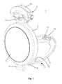
- FIG. 1 represents a simplified perspective view of a timepiece according to a preferred embodiment of the present invention
- the figure 2 represents a simplified sectional view of a first construction detail of the timepiece of the figure 1 ;
- the figure 3 represents a simplified sectional view of a second construction detail of the timepiece of the figure 1 in a first configuration
- the figure 4 represents a simplified sectional view of the second construction detail of the timepiece of the figure 1 in a second configuration
- the figure 5 represents a simplified sectional view of a third construction detail of the timepiece of the figure 1 .
- the figure 1 represents a simplified perspective view of a timepiece 1 according to a preferred embodiment of the present invention. More specifically, the timepiece 1 can be used as a wristwatch, such as a pocket watch or as a table watch.
- the timepiece 1 comprises a box 2 comprising a middle part 3, a bottom 4 and an ice cream 5.
- the bottom 4 is pivotally mounted on the middle part 3 to, on the one hand, allow the use of the timepiece as a table watch forming a support and, on the other hand, ensure the locking of the end 6 a strand of a bracelet, as further explained in more detail.
- the end 6 of the bracelet strand was represented at six o'clock on the figure 1 , that is to say in a position adjacent to a hinge 8 connecting the bottom 4 to the middle part 3.
- the caseband 3 carries a bail 9 intended to allow the attachment of a second bracelet strand (not shown) or, alternatively, a chain, of which only the end 10 is visible in the figures and which allows the use of the timepiece 1 as a pocket watch.
- the bail 9 is mounted coaxially with respect to a conventional setting ring 12.
- the box 2 has a locking member of the bottom 4 against the middle part 3 comprising in particular a tooth 13 mounted on spring and actuable by a pusher 14.
- the tooth 13 is intended to cooperate with a suitable locking surface (not visible) of the middle part.
- a finger placed in abutment against a prestressed spring in the caseband, is arranged to exert pressure on a receiving surface 15 of the bottom 4 to release it of the middle part 3 when the pusher 14 is actuated and thus facilitate the gripping of the bottom by the user.
- the figure 2 represents a simplified sectional view of a first construction detail of the timepiece of the figure 1 , more precisely of the bail 9.
- the bail 9 has two housings 20 for receiving the end 10 of the chain or, alternatively, the end of a bracelet strand similarly shaped with reference to the end 10.
- the end 10 comprises two horns 22 inserted into the housings 20 and each of which comprises a pivoting ratchet 23.
- Each side of the bail 9 carries a sleeve 24, a first hole 25 opens facing the corresponding housing 20.
- the pivots are pushed towards each other, at first, by their cooperation with inclined planes 26 formed in the bail 9.
- the pivots come opposite first holes 25 of the sockets, they deviate one from the other, under the effect of the actions of their respective springs 28, to enter the sockets and thus lock the end 10 in the bail 9.
- the sockets 24 also each carry a pusher 29 arranged projecting with respect to the outlet of its second hole 30.
- Each pusher comprises a head 32, here provided with a cabochon for illustrative purposes. limiting, carrying a rod 33 extending inside the corresponding socket.
- Three springs 35 are arranged between the head 32 of each pusher and a bearing surface 36 of the corresponding sleeve, so as to exert on the pusher a force tending to push it out of the socket.
- the bearing surface 36 has holes 37 adapted to ensure good radial retention of the corresponding spring ends.
- a retaining washer 38 is integral with the rod 33 on the side of the bearing surface 36 opposite that where the springs 35 are located, to ensure the retention of the pusher 29 in the corresponding socket.
- Each rod 33 has a length such that its end 40 is located near the pivot 23 with which it is associated when the pusher is at rest, that is to say when it is in its furthest position with reference to the corresponding socket.
- the pushers 29 when the pushers 29 are actuated by a user, against the force of the springs 35, they move towards each other and their rods 33 come into contact with the pivots 23 and push them back. also towards each other, opposing the forces of the springs 28 pivot pawls.
- the stroke of the pushers substantially corresponds to the length of the pivot portion projecting from the corresponding pawl when the latter is at rest.
- a simultaneous pressure of the user on the pushers 29 releases the end 10 to move the timepiece of a wristwatch to a pocket watch, and vice versa, or a wristwatch or pocket watch to a table watch.
- a leaf spring 42 is disposed at the end of the bail 9 to act on the end 10 and push it symmetrically when the pushers 29 are actuated.
- the figures 3 and 4 represent views in simplified cross-section, in the direction of the thickness of the box 2, of the mechanical connection between the middle part and the bottom of the timepiece of the figure 1 , especially hinge 8, in first and second respective configurations, either in an open position of the bottom and in its closed position.
- the middle part 3 has a recess 44 adjacent to the hinge 8 and intended to receive the end 6 of a bracelet strand, more precisely a stud 45 integral with the end 6.
- the pin 45 has the general shape of a cylinder in the periphery of which an annular groove 46 is formed.
- the pin 45 can be engaged in the recess when the bottom 4 is in an open position ( figure 3 ).
- a locking member 47 is mounted on the bottom, here by means of screws 48, and has a locking portion 49 of a shape substantially complementary to that of the annular groove 46.
- the locking portion 49 engages in the groove 46 and ensures the retention of the pin 45, also that of the associated bracelet strand.
- a fixed additional bottom 50 is provided to protect the inside of the box 2 when the bottom 4 is open.
- a seal disposed between the fixed bottom and the middle part ensures in particular the sealing of the corresponding assembly.
- the hinge 8 can be mounted indifferently on the middle part 3 or on the fixed base 50.
- the figure 5 represents a simplified cross-sectional view, along a plane parallel to the mean plane of the box 2, of the portion of the box comprising the hinge 8.
- the locking member 47 comprises in fact two locking portions 49 intended to cooperate with two pins 45 of a bracelet end, to improve the stability of the fastening of the bracelet to the box.
- the box 2 according to the preferred embodiment of the present invention further comprises an additional locking device of the bottom 4 arranged to lock in at least one open angular position preferential with reference to the middle part 3.
- This locking device makes it possible to define an angle between the bottom and the middle part particularly adapted to use the timepiece 1 as a table watch.
- this angle can be of the order of 60 degrees.
- This locking device comprises at least one male locking member and at least one female locking member, arranged to cooperate with each other in the preferred angular position, one being integral with the middle part and the other being solidary from the bottom.
- the locking member 47 which is integral with the bottom, carries two ball pawls 54 arranged opposite one another and constituting male locking members. Furthermore, the middle part carries a positioning element 56 having two holes 57 intended to cooperate with the ball pawls 54 to form female members of the additional locking device.
- the illustrated embodiment provides that three springs are housed in each of the pushers, but it is obvious that the skilled person can adapt the number of these springs according to his own needs, particularly in terms of necessary pressure force and dimensions of the pushers, without departing from the scope of the invention.
Landscapes
- Physics & Mathematics (AREA)
- General Physics & Mathematics (AREA)
- Buckles (AREA)
- Electric Clocks (AREA)
Abstract
Description
- La présente invention concerne une boîte pour pièce d'horlogerie, du type montre-bracelet, comportant notamment une carrure, destinée à loger un mouvement horloger, un fond et des premier et second organes d'attache à un bracelet.
- Plus précisément, la présente invention concerne un tel type de boîte pour la réalisation d'une pièce d'horlogerie dans laquelle le bracelet peut être retiré de la boîte sans nécessiter l'utilisation d'outils.
- De nombreuses pièces d'horlogerie répondant aux caractéristiques ci-dessus ont déjà été divulguées dans l'art antérieur, notamment des montres-bracelets dont la boîte présente des organes d'attache de bracelet identique de chaque côté, ceux-ci comportant éventuellement au moins un poussoir pour libérer le bracelet afin de le remplacer.
- La demande de brevet
GB 2 297 236 A - Un but principal de la présente invention est de proposer une alternative aux boîtes et pièces d'horlogerie connues de l'art antérieur, en proposant une pièce d'horlogerie qui, non seulement, peut avoir son bracelet facilement remplacé mais, en outre, peut être utilisée autrement que comme une montre-bracelet sans que cela nuise à son apparence.
- A cet effet, la présente invention concerne plus particulièrement une boîte du type mentionné plus haut, caractérisée par le fait que le premier organe d'attache est agencé pour permettre la fixation d'une chaîne pour utiliser la pièce d'horlogerie correspondante comme montre de poche, et par le fait que le fond est fixé à la carrure de manière à pouvoir pivoter, entre au moins une position ouverte et une position fermée, et définir une surface d'appui dans la position ouverte pour utiliser la pièce d'horlogerie comme montre de table.
- Grâce à ces caractéristiques, la pièce d'horlogerie peut accompagner son porteur quelle que soit son activité ou sa tenue vestimentaire.
- De manière avantageuse, le second organe d'attache comprend au moins un évidement ménagé dans la carrure, à sa périphérie et à proximité du fond, de telle manière qu'une extrémité de bracelet peut y être insérée, dans la position ouverte du fond, et verrouillée par le fond, dans la position fermée de ce dernier. Dans ce cas, le fond peut avantageusement être monté sur la carrure au moyen d'une charnière, l'évidement étant adjacent à la charnière. On peut également prévoir qu'une portion de verrouillage solidaire du fond est disposée dans l'évidement, dans la position fermée du fond, de manière à pouvoir coopérer avec l'extrémité de bracelet.
- Par ailleurs, il peut être prévu que la boîte comporte un dispositif de verrouillage du fond agencée pour le verrouiller dans au moins une position angulaire ouverte préférentielle en référence à la carrure. Un tel dispositif de verrouillage peut comporter au moins un organe de verrouillage mâle et au moins un organe de verrouillage femelle, agencés pour coopérer l'un avec l'autre dans la position angulaire préférentielle, l'un étant solidaire de la carrure et l'autre étant solidaire du fond.
- La boîte peut également comporter un organe de verrouillage supplémentaire agencé pour garantir la stabilité de la position fermée du fond contre la carrure.
- Selon un mode de réalisation préféré, la présente invention concerne également une pièce d'horlogerie comportant une boîte répondant aux caractéristiques qui précèdent ainsi qu'un ensemble comportant une telle pièce d'horlogerie, et un bracelet présentant des première et seconde extrémités adaptées pour coopérer respectivement avec les premier et second organes d'attache de la boîte, la seconde extrémité du bracelet comportant au moins un téton adapté pour être inséré à l'intérieur de l'évidement de la carrure. En outre, l'ensemble comporte avantageusement une chaîne dont une extrémité est agencée pour coopérer avec le premier organe d'attache de la pièce d'horlogerie.
- D'autres caractéristiques et avantages de la présente invention apparaîtront plus clairement à la lecture de la description détaillée d'un mode de réalisation préféré qui suit, faite en référence aux dessins annexés donnés à titre d'exemples non limitatifs et dans lesquels:
- - la
figure 1 représente une vue générale en perspective simplifiée d'une pièce d'horlogerie selon un mode de réalisation préféré de la présente invention; - - la
figure 2 représente une vue en coupe simplifiée d'un premier détail de construction de la pièce d'horlogerie de lafigure 1 ; - - la
figure 3 représente une vue en coupe simplifiée d'un second détail de construction de la pièce d'horlogerie de lafigure 1 , dans une première configuration; - - la
figure 4 représente une vue en coupe simplifiée du second détail de construction de la pièce d'horlogerie de lafigure 1 , dans une seconde configuration, et - - la
figure 5 représente une vue en coupe simplifiée d'un troisième détail de construction de la pièce d'horlogerie de lafigure 1 . - La
figure 1 représente une vue générale en perspective simplifiée d'une pièce d'horlogerie 1 selon un mode de réalisation préféré de la présente invention. Plus précisément, la pièce d'horlogerie 1 peut être utilisée comme une montre-bracelet, comme une montre de poche ou encore comme une montre de table. - A cet effet, la pièce d'horlogerie 1 comporte une boîte 2 comprenant une carrure 3, un fond 4 et une glace 5.
- Le fond 4 est monté pivotant sur la carrure 3 pour, d'une part, permettre l'utilisation de la pièce d'horlogerie comme montre de table en formant un support et, d'autre part, assurer le verrouillage de l'extrémité 6 d'un brin de bracelet, comme cela exposé plus loin plus en détail.
- A titre illustratif non limitatif, l'extrémité 6 du brin de bracelet a été représentée à six heures sur la
figure 1 , c'est-à-dire dans une position adjacente à une charnière 8 reliant le fond 4 à la carrure 3. - A l'opposé de la charnière, c'est-à-dire dans la position midi, la carrure 3 porte une bélière 9 destinée à permettre la fixation d'un second brin de bracelet (non représenté) ou, alternativement, d'une chaîne, dont seule l'extrémité 10 est visible sur les figures et qui permet l'utilisation de la pièce d'horlogerie 1 comme montre de poche.
- La bélière 9 est montée coaxiale par rapport à une couronne de mise à l'heure 12 conventionnelle.
- Il ressort également de la
figure 1 que la boîte 2 dispose d'un organe de verrouillage du fond 4 contre la carrure 3 comprenant notamment une dent 13 montée sur ressort et actionnable par un poussoir 14. La dent 13 est destinée à coopérer avec une surface de verrouillage adaptée (non visible) de la carrure. - En outre, de manière avantageuse, il est possible de prévoir qu'un doigt (non représenté), disposé en butée contre un ressort précontraint dans la carrure, est agencé pour exercer une pression sur une surface de réception 15 du fond 4 pour le dégager de la carrure 3 lorsque le poussoir 14 est actionné et faciliter ainsi la préhension du fond par l'utilisateur.
- La
figure 2 représente une vue en coupe simplifiée d'un premier détail de construction de la pièce d'horlogerie de lafigure 1 , plus précisément de la bélière 9. - La bélière 9 comporte deux logements 20 destinés à recevoir l'extrémité 10 de la chaîne ou, alternativement, l'extrémité d'un brin de bracelet conformé de manière similaire en référence à l'extrémité 10.
- L'extrémité 10 comporte deux cornes 22 insérées dans les logements 20 et dont chacune comprend un cliquet à pivot 23.
- Chaque côté de la bélière 9 porte une douille 24 dont un premier trou 25 débouche en regard du logement 20 correspondant. Lorsque l'extrémité 10 est insérée dans les logements 20, les pivots sont repoussés l'un vers l'autre, dans un premier temps, par leur coopération avec des plans inclinés 26 ménagés dans la bélière 9. Lorsque les pivots parviennent en regard des premiers trous 25 des douilles, ils s'écartent l'un de l'autre, sous l'effet des actions de leurs ressorts 28 respectifs, pour entrer dans les douilles et verrouiller ainsi l'extrémité 10 dans la bélière 9.
- Les douilles 24 portent par ailleurs chacune un poussoir 29 disposé en saillie par rapport à la sortie de son second trou 30. Chaque poussoir comprend une tête 32, munie ici d'un cabochon à titre illustratif non limitatif, portant une tige 33 s'étendant à l'intérieur de la douille correspondante.
- Trois ressorts 35 sont disposés entre la tête 32 de chaque poussoir et une surface d'appui 36 de la douille correspondante, de manière à exercer sur le poussoir une force tendant à le repousser hors de la douille. Avantageusement, la surface d'appui 36 présente des noyures 37 adaptées pour assurer un bon maintien radial des extrémités de ressort correspondantes.
- Une rondelle 38 de retenue est solidaire de la tige 33 du côté de la surface d'appui 36 opposé à celui où sont situés les ressorts 35, pour assurer la retenue du poussoir 29 dans la douille correspondante.
- Chaque tige 33 présente une longueur telle que son extrémité 40 est située à proximité du pivot 23 auquel elle est associée lorsque le poussoir est au repos, c'est-à-dire lorsqu'il est dans sa position la plus éloignée en référence à la douille correspondante.
- De ce fait, lorsque les poussoirs 29 sont actionnés par un utilisateur, à l'encontre de la force des ressorts 35, ils se déplacent l'un en direction de l'autre et leurs tiges 33 entrent au contact des pivots 23 et les repoussent également l'un vers l'autre, s'opposant aux forces des ressorts 28 des cliquets à pivot. De manière préférée, la course des poussoirs correspond sensiblement à la longueur de la portion de pivot disposée en saillie du cliquet correspondant lorsque ce dernier est au repos.
- Ainsi, une pression simultanée de l'utilisateur sur les poussoirs 29 permet de libérer l'extrémité 10 pour faire passer la pièce d'horlogerie d'une montre-bracelet à une montre de poche, et inversement, ou d'une montre-bracelet ou montre de poche à une montre de table.
- Avantageusement, un ressort lame 42 est disposé à l'extrémité de la bélière 9 pour agir sur l'extrémité 10 et la repousser avec symétrie lorsque les poussoirs 29 sont actionnés.
- Les
figures 3 et4 représentent des vues en coupe transversale simplifiée, suivant la direction de l'épaisseur de la boîte 2, de la liaison mécanique mise en oeuvre entre la carrure et le fond de la pièce d'horlogerie de lafigure 1 , notamment de la charnière 8, dans des première et seconde configurations respectives, soit dans une position ouverte du fond et dans sa position fermée. - Il ressort de ces figures que la carrure 3 présente un évidement 44 adjacent à la charnière 8 et destiné à recevoir l'extrémité 6 d'un brin de bracelet, plus précisément un téton 45 solidaire de l'extrémité 6.
- Le téton 45 présente la forme générale d'un cylindre dans la périphérie duquel une gorge annulaire 46 est ménagée.
- Le téton 45 peut être engagé dans l'évidement lorsque le fond 4 est dans une position ouverte (
figure 3 ). - Un organe de verrouillage 47 est monté sur le fond, ici par l'intermédiaire de vis 48, et présente une portion de verrouillage 49 de forme sensiblement complémentaire de celle de la gorge annulaire 46.
- Ainsi, lorsque le fond est rabattu contre la carrure dans sa position fermée (
figure 4 ), la portion de verrouillage 49 s'engage dans la gorge 46 et assure la retenue du téton 45, soit également celle du brin de bracelet associé. - On notera que dans le mode de réalisation préféré, tel qu'illustré, un fond supplémentaire fixe 50 est prévu pour protéger l'intérieur de la boîte 2 lorsque le fond 4 est ouvert. Une garniture d'étanchéité disposée entre le fond fixe et la carrure permet notamment de garantir l'étanchéité de l'assemblage correspondant. On notera également que la charnière 8 peut être montée indifféremment sur la carrure 3 ou sur le fond fixe 50.
- La
figure 5 représente une vue en coupe transversale simplifiée, suivant un plan parallèle au plan moyen de la boîte 2, de la portion de la boîte comprenant la charnière 8. - On constate que l'organe de verrouillage 47 comprend en fait deux portions de verrouillage 49 destinées à coopérer avec deux tétons 45 d'une extrémité de bracelet, afin d'améliorer la stabilité de la fixation du bracelet à la boîte.
- Par ailleurs, il ressort de la
figure 5 (et partiellement de lafigure 4 ) que la boîte 2 selon le mode de réalisation préféré de la présente invention comprend en outre un dispositif de verrouillage supplémentaire du fond 4 agencé pour le verrouiller dans au moins une position angulaire ouverte préférentielle en référence à la carrure 3. Ce dispositif de verrouillage permet de définir un angle entre le fond et la carrure particulièrement adapté pour utiliser la pièce d'horlogerie 1 comme une montre de table. De manière avantageuse, cet angle peut être de l'ordre de 60 degrés. - Ce dispositif de verrouillage comporte au moins un organe de verrouillage mâle et au moins un organe de verrouillage femelle, agencés pour coopérer l'un avec l'autre dans la position angulaire préférentielle, l'un étant solidaire de la carrure et l'autre étant solidaire du fond.
- Plus précisément, l'organe de verrouillage 47, qui est solidaire du fond, porte deux cliquets à bille 54 disposés en regard l'un de l'autre et constituant des organes de verrouillage mâle. Par ailleurs, la carrure porte un élément de positionnement 56 présentant deux trous 57 destinés à coopérer avec les cliquets à bille 54 pour constituer des organes femelle du dispositif de verrouillage supplémentaire.
- Ainsi, on a représenté sur la
figure 5 une configuration correspondant à la position ouverte préférentielle du fond 4 par rapport à la carrure 3. Dans cette configuration, les billes 58 sont agencées en saillie dans les trous 57, sous l'effet des forces exercées par les ressorts 59 auxquels elles sont associées. - Bien entendu, il est possible de prévoir une faible friction entre les deux parties de la charnière 8, en alternative ou en complément, pour assurer la stabilité de toute position ouverte du fond par rapport à la carrure. Toutefois, la mise en oeuvre d'un dispositif de verrouillage tel que décrit ci-dessus, tout en limitant autant que possible la friction entre les deux parties de la charnière, permet d'augmenter le niveau de la qualité perçue de la pièce d'horlogerie correspondante.
- La description qui précède s'attache à décrire un mode de réalisation particulier à titre d'illustration non limitative et, l'invention n'est pas limitée à la mise en oeuvre de certaines caractéristiques particulières qui viennent d'être décrites, comme par exemple les formes spécifiquement illustrées et décrites pour la boîte 2, la bélière 9, les dispositifs de verrouillage du fond, ou encore les extrémités 6 de bracelet et 10 de chaîne.
- En effet, l'homme du métier ne rencontrera pas de difficulté particulière pour adapter le contenu de la présente divulgation à ses propres besoins et mettre en oeuvre une pièce d'horlogerie dont la construction reprend les caractéristiques de l'invention sans nécessairement mettre en oeuvre, par exemple, deux tétons 45 pour assurer la retenue du bracelet dans la boîte ou encore deux cliquets à bille pour définir une position ouverte préférentielle du fond par rapport à la carrure. Bien entendu, il est possible de mettre en oeuvre un seul cliquet à bille ou tout autre dispositif équivalent permettant de définir un cran, pour définir une position préférentielle, sans sortir du cadre de la présente invention. De manière similaire, le mode de réalisation illustré à titre indicatif prévoit que trois ressorts sont logés dans chacun des poussoirs, mais il est évident que l'homme du métier pourra adapter le nombre de ces ressorts en fonction de ses propres besoins, notamment en termes de force de pression nécessaire et de dimensions des poussoirs, sans sortir du cadre de l'invention.
- On rappellera que, de manière avantageuse, le passage de toute configuration de la pièce d'horlogerie selon la présente invention à une autre configuration peut être effectué très simplement et sans nécessiter l'utilisation d'un outil.
Claims (12)
- Boîte (2) pour pièce d'horlogerie (1), du type montre-bracelet, comportant notamment une carrure (3), destinée à loger un mouvement horloger, un fond (4) et des premier et second organes d'attache (9, 8, 44, 49) à un bracelet,
caractérisée en ce que ledit premier organe d'attache (9) est agencé pour permettre également la fixation d'une chaîne pour utiliser la pièce d'horlogerie comme montre de poche, et
en ce que ledit fond (4) est relié mécaniquement à ladite carrure (3) de manière à pouvoir pivoter, entre au moins une position ouverte et une position fermée, et définir une surface d'appui dans ladite position ouverte pour utiliser la pièce d'horlogerie comme montre de table. - Boîte (2) selon la revendication 1, caractérisée en ce que ledit second organe d'attache (8, 44, 49) comprend au moins un évidement (44) ménagé dans ladite carrure (3), à sa périphérie et à proximité dudit fond (4), de telle manière qu'une extrémité (6) de bracelet peut y être insérée, dans ladite position ouverte dudit fond, et verrouillée par ledit fond, dans ladite position fermée de ce dernier.
- Boîte (2) selon la revendication 2, caractérisée en ce que ledit fond (4) est relié mécaniquement à ladite carrure (3) par l'intermédiaire d'une charnière (8), ledit évidement (44) étant adjacent à ladite charnière.
- Boîte (2) selon la revendication 2 ou 3, caractérisée en ce qu'une portion de verrouillage (49) solidaire dudit fond (4) est disposée dans ledit évidement (44), dans la position fermée dudit fond, de manière à pouvoir coopérer avec l'extrémité (6) de bracelet.
- Boîte (2) selon l'une quelconque des revendications précédentes, caractérisée en ce que ledit premier organe d'attache (9) comprend au moins un organe de commande (29) actionnable par un utilisateur pour libérer le bracelet ou la chaîne.
- Boîte (2) selon l'une quelconque des revendications précédentes, caractérisée en ce qu'elle comporte un dispositif de verrouillage (8, 54, 56, 57) dudit fond (4) agencé pour le verrouiller dans au moins une position angulaire ouverte préférentielle en référence à ladite carrure (3).
- Boîte (2) selon la revendication 6, caractérisée en ce que ledit dispositif de verrouillage (8, 54, 56, 57) comporte au moins un organe de verrouillage mâle (54) et au moins un organe de verrouillage femelle (57), agencés pour coopérer l'un avec l'autre dans ladite position angulaire préférentielle, l'un étant solidaire de ladite carrure (3) et l'autre étant solidaire dudit fond (4).
- Boîte (2) selon l'une quelconque des revendications précédentes, caractérisée en ce qu'elle comprend un organe de verrouillage supplémentaire (13, 14) agencé pour garantir la stabilité de la position fermée dudit fond (4) contre ladite carrure (3).
- Pièce d'horlogerie comportant une boîte (2) comprenant notamment une carrure (3), destinée à loger un mouvement horloger, un fond (4) et des premier et second organes d'attache (9, 8, 44, 49) à un bracelet,
caractérisée en ce que ledit premier organe d'attache (9) est agencé pour permettre la fixation d'une chaîne pour utiliser la pièce d'horlogerie comme montre de poche, et
en ce que ledit fond (4) est fixé à ladite carrure (3) de manière à pouvoir pivoter, entre au moins des positions ouverte et fermée, et définir une surface d'appui dans ladite position ouverte pour utiliser la pièce d'horlogerie comme montre de table. - Ensemble comportant
une pièce d'horlogerie selon la revendication 9, dans laquelle ledit second organe d'attache (8, 44, 49) comprend au moins un évidement (44) ménagé dans ladite carrure (3), à sa périphérie et à proximité dudit fond (4), de telle manière qu'une extrémité (6) de bracelet peut y être insérée, dans ladite position ouverte dudit fond, et verrouillée par ledit fond, dans ladite position fermée de ce dernier, et
un bracelet présentant des première et seconde extrémités (6) adaptées pour coopérer respectivement avec lesdits premier et second organes d'attache (9, 8, 44, 49),
caractérisé en ce que ladite seconde extrémité (6) du bracelet comporte au moins un téton (45) adapté pour être inséré à l'intérieur dudit évidement (44). - Ensemble selon la revendication 10, caractérisé en ce que ledit téton (45) présente une gorge périphérique (46) agencée pour coopérer avec une portion de verrouillage (49) dudit fond (4) lorsque ce dernier est dans sa position fermée.
- Ensemble selon la revendication 10 ou 11, comportant en outre une chaîne dont une extrémité (10) est agencée pour coopérer avec ledit premier organe d'attache (9) de la pièce d'horlogerie (1).
Priority Applications (6)
| Application Number | Priority Date | Filing Date | Title |
|---|---|---|---|
| EP20090172786 EP2309349B1 (fr) | 2009-10-12 | 2009-10-12 | Boîte pour pièce d'horlogerie à configurations multiples |
| HK12112168.7A HK1171523B (en) | 2009-10-12 | 2010-10-08 | Case for a timepiece having multiple configurations |
| JP2012532620A JP5550057B2 (ja) | 2009-10-12 | 2010-10-08 | 複数の構成を備えた時計用ケース |
| CN2010800448944A CN102667642B (zh) | 2009-10-12 | 2010-10-08 | 用于具有多个形态的钟表的外壳 |
| PCT/EP2010/065102 WO2011045239A1 (fr) | 2009-10-12 | 2010-10-08 | Boite pour piece d'horlogerie a configurations multiples |
| US13/444,582 US9122248B2 (en) | 2009-10-12 | 2012-04-11 | Case for timepiece with multiple configurations |
Applications Claiming Priority (1)
| Application Number | Priority Date | Filing Date | Title |
|---|---|---|---|
| EP20090172786 EP2309349B1 (fr) | 2009-10-12 | 2009-10-12 | Boîte pour pièce d'horlogerie à configurations multiples |
Publications (2)
| Publication Number | Publication Date |
|---|---|
| EP2309349A1 true EP2309349A1 (fr) | 2011-04-13 |
| EP2309349B1 EP2309349B1 (fr) | 2013-07-24 |
Family
ID=41666527
Family Applications (1)
| Application Number | Title | Priority Date | Filing Date |
|---|---|---|---|
| EP20090172786 Active EP2309349B1 (fr) | 2009-10-12 | 2009-10-12 | Boîte pour pièce d'horlogerie à configurations multiples |
Country Status (5)
| Country | Link |
|---|---|
| US (1) | US9122248B2 (fr) |
| EP (1) | EP2309349B1 (fr) |
| JP (1) | JP5550057B2 (fr) |
| CN (1) | CN102667642B (fr) |
| WO (1) | WO2011045239A1 (fr) |
Cited By (4)
| Publication number | Priority date | Publication date | Assignee | Title |
|---|---|---|---|---|
| EP3182219A1 (fr) | 2015-12-02 | 2017-06-21 | Montres Breguet S.A. | Piece d'horlogerie comprenant une boite munie d'un couvercle articule et un dispositif de verrouillage du couvercle |
| CN112099332A (zh) * | 2019-06-17 | 2020-12-18 | 奥米加股份有限公司 | 配备有至少一个盖的钟表、特别是怀表 |
| US20210286402A1 (en) * | 2020-03-13 | 2021-09-16 | Interlokit Inc. | Accessory Attachment Apparatus And Methods Related Thereto |
| USD1122137S1 (en) | 2020-03-13 | 2026-04-14 | Interlokit, Inc. | Watch band |
Families Citing this family (14)
| Publication number | Priority date | Publication date | Assignee | Title |
|---|---|---|---|---|
| CN204044523U (zh) * | 2014-02-25 | 2014-12-24 | 江世永 | 便于放置的手表 |
| FR3040219B1 (fr) | 2015-08-17 | 2019-06-28 | Claude Chouet | Montre-bracelet a changement de bracelet facilite |
| USD770931S1 (en) * | 2015-10-12 | 2016-11-08 | Vgeo, Llc | Watch bezel |
| US10895846B2 (en) | 2016-02-12 | 2021-01-19 | Pascal Raffy | Reversible wristwatch with multiple configurations |
| JP1625435S (fr) * | 2018-02-02 | 2019-02-25 | ||
| USD847004S1 (en) * | 2018-02-28 | 2019-04-30 | Citizen Watch Co., Ltd. | Watchcase |
| USD847003S1 (en) * | 2018-02-28 | 2019-04-30 | Citizen Watch Co., Ltd. | Watchcase |
| CN108508736B (zh) * | 2018-04-11 | 2019-12-06 | 歌尔科技有限公司 | 表壳和具有该表壳的腕戴设备 |
| EP3588199B1 (fr) * | 2018-06-28 | 2024-02-21 | Montres Jaquet Droz SA | Pièce d'horlogerie, notamment montre de poche, équipée d'au moins un couvercle |
| USD913119S1 (en) * | 2019-03-20 | 2021-03-16 | Citizen Watch Co., Ltd. | Watchcase |
| USD928010S1 (en) * | 2019-06-12 | 2021-08-17 | Marc Balayer | Wristwatch holder with lid and interchangeable ring |
| EP3798742B1 (fr) | 2019-09-24 | 2025-05-28 | ETA SA Manufacture Horlogère Suisse | Dispositif de connexion carrure-corne pour une montre |
| US20210240136A1 (en) * | 2020-02-05 | 2021-08-05 | Guogui ZHANG | Watch That Facilitates Replacement of Watch Core and Bezel |
| CN112806678B (zh) * | 2021-01-20 | 2023-04-07 | 维沃移动通信有限公司 | 一种手表 |
Citations (5)
| Publication number | Priority date | Publication date | Assignee | Title |
|---|---|---|---|---|
| CH203479A (fr) | 1938-03-09 | 1939-03-15 | Marvin Watch Co Fils De H A Di | Montre-bracelet. |
| DE8103059U1 (de) | 1981-02-02 | 1981-07-09 | Hilsberg, Hans Jochen, 1000 Berlin | Kleinuhr |
| GB2297236A (en) | 1995-01-30 | 1996-07-31 | Dailywin Watch Products Mfg Lt | Releasable connector for a wrist-watch or bracelet |
| US6130861A (en) * | 1997-07-31 | 2000-10-10 | Unoaerre Italia S.P.A. | Wristwatch with easily replaceable strap and with prop for standing it on a surface |
| EP1400875A1 (fr) * | 2002-09-17 | 2004-03-24 | Richemont International S.A. | Dispositif de fixation d'un bracelet sur une boíte de montre |
Family Cites Families (16)
| Publication number | Priority date | Publication date | Assignee | Title |
|---|---|---|---|---|
| US1139107A (en) * | 1915-01-09 | 1915-05-11 | Charles L Depollier | Watchcase, &c. |
| US3277646A (en) * | 1964-11-12 | 1966-10-11 | Sr Ruben M Howard | Five-in-one watch assembly |
| IT1199958B (it) * | 1985-03-05 | 1989-01-05 | Class S R L | Dispositivo articolato per l'allungamento del cinturino metallico di un orologio da polso e formante il supporto dell'orologio,dotato di fermo di sicurezza |
| JPH0421117Y2 (fr) * | 1985-11-21 | 1992-05-14 | ||
| JPH0189391U (fr) * | 1987-12-03 | 1989-06-13 | ||
| CN2098702U (zh) * | 1991-03-02 | 1992-03-11 | 李继平 | 多功能表外壳 |
| US6053631A (en) * | 1992-11-19 | 2000-04-25 | Createc Patent Holding S.A. | Plastic case with a support body for an electronic device |
| GB2309881A (en) * | 1996-02-08 | 1997-08-13 | Chung Nam Watch Co Limited | Connector for a watch and strap |
| JPH1194954A (ja) * | 1997-09-19 | 1999-04-09 | San Alpha:Kk | 多機能型携帯時計 |
| CN2414434Y (zh) * | 2000-04-20 | 2001-01-10 | 郑明智 | 随身表结构 |
| US7433275B2 (en) * | 2000-08-01 | 2008-10-07 | Hourpower Watches, Llc | Watch with hidden compartment |
| JP2002277561A (ja) * | 2001-03-19 | 2002-09-25 | Citizen Watch Co Ltd | 腕時計の使用態様変換装置 |
| CH701103B1 (fr) * | 2004-02-17 | 2010-11-30 | Lvmh Swiss Mft Sa | Boîte de montre incluant un fermoir de bracelet. |
| JP4787009B2 (ja) * | 2005-08-29 | 2011-10-05 | シチズンホールディングス株式会社 | 締結金具の構造 |
| CN201229480Y (zh) * | 2008-05-27 | 2009-04-29 | 天王电子(深圳)有限公司 | 一种表座及其使用该表座的手表 |
| IT1394429B1 (it) * | 2009-06-17 | 2012-06-15 | New Art Di Mariarosa Fantoni | Orologio da polso con cassa amovibile |
-
2009
- 2009-10-12 EP EP20090172786 patent/EP2309349B1/fr active Active
-
2010
- 2010-10-08 JP JP2012532620A patent/JP5550057B2/ja active Active
- 2010-10-08 WO PCT/EP2010/065102 patent/WO2011045239A1/fr not_active Ceased
- 2010-10-08 CN CN2010800448944A patent/CN102667642B/zh active Active
-
2012
- 2012-04-11 US US13/444,582 patent/US9122248B2/en active Active
Patent Citations (5)
| Publication number | Priority date | Publication date | Assignee | Title |
|---|---|---|---|---|
| CH203479A (fr) | 1938-03-09 | 1939-03-15 | Marvin Watch Co Fils De H A Di | Montre-bracelet. |
| DE8103059U1 (de) | 1981-02-02 | 1981-07-09 | Hilsberg, Hans Jochen, 1000 Berlin | Kleinuhr |
| GB2297236A (en) | 1995-01-30 | 1996-07-31 | Dailywin Watch Products Mfg Lt | Releasable connector for a wrist-watch or bracelet |
| US6130861A (en) * | 1997-07-31 | 2000-10-10 | Unoaerre Italia S.P.A. | Wristwatch with easily replaceable strap and with prop for standing it on a surface |
| EP1400875A1 (fr) * | 2002-09-17 | 2004-03-24 | Richemont International S.A. | Dispositif de fixation d'un bracelet sur une boíte de montre |
Cited By (8)
| Publication number | Priority date | Publication date | Assignee | Title |
|---|---|---|---|---|
| EP3182219A1 (fr) | 2015-12-02 | 2017-06-21 | Montres Breguet S.A. | Piece d'horlogerie comprenant une boite munie d'un couvercle articule et un dispositif de verrouillage du couvercle |
| CN112099332A (zh) * | 2019-06-17 | 2020-12-18 | 奥米加股份有限公司 | 配备有至少一个盖的钟表、特别是怀表 |
| CN112099332B (zh) * | 2019-06-17 | 2022-02-18 | 奥米加股份有限公司 | 配备有至少一个盖的钟表、特别是怀表 |
| US11415944B2 (en) | 2019-06-17 | 2022-08-16 | Omega Sa | Timepiece, in particular a pocket watch, equipped with at least one cover |
| US20210286402A1 (en) * | 2020-03-13 | 2021-09-16 | Interlokit Inc. | Accessory Attachment Apparatus And Methods Related Thereto |
| USD991078S1 (en) | 2020-03-13 | 2023-07-04 | Interlokit Inc. | Clasp |
| USD1119662S1 (en) | 2020-03-13 | 2026-03-24 | Interlokit Inc. | Watch band |
| USD1122137S1 (en) | 2020-03-13 | 2026-04-14 | Interlokit, Inc. | Watch band |
Also Published As
| Publication number | Publication date |
|---|---|
| WO2011045239A1 (fr) | 2011-04-21 |
| HK1171523A1 (en) | 2013-03-28 |
| EP2309349B1 (fr) | 2013-07-24 |
| JP5550057B2 (ja) | 2014-07-16 |
| US9122248B2 (en) | 2015-09-01 |
| CN102667642A (zh) | 2012-09-12 |
| CN102667642B (zh) | 2013-12-11 |
| JP2013507607A (ja) | 2013-03-04 |
| US20120257482A1 (en) | 2012-10-11 |
Similar Documents
| Publication | Publication Date | Title |
|---|---|---|
| EP2309349B1 (fr) | Boîte pour pièce d'horlogerie à configurations multiples | |
| EP3414630B1 (fr) | Montre-bracelet reversible et a configurations multiples | |
| EP1834218B1 (fr) | Montre de plongee | |
| EP3709103B1 (fr) | Dispositif de blocage de lunette tournante | |
| EP2244137A2 (fr) | Organe de commande pour pièce d'horlogerie | |
| EP3206092A1 (fr) | Montre-bracelet reversible et a configurations multiples | |
| CH701923A2 (fr) | Boite pour piece d'horlogerie a configurations multiples. | |
| EP1730605B1 (fr) | Dispositif correcteur pour piece d'horlogerie | |
| WO2011098853A1 (fr) | Boîte pour montre-bracelet | |
| CH719813B1 (fr) | Dispositif de fixation pour la fixation amovible d'un bracelet sur une boite de montre et bracelet comprenant le dispositif de fixation | |
| EP3753439B1 (fr) | Dispositif de liaison mécanique amovible entre un bracelet et une pièce mécanique | |
| CH707056B1 (fr) | Bracelet interchangeable pour pièce d'horlogerie. | |
| EP1971236B1 (fr) | Dispositif extensible pour bracelet de montre | |
| CH712115A2 (fr) | Montre-bracelet dont le bracelet peut être retiré sans outil. | |
| EP3569090A1 (fr) | Systeme d`attache d'un bracelet a une boite de montre | |
| CH713974A2 (fr) | Dispositif de liaison mécanique pour composants d'habillage horloger, notamment en forme de barrette de fixation. | |
| EP4449934A1 (fr) | Montre-bracelet | |
| CH720637A2 (fr) | Pièce d'horlogerie comportant un mécanisme de chronographe et un dispositif d'actionnement dudit mécanisme de chronographe | |
| CH712039A2 (fr) | Fermoir déployant pour bracelet. | |
| CH707307A2 (fr) | Fermoir de bracelet comportant un dispositif de réglage de la longueur utile du bracelet. | |
| WO2012175129A1 (fr) | Maillon et bracelet a maillons | |
| CH709413B1 (fr) | Pièce d'horlogerie comportant un organe de commande externe coulissant. | |
| CH719481B1 (fr) | Fermoir à boucle déployante | |
| CH718272B1 (fr) | Fermoir de bracelet avec mécanisme de mise à l'aise. | |
| CH714533B1 (fr) | Dispositif correcteur à levier de commande pour pièce d'horlogerie. |
Legal Events
| Date | Code | Title | Description |
|---|---|---|---|
| PUAI | Public reference made under article 153(3) epc to a published international application that has entered the european phase |
Free format text: ORIGINAL CODE: 0009012 |
|
| AK | Designated contracting states |
Kind code of ref document: A1 Designated state(s): AT BE BG CH CY CZ DE DK EE ES FI FR GB GR HR HU IE IS IT LI LT LU LV MC MK MT NL NO PL PT RO SE SI SK SM TR |
|
| 17P | Request for examination filed |
Effective date: 20110926 |
|
| 17Q | First examination report despatched |
Effective date: 20111024 |
|
| GRAP | Despatch of communication of intention to grant a patent |
Free format text: ORIGINAL CODE: EPIDOSNIGR1 |
|
| GRAS | Grant fee paid |
Free format text: ORIGINAL CODE: EPIDOSNIGR3 |
|
| GRAA | (expected) grant |
Free format text: ORIGINAL CODE: 0009210 |
|
| AK | Designated contracting states |
Kind code of ref document: B1 Designated state(s): AT BE BG CH CY CZ DE DK EE ES FI FR GB GR HR HU IE IS IT LI LT LU LV MC MK MT NL NO PL PT RO SE SI SK SM TR |
|
| REG | Reference to a national code |
Ref country code: GB Ref legal event code: FG4D Free format text: NOT ENGLISH |
|
| REG | Reference to a national code |
Ref country code: CH Ref legal event code: EP |
|
| REG | Reference to a national code |
Ref country code: AT Ref legal event code: REF Ref document number: 623770 Country of ref document: AT Kind code of ref document: T Effective date: 20130815 |
|
| REG | Reference to a national code |
Ref country code: IE Ref legal event code: FG4D Free format text: LANGUAGE OF EP DOCUMENT: FRENCH |
|
| REG | Reference to a national code |
Ref country code: DE Ref legal event code: R096 Ref document number: 602009017366 Country of ref document: DE Effective date: 20130919 |
|
| REG | Reference to a national code |
Ref country code: DE Ref legal event code: R082 Ref document number: 602009017366 Country of ref document: DE Representative=s name: GLAWE DELFS MOLL PARTNERSCHAFT MBB VON PATENT-, DE Ref country code: DE Ref legal event code: R082 Ref document number: 602009017366 Country of ref document: DE Representative=s name: HOESSLE PATENTANWAELTE PARTNERSCHAFT, DE |
|
| GRAT | Correction requested after decision to grant or after decision to maintain patent in amended form |
Free format text: ORIGINAL CODE: EPIDOSNCDEC |
|
| RAP2 | Party data changed (patent owner data changed or rights of a patent transferred) |
Owner name: BOVET FLEURIER SA |
|
| REG | Reference to a national code |
Ref country code: CH Ref legal event code: NV Representative=s name: E-PATENT S.A., CH |
|
| REG | Reference to a national code |
Ref country code: AT Ref legal event code: MK05 Ref document number: 623770 Country of ref document: AT Kind code of ref document: T Effective date: 20130724 |
|
| REG | Reference to a national code |
Ref country code: NL Ref legal event code: VDEP Effective date: 20130724 |
|
| REG | Reference to a national code |
Ref country code: LT Ref legal event code: MG4D |
|
| PG25 | Lapsed in a contracting state [announced via postgrant information from national office to epo] |
Ref country code: AT Free format text: LAPSE BECAUSE OF FAILURE TO SUBMIT A TRANSLATION OF THE DESCRIPTION OR TO PAY THE FEE WITHIN THE PRESCRIBED TIME-LIMIT Effective date: 20130724 Ref country code: NO Free format text: LAPSE BECAUSE OF FAILURE TO SUBMIT A TRANSLATION OF THE DESCRIPTION OR TO PAY THE FEE WITHIN THE PRESCRIBED TIME-LIMIT Effective date: 20131024 Ref country code: PT Free format text: LAPSE BECAUSE OF FAILURE TO SUBMIT A TRANSLATION OF THE DESCRIPTION OR TO PAY THE FEE WITHIN THE PRESCRIBED TIME-LIMIT Effective date: 20131125 Ref country code: SE Free format text: LAPSE BECAUSE OF FAILURE TO SUBMIT A TRANSLATION OF THE DESCRIPTION OR TO PAY THE FEE WITHIN THE PRESCRIBED TIME-LIMIT Effective date: 20130724 Ref country code: CY Free format text: LAPSE BECAUSE OF FAILURE TO SUBMIT A TRANSLATION OF THE DESCRIPTION OR TO PAY THE FEE WITHIN THE PRESCRIBED TIME-LIMIT Effective date: 20130717 Ref country code: LT Free format text: LAPSE BECAUSE OF FAILURE TO SUBMIT A TRANSLATION OF THE DESCRIPTION OR TO PAY THE FEE WITHIN THE PRESCRIBED TIME-LIMIT Effective date: 20130724 Ref country code: IS Free format text: LAPSE BECAUSE OF FAILURE TO SUBMIT A TRANSLATION OF THE DESCRIPTION OR TO PAY THE FEE WITHIN THE PRESCRIBED TIME-LIMIT Effective date: 20131124 Ref country code: HR Free format text: LAPSE BECAUSE OF FAILURE TO SUBMIT A TRANSLATION OF THE DESCRIPTION OR TO PAY THE FEE WITHIN THE PRESCRIBED TIME-LIMIT Effective date: 20130724 |
|
| PG25 | Lapsed in a contracting state [announced via postgrant information from national office to epo] |
Ref country code: PL Free format text: LAPSE BECAUSE OF FAILURE TO SUBMIT A TRANSLATION OF THE DESCRIPTION OR TO PAY THE FEE WITHIN THE PRESCRIBED TIME-LIMIT Effective date: 20130724 Ref country code: FI Free format text: LAPSE BECAUSE OF FAILURE TO SUBMIT A TRANSLATION OF THE DESCRIPTION OR TO PAY THE FEE WITHIN THE PRESCRIBED TIME-LIMIT Effective date: 20130724 Ref country code: GR Free format text: LAPSE BECAUSE OF FAILURE TO SUBMIT A TRANSLATION OF THE DESCRIPTION OR TO PAY THE FEE WITHIN THE PRESCRIBED TIME-LIMIT Effective date: 20131025 Ref country code: SI Free format text: LAPSE BECAUSE OF FAILURE TO SUBMIT A TRANSLATION OF THE DESCRIPTION OR TO PAY THE FEE WITHIN THE PRESCRIBED TIME-LIMIT Effective date: 20130724 Ref country code: LV Free format text: LAPSE BECAUSE OF FAILURE TO SUBMIT A TRANSLATION OF THE DESCRIPTION OR TO PAY THE FEE WITHIN THE PRESCRIBED TIME-LIMIT Effective date: 20130724 Ref country code: NL Free format text: LAPSE BECAUSE OF FAILURE TO SUBMIT A TRANSLATION OF THE DESCRIPTION OR TO PAY THE FEE WITHIN THE PRESCRIBED TIME-LIMIT Effective date: 20130724 |
|
| PG25 | Lapsed in a contracting state [announced via postgrant information from national office to epo] |
Ref country code: CY Free format text: LAPSE BECAUSE OF FAILURE TO SUBMIT A TRANSLATION OF THE DESCRIPTION OR TO PAY THE FEE WITHIN THE PRESCRIBED TIME-LIMIT Effective date: 20130724 |
|
| BERE | Be: lapsed |
Owner name: BOVET FLEURIER SA Effective date: 20131031 |
|
| PG25 | Lapsed in a contracting state [announced via postgrant information from national office to epo] |
Ref country code: RO Free format text: LAPSE BECAUSE OF FAILURE TO SUBMIT A TRANSLATION OF THE DESCRIPTION OR TO PAY THE FEE WITHIN THE PRESCRIBED TIME-LIMIT Effective date: 20130724 Ref country code: CZ Free format text: LAPSE BECAUSE OF FAILURE TO SUBMIT A TRANSLATION OF THE DESCRIPTION OR TO PAY THE FEE WITHIN THE PRESCRIBED TIME-LIMIT Effective date: 20130724 Ref country code: EE Free format text: LAPSE BECAUSE OF FAILURE TO SUBMIT A TRANSLATION OF THE DESCRIPTION OR TO PAY THE FEE WITHIN THE PRESCRIBED TIME-LIMIT Effective date: 20130724 Ref country code: DK Free format text: LAPSE BECAUSE OF FAILURE TO SUBMIT A TRANSLATION OF THE DESCRIPTION OR TO PAY THE FEE WITHIN THE PRESCRIBED TIME-LIMIT Effective date: 20130724 Ref country code: SK Free format text: LAPSE BECAUSE OF FAILURE TO SUBMIT A TRANSLATION OF THE DESCRIPTION OR TO PAY THE FEE WITHIN THE PRESCRIBED TIME-LIMIT Effective date: 20130724 |
|
| PG25 | Lapsed in a contracting state [announced via postgrant information from national office to epo] |
Ref country code: IT Free format text: LAPSE BECAUSE OF FAILURE TO SUBMIT A TRANSLATION OF THE DESCRIPTION OR TO PAY THE FEE WITHIN THE PRESCRIBED TIME-LIMIT Effective date: 20130724 Ref country code: MC Free format text: LAPSE BECAUSE OF FAILURE TO SUBMIT A TRANSLATION OF THE DESCRIPTION OR TO PAY THE FEE WITHIN THE PRESCRIBED TIME-LIMIT Effective date: 20130724 Ref country code: ES Free format text: LAPSE BECAUSE OF FAILURE TO SUBMIT A TRANSLATION OF THE DESCRIPTION OR TO PAY THE FEE WITHIN THE PRESCRIBED TIME-LIMIT Effective date: 20130724 |
|
| PLBE | No opposition filed within time limit |
Free format text: ORIGINAL CODE: 0009261 |
|
| STAA | Information on the status of an ep patent application or granted ep patent |
Free format text: STATUS: NO OPPOSITION FILED WITHIN TIME LIMIT |
|
| 26N | No opposition filed |
Effective date: 20140425 |
|
| REG | Reference to a national code |
Ref country code: IE Ref legal event code: MM4A |
|
| REG | Reference to a national code |
Ref country code: DE Ref legal event code: R097 Ref document number: 602009017366 Country of ref document: DE Effective date: 20140425 |
|
| PG25 | Lapsed in a contracting state [announced via postgrant information from national office to epo] |
Ref country code: BE Free format text: LAPSE BECAUSE OF NON-PAYMENT OF DUE FEES Effective date: 20131031 |
|
| PG25 | Lapsed in a contracting state [announced via postgrant information from national office to epo] |
Ref country code: IE Free format text: LAPSE BECAUSE OF NON-PAYMENT OF DUE FEES Effective date: 20131012 |
|
| PG25 | Lapsed in a contracting state [announced via postgrant information from national office to epo] |
Ref country code: SM Free format text: LAPSE BECAUSE OF FAILURE TO SUBMIT A TRANSLATION OF THE DESCRIPTION OR TO PAY THE FEE WITHIN THE PRESCRIBED TIME-LIMIT Effective date: 20130724 |
|
| PG25 | Lapsed in a contracting state [announced via postgrant information from national office to epo] |
Ref country code: HU Free format text: LAPSE BECAUSE OF FAILURE TO SUBMIT A TRANSLATION OF THE DESCRIPTION OR TO PAY THE FEE WITHIN THE PRESCRIBED TIME-LIMIT; INVALID AB INITIO Effective date: 20091012 Ref country code: BG Free format text: LAPSE BECAUSE OF FAILURE TO SUBMIT A TRANSLATION OF THE DESCRIPTION OR TO PAY THE FEE WITHIN THE PRESCRIBED TIME-LIMIT Effective date: 20130724 Ref country code: MK Free format text: LAPSE BECAUSE OF FAILURE TO SUBMIT A TRANSLATION OF THE DESCRIPTION OR TO PAY THE FEE WITHIN THE PRESCRIBED TIME-LIMIT Effective date: 20130724 Ref country code: LU Free format text: LAPSE BECAUSE OF NON-PAYMENT OF DUE FEES Effective date: 20131012 |
|
| PG25 | Lapsed in a contracting state [announced via postgrant information from national office to epo] |
Ref country code: MT Free format text: LAPSE BECAUSE OF FAILURE TO SUBMIT A TRANSLATION OF THE DESCRIPTION OR TO PAY THE FEE WITHIN THE PRESCRIBED TIME-LIMIT Effective date: 20130724 |
|
| REG | Reference to a national code |
Ref country code: FR Ref legal event code: PLFP Year of fee payment: 7 |
|
| REG | Reference to a national code |
Ref country code: FR Ref legal event code: PLFP Year of fee payment: 8 |
|
| REG | Reference to a national code |
Ref country code: DE Ref legal event code: R082 Ref document number: 602009017366 Country of ref document: DE Representative=s name: GLAWE DELFS MOLL PARTNERSCHAFT MBB VON PATENT-, DE |
|
| REG | Reference to a national code |
Ref country code: FR Ref legal event code: PLFP Year of fee payment: 9 |
|
| REG | Reference to a national code |
Ref country code: FR Ref legal event code: PLFP Year of fee payment: 10 |
|
| REG | Reference to a national code |
Ref country code: DE Ref legal event code: R082 Ref document number: 602009017366 Country of ref document: DE Representative=s name: WITTE, WELLER & PARTNER PATENTANWAELTE MBB, DE |
|
| PGFP | Annual fee paid to national office [announced via postgrant information from national office to epo] |
Ref country code: TR Payment date: 20250925 Year of fee payment: 17 |
|
| REG | Reference to a national code |
Ref country code: CH Ref legal event code: U11 Free format text: ST27 STATUS EVENT CODE: U-0-0-U10-U11 (AS PROVIDED BY THE NATIONAL OFFICE) Effective date: 20251101 |
|
| PGFP | Annual fee paid to national office [announced via postgrant information from national office to epo] |
Ref country code: DE Payment date: 20251029 Year of fee payment: 17 |
|
| PGFP | Annual fee paid to national office [announced via postgrant information from national office to epo] |
Ref country code: GB Payment date: 20251027 Year of fee payment: 17 |
|
| PGFP | Annual fee paid to national office [announced via postgrant information from national office to epo] |
Ref country code: FR Payment date: 20251027 Year of fee payment: 17 |
|
| PGFP | Annual fee paid to national office [announced via postgrant information from national office to epo] |
Ref country code: CH Payment date: 20251101 Year of fee payment: 17 |