EP2309233A2 - Dispositif de mesure de débit avec capteurs rotatifs et capteur de température - Google Patents
Dispositif de mesure de débit avec capteurs rotatifs et capteur de température Download PDFInfo
- Publication number
- EP2309233A2 EP2309233A2 EP10010470A EP10010470A EP2309233A2 EP 2309233 A2 EP2309233 A2 EP 2309233A2 EP 10010470 A EP10010470 A EP 10010470A EP 10010470 A EP10010470 A EP 10010470A EP 2309233 A2 EP2309233 A2 EP 2309233A2
- Authority
- EP
- European Patent Office
- Prior art keywords
- measuring device
- flow
- flow measuring
- sensor
- sensor carrier
- Prior art date
- Legal status (The legal status is an assumption and is not a legal conclusion. Google has not performed a legal analysis and makes no representation as to the accuracy of the status listed.)
- Withdrawn
Links
Images


Classifications
-
- G—PHYSICS
- G01—MEASURING; TESTING
- G01F—MEASURING VOLUME, VOLUME FLOW, MASS FLOW OR LIQUID LEVEL; METERING BY VOLUME
- G01F1/00—Measuring the volume flow or mass flow of fluid or fluent solid material wherein the fluid passes through a meter in a continuous flow
- G01F1/05—Measuring the volume flow or mass flow of fluid or fluent solid material wherein the fluid passes through a meter in a continuous flow by using mechanical effects
- G01F1/10—Measuring the volume flow or mass flow of fluid or fluent solid material wherein the fluid passes through a meter in a continuous flow by using mechanical effects using rotating vanes with axial admission
- G01F1/115—Measuring the volume flow or mass flow of fluid or fluent solid material wherein the fluid passes through a meter in a continuous flow by using mechanical effects using rotating vanes with axial admission with magnetic or electromagnetic coupling to the indicating device
-
- G—PHYSICS
- G01—MEASURING; TESTING
- G01F—MEASURING VOLUME, VOLUME FLOW, MASS FLOW OR LIQUID LEVEL; METERING BY VOLUME
- G01F1/00—Measuring the volume flow or mass flow of fluid or fluent solid material wherein the fluid passes through a meter in a continuous flow
- G01F1/05—Measuring the volume flow or mass flow of fluid or fluent solid material wherein the fluid passes through a meter in a continuous flow by using mechanical effects
- G01F1/10—Measuring the volume flow or mass flow of fluid or fluent solid material wherein the fluid passes through a meter in a continuous flow by using mechanical effects using rotating vanes with axial admission
- G01F1/12—Adjusting, correcting, or compensating means therefor
- G01F1/125—Adjusting, correcting, or compensating means therefor with electric, electro-mechanical or electronic means
-
- G—PHYSICS
- G01—MEASURING; TESTING
- G01F—MEASURING VOLUME, VOLUME FLOW, MASS FLOW OR LIQUID LEVEL; METERING BY VOLUME
- G01F15/00—Details of, or accessories for, apparatus of groups G01F1/00 - G01F13/00 insofar as such details or appliances are not adapted to particular types of such apparatus
- G01F15/02—Compensating or correcting for variations in pressure, density or temperature
- G01F15/022—Compensating or correcting for variations in pressure, density or temperature using electrical means
Definitions
- the present invention relates to a flow measuring device for measuring a flow of at least one liquid through a measuring chamber arranged in a housing of the flow measuring device, wherein the flow measuring device comprises at least one rotatable rotary element rotatable by the liquid passing through the measuring chamber and at least two rotary sensor for measuring the rotation of the Having rotary element.
- Generic flow measuring devices are used in a wide variety of areas. They serve to determine the flow of at least one liquid through a measuring chamber of the flow measuring device and thus through the flow measuring device. It may be a matter of determining the flow rate, the flow rate, or the quantities derived therefrom.
- the rotatable rotary element can be acted upon directly by the liquid flowing through the measuring chamber. But it is also possible that the rotary member whose rotational movement is measured by the Drehmesstrechtgru, not even arranged in the measuring chamber, but with there rotatably mounted gears, spindles or the like is in connection and is rotated by them.
- a generic flow measuring device is from the WO 2005/119185 A1 known.
- the two Drehmessreadler or sensors are spaced from each other to a housing of a measuring element element.
- Object of the present invention is to provide a compact and universally applicable arrangement of at least two Drehmesshieller for a generic flow measuring device.
- the arrangement of the two Drehmesswashler on a common sensor carrier results in a compact arrangement.
- the sensor carrier temperature sensor By additionally arranged on the sensor carrier temperature sensor, it is possible to account for temperature-related density differences - or - fluctuations of the liquid to be measured in the flow measurement or correct accordingly.
- the flow measuring device in different temperature ranges or even at changing temperatures and thus very universally applicable.
- the arrangement of the temperature sensor on the common sensor carrier in turn results in a very compact design. Due to the compact design, a correspondingly high pressure resistance can be achieved. This is especially important when the probes and the probe carrier come into direct contact with high pressure fluid. Whether there is a pressure connection between the measuring chamber and the measuring sensors or the sensor carrier depends on the respective embodiment.
- the rotary element can be acted upon directly in the measuring chamber by the liquid flowing through the measuring chamber.
- another rotatable element is present, which is connected to the rotary member and is rotated by the flowing liquid.
- the rotary element is connected to at least one measuring spindle rotatably mounted in the measuring chamber and rotatable by the liquid flowing through the measuring chamber.
- the flow rate in the form of a volume and / or the flow rate in the form of a volume per unit time and / or the direction of flow can be determined.
- also derived variables such as the mass of the liquid flowing through it can be determined. It is thus possible to use flow measuring devices according to the invention to determine various variables characterizing the flow of the fluid through the measuring chamber. For this purpose, it is favorable if the at least two rotational sensors measure the rotational speed and / or the direction of rotation of the rotary element.
- a particularly compact but also pressure-resistant construction can be achieved by arranging the rotary sensor and the temperature sensor on a common carrier plate, preferably on a common carrier board, of the sensor carrier.
- the rotary sensor are integrated into a common chip.
- a chip is understood to be an electronic component or an electronic, integrated circuit in which one or more electronic circuits are accommodated on a common substrate. Suitable chips having at least two torque sensors are known in the art. An example of this is the chip in NVE ABL 014 of the NVE Corporation, 11409 Valley View Road, Eden Prairie, MN 55344 USA.
- the sensor carrier is replaceable fastened or fixed by means of a non-destructively releasable connection means on and / or in the housing of the flow measuring device.
- a non-destructively detachable connection device is understood to mean a device which is suitable and / or intended for multiple connection and disconnection without the sensor carrier or the housing or means interconnecting the latter having to be destroyed.
- Examples of non-destructively releasable connection means are fittings, snaps and the like. These can be operated by hand but also exclusively with tools.
- Non-destructively releasable compounds are e.g. Gluing, welding, soldering and the like.
- the sensor carrier can be fastened only in a single, namely the desired or correct position on and / or in the housing of the flow measuring device
- preferred embodiments of the invention provide that the sensor carrier and / or the housing of the flow measuring device has (have) a positioning device the sensor carrier is fastened exclusively in a single end position on and / or in the housing of the flow measuring device.
- Fig. 1 shows a longitudinal section along the measuring spindle 17 through the housing 2 of the embodiment of the flow measuring device according to the invention 1.
- the measuring spindles 17 are located in the to be flowed through by the liquid measuring chamber 3 of the flow measuring device 1.
- the measuring spindles 17 are rotated.
- the number of revolutions of the measuring spindles reflects the amount of liquid that has flowed through.
- the direction of rotation of the measuring spindles 17 indicates the direction of flow of the liquid.
- the rotary member 4 is rotatably connected to one of the spindles and executed in the embodiment shown as a gear. Other embodiments of the rotary member are possible.
- the rotary element 4 is also rotated.
- the direction of rotation and number of rotations of the rotary element 4 also reflect the amount of fluid flowing through and the direction of flow.
- Such structures are in flow measuring devices according to the prior art known. It will therefore not be discussed further. The same applies to the inflow and outflow channels, which lead to the measuring chamber 3 back and away from this. These, too, can be arranged and constructed as known in the art.
- connection box 20 is arranged in the illustrated embodiment. This can on the one hand protect the terminals 23 of the sensor carrier 6. On the other hand, the terminal box can also accommodate the evaluation device or evaluation electronics for, explained in detail below, evaluation of the measured signals. In addition, the terminal box 20 can also serve to connect the terminals 23 of the sensor carrier 6 with cables leading further.
- Fig. 2 shows a view from the outside of the housing 2 according to the invention designed according to the flow measuring device according to Fig. 1 , however, the terminal box 20 is removed. You can see the rear, in the operating position away from the rotary member 4 end of the sensor support 6 with its terminals 23.
- the sensor carrier 6 is located in the illustration according to Fig. 2 in the receiving channel 11 of the housing 2 of the flow measuring device 1.
- the sensor carrier 6 can be inserted in the insertion direction 12 in the receiving channel 11 and fastened by means of the non-destructively releasable connection device 10 explained below. Randlich on the receiving channel 11 and the outer end of the groove 25 can be seen, which forms part of the groove and pin guide 14 explained below.
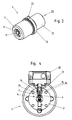
- Fig. 3 shows the sensor carrier 6 in a state in which it is removed from the receiving channel 11 and thus the housing 2 of the flow measuring device 1.
- the sensor carrier 6 has an approximately cylindrical sensor carrier housing 21. This may for example consist of metal, in particular a stainless metal such as stainless steel or have such materials.
- the annular stop 13 and the pin or pin 22 are integrally formed on this sensor carrier housing 21. Both stop 13 and pin 22 form parts of the positioning device explained in more detail below, by means of which the sensor carrier 6 can be fastened exclusively in a single end position on and / or in the housing 2 of the flow measuring device 1 is.
- the rotary member 4 facing end portion of the sensor carrier 6 of the chip 9 and immediately adjacent to the temperature sensor 7 are arranged on the sensor carrier 6.
- both Drehmesstreler 5 integrated.
- the chip 9 and the temperature sensor 7 are arranged together on the support plate 8 at the operating position of the rotary member 4 facing the end of the sensor carrier 6.
- the support plate 8 may be formed of plastic or have plastic.
- it may be a circuit board for electrical circuits. Due to the compact design shown, a high compressive strength can be achieved.
- the circuit board forming the carrier plate 8 may be a 3D circuit board which leads the conductor tracks inside the sensor carrier housing 21 back to the electrical connections 23.
- the terminals 23 are used for electrical contacting and provide the interface between a preferably arranged in the connection box 20 evaluation or their wiring and the probes 7 and 9 and 5, respectively.
- the terminals 23 are, as shown here, conveniently on, the temperature sensor 7 and the chip 9 and the Drehmesswashlind 5 opposite end of the Meßlitler mecanics 6 arranged.
- the temperature measuring sensor 7 and the chip 9 or the rotary sensor 5 are covered by a membrane. This prevents that these electronic components or the support plate 8 carrying them can be attacked by chemically aggressive liquids. It may be, for example, a thin metal membrane made of stainless steel. This can be 0.2 mm thick, for example, without disturbing the measuring process itself. If such a protective membrane is present, it conveniently covers the entire area of the chip 9 or the rotary sensor 5, the temperature sensor 7 and the support plate 8 so that no liquid can reach the sensors directly.
- Fig. 4 shows a section through the housing 2 of the measuring device 1 in the region of the mounted in the housing 2 and in the receiving channel 11 Meßputlerologis 6.
- the sectional plane shown is normal to the longitudinal extent of in Fig. 1 to be seen measuring spindle 17.
- Fig. 5 shows a part of this section Fig. 4 increased.
- the sensor carrier 6 is inserted in the insertion direction 12 in the arranged in the housing 2 receiving channel 11.
- an end position is reached when the stop 13 of the sensor carrier 6 comes to stop 28 of the housing 2 to the plant.
- the introducibility of the sensor carrier 6 is thus limited in the receiving channel 11 in the insertion direction 12.
- the distance between the integrated into the chip 9 Drehmessretelind 5 and the rotary member 4 is very simple but very accurate in the final position.
- the stop 13 as well as the counter-stop 28 thus form parts of a positioning device, which ensures that the sensor carrier 6 can be fastened exclusively in a single end position on and / or in the housing 2 of the flow measuring device 1.
- the housing 2 of the flow measuring device 1 and / or the sensor carrier 6 as part of the positioning device preferably in each case, at least one stop 13, 28, the insertion of the sensor carrier 6 in the receiving channel 11 in Insertion 12 limited.
- the groove 25 of the groove and pin guide 14 may be cut into the housing 2 of the flow measuring device 1 and the pin 22 may be fixed to the sensor carrier 6. This corresponds to the particularly good in Fig. 5 to see realized in the embodiment shown embodiment.
- a corresponding groove 25 is located in the sensor carrier 6 and the pin 22 engaging therein is fixed to the housing 2 of the flow measuring device 1.
- corresponding positioning devices are possible.
- the stops 13 and 28 may also be integrated into the groove and pin guide 14 at the same time.
- corresponding positioning devices to create at least that they allow the installation of the Meßreteleriss 6 exclusively in a single end position on and / or in the housing 2 of the flow measuring device 1, whereby incorrect assembly is avoided and after the installation of the sensor support 6, the rotary sensor 5 and the temperature sensor 7 are always accurately positioned for operation and error-free measurement.
- the connecting device 10 is provided in order to attach the sensor carrier 6 non-destructively releasably on and / or in the housing 2.
- this is a threaded sleeve which, after the sensor carrier 6 is inserted into the end position shown, is screwed into the receiving channel 11 and thus fixes the stop 13 of the sensor carrier 6 on the stop 28 of the housing 2 of the flow measuring device 1.
- a corresponding tool can be placed on the screw sleeve 10 from the side of the receiving channel 11 that is open towards the outside in order to rotate it.
- the screw sleeve 10 may have corresponding slots or the like on its end facing away from the stop 13, in which corresponding areas of the tool, not shown here, can engage. This is of course only one of many examples of how the sensor carrier 6 can be fastened non-destructively releasably by means of a connecting device 10 on and / or in the housing 2 of the flow measuring device 1.
- Fig. 5 In the sectional view shown, the seal 24 can also be seen, which prevents liquid from escaping past the sensor carrier 6 through the receiving channel 11 from the housing 2 of the flow measuring device 1.
- a magnet 15, in the present case a permanent magnet, for generating a magnetic field is arranged within the sensor carrier 6.
- the sensor carrier 6 has the magnet 15.
- the housing 2 of the flow measuring device 1 has the magnet 15.
- the magnet 15 is in any case intended to generate a magnetic field which is disturbed or changed when the rotary element 4 is rotated by it. In the illustrated embodiment are for these disorders the magnetic field, especially the teeth 26 of the rotary element 4 designed as a gear wheel responsible.
- Fig. 6 schematically shows that the magnet 15 is conveniently located on the side facing away from the probes 5 and 7 side of the rotary member 4 ,.
- the Drehmesswashler 5 and the receiving chip 9 is radially spaced from the rotary member 4 with respect to its axis of rotation 16 about which the rotary member 4 is rotatable.
- an arrangement is selected in which, as seen with respect to the axis of rotation 16, the rotary element 4 is axially or radially and axially spaced from the rotary sensors 5.
- the distance between the Drehessferlind 5 is favorably chosen so that the two Drehmesswashler 5 generate a 90 ° out of phase signal when flow-related rotation of the rotary member 4.
- a single sensor carrier 6 and arranged thereon chip 9 or Drehmesstalklind 5 and temperature sensor 7, different types of rotary elements 4 and embodiments of their teeth 26 in the axial or radial direction to measure spaced By the described positioning device is always a clear position in terms of switching distance and alignment achieved, which allows easy replacement of the probe carrier 6 together with probes 5 and 7.
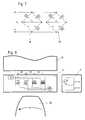
- Fig. 7 schematically shows a possible circuit of the two Drehmessratler.
- 5 Fig. 7 serves purely in the basic understanding of the circuit and does not reflect the actual physical embodiment of the rotary sensor 5 and their arrangement relative to each other.
- each of the rotary sensor 5 may have a measuring bridge circuit 18 and 19, respectively.
- the measuring bridge circuit 18 forms the first rotary sensor 5 and the measuring bridge circuit 19, the second Drehmesstalkler 5. Both are designed as Wheatstone bridges and are fed with the operating voltage U b .
- Each of the measuring bridge circuits 18 and 19 has in each case 4 interconnected resistors R1 to R4 and R5 to R8. These electrical resistors change their electrical resistance as soon as an external magnetic field applied to them changes.
- the output signals U S and U C of the two measuring bridge circuits 18 and 19 respectively reflect a magnetic field strength and / or their changes in a magnetic field measured by the respective rotary sensor.
- the output signals U S and U C are voltages tapped at the corresponding points.
- the magnet 15 generates a Magnetic field, which is disturbed or temporarily changed by the rotation of the rotary element 4 or the passage of a tooth 26 on the chip 9.
- the Drehessitler 5 and its measuring bridge circuit 18 and 19 measure this caused by the rotary member 4 change of the magnetic field and thereby generate the output signals U S and U C.
- both output signals sinusoidal.
- the frequency or period of the output signals of the U S and U C changes , but not their phase shift from each other.
- the magnitude of the phase shift between the two output signals U S and U C is determined by the spatial offset between the rotary sensors 5 and their measuring bridge circuits 18 and 19.
- this offset 27 is desirably between 0.2 and 0.8mm, more preferably between 0.4 and 0.6mm. In the embodiment shown, the offset 27 is 0.5 mm.
- Fig. 8 shows once again schematically and increases the arrangement of magnet 15, the two Drehmessreadler 5 and its measuring bridge circuit 18 and 19 receiving chip 9 and the temperature sensor 7, in relation to a guided past it tooth 26 of the rotary element 4th Fig. 8 also shows schematically how in reality the resistors A1 to A8 of the two measuring bridge circuits 18 and 19 are superposed on each other to produce the distance 27 between the rotary sensors 5 and thus the phase shift between their output signals.
- chips also referred to as GMR double sensors, are commercially available, for example, under the trade name NVE ABL 014.
- the temperature sensor 7 can, as in Fig. 8 also schematically indicated, favorably act around a three-wire resistance leader.
- the ohmic resistance of this temperature sensor changes depending on the temperature.
- This resistance can be measured in terms of U T as a function of temperature ⁇ .
- the line resistances can be taken into account via the third conductor or the voltage U L. In this way, as known per se in the prior art, a very accurate temperature measurement is possible.
- the temperature measured serves, as explained below, the temperature compensation, the calculated flow parameter, indicating the temperature dependence of the density taken into account by the liquid flowing through the measuring chamber 3 and thus a highly accurate flow measurement can be performed.
- Fig. 9a to 9c each show diagrams in which a voltage U is plotted against the time t.
- Fig. 9a shows exemplary and schematic, the output signals U S and U C of the two Drehmessrumler 5 and its measuring bridge circuit 18 and 19.
- these sinusoidal signals are converted in the embodiment shown by means of a so-called and known in the prior art Schmitt trigger into rectangular signals.
- Fig. 9b shows the time course of the generated by means of the Schmitt trigger 29 from U S square wave signal U S '.
- Fig. 9c shows the correspondingly generated from U C by means of the Schmitt trigger square wave signals U C '.
- the two in Fig. 9b and 9c shown rectangular signals are phase-shifted by 90 °.
- the Schmitt trigger in the present example uses voltage values U e and U a , which in the example shown symmetrically around the zero position of U are selected. As a result, in the illustrated embodiment, a pulse-pause ratio of 1: 1 in the square wave signals U S 'and U C ' achieved.
- the Schmitt trigger switches the voltage U S 'from zero to a predetermined value U 1 . Is subsequently after the zero crossing of the signal U S (see Fig.
- the pulses 32 and 33 thus generated each represent a defined flow rate, that is to say a defined flow volume of liquid through the measuring chamber 3.
- the total flow rate through the measuring chamber 3 during a certain time interval is obtained by summing up the number of pulses and converting by means of a calibration factor, as described in US Pat Following with reference to Fig. 10 is explained. To determine the number of pulses per unit of time, it is sufficient to use only one of the signals U S 'and U C '.
- both signals U S 'and U C ' are evaluated jointly.
- the first signal U S 'and the simultaneous consideration of the status of the second signal U C ' is, as known per se in the prior art, a determination of the direction of rotation of the rotary member 4 and thus the flow direction possible.
- Fig. 10 schematically shows a possible evaluation scheme which can be carried out by a suitable evaluation, based on the basis of Fig. 9a to 9c described procedure.
- the number Z of the pulses 32 or 33 is counted over a certain period of time. It is indicated by "+/-" in Fig. 10 , takes into account the direction of rotation by comparing the signal sequences U S 'and U C '. If the determined direction of rotation of the rotary element 4 is constant, then the pulses 32 and 33 are added up.
- the thus determined Z value thus reflects the number of pulses over a certain period of time, taking into account the direction of rotation and thus the flow direction of the liquid through the measuring chamber 3.
- the number of pulses Z thus determined is divided by a calibration factor K. This calibration factor is determined in advance in a corresponding calibration process and indicates which flow rate or which volume corresponds to a pulse 32 or 33.
- the division Z: K results in the flow rate T or the volume of liquid flowed through the measuring chamber 3 during the period during which the pulses have been counted.
- the procedure is essentially analog, but the number of pulses per unit time (Z / t) is used here as the input of the calculation.
- the flow rate ie the flow rate per unit of time
- the density of the liquid flowing through at the measured temperature or the measured temperature profile can be determined on the basis of the temperature value measured by the temperature sensor 7 in the respective time interval. For this purpose, it is possible to resort to corresponding table values, calibration curves or calculation formulas which are known in the prior art.
- the density of liquid thus determined can then be determined from the mass of liquid which has flowed through the measuring chamber 3 in this time interval through the flow rate T determined as described above. From Q 'can be calculated by the temperature-dependent determined density of the liquid, the flow mass of the liquid per unit time. If desired, flow rates or flow rates which would correspond to the volume or the volume per unit of time at a predetermined temperature can be calculated from the masses or masses per unit time calculated by means of a density at a certain predetermined temperature of the liquid. As an alternative to this procedure of temperature compensation of the measurement results, it is also possible to determine the calibration factors K as a function of the temperature. This procedure could then be used in the calculation according to Fig.
- a K value selected as a function of the temperature measured by the temperature sensor 7 is used to calculate the flow rate T or the flow rate Q '.
- the present invention allows integrated with the sensor support 6 temperature sensor 7 to take into account the influences of the temperature of the liquid on its density in the determination of flow rates or flow rates. Furthermore, the proposed system recognizes when there are reversals or changes in the direction of flow, so that this also no errors in the calculated flow rates or flow rates or derived parameters can arise.
Applications Claiming Priority (1)
| Application Number | Priority Date | Filing Date | Title |
|---|---|---|---|
| AT0159309A AT508805B1 (de) | 2009-10-09 | 2009-10-09 | Durchflussmesseinrichtung |
Publications (2)
| Publication Number | Publication Date |
|---|---|
| EP2309233A2 true EP2309233A2 (fr) | 2011-04-13 |
| EP2309233A3 EP2309233A3 (fr) | 2016-11-30 |
Family
ID=43536622
Family Applications (1)
| Application Number | Title | Priority Date | Filing Date |
|---|---|---|---|
| EP10010470.2A Withdrawn EP2309233A3 (fr) | 2009-10-09 | 2010-09-24 | Dispositif de mesure de débit avec capteurs rotatifs et capteur de température |
Country Status (3)
| Country | Link |
|---|---|
| US (1) | US20110083514A1 (fr) |
| EP (1) | EP2309233A3 (fr) |
| AT (1) | AT508805B1 (fr) |
Cited By (2)
| Publication number | Priority date | Publication date | Assignee | Title |
|---|---|---|---|---|
| DE102016002093A1 (de) | 2016-02-24 | 2017-08-24 | Kracht Gmbh | Durchflussmessvorrichtung |
| CN114370901A (zh) * | 2022-03-22 | 2022-04-19 | 四川省郫县豆瓣股份有限公司 | 一种高精度的液体流量测量探头 |
Families Citing this family (7)
| Publication number | Priority date | Publication date | Assignee | Title |
|---|---|---|---|---|
| EP2199757A1 (fr) * | 2008-12-22 | 2010-06-23 | Kral AG | Agencement doté d'au moins un débitmètre pour fluide |
| GB2480881B (en) * | 2010-06-04 | 2012-10-24 | Servomex Group Ltd | Thermal fluid flow apparatus |
| RU2596863C2 (ru) * | 2010-08-03 | 2016-09-10 | ГОУЭНС Ли | Электромагнитный расходомер |
| JP5936744B1 (ja) * | 2015-05-15 | 2016-06-22 | 三菱電機株式会社 | 流量測定装置 |
| AT517608B1 (de) * | 2016-01-21 | 2017-03-15 | Avl List Gmbh | Elektronikeinheit für ein Durchflussmessgerät |
| DE102018130793B4 (de) * | 2018-12-04 | 2024-01-25 | Endress + Hauser Flowtec Ag | Magnetisch-induktives Durchflussmessgerät |
| CN114383660A (zh) * | 2022-01-12 | 2022-04-22 | 夏罗登工业科技(上海)股份有限公司 | 一种温度流量双监测装置 |
Citations (1)
| Publication number | Priority date | Publication date | Assignee | Title |
|---|---|---|---|---|
| WO2005119185A1 (fr) | 2004-06-04 | 2005-12-15 | Vse Volumentechnik Gmbh | Capteur de debit et procede pour mesurer le volume et/ou la vitesse d'ecoulement d'un milieu |
Family Cites Families (18)
| Publication number | Priority date | Publication date | Assignee | Title |
|---|---|---|---|---|
| US4489615A (en) * | 1983-01-04 | 1984-12-25 | Breckland Meters Limited | Fluid flow meter |
| US5184519A (en) * | 1990-10-18 | 1993-02-09 | Illinois Tool Works, Inc. | High resolution flow meter |
| DE4040409C1 (fr) * | 1990-12-18 | 1992-05-14 | Vse Schweisstechnik Gmbh, 5982 Neuenrade, De | |
| DE4142062A1 (de) * | 1991-12-19 | 1993-07-01 | Salzkotten Tankanlagen | Vorrichtung zum messen von fluessigkeitsmengen in zapfsaeulen von kraftfahrzeug-tankstellen |
| US5553493A (en) * | 1994-03-02 | 1996-09-10 | Graco Inc. | High resolution flowmeter with wear detection |
| DK174370B1 (da) * | 1995-10-30 | 2003-01-13 | Salzkotten Tankanlagen | Flowmåler |
| DE29607736U1 (de) * | 1996-04-29 | 1997-08-28 | Salzkotten Tankanlagen | Vorrichtung zum Dosieren und Messen von Flüssigkeitsmengen |
| DE19703243A1 (de) * | 1997-01-29 | 1998-07-30 | Tokheim Corp | Vorrichtung zur Volumenmessung strömender Medien sowie entsprechendes Verfahren |
| JP2000023423A (ja) * | 1998-06-30 | 2000-01-21 | Ykk Corp | ブラシレスモータ用回転角検出器及びそれを用いたブラシレスモータ |
| US6244844B1 (en) * | 1999-03-31 | 2001-06-12 | Emerson Electric Co. | Fluid displacement apparatus with improved helical rotor structure |
| US6397686B1 (en) * | 1999-08-09 | 2002-06-04 | Tokheim Corporation | Hall-effect sensor placed in flowmeter to measure fuel flow rate |
| JP2002349507A (ja) * | 2001-05-31 | 2002-12-04 | Yasunaga Corp | アクチュエータ位置検出センサ及びこれを用いた油圧システム |
| US6487919B1 (en) * | 2001-11-06 | 2002-12-03 | Breed Automotive Technology, Inc. | Turbine flow monitoring device |
| DE102004027386A1 (de) * | 2004-06-04 | 2006-01-05 | Vse Volumentechnik Gmbh | Durchflussmengenfühler |
| EP1889014B1 (fr) * | 2005-06-08 | 2019-04-03 | Ecolab Inc. | Instrument de mesure a pignon ovale |
| ITTO20050415A1 (it) * | 2005-06-14 | 2006-12-15 | Eltek Spa | Dispositivo idraulico con sensore hall, sistema ed apparato utilizzatore che lo utilizza, e metodo per il suo assemblaggio |
| AR062444A1 (es) * | 2006-02-01 | 2008-11-12 | Marcelo Pividori | Dispositivo y metodo medidor de consumo de combustible para motores de combustion interna |
| FI119298B (fi) * | 2006-05-12 | 2008-09-30 | Osakeyhtioe Skf Aktiebolag | Soikiohammasratasmittari |
-
2009
- 2009-10-09 AT AT0159309A patent/AT508805B1/de not_active IP Right Cessation
-
2010
- 2010-09-24 EP EP10010470.2A patent/EP2309233A3/fr not_active Withdrawn
- 2010-10-12 US US12/902,235 patent/US20110083514A1/en not_active Abandoned
Patent Citations (1)
| Publication number | Priority date | Publication date | Assignee | Title |
|---|---|---|---|---|
| WO2005119185A1 (fr) | 2004-06-04 | 2005-12-15 | Vse Volumentechnik Gmbh | Capteur de debit et procede pour mesurer le volume et/ou la vitesse d'ecoulement d'un milieu |
Cited By (2)
| Publication number | Priority date | Publication date | Assignee | Title |
|---|---|---|---|---|
| DE102016002093A1 (de) | 2016-02-24 | 2017-08-24 | Kracht Gmbh | Durchflussmessvorrichtung |
| CN114370901A (zh) * | 2022-03-22 | 2022-04-19 | 四川省郫县豆瓣股份有限公司 | 一种高精度的液体流量测量探头 |
Also Published As
| Publication number | Publication date |
|---|---|
| EP2309233A3 (fr) | 2016-11-30 |
| US20110083514A1 (en) | 2011-04-14 |
| AT508805B1 (de) | 2011-06-15 |
| AT508805A1 (de) | 2011-04-15 |
Similar Documents
| Publication | Publication Date | Title |
|---|---|---|
| AT508805B1 (de) | Durchflussmesseinrichtung | |
| EP1751505B1 (fr) | Capteur de debit | |
| EP1850096B1 (fr) | Teletransmetteur pour appareils de mesure analogiques | |
| EP3043154A1 (fr) | Compteur de fluide | |
| DE202005021832U1 (de) | Magnetisch induktiver Durchflussmesser mit galvanischen Messelektroden | |
| DE102007027188A1 (de) | Ultraschallströmungssensor mit Quadratur-Demodulation | |
| DE102010056279A1 (de) | Vortex-Durchflussmessgerät mit optimierter Temperaturerfassung | |
| WO2016041724A1 (fr) | Procédé de fabrication d'un débitmètre à induction magnétique de section transversale réduite | |
| DE2243936A1 (de) | Ringkolbenzaehler fuer das durchlaufmessen von fluessigkeiten | |
| EP3196600B1 (fr) | Débitmètre | |
| DE102007033745B4 (de) | Induktive Drehzahlerkennung | |
| DE102020112151A1 (de) | Magnetisch-induktive Durchflussmessvorrichtung und Verfahren zum Ermitteln eines Füllstandes | |
| EP0329040A2 (fr) | Appareil pour mesurer le volume ou le débit d'un écoulement | |
| AT509725B1 (de) | Durchflussmesseinrichtung | |
| EP0952448A1 (fr) | Dispositif de retenue pour capteur de mesure des fluides de traitement | |
| DE102006036746A1 (de) | Positionsmesseinrichtung und Verfahren zur Montage einer Positionsmesseinrichtung | |
| WO2003006932A1 (fr) | Tete de mesure pour debitmetre a ultrasons | |
| EP1994375B1 (fr) | Dispositif de mesure de volume avec capteur | |
| WO2020014724A1 (fr) | Capteurs de différence de pression pour un débitmètre ainsi que débitmètre | |
| DE10214418A1 (de) | Volumenzähler zum Messen eines Flüssigkeitsvolumens | |
| WO2015082512A2 (fr) | Machine hydrodynamique pourvue d'un système de mesure | |
| DE102007054801A1 (de) | Messverfahren, Sensoranordnung und Verfahren zum Aufbau eines Messsystems | |
| DE3016985A1 (de) | Elektrischer messgroessenumformer mit einer einrichtung zur kodierung eines parameters desselben | |
| EP4260018A1 (fr) | Débitmètre coriolis modulaire | |
| EP3523603B1 (fr) | Boitier pour appareil de terrain de la technologie des mesures et de l'automatisation, permettant de surveiller et/ou de déterminer au moins une grandeur de processus d'un fluide |
Legal Events
| Date | Code | Title | Description |
|---|---|---|---|
| PUAI | Public reference made under article 153(3) epc to a published international application that has entered the european phase |
Free format text: ORIGINAL CODE: 0009012 |
|
| AK | Designated contracting states |
Kind code of ref document: A2 Designated state(s): AL AT BE BG CH CY CZ DE DK EE ES FI FR GB GR HR HU IE IS IT LI LT LU LV MC MK MT NL NO PL PT RO SE SI SK SM TR |
|
| AX | Request for extension of the european patent |
Extension state: BA ME RS |
|
| PUAL | Search report despatched |
Free format text: ORIGINAL CODE: 0009013 |
|
| AK | Designated contracting states |
Kind code of ref document: A3 Designated state(s): AL AT BE BG CH CY CZ DE DK EE ES FI FR GB GR HR HU IE IS IT LI LT LU LV MC MK MT NL NO PL PT RO SE SI SK SM TR |
|
| AX | Request for extension of the european patent |
Extension state: BA ME RS |
|
| RIC1 | Information provided on ipc code assigned before grant |
Ipc: G01F 1/115 20060101AFI20161021BHEP Ipc: G01F 15/02 20060101ALI20161021BHEP Ipc: G01F 1/12 20060101ALI20161021BHEP |
|
| STAA | Information on the status of an ep patent application or granted ep patent |
Free format text: STATUS: THE APPLICATION IS DEEMED TO BE WITHDRAWN |
|
| 18D | Application deemed to be withdrawn |
Effective date: 20170531 |