EP2309099B1 - Verbindungskanal - Google Patents
Verbindungskanal Download PDFInfo
- Publication number
- EP2309099B1 EP2309099B1 EP20090012403 EP09012403A EP2309099B1 EP 2309099 B1 EP2309099 B1 EP 2309099B1 EP 20090012403 EP20090012403 EP 20090012403 EP 09012403 A EP09012403 A EP 09012403A EP 2309099 B1 EP2309099 B1 EP 2309099B1
- Authority
- EP
- European Patent Office
- Prior art keywords
- transition duct
- skin
- surface section
- sheet
- clinch
- Prior art date
- Legal status (The legal status is an assumption and is not a legal conclusion. Google has not performed a legal analysis and makes no representation as to the accuracy of the status listed.)
- Not-in-force
Links
Images


Classifications
-
- F—MECHANICAL ENGINEERING; LIGHTING; HEATING; WEAPONS; BLASTING
- F01—MACHINES OR ENGINES IN GENERAL; ENGINE PLANTS IN GENERAL; STEAM ENGINES
- F01D—NON-POSITIVE DISPLACEMENT MACHINES OR ENGINES, e.g. STEAM TURBINES
- F01D9/00—Stators
- F01D9/02—Nozzles; Nozzle boxes; Stator blades; Guide conduits, e.g. individual nozzles
- F01D9/023—Transition ducts between combustor cans and first stage of the turbine in gas-turbine engines; their cooling or sealings
-
- F—MECHANICAL ENGINEERING; LIGHTING; HEATING; WEAPONS; BLASTING
- F05—INDEXING SCHEMES RELATING TO ENGINES OR PUMPS IN VARIOUS SUBCLASSES OF CLASSES F01-F04
- F05D—INDEXING SCHEME FOR ASPECTS RELATING TO NON-POSITIVE-DISPLACEMENT MACHINES OR ENGINES, GAS-TURBINES OR JET-PROPULSION PLANTS
- F05D2230/00—Manufacture
- F05D2230/20—Manufacture essentially without removing material
- F05D2230/23—Manufacture essentially without removing material by permanently joining parts together
- F05D2230/232—Manufacture essentially without removing material by permanently joining parts together by welding
-
- Y—GENERAL TAGGING OF NEW TECHNOLOGICAL DEVELOPMENTS; GENERAL TAGGING OF CROSS-SECTIONAL TECHNOLOGIES SPANNING OVER SEVERAL SECTIONS OF THE IPC; TECHNICAL SUBJECTS COVERED BY FORMER USPC CROSS-REFERENCE ART COLLECTIONS [XRACs] AND DIGESTS
- Y10—TECHNICAL SUBJECTS COVERED BY FORMER USPC
- Y10T—TECHNICAL SUBJECTS COVERED BY FORMER US CLASSIFICATION
- Y10T29/00—Metal working
- Y10T29/49—Method of mechanical manufacture
- Y10T29/49316—Impeller making
- Y10T29/4932—Turbomachine making
Definitions
- the invention relates to transition duct located between a combustor and a turbine section of a gas turbine. Furthermore the invention relates to a gas turbine comprising at least one transition duct and a method for manufacturing a transition duct.
- transition ducts defining fluid passages that carry hot gases from the combustors to the turbine inlet.
- the combustors are round, but the turbine inlet is annular.
- Each transition duct directs the hot gases to a section of the annular turbine inlet. Therefore, the transition duct bodies have round inlets and an exit that forms a segment of an annulus, which may substantially be close to a rectangular shape.
- a current design of a transition duct is manufactured via two opposing skins which are pressed into the basic shape and then hand worked. Butt welded joints are applied for the final mating. This is typically a manual and slow process which needs precision hand working. Besides, the used material is stiff and therefore difficult to handle during manufacturing.
- US patent US 7,047,615 B2 discloses a method of hydroforming one or more transition duct bodies between two dies in a hydroforming press. This may allow to produce transition duct bodies with no longitudinal welds.
- US patent application US 2006/0185345 A discloses a transition duct with pre-formed panels joined byseam welds.
- the present invention seeks to mitigate these drawbacks.
- a transition duct for coupling a combustor and a turbine section of a gas turbine, comprising a transition duct skin, the transition duct skin comprising a first surface section, a second surface section, and a clinch welded joint connecting the first surface section and the second surface section.
- the transition duct is designed for guiding a fluid from the inlet end of the transition duct to its outlet end.
- the joint may be formed such that the joint connects the open ends to form a closed loop to guide the fluid without leakage and substantially without turbulence from the inlet end to the outlet end of the transition duct.
- transition duct according to the invention allows a simpler manufacturing of such transition ducts, enhanced automation and less manual work.
- the transition duct skin may be formed into a shape forming an inlet end - which may be substantially circular - of the transition duct connectable to the combustor and forming an outlet end - which may be a segment of an annulus which can be considered to be substantially rectangular - of the transition duct connectable to the turbine section.
- the clinch welded joint connecting the first surface section and the second surface section may be a substantially longitudinal connection from the inlet end to the outlet end.
- “Longitudinal” is meant as parallel to the main flow direction of the fluid, substantially straight, so that only little or no turbulence is applied to the fluid that flows along the clinch welded joint or along an area where the first surface section and the section surface section meet.
- the clinch welded joint may further be defined such as the first surface section may comprise a first perpendicular surface perpendicular - i.e. substantially radially outwards - to an adjacent first part of the transition duct skin, the second surface section may comprise a second perpendicular surface perpendicular to an adjacent second part of the transition duct skin, and the clinch welded joint may join the first perpendicular surface and the second perpendicular surface.
- the first perpendicular surface and the second perpendicular surface - e.g. arranged as a projection, a flange - may be in substantially flat contact with each other.
- the transition duct skin may be of at least one sheet of metal - preferably a single sheet - pressed into a shape forming a single skin transition duct.
- single skin transition duct it is meant, that only on layer of metal forms the transition duct. If more than one sheet of metal is used, the sheets may be joined by any form of joining process, before or after the pressing into shape takes place.
- the transition duct skin being of at least one sheet of metal pressed into a shape forming a double skin transition duct.
- double skin transition duct it is meant, that a first layer of metal forms an inner fluid passage of the transition duct and a second layer of metal forms an outer surface of the transition duct. Preferably there is a gap between the first and the second layer of metal. If more than one sheet of metal is used, the sheets may be joined by any form of joining process, before or after the pressing into shape takes place. The number of sheets of metal may depend on the machines to be used to shape the metal into the required form.
- the transition duct skin may comprise a first one of the at least one sheet, a second one of the at least one sheet, and a butt welded joint connecting the first one of the at least one sheet and the second one of the at least one sheet.
- a first edge between the first perpendicular surface and the adjacent first part of the transition duct skin and an opposing second edge between the second perpendicular surface and the adjacent second part of the transition duct skin may be provided. Both the first and the second edge may be arranged such as a recess between the first edge and the second edge provides a substantially turbulence free transition of a fluid during operation of the gas turbine. The first and the second edge may preferably of 90 degree angle.
- transition duct particularly configured according to one of preceding paragraphs, the method comprising the steps of:
- a gas turbine engine 10 can generally include a compressor section 12, a combustor section 14 and a turbine section 16. A centrally disposed rotor 18 can extend through these three sections.
- the turbine section 16 can include alternating rows of vanes 20 and rotating blades 22.
- Each row of blades 22 can include a plurality of airfoils attached to a disc 24 provided on the rotor 18.
- the rotor 18 can include a plurality of axially-spaced discs 24.
- the blades 22 can extend radially outward from the discs 24.
- Each row of vanes 20 can be formed by attaching a plurality of vanes 20 to the stationary support structure in the turbine section 16.
- the vanes 20 can be mounted on a vane carrier 26 that is attached to the outer casing 28.
- the vanes 20 can extend radially inward from the vane carrier 26.
- the compressor section 12 can induct ambient air and can compress it.
- Compressed air 32 from the compressor section 12 can enter a chamber 34 enclosing the combustor section 12.
- the compressed air 32 can then be distributed to a plurality of combustors 36 (only one of which is shown).
- the compressed air 32 can be mixed with the fuel.
- the air-fuel mixture can be burned to form a hot working gas 38.
- the hot gas 38 can be routed to the turbine section 16 by a transition duct 42. As it travels through the rows of vanes 20 and blades 22, the gas 38 can expand and generate power that can drive the rotor 18.
- the expanded gas 40 can then be exhausted from the turbine 16.
- Fig. 2 shows in more detail a three-dimensional view of a number of transition ducts.
- Each of the transition ducts 42 comprises a first generally tubular main body 110 having first and second ends 102 and 104.
- the first end 102 being substantially circular, whereas the second ends 104 being a segment of an annulus and being close to a rectangular shape.
- the first end 102 is an inlet end of a transition duct 42 which will be connected to a - not shown - outlet of a combustor of a gas turbine.
- the second end 104 is an outlet end of a transition duct 42 which will be connected to a - not shown - inlet of a turbine section of a gas turbine.
- the direction of fluid through the transition duct 42 is indicated by the arrow 150.
- the fluid is guided via the main body 110 as the transition duct skin.
- Fig. 3A and 3B each schematically shows a perspective view of a transition duct 42. Again the first and second ends 102, 104 and the flow direction (arrow 150) are indicated in the figures.
- the body of the transition duct 42 is build from a transition duct skin 210, which may be a single sheet of metal which is pressed into a basic shape of the transition duct 42.
- a flange is formed as a first surface section 200.
- a further flange is formed as a second surface section 201. Both flanges, i.e. the first and second surface sections 200, 201, are then - during manufacturing - mated together via a clinch welded joint 220.
- clinch welding it is meant that the flanges get connected by punching - .i.e. clinching - the sheet of metal in the area of the first surface section 200 such that a plurality of sectors from the first surface section 200 get displaced out of their plane and get penetrated into the second surface section 201 so that the first and the second surface sections 200, 201 interlock. Additionally - in parallel or shortly afterwards to the punching step - the first and the second surface sections 200, 201 get integrally connected, e.g. via applying heat or via a cold-upsetting process - the welding step.
- a sector may preferably be of rectangular shape, but other forms may be advantageous, e.g. triangular or round.
- the clinch welded joint 220 preferably is directed outwards of the transition duct 42 so that it does not influence the fluid flow through the transition duct 42.
- the clinch welded joint 220 will end at one of the corners of the rectangular like second end 104 of a transition duct 42. With this the fluid flow within the transition duct 42 does not get affected. This effect is supported by having a totally straight clinch welded joint 220 starting from the first end 102 and ending at the second end 104 which always is parallel to the direction of the fluid flow within the transition duct 42. This is considered to be a longitudinal connection between the first surface 200 and second surface 201.
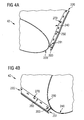
- Fig. 4A, 4B , and 4C schematically show perspective views of a clinch welded joint of a transition duct 42. Only a fraction of the transition duct 42 is depicted, seen from the upstream end of the transition duct 42, i.e. the inlet end or the first end 102.
- the clinch welded joint 220 may be perpendicular to an adjacent first part 230 of the transition duct skin and an adjacent second part 240 of the transition duct skin.
- the clinch welded joint 220 and its adjacent areas further to the end of the sheet of metal may in form of a chamfer and may have a cross section that can be considered to be in form of the shape of a "T" or a "Y" (as can be seen in Fig. 4C ).
- a first edge 260 between the first surface section 200 and the adjacent first part 230 of the transition duct skin and an opposing second edge 250 between the second surface section 201 and the adjacent second part 240 of the transition duct skin may be both of a 90 degree angle. Additionally both edges 250, 260 being may be arranged such as a recess between the first edge 260 and the second edge 250 provides a substantially turbulence free transition of a fluid during operation of the gas turbine through the transition duct 42. This is shown in the figures 4A and 4B , and specifically in Fig. 4C , by showing a totally smooth and round inner surface of the transition duct 42, even in the area of the first and second edges 260, 250. No gap or step is present at the area of the clinch welded joint 220 on the inside of the transition duct skin (this area is marked as 280 in Fig 4C ).
- Fig. 4A and 4B clinched sectors 270 are shown as rectangles.
- Fig. 4A a depression of the sectors 270 into the second surface section 201 can be seen, and in Fig. 4B an elevation from the first surface section 200.
- a single skin transition duct was shown, possibly formed from a single sheet of metal. Once brought into shape, one surface of the single sheet of metal is directed to the inside of the transition duct being in contact with the hot combustion fluid through the transition duct during operation, whereas the opposite surface of the single sheet of metal is directed to the outside of the transition duct without being in contact with the hot combustion fluid. Possibly cooling air is directed to the outside surface of the transition duct, if necessary.
- double skin a configuration is meant in which one sheet of metal defines the inner surface of the transition duct and a second sheet of metal - or the same sheet of metal but brought into shape into that position - defines the outer surface of the transition duct.
- the surfaces are spaced-apart with a small gap or channel in between the surfaces, possibly with some connections between the surfaces for stabilisation.
- a double skin configuration may be advantageous in respect of stability, weight, cooling, acoustic damping, etc.
- FIG. 5A, 5B , and 5C schematically perspective views of a clinch welded joint of a double skin transition duct 42 are shown. Only a fraction of the transition duct 42 is depicted, seen from the upstream end of the transition duct 42, i.e. the inlet end or the first end 102.
- Fig. 5A, 5B , 5C can be defined as that a clinch welded joint will be used to attach the inner skins together and a butt weld is used to attach the outer skins of the transition duct 42.
- the first surface section 200 is an area of the sheet of metal between a first rim 300 as a first edge and a second rim 301.
- Each of the rims 300 and 301 flap the sheet of metal substantially 90 degree so that two adjacent parts of the sheet of metal adjacent to the first surface section 200 are substantially parallel planes.
- rim 300 is facing to the inside of the transition duct 42 and being substantially a sharp right-angled ledge.
- figure 5C rim 301 is facing to the outside of the transition duct 42 and being substantially a section of a cylinder.
- first surface section 200 is built as a flat surface which is clinch welded via a clinch welded joint 220 with the opposing second surface section 201.
- the opposing second surface section 201 is framed similar to the first surface section 200 by a rim 302 as a first edge directed radially inwards and a second rim 303 directed radially outwards of the transition duct.
- Both the first surface section 200 and the opposing second surface section 201 are in flat contact with each other between the mentioned rims and are gapless so that no fluid streaming through the transition duct 42 during operation may leave via the mated line between rims 300 and 302.
- the transition duct skin may be of at least two sheets of metal.
- a first sheet of metal may be used to build the inner surface of the transition duct 42, the first surface section 200, and a short piece of the outside surface of the transition duct 42.
- a second sheet of metal will be formed for the outside of the double skin transition duct 42 and will be connected to the previously mentioned short piece end of the first surface. This connection may be done via butt welding as a butt welded joint 400.
- a complete double skin transition duct 42 can be built, by clinch welding the first sheet of metal to create a closed loop of sheet metal as the inner body of the transition duct 42 and by butt welding the two ends of the first sheet of metal with the second sheet of metal and therefore building a second closed surface of the transition duct 42.
- the transition duct 42 may have only one single clinch welded joint, but possibly, if assembled from a plurality of sheets of metal, also of two or a plurality of clinch welded joints.
- the transition duct 42 may be axially symmetric or point symmetric resulting in two clinch welding joints at opposing sides of the transition duct 42 or may be composed out of several segments which are clinch welded together resulting in a plurality clinch welding joints at different circumferential positions of the transition duct 42.
- the invention is also directed to a method for manufacturing such a transition duct 42.
- the method may comprise the steps of: Firstly, providing at least one sheet of metal. Secondly, forming a transition duct skin 210 from the sheet of metal, the transition duct skin 210 comprising a first surface section 200 and a second surface section 201.
- the first surface section 200 and a second surface section 201 may be formed perpendicularly in relation to adjacent parts of the sheet of metal.
Landscapes
- Engineering & Computer Science (AREA)
- Mechanical Engineering (AREA)
- General Engineering & Computer Science (AREA)
- Exhaust Silencers (AREA)
- Turbine Rotor Nozzle Sealing (AREA)
- Pressure Welding/Diffusion-Bonding (AREA)
- Rigid Pipes And Flexible Pipes (AREA)
- Laser Beam Processing (AREA)
- Structures Of Non-Positive Displacement Pumps (AREA)
Claims (10)
- Übergangskanal (42) zum Koppeln einer Brennkammer (36) und eines Turbinenabschnitts (16) einer Gasturbine (10), der eine Übergangskanalwand (210) umfasst, die einen ersten Flächenabschnitt (200), einen zweiten Flächenabschnitt (201) sowie eine Durchsetzfügeverbindung (220) umfasst, welche den ersten Flächenabschnitt (200) mit dem zweiten Flächenabschnitt (201) verbindet.
- Übergangskanal (42) nach Anspruch 1,
dadurch gekennzeichnet, dass
die Übergangskanalwand (210) so geformt ist, dass sie ein Eintrittsende (102) des Übergangskanals (42) bildet, das sich mit der Brennkammer (36) verbinden lässt, und ein Austrittsende (104) des Übergangskanals (42) bildet, das sich mit dem Turbinenabschnitt (16) verbinden lässt. - Übergangskanal (42) nach Anspruch 2,
dadurch gekennzeichnet, dass
es sich bei der Durchsetzfügeverbindung (220), die den ersten Flächenabschnitt (200) mit dem zweiten Flächenabschnitt (201) verbindet, im Wesentlichen um eine Längsverbindung vom Eintrittsende (102) zum Austrittsende (104) handelt. - Übergangskanal (42) nach einem der vorhergehenden Ansprüche,
dadurch gekennzeichnet, dass
der erste Flächenabschnitt (200) eine erste senkrechte Fläche umfasst, die senkrecht zu einem angrenzenden ersten Teil der Übergangskanalwand (210) verläuft, und der zweite Flächenabschnitt (201) eine zweite senkrechte Fläche umfasst, die senkrecht zu einem angrenzenden zweiten Teil der Übergangskanalwand (210) verläuft, und die Durchsetzfügeverbindung (220) die erste senkrechte Fläche mit der zweiten senkrechten Fläche verbindet, wobei die erste und die zweite senkrechte Fläche im Wesentlichen flach aneinander anliegen. - Übergangskanal (42) nach einem der vorhergehenden Ansprüche,
dadurch gekennzeichnet, dass
die Übergangskanalwand (210) aus mindestens einem Blech besteht, das in eine Form gepresst ist, die einen einwandigen Übergangskanal (42) bildet. - Übergangskanal (42) nach einem der Ansprüche 1 bis 4,
dadurch gekennzeichnet, dass
die Übergangskanalwand (210) aus mindestens einem Blech besteht, das in eine Form gepresst ist, die einen doppelwandigen Übergangskanal (42) bildet. - Übergangskanal (42) nach Anspruch 5 oder 6,
dadurch gekennzeichnet, dass
die Übergangskanalwand (210) ein erstes des mindestens einen Blechs, ein zweites des mindestens einen Blechs und eine Stumpfschweißverbindung (400) umfasst, welche das erste des mindestens einen Blechs mit dem zweiten des mindestens einen Blechs verbindet. - Übergangskanal (42) nach einem der Ansprüche 4 bis 7,
dadurch gekennzeichnet, dass
sowohl eine erste Kante (300) zwischen der ersten senkrechten Fläche und dem angrenzenden ersten Teil der Übergangskanalwand (210) als auch eine gegenüberliegende zweite Kante (302) zwischen der zweiten senkrechten Fläche und dem angrenzenden zweiten Teil der Übergangskanalwand (210) so angeordnet ist, dass eine Ausnehmung zwischen der ersten Kante (300) und der zweiten Kante (302) beim Betrieb der Gasturbine (10) für einen im Wesentlichen verwirbelungsfreien Übergang eines Fluids sorgt. - Gasturbine (10) mit mindestens einem Übergangskanal (42), der nach einem der vorhergehenden Ansprüche konfiguriert ist.
- Verfahren zum Herstellen eines Übergangskanals (42), der insbesondere nach einem der Ansprüche 1 bis 8 konfiguriert ist, mit folgenden Schritten:- Bilden einer Übergangskanalwand (210) mit einem ersten Flächenabschnitt (200) und einem zweiten Flächenabschnitt (201),- Durchsetzfügen einer Durchsetzfügeverbindung (220), die den ersten Flächenabschnitt (200) mit dem zweiten Flächenabschnitt (201) verbindet.
Priority Applications (5)
| Application Number | Priority Date | Filing Date | Title |
|---|---|---|---|
| EP20090012403 EP2309099B1 (de) | 2009-09-30 | 2009-09-30 | Verbindungskanal |
| US13/394,900 US8720060B2 (en) | 2009-09-30 | 2010-08-10 | Transition duct |
| PCT/EP2010/061623 WO2011038970A1 (en) | 2009-09-30 | 2010-08-10 | Transition duct |
| CN201080043974.8A CN102575525B (zh) | 2009-09-30 | 2010-08-10 | 过渡管道及其制造方法、包括过渡管道的燃气涡轮机 |
| RU2012117604/06A RU2531094C2 (ru) | 2009-09-30 | 2010-08-10 | Переходный канал газотурбинного двигателя и способ его изготовления, а также газотурбинный двигатель |
Applications Claiming Priority (1)
| Application Number | Priority Date | Filing Date | Title |
|---|---|---|---|
| EP20090012403 EP2309099B1 (de) | 2009-09-30 | 2009-09-30 | Verbindungskanal |
Publications (2)
| Publication Number | Publication Date |
|---|---|
| EP2309099A1 EP2309099A1 (de) | 2011-04-13 |
| EP2309099B1 true EP2309099B1 (de) | 2015-04-29 |
Family
ID=41665166
Family Applications (1)
| Application Number | Title | Priority Date | Filing Date |
|---|---|---|---|
| EP20090012403 Not-in-force EP2309099B1 (de) | 2009-09-30 | 2009-09-30 | Verbindungskanal |
Country Status (5)
| Country | Link |
|---|---|
| US (1) | US8720060B2 (de) |
| EP (1) | EP2309099B1 (de) |
| CN (1) | CN102575525B (de) |
| RU (1) | RU2531094C2 (de) |
| WO (1) | WO2011038970A1 (de) |
Families Citing this family (4)
| Publication number | Priority date | Publication date | Assignee | Title |
|---|---|---|---|---|
| US9784134B2 (en) * | 2013-09-25 | 2017-10-10 | Pratt & Whitney Canada Corp. | Gas turbine engine inlet assembly and method of making same |
| CN104235879A (zh) * | 2014-08-08 | 2014-12-24 | 北京华清燃气轮机与煤气化联合循环工程技术有限公司 | 燃气轮机燃烧室过渡段结构 |
| JP6345331B1 (ja) | 2017-11-20 | 2018-06-20 | 三菱日立パワーシステムズ株式会社 | ガスタービンの燃焼筒及び燃焼器並びにガスタービン |
| DE102019204544A1 (de) * | 2019-04-01 | 2020-10-01 | Siemens Aktiengesellschaft | Rohrbrennkammersystem und Gasturbinenanlage mit einem solchen Rohrbrennkammersystem |
Family Cites Families (16)
| Publication number | Priority date | Publication date | Assignee | Title |
|---|---|---|---|---|
| US3726000A (en) | 1971-05-25 | 1973-04-10 | O Hafner | Means for fastening overlying metal sheets |
| US4195474A (en) * | 1977-10-17 | 1980-04-01 | General Electric Company | Liquid-cooled transition member to turbine inlet |
| US5577313A (en) * | 1995-01-17 | 1996-11-26 | Guido; Anthony | Method and apparatus for joining deformable sheet stock |
| JPH08278029A (ja) * | 1995-02-06 | 1996-10-22 | Toshiba Corp | 燃焼器用ライナー及びその製造方法 |
| RU2120558C1 (ru) * | 1995-12-09 | 1998-10-20 | Акционерное общество "Авиадвигатель" | Камера сгорания газотурбинного двигателя |
| US5933699A (en) * | 1996-06-24 | 1999-08-03 | General Electric Company | Method of making double-walled turbine components from pre-consolidated assemblies |
| EP1247037A1 (de) | 2000-01-13 | 2002-10-09 | Manfred Arno Alfred Lupke | Metallrohr und verfahren zur dessen herstellung |
| JP3846169B2 (ja) * | 2000-09-14 | 2006-11-15 | 株式会社日立製作所 | ガスタービンの補修方法 |
| JP3831638B2 (ja) * | 2001-08-09 | 2006-10-11 | 三菱重工業株式会社 | 板状体接合方法、接合体、ガスタービン燃焼器用の尾筒、及び、ガスタービン燃焼器 |
| US7047615B2 (en) | 2002-05-06 | 2006-05-23 | Norek Richard S | Forming gas turbine transition duct bodies without longitudinal welds |
| CN2760360Y (zh) | 2004-09-16 | 2006-02-22 | 吉欣(英德)热轧不锈复合钢有限公司 | 一种冷轧连续焊接金属内复合管 |
| US7698797B2 (en) * | 2005-02-02 | 2010-04-20 | Ford Global Technologies | Apparatus and method for forming a joint between adjacent members |
| US8015818B2 (en) * | 2005-02-22 | 2011-09-13 | Siemens Energy, Inc. | Cooled transition duct for a gas turbine engine |
| MY158901A (en) * | 2008-02-20 | 2016-11-30 | General Electric Technology Gmbh | Gas turbine having an annular combustion chamber |
| US8549861B2 (en) * | 2009-01-07 | 2013-10-08 | General Electric Company | Method and apparatus to enhance transition duct cooling in a gas turbine engine |
| US20110162378A1 (en) * | 2010-01-06 | 2011-07-07 | General Electric Company | Tunable transition piece aft frame |
-
2009
- 2009-09-30 EP EP20090012403 patent/EP2309099B1/de not_active Not-in-force
-
2010
- 2010-08-10 RU RU2012117604/06A patent/RU2531094C2/ru not_active IP Right Cessation
- 2010-08-10 WO PCT/EP2010/061623 patent/WO2011038970A1/en active Application Filing
- 2010-08-10 US US13/394,900 patent/US8720060B2/en not_active Expired - Fee Related
- 2010-08-10 CN CN201080043974.8A patent/CN102575525B/zh not_active Expired - Fee Related
Also Published As
| Publication number | Publication date |
|---|---|
| RU2531094C2 (ru) | 2014-10-20 |
| RU2012117604A (ru) | 2013-11-10 |
| WO2011038970A1 (en) | 2011-04-07 |
| CN102575525B (zh) | 2016-01-20 |
| US8720060B2 (en) | 2014-05-13 |
| US20120177487A1 (en) | 2012-07-12 |
| CN102575525A (zh) | 2012-07-11 |
| EP2309099A1 (de) | 2011-04-13 |
Similar Documents
| Publication | Publication Date | Title |
|---|---|---|
| US7520055B2 (en) | Method for manufacturing a stator or rotor component | |
| US7200933B2 (en) | Method for manufacturing a stator component | |
| US7614150B2 (en) | Method for manufacturing a stator or rotor component | |
| US8225614B2 (en) | Shim for sealing transition pieces | |
| US20050246894A1 (en) | Method for manufacturing a stator or rotor component | |
| EP2187062B1 (de) | Montageverfahren für ein leitschaufelringsegment, und leitschaufelringsegment | |
| CN107109952B (zh) | 涡轮叶片、涡轮以及涡轮叶片的制造方法 | |
| EP2927430A1 (de) | Statorschaufel mit einer gekühlten plattform für ein gasturbinentriebwerk | |
| US10260362B2 (en) | Turbine vane assembly with ceramic matrix composite airfoil and friction fit metallic attachment features | |
| US20050241149A1 (en) | Method for manufacturing a stator component | |
| EP2309099B1 (de) | Verbindungskanal | |
| US20190203606A1 (en) | Systems and methods for assembling flow path components | |
| EP2613007B1 (de) | Dichtungsbaugruppe und Verfahren zur Montage einer Turbine | |
| EP2578910B1 (de) | Streifendichtungen | |
| US10450880B2 (en) | Air metering baffle assembly | |
| US20160017731A1 (en) | Vane assembly | |
| KR102519091B1 (ko) | 가스터빈의 축류 압축기 유로형상 설계방법 |
Legal Events
| Date | Code | Title | Description |
|---|---|---|---|
| PUAI | Public reference made under article 153(3) epc to a published international application that has entered the european phase |
Free format text: ORIGINAL CODE: 0009012 |
|
| AK | Designated contracting states |
Kind code of ref document: A1 Designated state(s): AT BE BG CH CY CZ DE DK EE ES FI FR GB GR HR HU IE IS IT LI LT LU LV MC MK MT NL NO PL PT RO SE SI SK SM TR |
|
| AX | Request for extension of the european patent |
Extension state: AL BA RS |
|
| 17P | Request for examination filed |
Effective date: 20110919 |
|
| RAP1 | Party data changed (applicant data changed or rights of an application transferred) |
Owner name: SIEMENS AKTIENGESELLSCHAFT |
|
| GRAP | Despatch of communication of intention to grant a patent |
Free format text: ORIGINAL CODE: EPIDOSNIGR1 |
|
| RIC1 | Information provided on ipc code assigned before grant |
Ipc: F01D 9/02 20060101AFI20141106BHEP |
|
| INTG | Intention to grant announced |
Effective date: 20141125 |
|
| INTG | Intention to grant announced |
Effective date: 20141202 |
|
| GRAS | Grant fee paid |
Free format text: ORIGINAL CODE: EPIDOSNIGR3 |
|
| GRAA | (expected) grant |
Free format text: ORIGINAL CODE: 0009210 |
|
| AK | Designated contracting states |
Kind code of ref document: B1 Designated state(s): AT BE BG CH CY CZ DE DK EE ES FI FR GB GR HR HU IE IS IT LI LT LU LV MC MK MT NL NO PL PT RO SE SI SK SM TR |
|
| REG | Reference to a national code |
Ref country code: GB Ref legal event code: FG4D |
|
| REG | Reference to a national code |
Ref country code: CH Ref legal event code: EP |
|
| REG | Reference to a national code |
Ref country code: AT Ref legal event code: REF Ref document number: 724561 Country of ref document: AT Kind code of ref document: T Effective date: 20150515 |
|
| REG | Reference to a national code |
Ref country code: IE Ref legal event code: FG4D |
|
| REG | Reference to a national code |
Ref country code: DE Ref legal event code: R096 Ref document number: 602009030906 Country of ref document: DE Effective date: 20150611 |
|
| REG | Reference to a national code |
Ref country code: NL Ref legal event code: VDEP Effective date: 20150429 |
|
| REG | Reference to a national code |
Ref country code: AT Ref legal event code: MK05 Ref document number: 724561 Country of ref document: AT Kind code of ref document: T Effective date: 20150429 |
|
| REG | Reference to a national code |
Ref country code: LT Ref legal event code: MG4D |
|
| PG25 | Lapsed in a contracting state [announced via postgrant information from national office to epo] |
Ref country code: NL Free format text: LAPSE BECAUSE OF FAILURE TO SUBMIT A TRANSLATION OF THE DESCRIPTION OR TO PAY THE FEE WITHIN THE PRESCRIBED TIME-LIMIT Effective date: 20150429 |
|
| PG25 | Lapsed in a contracting state [announced via postgrant information from national office to epo] |
Ref country code: LT Free format text: LAPSE BECAUSE OF FAILURE TO SUBMIT A TRANSLATION OF THE DESCRIPTION OR TO PAY THE FEE WITHIN THE PRESCRIBED TIME-LIMIT Effective date: 20150429 Ref country code: ES Free format text: LAPSE BECAUSE OF FAILURE TO SUBMIT A TRANSLATION OF THE DESCRIPTION OR TO PAY THE FEE WITHIN THE PRESCRIBED TIME-LIMIT Effective date: 20150429 Ref country code: NO Free format text: LAPSE BECAUSE OF FAILURE TO SUBMIT A TRANSLATION OF THE DESCRIPTION OR TO PAY THE FEE WITHIN THE PRESCRIBED TIME-LIMIT Effective date: 20150729 Ref country code: FI Free format text: LAPSE BECAUSE OF FAILURE TO SUBMIT A TRANSLATION OF THE DESCRIPTION OR TO PAY THE FEE WITHIN THE PRESCRIBED TIME-LIMIT Effective date: 20150429 Ref country code: PT Free format text: LAPSE BECAUSE OF FAILURE TO SUBMIT A TRANSLATION OF THE DESCRIPTION OR TO PAY THE FEE WITHIN THE PRESCRIBED TIME-LIMIT Effective date: 20150831 Ref country code: HR Free format text: LAPSE BECAUSE OF FAILURE TO SUBMIT A TRANSLATION OF THE DESCRIPTION OR TO PAY THE FEE WITHIN THE PRESCRIBED TIME-LIMIT Effective date: 20150429 |
|
| PG25 | Lapsed in a contracting state [announced via postgrant information from national office to epo] |
Ref country code: IS Free format text: LAPSE BECAUSE OF FAILURE TO SUBMIT A TRANSLATION OF THE DESCRIPTION OR TO PAY THE FEE WITHIN THE PRESCRIBED TIME-LIMIT Effective date: 20150829 Ref country code: GR Free format text: LAPSE BECAUSE OF FAILURE TO SUBMIT A TRANSLATION OF THE DESCRIPTION OR TO PAY THE FEE WITHIN THE PRESCRIBED TIME-LIMIT Effective date: 20150730 Ref country code: LV Free format text: LAPSE BECAUSE OF FAILURE TO SUBMIT A TRANSLATION OF THE DESCRIPTION OR TO PAY THE FEE WITHIN THE PRESCRIBED TIME-LIMIT Effective date: 20150429 Ref country code: AT Free format text: LAPSE BECAUSE OF FAILURE TO SUBMIT A TRANSLATION OF THE DESCRIPTION OR TO PAY THE FEE WITHIN THE PRESCRIBED TIME-LIMIT Effective date: 20150429 |
|
| PG25 | Lapsed in a contracting state [announced via postgrant information from national office to epo] |
Ref country code: DK Free format text: LAPSE BECAUSE OF FAILURE TO SUBMIT A TRANSLATION OF THE DESCRIPTION OR TO PAY THE FEE WITHIN THE PRESCRIBED TIME-LIMIT Effective date: 20150429 Ref country code: EE Free format text: LAPSE BECAUSE OF FAILURE TO SUBMIT A TRANSLATION OF THE DESCRIPTION OR TO PAY THE FEE WITHIN THE PRESCRIBED TIME-LIMIT Effective date: 20150429 |
|
| REG | Reference to a national code |
Ref country code: DE Ref legal event code: R097 Ref document number: 602009030906 Country of ref document: DE |
|
| PG25 | Lapsed in a contracting state [announced via postgrant information from national office to epo] |
Ref country code: RO Free format text: LAPSE BECAUSE OF NON-PAYMENT OF DUE FEES Effective date: 20150429 Ref country code: CZ Free format text: LAPSE BECAUSE OF FAILURE TO SUBMIT A TRANSLATION OF THE DESCRIPTION OR TO PAY THE FEE WITHIN THE PRESCRIBED TIME-LIMIT Effective date: 20150429 Ref country code: PL Free format text: LAPSE BECAUSE OF FAILURE TO SUBMIT A TRANSLATION OF THE DESCRIPTION OR TO PAY THE FEE WITHIN THE PRESCRIBED TIME-LIMIT Effective date: 20150429 Ref country code: SK Free format text: LAPSE BECAUSE OF FAILURE TO SUBMIT A TRANSLATION OF THE DESCRIPTION OR TO PAY THE FEE WITHIN THE PRESCRIBED TIME-LIMIT Effective date: 20150429 |
|
| PLBE | No opposition filed within time limit |
Free format text: ORIGINAL CODE: 0009261 |
|
| STAA | Information on the status of an ep patent application or granted ep patent |
Free format text: STATUS: NO OPPOSITION FILED WITHIN TIME LIMIT |
|
| 26N | No opposition filed |
Effective date: 20160201 |
|
| PG25 | Lapsed in a contracting state [announced via postgrant information from national office to epo] |
Ref country code: MC Free format text: LAPSE BECAUSE OF FAILURE TO SUBMIT A TRANSLATION OF THE DESCRIPTION OR TO PAY THE FEE WITHIN THE PRESCRIBED TIME-LIMIT Effective date: 20150429 Ref country code: LU Free format text: LAPSE BECAUSE OF FAILURE TO SUBMIT A TRANSLATION OF THE DESCRIPTION OR TO PAY THE FEE WITHIN THE PRESCRIBED TIME-LIMIT Effective date: 20150930 Ref country code: IT Free format text: LAPSE BECAUSE OF FAILURE TO SUBMIT A TRANSLATION OF THE DESCRIPTION OR TO PAY THE FEE WITHIN THE PRESCRIBED TIME-LIMIT Effective date: 20150429 |
|
| REG | Reference to a national code |
Ref country code: CH Ref legal event code: PL |
|
| PG25 | Lapsed in a contracting state [announced via postgrant information from national office to epo] |
Ref country code: SI Free format text: LAPSE BECAUSE OF FAILURE TO SUBMIT A TRANSLATION OF THE DESCRIPTION OR TO PAY THE FEE WITHIN THE PRESCRIBED TIME-LIMIT Effective date: 20150429 |
|
| REG | Reference to a national code |
Ref country code: IE Ref legal event code: MM4A |
|
| PG25 | Lapsed in a contracting state [announced via postgrant information from national office to epo] |
Ref country code: CH Free format text: LAPSE BECAUSE OF NON-PAYMENT OF DUE FEES Effective date: 20150930 Ref country code: LI Free format text: LAPSE BECAUSE OF NON-PAYMENT OF DUE FEES Effective date: 20150930 Ref country code: IE Free format text: LAPSE BECAUSE OF NON-PAYMENT OF DUE FEES Effective date: 20150930 |
|
| PG25 | Lapsed in a contracting state [announced via postgrant information from national office to epo] |
Ref country code: BE Free format text: LAPSE BECAUSE OF FAILURE TO SUBMIT A TRANSLATION OF THE DESCRIPTION OR TO PAY THE FEE WITHIN THE PRESCRIBED TIME-LIMIT Effective date: 20150429 |
|
| REG | Reference to a national code |
Ref country code: FR Ref legal event code: PLFP Year of fee payment: 8 |
|
| PG25 | Lapsed in a contracting state [announced via postgrant information from national office to epo] |
Ref country code: MT Free format text: LAPSE BECAUSE OF FAILURE TO SUBMIT A TRANSLATION OF THE DESCRIPTION OR TO PAY THE FEE WITHIN THE PRESCRIBED TIME-LIMIT Effective date: 20150429 |
|
| PG25 | Lapsed in a contracting state [announced via postgrant information from national office to epo] |
Ref country code: BG Free format text: LAPSE BECAUSE OF FAILURE TO SUBMIT A TRANSLATION OF THE DESCRIPTION OR TO PAY THE FEE WITHIN THE PRESCRIBED TIME-LIMIT Effective date: 20150429 Ref country code: HU Free format text: LAPSE BECAUSE OF FAILURE TO SUBMIT A TRANSLATION OF THE DESCRIPTION OR TO PAY THE FEE WITHIN THE PRESCRIBED TIME-LIMIT; INVALID AB INITIO Effective date: 20090930 Ref country code: SM Free format text: LAPSE BECAUSE OF FAILURE TO SUBMIT A TRANSLATION OF THE DESCRIPTION OR TO PAY THE FEE WITHIN THE PRESCRIBED TIME-LIMIT Effective date: 20150429 |
|
| PG25 | Lapsed in a contracting state [announced via postgrant information from national office to epo] |
Ref country code: CY Free format text: LAPSE BECAUSE OF FAILURE TO SUBMIT A TRANSLATION OF THE DESCRIPTION OR TO PAY THE FEE WITHIN THE PRESCRIBED TIME-LIMIT Effective date: 20150429 Ref country code: SE Free format text: LAPSE BECAUSE OF FAILURE TO SUBMIT A TRANSLATION OF THE DESCRIPTION OR TO PAY THE FEE WITHIN THE PRESCRIBED TIME-LIMIT Effective date: 20150429 |
|
| PG25 | Lapsed in a contracting state [announced via postgrant information from national office to epo] |
Ref country code: TR Free format text: LAPSE BECAUSE OF FAILURE TO SUBMIT A TRANSLATION OF THE DESCRIPTION OR TO PAY THE FEE WITHIN THE PRESCRIBED TIME-LIMIT Effective date: 20150429 |
|
| REG | Reference to a national code |
Ref country code: FR Ref legal event code: PLFP Year of fee payment: 9 |
|
| PGFP | Annual fee paid to national office [announced via postgrant information from national office to epo] |
Ref country code: GB Payment date: 20170912 Year of fee payment: 9 Ref country code: FR Payment date: 20170918 Year of fee payment: 9 |
|
| PGFP | Annual fee paid to national office [announced via postgrant information from national office to epo] |
Ref country code: DE Payment date: 20180110 Year of fee payment: 9 |
|
| PG25 | Lapsed in a contracting state [announced via postgrant information from national office to epo] |
Ref country code: MK Free format text: LAPSE BECAUSE OF FAILURE TO SUBMIT A TRANSLATION OF THE DESCRIPTION OR TO PAY THE FEE WITHIN THE PRESCRIBED TIME-LIMIT Effective date: 20150429 |
|
| REG | Reference to a national code |
Ref country code: DE Ref legal event code: R119 Ref document number: 602009030906 Country of ref document: DE |
|
| GBPC | Gb: european patent ceased through non-payment of renewal fee |
Effective date: 20180930 |
|
| PG25 | Lapsed in a contracting state [announced via postgrant information from national office to epo] |
Ref country code: DE Free format text: LAPSE BECAUSE OF NON-PAYMENT OF DUE FEES Effective date: 20190402 |
|
| PG25 | Lapsed in a contracting state [announced via postgrant information from national office to epo] |
Ref country code: FR Free format text: LAPSE BECAUSE OF NON-PAYMENT OF DUE FEES Effective date: 20180930 |
|
| PG25 | Lapsed in a contracting state [announced via postgrant information from national office to epo] |
Ref country code: GB Free format text: LAPSE BECAUSE OF NON-PAYMENT OF DUE FEES Effective date: 20180930 |