EP2305978A1 - Procédé et dispositif de régénération d'un filtre à particules agencé dans le système d'échappement d'un moteur à combustion interne - Google Patents
Procédé et dispositif de régénération d'un filtre à particules agencé dans le système d'échappement d'un moteur à combustion interne Download PDFInfo
- Publication number
- EP2305978A1 EP2305978A1 EP09012063A EP09012063A EP2305978A1 EP 2305978 A1 EP2305978 A1 EP 2305978A1 EP 09012063 A EP09012063 A EP 09012063A EP 09012063 A EP09012063 A EP 09012063A EP 2305978 A1 EP2305978 A1 EP 2305978A1
- Authority
- EP
- European Patent Office
- Prior art keywords
- exhaust gas
- particulate filter
- gas flow
- heated
- line
- Prior art date
- Legal status (The legal status is an assumption and is not a legal conclusion. Google has not performed a legal analysis and makes no representation as to the accuracy of the status listed.)
- Granted
Links
- 238000000034 method Methods 0.000 title claims abstract description 18
- 238000002485 combustion reaction Methods 0.000 title claims abstract description 15
- 230000001172 regenerating effect Effects 0.000 title abstract description 4
- 238000007254 oxidation reaction Methods 0.000 claims abstract description 63
- 230000003647 oxidation Effects 0.000 claims abstract description 60
- 238000011144 upstream manufacturing Methods 0.000 claims abstract description 38
- 238000010438 heat treatment Methods 0.000 claims abstract description 31
- 239000007789 gas Substances 0.000 claims description 112
- 239000003054 catalyst Substances 0.000 claims description 83
- 150000002430 hydrocarbons Chemical class 0.000 claims description 56
- 229930195733 hydrocarbon Natural products 0.000 claims description 53
- 230000008929 regeneration Effects 0.000 claims description 42
- 238000011069 regeneration method Methods 0.000 claims description 42
- 239000002245 particle Substances 0.000 claims description 25
- QVGXLLKOCUKJST-UHFFFAOYSA-N atomic oxygen Chemical compound [O] QVGXLLKOCUKJST-UHFFFAOYSA-N 0.000 claims description 16
- 229910052760 oxygen Inorganic materials 0.000 claims description 16
- 239000001301 oxygen Substances 0.000 claims description 16
- 230000001105 regulatory effect Effects 0.000 claims description 15
- 230000003197 catalytic effect Effects 0.000 claims description 9
- 238000006243 chemical reaction Methods 0.000 claims description 7
- 239000004215 Carbon black (E152) Substances 0.000 claims description 6
- 230000010718 Oxidation Activity Effects 0.000 claims description 5
- 230000001276 controlling effect Effects 0.000 claims description 2
- 230000001747 exhibiting effect Effects 0.000 claims 1
- 230000001590 oxidative effect Effects 0.000 claims 1
- MWUXSHHQAYIFBG-UHFFFAOYSA-N Nitric oxide Chemical compound O=[N] MWUXSHHQAYIFBG-UHFFFAOYSA-N 0.000 description 49
- 239000000446 fuel Substances 0.000 description 9
- 230000015572 biosynthetic process Effects 0.000 description 5
- BASFCYQUMIYNBI-UHFFFAOYSA-N platinum Chemical compound [Pt] BASFCYQUMIYNBI-UHFFFAOYSA-N 0.000 description 5
- 229910002091 carbon monoxide Inorganic materials 0.000 description 4
- 238000002347 injection Methods 0.000 description 4
- 239000007924 injection Substances 0.000 description 4
- 238000002156 mixing Methods 0.000 description 4
- 239000010457 zeolite Substances 0.000 description 4
- 238000010276 construction Methods 0.000 description 3
- 239000004071 soot Substances 0.000 description 3
- XEEYBQQBJWHFJM-UHFFFAOYSA-N Iron Chemical compound [Fe] XEEYBQQBJWHFJM-UHFFFAOYSA-N 0.000 description 2
- GWEVSGVZZGPLCZ-UHFFFAOYSA-N Titan oxide Chemical compound O=[Ti]=O GWEVSGVZZGPLCZ-UHFFFAOYSA-N 0.000 description 2
- GNTDGMZSJNCJKK-UHFFFAOYSA-N divanadium pentaoxide Chemical compound O=[V](=O)O[V](=O)=O GNTDGMZSJNCJKK-UHFFFAOYSA-N 0.000 description 2
- 239000007800 oxidant agent Substances 0.000 description 2
- 229910052697 platinum Inorganic materials 0.000 description 2
- 238000000926 separation method Methods 0.000 description 2
- WFKWXMTUELFFGS-UHFFFAOYSA-N tungsten Chemical compound [W] WFKWXMTUELFFGS-UHFFFAOYSA-N 0.000 description 2
- 229910052721 tungsten Inorganic materials 0.000 description 2
- 239000010937 tungsten Substances 0.000 description 2
- MGWGWNFMUOTEHG-UHFFFAOYSA-N 4-(3,5-dimethylphenyl)-1,3-thiazol-2-amine Chemical compound CC1=CC(C)=CC(C=2N=C(N)SC=2)=C1 MGWGWNFMUOTEHG-UHFFFAOYSA-N 0.000 description 1
- OYPRJOBELJOOCE-UHFFFAOYSA-N Calcium Chemical compound [Ca] OYPRJOBELJOOCE-UHFFFAOYSA-N 0.000 description 1
- OKTJSMMVPCPJKN-UHFFFAOYSA-N Carbon Chemical compound [C] OKTJSMMVPCPJKN-UHFFFAOYSA-N 0.000 description 1
- 229910052684 Cerium Inorganic materials 0.000 description 1
- RYGMFSIKBFXOCR-UHFFFAOYSA-N Copper Chemical compound [Cu] RYGMFSIKBFXOCR-UHFFFAOYSA-N 0.000 description 1
- GRYLNZFGIOXLOG-UHFFFAOYSA-N Nitric acid Chemical compound O[N+]([O-])=O GRYLNZFGIOXLOG-UHFFFAOYSA-N 0.000 description 1
- NINIDFKCEFEMDL-UHFFFAOYSA-N Sulfur Chemical compound [S] NINIDFKCEFEMDL-UHFFFAOYSA-N 0.000 description 1
- QAOWNCQODCNURD-UHFFFAOYSA-N Sulfuric acid Chemical compound OS(O)(=O)=O QAOWNCQODCNURD-UHFFFAOYSA-N 0.000 description 1
- 229910052788 barium Inorganic materials 0.000 description 1
- DSAJWYNOEDNPEQ-UHFFFAOYSA-N barium atom Chemical compound [Ba] DSAJWYNOEDNPEQ-UHFFFAOYSA-N 0.000 description 1
- 229910052791 calcium Inorganic materials 0.000 description 1
- 239000011575 calcium Substances 0.000 description 1
- 229910052799 carbon Inorganic materials 0.000 description 1
- GWXLDORMOJMVQZ-UHFFFAOYSA-N cerium Chemical compound [Ce] GWXLDORMOJMVQZ-UHFFFAOYSA-N 0.000 description 1
- 229910017052 cobalt Inorganic materials 0.000 description 1
- 239000010941 cobalt Substances 0.000 description 1
- GUTLYIVDDKVIGB-UHFFFAOYSA-N cobalt atom Chemical compound [Co] GUTLYIVDDKVIGB-UHFFFAOYSA-N 0.000 description 1
- 239000000470 constituent Substances 0.000 description 1
- 238000001816 cooling Methods 0.000 description 1
- 229910052802 copper Inorganic materials 0.000 description 1
- 239000010949 copper Substances 0.000 description 1
- 230000007797 corrosion Effects 0.000 description 1
- 238000005260 corrosion Methods 0.000 description 1
- 230000001419 dependent effect Effects 0.000 description 1
- 230000000694 effects Effects 0.000 description 1
- 239000010419 fine particle Substances 0.000 description 1
- 239000000295 fuel oil Substances 0.000 description 1
- 229910052742 iron Inorganic materials 0.000 description 1
- 239000000203 mixture Substances 0.000 description 1
- 239000010705 motor oil Substances 0.000 description 1
- 229910017604 nitric acid Inorganic materials 0.000 description 1
- JCXJVPUVTGWSNB-UHFFFAOYSA-N nitrogen dioxide Inorganic materials O=[N]=O JCXJVPUVTGWSNB-UHFFFAOYSA-N 0.000 description 1
- 239000007787 solid Substances 0.000 description 1
- 239000000243 solution Substances 0.000 description 1
- 229910001220 stainless steel Inorganic materials 0.000 description 1
- 239000010935 stainless steel Substances 0.000 description 1
- 229910052717 sulfur Inorganic materials 0.000 description 1
- 239000011593 sulfur Substances 0.000 description 1
- 239000004408 titanium dioxide Substances 0.000 description 1
- 231100000331 toxic Toxicity 0.000 description 1
- 230000002588 toxic effect Effects 0.000 description 1
- 231100000419 toxicity Toxicity 0.000 description 1
- 230000001988 toxicity Effects 0.000 description 1
- 229910052720 vanadium Inorganic materials 0.000 description 1
- LEONUFNNVUYDNQ-UHFFFAOYSA-N vanadium atom Chemical compound [V] LEONUFNNVUYDNQ-UHFFFAOYSA-N 0.000 description 1
Images

Classifications
-
- F—MECHANICAL ENGINEERING; LIGHTING; HEATING; WEAPONS; BLASTING
- F01—MACHINES OR ENGINES IN GENERAL; ENGINE PLANTS IN GENERAL; STEAM ENGINES
- F01N—GAS-FLOW SILENCERS OR EXHAUST APPARATUS FOR MACHINES OR ENGINES IN GENERAL; GAS-FLOW SILENCERS OR EXHAUST APPARATUS FOR INTERNAL COMBUSTION ENGINES
- F01N3/00—Exhaust or silencing apparatus having means for purifying, rendering innocuous, or otherwise treating exhaust
- F01N3/02—Exhaust or silencing apparatus having means for purifying, rendering innocuous, or otherwise treating exhaust for cooling, or for removing solid constituents of, exhaust
- F01N3/021—Exhaust or silencing apparatus having means for purifying, rendering innocuous, or otherwise treating exhaust for cooling, or for removing solid constituents of, exhaust by means of filters
- F01N3/023—Exhaust or silencing apparatus having means for purifying, rendering innocuous, or otherwise treating exhaust for cooling, or for removing solid constituents of, exhaust by means of filters using means for regenerating the filters, e.g. by burning trapped particles
- F01N3/025—Exhaust or silencing apparatus having means for purifying, rendering innocuous, or otherwise treating exhaust for cooling, or for removing solid constituents of, exhaust by means of filters using means for regenerating the filters, e.g. by burning trapped particles using fuel burner or by adding fuel to exhaust
- F01N3/0253—Exhaust or silencing apparatus having means for purifying, rendering innocuous, or otherwise treating exhaust for cooling, or for removing solid constituents of, exhaust by means of filters using means for regenerating the filters, e.g. by burning trapped particles using fuel burner or by adding fuel to exhaust adding fuel to exhaust gases
-
- F—MECHANICAL ENGINEERING; LIGHTING; HEATING; WEAPONS; BLASTING
- F01—MACHINES OR ENGINES IN GENERAL; ENGINE PLANTS IN GENERAL; STEAM ENGINES
- F01N—GAS-FLOW SILENCERS OR EXHAUST APPARATUS FOR MACHINES OR ENGINES IN GENERAL; GAS-FLOW SILENCERS OR EXHAUST APPARATUS FOR INTERNAL COMBUSTION ENGINES
- F01N13/00—Exhaust or silencing apparatus characterised by constructional features ; Exhaust or silencing apparatus, or parts thereof, having pertinent characteristics not provided for in, or of interest apart from, groups F01N1/00 - F01N5/00, F01N9/00, F01N11/00
- F01N13/009—Exhaust or silencing apparatus characterised by constructional features ; Exhaust or silencing apparatus, or parts thereof, having pertinent characteristics not provided for in, or of interest apart from, groups F01N1/00 - F01N5/00, F01N9/00, F01N11/00 having two or more separate purifying devices arranged in series
-
- F—MECHANICAL ENGINEERING; LIGHTING; HEATING; WEAPONS; BLASTING
- F01—MACHINES OR ENGINES IN GENERAL; ENGINE PLANTS IN GENERAL; STEAM ENGINES
- F01N—GAS-FLOW SILENCERS OR EXHAUST APPARATUS FOR MACHINES OR ENGINES IN GENERAL; GAS-FLOW SILENCERS OR EXHAUST APPARATUS FOR INTERNAL COMBUSTION ENGINES
- F01N3/00—Exhaust or silencing apparatus having means for purifying, rendering innocuous, or otherwise treating exhaust
- F01N3/02—Exhaust or silencing apparatus having means for purifying, rendering innocuous, or otherwise treating exhaust for cooling, or for removing solid constituents of, exhaust
- F01N3/021—Exhaust or silencing apparatus having means for purifying, rendering innocuous, or otherwise treating exhaust for cooling, or for removing solid constituents of, exhaust by means of filters
- F01N3/023—Exhaust or silencing apparatus having means for purifying, rendering innocuous, or otherwise treating exhaust for cooling, or for removing solid constituents of, exhaust by means of filters using means for regenerating the filters, e.g. by burning trapped particles
- F01N3/0234—Exhaust or silencing apparatus having means for purifying, rendering innocuous, or otherwise treating exhaust for cooling, or for removing solid constituents of, exhaust by means of filters using means for regenerating the filters, e.g. by burning trapped particles using heat exchange means in the exhaust line
-
- F—MECHANICAL ENGINEERING; LIGHTING; HEATING; WEAPONS; BLASTING
- F01—MACHINES OR ENGINES IN GENERAL; ENGINE PLANTS IN GENERAL; STEAM ENGINES
- F01N—GAS-FLOW SILENCERS OR EXHAUST APPARATUS FOR MACHINES OR ENGINES IN GENERAL; GAS-FLOW SILENCERS OR EXHAUST APPARATUS FOR INTERNAL COMBUSTION ENGINES
- F01N3/00—Exhaust or silencing apparatus having means for purifying, rendering innocuous, or otherwise treating exhaust
- F01N3/02—Exhaust or silencing apparatus having means for purifying, rendering innocuous, or otherwise treating exhaust for cooling, or for removing solid constituents of, exhaust
- F01N3/021—Exhaust or silencing apparatus having means for purifying, rendering innocuous, or otherwise treating exhaust for cooling, or for removing solid constituents of, exhaust by means of filters
- F01N3/023—Exhaust or silencing apparatus having means for purifying, rendering innocuous, or otherwise treating exhaust for cooling, or for removing solid constituents of, exhaust by means of filters using means for regenerating the filters, e.g. by burning trapped particles
- F01N3/0235—Exhaust or silencing apparatus having means for purifying, rendering innocuous, or otherwise treating exhaust for cooling, or for removing solid constituents of, exhaust by means of filters using means for regenerating the filters, e.g. by burning trapped particles using exhaust gas throttling means
-
- F—MECHANICAL ENGINEERING; LIGHTING; HEATING; WEAPONS; BLASTING
- F01—MACHINES OR ENGINES IN GENERAL; ENGINE PLANTS IN GENERAL; STEAM ENGINES
- F01N—GAS-FLOW SILENCERS OR EXHAUST APPARATUS FOR MACHINES OR ENGINES IN GENERAL; GAS-FLOW SILENCERS OR EXHAUST APPARATUS FOR INTERNAL COMBUSTION ENGINES
- F01N3/00—Exhaust or silencing apparatus having means for purifying, rendering innocuous, or otherwise treating exhaust
- F01N3/02—Exhaust or silencing apparatus having means for purifying, rendering innocuous, or otherwise treating exhaust for cooling, or for removing solid constituents of, exhaust
- F01N3/021—Exhaust or silencing apparatus having means for purifying, rendering innocuous, or otherwise treating exhaust for cooling, or for removing solid constituents of, exhaust by means of filters
- F01N3/033—Exhaust or silencing apparatus having means for purifying, rendering innocuous, or otherwise treating exhaust for cooling, or for removing solid constituents of, exhaust by means of filters in combination with other devices
- F01N3/035—Exhaust or silencing apparatus having means for purifying, rendering innocuous, or otherwise treating exhaust for cooling, or for removing solid constituents of, exhaust by means of filters in combination with other devices with catalytic reactors, e.g. catalysed diesel particulate filters
-
- F—MECHANICAL ENGINEERING; LIGHTING; HEATING; WEAPONS; BLASTING
- F01—MACHINES OR ENGINES IN GENERAL; ENGINE PLANTS IN GENERAL; STEAM ENGINES
- F01N—GAS-FLOW SILENCERS OR EXHAUST APPARATUS FOR MACHINES OR ENGINES IN GENERAL; GAS-FLOW SILENCERS OR EXHAUST APPARATUS FOR INTERNAL COMBUSTION ENGINES
- F01N3/00—Exhaust or silencing apparatus having means for purifying, rendering innocuous, or otherwise treating exhaust
- F01N3/08—Exhaust or silencing apparatus having means for purifying, rendering innocuous, or otherwise treating exhaust for rendering innocuous
- F01N3/10—Exhaust or silencing apparatus having means for purifying, rendering innocuous, or otherwise treating exhaust for rendering innocuous by thermal or catalytic conversion of noxious components of exhaust
- F01N3/18—Exhaust or silencing apparatus having means for purifying, rendering innocuous, or otherwise treating exhaust for rendering innocuous by thermal or catalytic conversion of noxious components of exhaust characterised by methods of operation; Control
- F01N3/20—Exhaust or silencing apparatus having means for purifying, rendering innocuous, or otherwise treating exhaust for rendering innocuous by thermal or catalytic conversion of noxious components of exhaust characterised by methods of operation; Control specially adapted for catalytic conversion ; Methods of operation or control of catalytic converters
- F01N3/2053—By-passing catalytic reactors, e.g. to prevent overheating
-
- F—MECHANICAL ENGINEERING; LIGHTING; HEATING; WEAPONS; BLASTING
- F01—MACHINES OR ENGINES IN GENERAL; ENGINE PLANTS IN GENERAL; STEAM ENGINES
- F01N—GAS-FLOW SILENCERS OR EXHAUST APPARATUS FOR MACHINES OR ENGINES IN GENERAL; GAS-FLOW SILENCERS OR EXHAUST APPARATUS FOR INTERNAL COMBUSTION ENGINES
- F01N9/00—Electrical control of exhaust gas treating apparatus
- F01N9/002—Electrical control of exhaust gas treating apparatus of filter regeneration, e.g. detection of clogging
-
- F—MECHANICAL ENGINEERING; LIGHTING; HEATING; WEAPONS; BLASTING
- F01—MACHINES OR ENGINES IN GENERAL; ENGINE PLANTS IN GENERAL; STEAM ENGINES
- F01N—GAS-FLOW SILENCERS OR EXHAUST APPARATUS FOR MACHINES OR ENGINES IN GENERAL; GAS-FLOW SILENCERS OR EXHAUST APPARATUS FOR INTERNAL COMBUSTION ENGINES
- F01N2410/00—By-passing, at least partially, exhaust from inlet to outlet of apparatus, to atmosphere or to other device
- F01N2410/03—By-passing, at least partially, exhaust from inlet to outlet of apparatus, to atmosphere or to other device in case of low temperature
-
- F—MECHANICAL ENGINEERING; LIGHTING; HEATING; WEAPONS; BLASTING
- F01—MACHINES OR ENGINES IN GENERAL; ENGINE PLANTS IN GENERAL; STEAM ENGINES
- F01N—GAS-FLOW SILENCERS OR EXHAUST APPARATUS FOR MACHINES OR ENGINES IN GENERAL; GAS-FLOW SILENCERS OR EXHAUST APPARATUS FOR INTERNAL COMBUSTION ENGINES
- F01N2410/00—By-passing, at least partially, exhaust from inlet to outlet of apparatus, to atmosphere or to other device
- F01N2410/04—By-passing, at least partially, exhaust from inlet to outlet of apparatus, to atmosphere or to other device during regeneration period, e.g. of particle filter
-
- Y—GENERAL TAGGING OF NEW TECHNOLOGICAL DEVELOPMENTS; GENERAL TAGGING OF CROSS-SECTIONAL TECHNOLOGIES SPANNING OVER SEVERAL SECTIONS OF THE IPC; TECHNICAL SUBJECTS COVERED BY FORMER USPC CROSS-REFERENCE ART COLLECTIONS [XRACs] AND DIGESTS
- Y02—TECHNOLOGIES OR APPLICATIONS FOR MITIGATION OR ADAPTATION AGAINST CLIMATE CHANGE
- Y02T—CLIMATE CHANGE MITIGATION TECHNOLOGIES RELATED TO TRANSPORTATION
- Y02T10/00—Road transport of goods or passengers
- Y02T10/10—Internal combustion engine [ICE] based vehicles
- Y02T10/40—Engine management systems
Definitions
- the invention relates to a method for regeneration of a particle filter arranged in the exhaust line of an internal combustion engine according to the preamble of claim 1 and to a device for regeneration of a particle filter arranged in the exhaust line of an internal combustion engine according to the preamble of claim 8.
- the invention relates to a method and apparatus for regeneration of particulate filters in super-powered internal combustion engines, such as diesel engines or direct-injection gasoline engines, such as those found in commercial vehicles or motor vehicles.
- particle separators or particle filters are used regularly in vehicles.
- a P microwave filter arrangement in vehicles is for example from the EP 10 727 65 A2 known.
- particle separators differ from the particle filters in that the exhaust gas flow is guided along the separation structures while in particulate filters, the exhaust gas must flow through the filter medium.
- particulate filters tend to clog, which increases the exhaust backpressure, that is, causes an undesirable pressure increase at the exhaust port of an internal combustion engine, which in turn reduces engine performance and results in increased fuel consumption of the engine.
- An example of such a particle filter arrangement is from the EP 03 418 32 A2 known.
- an oxidation catalyst arranged upstream of the particle separator or of the particle filter oxidizes the nitrogen monoxide (NO) in the exhaust gas with the help of the likewise contained residual oxygen (O 2 ) to nitrogen dioxide (NO 2 ) according to the following equation: 2 NO + O 2 ⁇ 2 NO 2
- the NO 2 is converted to CO, CO 2 , N 2 and NO in the particulate filter for the regeneration thereof with the carbonaceous solid particles.
- NO 2 can thus be a continuous removal of the deposited fine particles (passive regeneration).
- this device and process management has the disadvantage that here a large amount of toxic NO 2 is formed or present in the exhaust gas tract.
- a throttle for regulating the exhaust gas stream to be branched, an oxidation catalyst and downstream of the oxidation catalyst, a particle is provided.
- the throttle valve is closed in normal operation, so that the entire exhaust gas flow flows through the main exhaust line and is cleaned in this.
- the throttle is opened to bypass a portion of the exhaust flow through the secondary exhaust train past the diesel particulate filter and recombine the exhaust streams through the main exhaust line and the subsidiary exhaust line at a mixing point upstream of the SCR catalyst.
- the exhaust gas mass flow through the diesel particulate filter is reduced during its regeneration phase, so that only the temperature of a smaller amount of exhaust gas must be increased and the diesel particulate filter can be regenerated with a lower power supply.
- the temperature of the exhaust gas flow through the SCR catalyst can be reduced again.
- the particle separator in the secondary exhaust gas train is also intended to prevent an exhaust gas stream from escaping from the exhaust gas line without soot particle separation.
- the addition of the hydrocarbons (HC) to the oxidation catalysts is carried out by a, this immediately upstream injection device. Since the oxidation catalysts in such a structure also oxidize NO to NO 2 in the non-regeneration mode, even if the regeneration mode is non-regenerative one, albeit small, passive filter regeneration takes place with the aid of NO 2 . That is, with such a structure, even in the non-regeneration mode, formation of NO 2 occurs, which is then usually emitted unconsumed. However, due to the toxicity of NO 2 , this is impractical and undesirable.
- the exhaust stream supplied to the at least one particulate filter is a raw exhaust stream of the internal combustion engine, which is admixed with a hot exhaust gas stream having a predetermined higher temperature during a regeneration operation upstream of the particulate filter, controlled by means of a throttling and / or shut-off device according to predetermined regeneration parameters controlling control and / or regulating device.
- the crude gas stream is guided in a raw exhaust gas line, which is fed to the upstream side of the particulate filter by means of a further exhaust gas line, which is referred to here as a supply line, the hot exhaust gas stream.
- a raw exhaust gas stream is understood to mean, in particular, an exhaust gas stream which flows through no NO oxidation catalyst upstream of the particle filter and thus contains a NO 2 -free or only a small amount of NO 2 from the combustion laden with soot particles Exhaust gas flow is.
- the exhaust gas stream to be heated is branched off upstream of the at least one particulate filter at a branch point from the Rohhabgasstrom, this branched exhaust gas stream then heated by means of a heater, preferably by means of at least one radiator catalyst and the Rohhabgasstrom means of the supply downstream of the branching and upstream the at least one particulate filter is supplied again at a point of discharge as a heated exhaust gas flow.
- a functionally reliable and reliable particulate filter regeneration can be achieved while minimizing NO 2 and / or SO 3 emissions without the use of NO oxidation catalysts arranged upstream of the at least one particulate filter.
- the exhaust gas branched off or led via the supply line can be increased to a predetermined value by releasing or opening the at least one throttling and / or shut-off device and then the hydrocarbons can be metered in added.
- thermodynamic NO / NO 2 and SO 2 / SO 3 equilibria during the regeneration the preferably occurring as a HC-oxidation catalyst heater formed temperatures of, for example, about 700 ° C on the side of NO and SO 2 , that is, the formation of NO 2 and SO 3 then limited in this case purely thermodynamically or prevented ,
- effective and optimal thermal regeneration of the carbon-containing soot particles deposited on the downstream particle filter succeeds.
- the hot exhaust gas flow is preferably generated by means of at least one heating catalytic converter, which is arranged in the supply line.
- This heating catalyst is preferably designed as an oxidation catalyst, in particular as an HC oxidation catalyst.
- These oxidation catalyst are fed upstream of the same hydrocarbons.
- the supplied hydrocarbons are preferably fuel from the fuel system of the vehicle, which by means of the metering device, for example via a nozzle or the like, finely distributed or atomized into the supply line upstream of the heating or oxidation catalyst at predetermined times zugedüst in a predetermined amount becomes.
- Such a heating or oxidation catalyst preferably has such an active component which, with predetermined constituents of an exhaust gas stream, that is to say in the present example case with the hydrocarbons, generates a heated exhaust gas stream by exothermic reaction.
- an HC oxidation catalyst are the elements of the platinum metal group and / or vanadium and / or tungsten and / or cerium as the active component. These active components can be used or used both individually and in combination with each other.
- control and / or regulating device can control a throttle and / or shut-off device, which is formed, for example, by at least one throttle and / or shut-off valve or a throttle and / or shut-off valve.
- a throttle and / or shut-off device which is formed, for example, by at least one throttle and / or shut-off valve or a throttle and / or shut-off valve.
- flap or valve elements are simple and reliable to control and operate, which are preferably arranged in the raw gas flow to the branching point and upstream of the discharge point or in the branched off exhaust stream upstream of the heating catalyst.
- the exhaust gas flow to be heated is formed via the hydrocarbon, which is preferably formed as an HC oxidation catalyst Heating device out, whereby the exhaust gas stream is heated.
- the heating power to be achieved is limited by the amount of oxygen present. Because in the event that the lambda value should reach the value 1 due to the addition of too large quantities of hydrocarbons, oxidation of the hydrocarbons is no longer possible. To avoid this, it is proposed to supply fresh air to the exhaust gas flow to be heated after reaching a certain predetermined temperature and / or falling below or reaching a certain predetermined lambda or oxygen value.
- This optional fresh air supply causes a raising of the lambda value and thus an increase of the maximum possible heat output.
- the fresh air can generally be branched off on the charge air side, in particular, for example, downstream of a junction of an exhaust gas recirculation line into a charge air line.
- the residual oxygen content can thus decrease very sharply in the exhaust gas flow to be heated or heated so that complete oxidation of the hydrocarbons may no longer succeed.
- the crude exhaust gas stream can alternatively or additionally be throttled downstream of the branching point, but upstream of the discharge point, for example, whereby more exhaust gas and thus more oxygen are then passed through the supply line again.
- at least one oxygen sensor can be provided in the region of the supply line downstream and / or upstream of the heating catalytic converter, by means of which the oxygen concentration in the exhaust gas flow can be detected.
- at least one temperature sensor can also be provided there.
- the heating catalytic converter can in principle also be arranged outside the exhaust gas line, which, however, if appropriate, can lead to a rapid cooling of this heating catalytic converter.
- a preferred embodiment is therefore intended to arrange the heating catalyst in the exhaust line, that it is at least partially flowed around by at least one exhaust gas stream, in particular from the raw gas stream.
- the exhaust gas streams conducted via the raw exhaust gas line and the supply line are then decoupled fluidically.
- this can be provided with a catalyst for the oxidation of hydrocarbons. It is also conceivable to use a catalyst having hydrocarbon oxidation activity downstream of and / or upstream of the particulate filter, downstream of the particulate filter. In order to avoid unnecessarily high NO 2 and SO 3 emissions, the loading of these additional catalysts with active components and / or their volume is lower compared to the at least one heating catalyst arranged in the feed line.
- the entire system may be combined with other catalysts for NO x reduction, such as NO x storage catalysts and / or SCR catalysts, which may preferably be provided downstream of the particulate filter in the exhaust line.
- NO x storage catalysts platinum and / or barium and / or calcium are preferred as active components.
- tungsten oxide-stabilized vanadium pentoxide based on titanium dioxide or iron zeolites or copper zeolites or cobalt zeolites makes sense for the SCR catalysts.
- the activity of all catalysts can be increased by the use of zeolites.
- the at least one heating catalyst which is preferably designed as an HC oxidation catalyst, can also additionally have a NO oxidation activity be provided, whereby the NO 2 levels are raised in the non-regeneration operation, so that in addition a basically regeneration possibility of the particulate filter with the aid of NO 2 is made possible within predetermined limits.
- the amounts of NO 2 which are optionally formed here are significantly lower than would be the case when using NO oxidation catalysts arranged upstream of the particle filter.
- the HC oxidation catalyst must be thermally stable. This in turn usually results in a lower NO oxidation activity in comparison to pure NO oxidation catalysts, so that also for this reason, the amount of NO remains reduced.
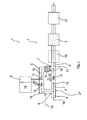
- FIG. 1 is shown schematically and merely by way of example a first embodiment of a regeneration device 1 according to the invention for a arranged in the exhaust line 2 of an internal combustion engine, not shown here particulate filter 3.
- the exhaust line 2 here has a raw gas line 21 with a first line section 4, from the upstream of the particulate filter 3 a feed line 5 branches off at a branch point 6, this supply line 5 also turn upstream of the particulate filter 3 at an outlet point 7 with the downstream of the branch point 6 continued line section 4 'is merged to form the power section 4 ".
- an HC oxidation catalyst 8 is arranged in the supply line 5.
- the regeneration device 1 comprises a metering device 9 for fuel, which, as is shown very schematically, is coupled to a control and / or regulating device 10.
- the metering device 9 has a running in the manner of a bypass line, projecting into the feed line 5 injection nozzle 11 through which the fuel 12 controlled or regulated with the control and / or regulating device 10 at predetermined times in predetermined amounts in the supply line 5 upstream of the HC oxidation catalyst 8 is injected.
- a throttle valve 13 is further arranged, which is preferably also coupled to the control and / or regulating device 10. Further, in the line section 4 'in the region between the branch point 6 and the point of discharge 7, a throttle valve 14 is likewise arranged, which is preferably also coupled to the control and / or regulating device 10.
- the raw gas flow 15 coming from the internal combustion engine 15 can be controlled or regulated in a controlled manner into the supply line 5 and mass of an exhaust gas flow 16 to be heated.
- the arrows 22 represent here schematically the variable adjustment of the throttle valve 13, 14 represents.
- the exhaust gas stream 16 to be heated takes along its flow path upstream of the HC oxidation catalyst 8 the injected fuel or the injected hydrocarbons and flows through fuel enriched the HC oxidation catalyst 8, in which then an exothermic reaction or oxidation takes place, due to the exhaust gas stream 16 a predetermined temperature is heated.
- This heated exhaust gas stream 16 ' is then fed back downstream of the HC oxidation catalyst 8 at the discharge point 7 to the raw gas stream 15' flowing via the line section 4, where the two exhaust gas streams 15 ', 16' mix, so that subsequently, after mixing two exhaust gas streams 15 ', 16', a hot Rohabgasstrom 17 flows to the particle filter 3, where the carbonaceous particles stored in the particulate filter 3 are converted to CO, CO 2 , N 2 and NO, whereby the particulate filter 3 is regenerated.
- the throttle valve 13 is controlled so that it substantially completely closes the supply line 5, so that no or virtually no exhaust gas flow reaches the particle filter 3 via the feed line 5. In this case, then the throttle valve 14 is fully open.
- the throttle valve 13 is opened so far that a predetermined amount of exhaust gas is diverted from the raw exhaust stream 15 and in the manner already described above, a hot Rohabgasstrom 17 is generated, which is then fed to the particulate filter 3 to its regeneration.
- the throttle valve 14 may be more or less closed and the Throttle valve 13 are opened, whereby the Rohabgasstrom 15 'is strongly throttled by the line section 4', so that a larger amount of exhaust gas 16 and thus a larger amount of oxygen via the supply line 5 and thus via the HC oxidation catalyst 8 to the particle filter 3 flows.
- a charge air side fresh air flow are mixed into the heated exhaust gas stream 16 to the heating power at predetermined times or when reaching predetermined exhaust gas flow temperatures and / or falls below a predetermined lambda value or oxygen value Raise the available amount of oxygen further increase.
- the particulate filter 3 is also followed by a NO x reduction catalyst 23, for example an SCR catalytic converter.
- a NO x reduction catalyst 23 for example an SCR catalytic converter.
- a further HC oxidation catalyst 18 may be provided by means of the high hydrocarbon concentrations downstream of the particulate filter 3 can be reliably avoided.
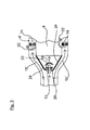
- Fig. 2 is shown schematically and by way of example a second embodiment of a regeneration device 1 according to the invention, in which arranged for a particularly compact and thus space-saving construction of the HC oxidation catalyst 8 within a HC-oxidation catalyst 8 annular Umhabgastechnischs Kunststoffes and recorded.
- the raw exhaust gas stream 15 flowing through a first line section 4 of the raw exhaust gas line 21 in the direction of the HC oxidation catalyst is here through one or more flow guide elements 24 into a first exhaust gas flow 15 'flowing through only the line section 4' of the raw exhaust gas line 21 and into one Oxidation catalyst 8 by flowing, to be heated second exhaust gas stream 16 divided.
- the raw exhaust gas stream 15 flowing through a first line section 4 of the raw exhaust gas line 21 in the direction of the HC oxidation catalyst is here through one or more flow guide elements 24 into a first exhaust gas flow 15 'flowing through only the line section 4' of the raw exhaust gas line 21 and into one Oxidation catalyst 8 by flowing, to be heated second exhaust
- the mass of the second exhaust gas flow 16 flowing through the HC oxidation catalytic converter 8 is thus predetermined by the geometry of the flow guide elements 24 and / or by the position of the throttle valve 13 mounted thereon, for example.
- the control of the throttle valve 13 is again via the electronic control and / or regulating device 10, in dependence on predetermined regeneration or operating parameters, analogous to previously in connection with the embodiments of Fig. 1 described control of the throttle valve 13th
- an injection nozzle 11 of a metering device 9 can be injected by the fuel 12 into the second exhaust gas stream 14, so that takes place in the HC oxidation catalyst 8, an exothermic reaction and the HC oxidation catalyst leaving hot exhaust gas stream 16 'is mixed together with the raw exhaust gas stream 15' to a hot exhaust gas stream 17.
- This hot exhaust gas stream 17 then flows through the particulate filter 3 and then through a NO x reduction catalyst 23, as previously described in connection with the Fig. 1 has been described.
- the flow regions formed by the flow guide elements 24 then form analogously to the embodiments according to FIGS FIGS. 1 and 2 in turn, a branched off from the line section 4 line section 4 'and a "supply line” 5, which are then brought together in the region downstream of the HC oxidation catalyst 8 again to a common line section 4 ".
- throttle valve (s) 14 may be provided by means of which the annulus geometry is more or less closable.
- the selected representation of two throttle valves 14 does not take into account this annular space geometry and serves only for the schematic representation.
Landscapes
- Engineering & Computer Science (AREA)
- Chemical & Material Sciences (AREA)
- Combustion & Propulsion (AREA)
- Mechanical Engineering (AREA)
- General Engineering & Computer Science (AREA)
- Chemical Kinetics & Catalysis (AREA)
- Health & Medical Sciences (AREA)
- Toxicology (AREA)
- Exhaust Gas After Treatment (AREA)
- Processes For Solid Components From Exhaust (AREA)
Priority Applications (1)
| Application Number | Priority Date | Filing Date | Title |
|---|---|---|---|
| EP09012063.5A EP2305978B1 (fr) | 2009-09-23 | 2009-09-23 | Procédé et dispositif de régénération d'un filtre à particules agencé dans le système d'échappement d'un moteur à combustion interne |
Applications Claiming Priority (1)
| Application Number | Priority Date | Filing Date | Title |
|---|---|---|---|
| EP09012063.5A EP2305978B1 (fr) | 2009-09-23 | 2009-09-23 | Procédé et dispositif de régénération d'un filtre à particules agencé dans le système d'échappement d'un moteur à combustion interne |
Publications (2)
| Publication Number | Publication Date |
|---|---|
| EP2305978A1 true EP2305978A1 (fr) | 2011-04-06 |
| EP2305978B1 EP2305978B1 (fr) | 2016-11-16 |
Family
ID=41668210
Family Applications (1)
| Application Number | Title | Priority Date | Filing Date |
|---|---|---|---|
| EP09012063.5A Active EP2305978B1 (fr) | 2009-09-23 | 2009-09-23 | Procédé et dispositif de régénération d'un filtre à particules agencé dans le système d'échappement d'un moteur à combustion interne |
Country Status (1)
| Country | Link |
|---|---|
| EP (1) | EP2305978B1 (fr) |
Cited By (5)
| Publication number | Priority date | Publication date | Assignee | Title |
|---|---|---|---|---|
| WO2012130789A1 (fr) * | 2011-03-28 | 2012-10-04 | Hjs Emission Technology Gmbh & Co. Kg | Procédé pour alimenter en énergie thermique une unité d'épuration de gaz d'échappement montée dans le système d'échappement d'un moteur à combustion interne |
| WO2013104633A1 (fr) * | 2012-01-09 | 2013-07-18 | Eminox Limited | Système d'échappement et procédé pour réduire les particules et les émissions de no2 |
| EP2693011A1 (fr) * | 2012-07-30 | 2014-02-05 | Benteler Automobiltechnik GmbH | Agencement de clapet de gaz d'échappement avec dérivation intégrée |
| CN105003326A (zh) * | 2015-07-28 | 2015-10-28 | 青岛双瑞海洋环境工程股份有限公司 | 船舶废气脱硝系统 |
| CN106677861A (zh) * | 2015-07-08 | 2017-05-17 | 保时捷股份公司 | 用于机动车辆的颗粒过滤器 |
Citations (8)
| Publication number | Priority date | Publication date | Assignee | Title |
|---|---|---|---|---|
| EP0341832A2 (fr) | 1988-05-13 | 1989-11-15 | Johnson Matthey Inc. | Traitement de gaz d'échappement de moteur diesel |
| EP1072765A2 (fr) | 1999-07-26 | 2001-01-31 | Man Nutzfahrzeuge Ag | Procédé et dispositif pour la séparation de particules fines des gaz d'échappement d'un moteur à combustion interne |
| DE10043613A1 (de) * | 2000-08-02 | 2002-02-14 | Fev Motorentech Gmbh | Regenerierbare Filteranordnung zur Reinigung von Abgasen einer Kolbenbrennkraftmaschine |
| WO2006104240A1 (fr) * | 2005-03-28 | 2006-10-05 | Toyota Jidosha Kabushiki Kaisha | Systeme de purification de gaz d'echappement de moteur a combustion interne |
| DE102005055240A1 (de) | 2005-11-19 | 2007-05-31 | Daimlerchrysler Ag | Abgasnachbehandlungsvorrichtung für eine Brennkraftmaschine |
| DE102007033424A1 (de) * | 2007-07-18 | 2009-01-22 | Man Nutzfahrzeuge Ag | Selbstreinigendes Abgasnachbehandlungssystem |
| FR2924749A1 (fr) * | 2007-12-10 | 2009-06-12 | Peugeot Citroen Automobiles Sa | Ligne d'echappement de gaz pour moteur de vehicule automobile equipee d'un catalyseur de reduction selective des oxydes d'azote |
| EP2154344A2 (fr) * | 2008-08-12 | 2010-02-17 | MAN Nutzfahrzeuge AG | Procédé et dispositif de régénération d'un filtre à particules agencé dans une ligne d'échappement d'un moteur à combustion interne |
-
2009
- 2009-09-23 EP EP09012063.5A patent/EP2305978B1/fr active Active
Patent Citations (8)
| Publication number | Priority date | Publication date | Assignee | Title |
|---|---|---|---|---|
| EP0341832A2 (fr) | 1988-05-13 | 1989-11-15 | Johnson Matthey Inc. | Traitement de gaz d'échappement de moteur diesel |
| EP1072765A2 (fr) | 1999-07-26 | 2001-01-31 | Man Nutzfahrzeuge Ag | Procédé et dispositif pour la séparation de particules fines des gaz d'échappement d'un moteur à combustion interne |
| DE10043613A1 (de) * | 2000-08-02 | 2002-02-14 | Fev Motorentech Gmbh | Regenerierbare Filteranordnung zur Reinigung von Abgasen einer Kolbenbrennkraftmaschine |
| WO2006104240A1 (fr) * | 2005-03-28 | 2006-10-05 | Toyota Jidosha Kabushiki Kaisha | Systeme de purification de gaz d'echappement de moteur a combustion interne |
| DE102005055240A1 (de) | 2005-11-19 | 2007-05-31 | Daimlerchrysler Ag | Abgasnachbehandlungsvorrichtung für eine Brennkraftmaschine |
| DE102007033424A1 (de) * | 2007-07-18 | 2009-01-22 | Man Nutzfahrzeuge Ag | Selbstreinigendes Abgasnachbehandlungssystem |
| FR2924749A1 (fr) * | 2007-12-10 | 2009-06-12 | Peugeot Citroen Automobiles Sa | Ligne d'echappement de gaz pour moteur de vehicule automobile equipee d'un catalyseur de reduction selective des oxydes d'azote |
| EP2154344A2 (fr) * | 2008-08-12 | 2010-02-17 | MAN Nutzfahrzeuge AG | Procédé et dispositif de régénération d'un filtre à particules agencé dans une ligne d'échappement d'un moteur à combustion interne |
Cited By (8)
| Publication number | Priority date | Publication date | Assignee | Title |
|---|---|---|---|---|
| WO2012130789A1 (fr) * | 2011-03-28 | 2012-10-04 | Hjs Emission Technology Gmbh & Co. Kg | Procédé pour alimenter en énergie thermique une unité d'épuration de gaz d'échappement montée dans le système d'échappement d'un moteur à combustion interne |
| US8904764B2 (en) | 2011-03-28 | 2014-12-09 | Hjs Emission Technology Gmbh & Co. Kg | Method for feeding thermal energy into an exhaust emission control unit connected in the exhaust gas system of an internal combustion engine |
| RU2592362C2 (ru) * | 2011-03-28 | 2016-07-20 | ХЙС ЭМИШН ТЕКНОЛОДЖИ ГМБХ унд КО. КГ | Способ подачи тепловой энергии в устройство для нейтрализации отработавших газов, размещенное в выпускном тракте двигателя внутреннего сгорания |
| WO2013104633A1 (fr) * | 2012-01-09 | 2013-07-18 | Eminox Limited | Système d'échappement et procédé pour réduire les particules et les émissions de no2 |
| EP2693011A1 (fr) * | 2012-07-30 | 2014-02-05 | Benteler Automobiltechnik GmbH | Agencement de clapet de gaz d'échappement avec dérivation intégrée |
| CN106677861A (zh) * | 2015-07-08 | 2017-05-17 | 保时捷股份公司 | 用于机动车辆的颗粒过滤器 |
| CN106677861B (zh) * | 2015-07-08 | 2020-03-10 | 保时捷股份公司 | 用于机动车辆的颗粒过滤器 |
| CN105003326A (zh) * | 2015-07-28 | 2015-10-28 | 青岛双瑞海洋环境工程股份有限公司 | 船舶废气脱硝系统 |
Also Published As
| Publication number | Publication date |
|---|---|
| EP2305978B1 (fr) | 2016-11-16 |
Similar Documents
| Publication | Publication Date | Title |
|---|---|---|
| EP2154345B1 (fr) | Procédé et dispositif de régénération d'un filtre à particules agencé dans le système d'échappement d'un moteur à combustion interne | |
| DE102008038719A1 (de) | Verfahren und Vorrichtung zur Regeneration eines im Abgasstrang einer Brennkraftmaschine angeordneten Partikelfilters | |
| EP2154344B1 (fr) | Procédé et dispositif de régénération d'un filtre à particules agencé dans une ligne d'échappement d'un moteur à combustion interne | |
| EP2379851B1 (fr) | Dispositif et procédé de régénération d'un filtre à particules disposé dans la conduite de gaz d'échappement d'un moteur à combustion interne | |
| EP2075050B1 (fr) | Procédé et dispositif d'amélioration de l'hydrolyse d'un moyen de réduction dans un système de retraitement des gaz d'échappement | |
| EP1892395B1 (fr) | Système de traitement de gaz d'échappement | |
| EP1771644B1 (fr) | Systeme d'echappement, notamment pour un moteur a combustion interne d'un vehicule a moteur | |
| EP1892394B1 (fr) | Système de traitement postérieur de gaz d'échappement | |
| EP1900916B1 (fr) | Système de traitement postérieur de gaz d'échappement | |
| EP2452055B1 (fr) | Procede et dispositif pour la regeneration d'un filtre a particule dans une ligne d'echappement d'un moteur a combustion | |
| EP2198134B1 (fr) | Procédé pour réduire les émissions de dioxyde d'azote sur un véhicule automobile doté d'un moteur à combustion interne fonctionnant avec un mélange pauvre | |
| EP2743470B1 (fr) | Procédé et dispositif d'élévation de la température des gaz de combustion dans la ligne d'échappement d'un moteur à combustion interne turbochargé | |
| EP2376749B1 (fr) | Procédé de conrôle de composants pour le post-traitement de gaz d'échappement et dispositif de post-traitement de gaz d'échappement | |
| EP2305978B1 (fr) | Procédé et dispositif de régénération d'un filtre à particules agencé dans le système d'échappement d'un moteur à combustion interne | |
| DE19955324A1 (de) | Vorrichtung und Verfahren zum Reduzieren von schädlichen Bestandteilen im Abgas einer Brennkraftmaschine, insbesondere einer Diesel-Brennkraftmaschine | |
| WO2009065555A1 (fr) | Dispositif de post-traitement des gaz d'échappement pour un moteur à combustion interne, et procédé de post-traitement des gaz d'échappement d'un moteur à combustion interne | |
| DE102009004416A1 (de) | Verfahren zum Betrieb von Komponenten der Abgasnachbehandlung sowie Abgasnachbehandlungsvorrichung | |
| WO2010070100A1 (fr) | Ensemble d'épuration de gaz d'échappement, et procédé permettant de faire fonctionner un ensemble d'épuration de gaz d'échappement | |
| DE102009003738A1 (de) | Abgasreinigungsanlage sowie Verfahren zum Zuführen von thermischer Energie zum Auslösen und/oder Unterstützen eines in einer Abgasreinigungsanlage ablaufenden Prozesses | |
| EP2169192B1 (fr) | Dispositif et procédé d'injection de carburant dans le flux de gaz d'échappement d'un moteur à combustion interne, notamment pour la régénération d'un filtre à particules | |
| DE102005038187A1 (de) | Abgasreinigungsvorrichtung und Verfahren zum Betreiben derselben | |
| DE102009005733A1 (de) | Vorrichtung und Verfahren zur Regeneration eines im Abgastrakt einer Brennkraftmaschine angeordneten Partikelfilters | |
| DE102014008056B4 (de) | Verfahren zum Betreiben einer Abgasanlage einer Verbrennungskraftmaschine, insbesondere für einen Kraftwagen | |
| DE102006043151A1 (de) | Verfahren und Vorrichtung zur Regeneration eines Partikelfilters | |
| DE102004062897A1 (de) | System und Verfahren für die Nachbehandlung von Abgasen aus Verbrennungskraftmaschinen |
Legal Events
| Date | Code | Title | Description |
|---|---|---|---|
| PUAI | Public reference made under article 153(3) epc to a published international application that has entered the european phase |
Free format text: ORIGINAL CODE: 0009012 |
|
| 17P | Request for examination filed |
Effective date: 20100317 |
|
| AK | Designated contracting states |
Kind code of ref document: A1 Designated state(s): AT BE BG CH CY CZ DE DK EE ES FI FR GB GR HR HU IE IS IT LI LT LU LV MC MK MT NL NO PL PT RO SE SI SK SM TR |
|
| AX | Request for extension of the european patent |
Extension state: AL BA RS |
|
| RIN1 | Information on inventor provided before grant (corrected) |
Inventor name: DOERING, ANDREAS |
|
| RIC1 | Information provided on ipc code assigned before grant |
Ipc: F01N 9/00 20060101ALI20160531BHEP Ipc: F01N 3/023 20060101ALI20160531BHEP Ipc: F01N 13/00 20100101ALI20160531BHEP Ipc: F01N 3/035 20060101ALI20160531BHEP Ipc: F01N 3/20 20060101ALI20160531BHEP Ipc: F01N 3/025 20060101AFI20160531BHEP |
|
| GRAP | Despatch of communication of intention to grant a patent |
Free format text: ORIGINAL CODE: EPIDOSNIGR1 |
|
| INTG | Intention to grant announced |
Effective date: 20160714 |
|
| GRAS | Grant fee paid |
Free format text: ORIGINAL CODE: EPIDOSNIGR3 |
|
| GRAA | (expected) grant |
Free format text: ORIGINAL CODE: 0009210 |
|
| RBV | Designated contracting states (corrected) |
Designated state(s): AT BE BG CH CY CZ DK EE ES FI FR GB GR HR HU IE IS IT LI LT LU LV MC MK MT NL NO PL PT RO SE SI SK SM TR |
|
| REG | Reference to a national code |
Ref country code: DE Ref legal event code: R108 |
|
| AK | Designated contracting states |
Kind code of ref document: B1 Designated state(s): AT BE BG CH CY CZ DK EE ES FI FR GB GR HR HU IE IS IT LI LT LU LV MC MK MT NL NO PL PT RO SE SI SK SM TR |
|
| REG | Reference to a national code |
Ref country code: GB Ref legal event code: FG4D Free format text: NOT ENGLISH |
|
| REG | Reference to a national code |
Ref country code: CH Ref legal event code: EP |
|
| REG | Reference to a national code |
Ref country code: IE Ref legal event code: FG4D Free format text: LANGUAGE OF EP DOCUMENT: GERMAN |
|
| REG | Reference to a national code |
Ref country code: AT Ref legal event code: REF Ref document number: 846167 Country of ref document: AT Kind code of ref document: T Effective date: 20161215 |
|
| REG | Reference to a national code |
Ref country code: SE Ref legal event code: TRGR |
|
| REG | Reference to a national code |
Ref country code: NL Ref legal event code: FP |
|
| PG25 | Lapsed in a contracting state [announced via postgrant information from national office to epo] |
Ref country code: LV Free format text: LAPSE BECAUSE OF FAILURE TO SUBMIT A TRANSLATION OF THE DESCRIPTION OR TO PAY THE FEE WITHIN THE PRESCRIBED TIME-LIMIT Effective date: 20161116 |
|
| REG | Reference to a national code |
Ref country code: LT Ref legal event code: MG4D |
|
| PG25 | Lapsed in a contracting state [announced via postgrant information from national office to epo] |
Ref country code: NO Free format text: LAPSE BECAUSE OF FAILURE TO SUBMIT A TRANSLATION OF THE DESCRIPTION OR TO PAY THE FEE WITHIN THE PRESCRIBED TIME-LIMIT Effective date: 20170216 Ref country code: LT Free format text: LAPSE BECAUSE OF FAILURE TO SUBMIT A TRANSLATION OF THE DESCRIPTION OR TO PAY THE FEE WITHIN THE PRESCRIBED TIME-LIMIT Effective date: 20161116 Ref country code: GR Free format text: LAPSE BECAUSE OF FAILURE TO SUBMIT A TRANSLATION OF THE DESCRIPTION OR TO PAY THE FEE WITHIN THE PRESCRIBED TIME-LIMIT Effective date: 20170217 |
|
| PG25 | Lapsed in a contracting state [announced via postgrant information from national office to epo] |
Ref country code: FI Free format text: LAPSE BECAUSE OF FAILURE TO SUBMIT A TRANSLATION OF THE DESCRIPTION OR TO PAY THE FEE WITHIN THE PRESCRIBED TIME-LIMIT Effective date: 20161116 Ref country code: PL Free format text: LAPSE BECAUSE OF FAILURE TO SUBMIT A TRANSLATION OF THE DESCRIPTION OR TO PAY THE FEE WITHIN THE PRESCRIBED TIME-LIMIT Effective date: 20161116 Ref country code: ES Free format text: LAPSE BECAUSE OF FAILURE TO SUBMIT A TRANSLATION OF THE DESCRIPTION OR TO PAY THE FEE WITHIN THE PRESCRIBED TIME-LIMIT Effective date: 20161116 Ref country code: PT Free format text: LAPSE BECAUSE OF FAILURE TO SUBMIT A TRANSLATION OF THE DESCRIPTION OR TO PAY THE FEE WITHIN THE PRESCRIBED TIME-LIMIT Effective date: 20170316 Ref country code: HR Free format text: LAPSE BECAUSE OF FAILURE TO SUBMIT A TRANSLATION OF THE DESCRIPTION OR TO PAY THE FEE WITHIN THE PRESCRIBED TIME-LIMIT Effective date: 20161116 |
|
| PG25 | Lapsed in a contracting state [announced via postgrant information from national office to epo] |
Ref country code: DK Free format text: LAPSE BECAUSE OF FAILURE TO SUBMIT A TRANSLATION OF THE DESCRIPTION OR TO PAY THE FEE WITHIN THE PRESCRIBED TIME-LIMIT Effective date: 20161116 Ref country code: EE Free format text: LAPSE BECAUSE OF FAILURE TO SUBMIT A TRANSLATION OF THE DESCRIPTION OR TO PAY THE FEE WITHIN THE PRESCRIBED TIME-LIMIT Effective date: 20161116 Ref country code: SK Free format text: LAPSE BECAUSE OF FAILURE TO SUBMIT A TRANSLATION OF THE DESCRIPTION OR TO PAY THE FEE WITHIN THE PRESCRIBED TIME-LIMIT Effective date: 20161116 Ref country code: RO Free format text: LAPSE BECAUSE OF FAILURE TO SUBMIT A TRANSLATION OF THE DESCRIPTION OR TO PAY THE FEE WITHIN THE PRESCRIBED TIME-LIMIT Effective date: 20161116 Ref country code: CZ Free format text: LAPSE BECAUSE OF FAILURE TO SUBMIT A TRANSLATION OF THE DESCRIPTION OR TO PAY THE FEE WITHIN THE PRESCRIBED TIME-LIMIT Effective date: 20161116 |
|
| PG25 | Lapsed in a contracting state [announced via postgrant information from national office to epo] |
Ref country code: SM Free format text: LAPSE BECAUSE OF FAILURE TO SUBMIT A TRANSLATION OF THE DESCRIPTION OR TO PAY THE FEE WITHIN THE PRESCRIBED TIME-LIMIT Effective date: 20161116 Ref country code: BG Free format text: LAPSE BECAUSE OF FAILURE TO SUBMIT A TRANSLATION OF THE DESCRIPTION OR TO PAY THE FEE WITHIN THE PRESCRIBED TIME-LIMIT Effective date: 20170216 |
|
| PLBE | No opposition filed within time limit |
Free format text: ORIGINAL CODE: 0009261 |
|
| STAA | Information on the status of an ep patent application or granted ep patent |
Free format text: STATUS: NO OPPOSITION FILED WITHIN TIME LIMIT |
|
| REG | Reference to a national code |
Ref country code: FR Ref legal event code: PLFP Year of fee payment: 9 |
|
| 26N | No opposition filed |
Effective date: 20170817 |
|
| PG25 | Lapsed in a contracting state [announced via postgrant information from national office to epo] |
Ref country code: SI Free format text: LAPSE BECAUSE OF FAILURE TO SUBMIT A TRANSLATION OF THE DESCRIPTION OR TO PAY THE FEE WITHIN THE PRESCRIBED TIME-LIMIT Effective date: 20161116 |
|
| REG | Reference to a national code |
Ref country code: CH Ref legal event code: PL |
|
| GBPC | Gb: european patent ceased through non-payment of renewal fee |
Effective date: 20170923 |
|
| PG25 | Lapsed in a contracting state [announced via postgrant information from national office to epo] |
Ref country code: MC Free format text: LAPSE BECAUSE OF FAILURE TO SUBMIT A TRANSLATION OF THE DESCRIPTION OR TO PAY THE FEE WITHIN THE PRESCRIBED TIME-LIMIT Effective date: 20161116 |
|
| REG | Reference to a national code |
Ref country code: IE Ref legal event code: MM4A |
|
| REG | Reference to a national code |
Ref country code: BE Ref legal event code: MM Effective date: 20170930 |
|
| PG25 | Lapsed in a contracting state [announced via postgrant information from national office to epo] |
Ref country code: LU Free format text: LAPSE BECAUSE OF NON-PAYMENT OF DUE FEES Effective date: 20170923 |
|
| PG25 | Lapsed in a contracting state [announced via postgrant information from national office to epo] |
Ref country code: GB Free format text: LAPSE BECAUSE OF NON-PAYMENT OF DUE FEES Effective date: 20170923 Ref country code: CH Free format text: LAPSE BECAUSE OF NON-PAYMENT OF DUE FEES Effective date: 20170930 Ref country code: LI Free format text: LAPSE BECAUSE OF NON-PAYMENT OF DUE FEES Effective date: 20170930 Ref country code: IE Free format text: LAPSE BECAUSE OF NON-PAYMENT OF DUE FEES Effective date: 20170923 |
|
| PG25 | Lapsed in a contracting state [announced via postgrant information from national office to epo] |
Ref country code: BE Free format text: LAPSE BECAUSE OF NON-PAYMENT OF DUE FEES Effective date: 20170930 |
|
| PG25 | Lapsed in a contracting state [announced via postgrant information from national office to epo] |
Ref country code: MT Free format text: LAPSE BECAUSE OF FAILURE TO SUBMIT A TRANSLATION OF THE DESCRIPTION OR TO PAY THE FEE WITHIN THE PRESCRIBED TIME-LIMIT Effective date: 20161116 |
|
| REG | Reference to a national code |
Ref country code: FR Ref legal event code: PLFP Year of fee payment: 10 |
|
| REG | Reference to a national code |
Ref country code: AT Ref legal event code: MM01 Ref document number: 846167 Country of ref document: AT Kind code of ref document: T Effective date: 20170923 |
|
| PG25 | Lapsed in a contracting state [announced via postgrant information from national office to epo] |
Ref country code: AT Free format text: LAPSE BECAUSE OF NON-PAYMENT OF DUE FEES Effective date: 20170923 |
|
| PG25 | Lapsed in a contracting state [announced via postgrant information from national office to epo] |
Ref country code: HU Free format text: LAPSE BECAUSE OF FAILURE TO SUBMIT A TRANSLATION OF THE DESCRIPTION OR TO PAY THE FEE WITHIN THE PRESCRIBED TIME-LIMIT; INVALID AB INITIO Effective date: 20090923 |
|
| PG25 | Lapsed in a contracting state [announced via postgrant information from national office to epo] |
Ref country code: CY Free format text: LAPSE BECAUSE OF NON-PAYMENT OF DUE FEES Effective date: 20161116 |
|
| PG25 | Lapsed in a contracting state [announced via postgrant information from national office to epo] |
Ref country code: MK Free format text: LAPSE BECAUSE OF FAILURE TO SUBMIT A TRANSLATION OF THE DESCRIPTION OR TO PAY THE FEE WITHIN THE PRESCRIBED TIME-LIMIT Effective date: 20161116 |
|
| PG25 | Lapsed in a contracting state [announced via postgrant information from national office to epo] |
Ref country code: TR Free format text: LAPSE BECAUSE OF FAILURE TO SUBMIT A TRANSLATION OF THE DESCRIPTION OR TO PAY THE FEE WITHIN THE PRESCRIBED TIME-LIMIT Effective date: 20161116 |
|
| PG25 | Lapsed in a contracting state [announced via postgrant information from national office to epo] |
Ref country code: IS Free format text: LAPSE BECAUSE OF FAILURE TO SUBMIT A TRANSLATION OF THE DESCRIPTION OR TO PAY THE FEE WITHIN THE PRESCRIBED TIME-LIMIT Effective date: 20170316 |
|
| PGFP | Annual fee paid to national office [announced via postgrant information from national office to epo] |
Ref country code: NL Payment date: 20230926 Year of fee payment: 15 Ref country code: IT Payment date: 20230920 Year of fee payment: 15 |
|
| PGFP | Annual fee paid to national office [announced via postgrant information from national office to epo] |
Ref country code: SE Payment date: 20230926 Year of fee payment: 15 Ref country code: FR Payment date: 20230926 Year of fee payment: 15 |