EP2305978A1 - Method and device for regenerating a particulate filter built into the exhaust gas flow of a combustion engine - Google Patents
Method and device for regenerating a particulate filter built into the exhaust gas flow of a combustion engine Download PDFInfo
- Publication number
- EP2305978A1 EP2305978A1 EP09012063A EP09012063A EP2305978A1 EP 2305978 A1 EP2305978 A1 EP 2305978A1 EP 09012063 A EP09012063 A EP 09012063A EP 09012063 A EP09012063 A EP 09012063A EP 2305978 A1 EP2305978 A1 EP 2305978A1
- Authority
- EP
- European Patent Office
- Prior art keywords
- exhaust gas
- particulate filter
- gas flow
- heated
- line
- Prior art date
- Legal status (The legal status is an assumption and is not a legal conclusion. Google has not performed a legal analysis and makes no representation as to the accuracy of the status listed.)
- Granted
Links
- 238000000034 method Methods 0.000 title claims abstract description 18
- 238000002485 combustion reaction Methods 0.000 title claims abstract description 15
- 230000001172 regenerating effect Effects 0.000 title abstract description 4
- 238000007254 oxidation reaction Methods 0.000 claims abstract description 63
- 230000003647 oxidation Effects 0.000 claims abstract description 60
- 238000011144 upstream manufacturing Methods 0.000 claims abstract description 38
- 238000010438 heat treatment Methods 0.000 claims abstract description 31
- 239000007789 gas Substances 0.000 claims description 112
- 239000003054 catalyst Substances 0.000 claims description 83
- 150000002430 hydrocarbons Chemical class 0.000 claims description 56
- 229930195733 hydrocarbon Natural products 0.000 claims description 53
- 230000008929 regeneration Effects 0.000 claims description 42
- 238000011069 regeneration method Methods 0.000 claims description 42
- 239000002245 particle Substances 0.000 claims description 25
- QVGXLLKOCUKJST-UHFFFAOYSA-N atomic oxygen Chemical compound [O] QVGXLLKOCUKJST-UHFFFAOYSA-N 0.000 claims description 16
- 229910052760 oxygen Inorganic materials 0.000 claims description 16
- 239000001301 oxygen Substances 0.000 claims description 16
- 230000001105 regulatory effect Effects 0.000 claims description 15
- 230000003197 catalytic effect Effects 0.000 claims description 9
- 238000006243 chemical reaction Methods 0.000 claims description 7
- 239000004215 Carbon black (E152) Substances 0.000 claims description 6
- 230000010718 Oxidation Activity Effects 0.000 claims description 5
- 230000001276 controlling effect Effects 0.000 claims description 2
- 230000001747 exhibiting effect Effects 0.000 claims 1
- 230000001590 oxidative effect Effects 0.000 claims 1
- MWUXSHHQAYIFBG-UHFFFAOYSA-N Nitric oxide Chemical compound O=[N] MWUXSHHQAYIFBG-UHFFFAOYSA-N 0.000 description 49
- 239000000446 fuel Substances 0.000 description 9
- 230000015572 biosynthetic process Effects 0.000 description 5
- BASFCYQUMIYNBI-UHFFFAOYSA-N platinum Chemical compound [Pt] BASFCYQUMIYNBI-UHFFFAOYSA-N 0.000 description 5
- 229910002091 carbon monoxide Inorganic materials 0.000 description 4
- 238000002347 injection Methods 0.000 description 4
- 239000007924 injection Substances 0.000 description 4
- 238000002156 mixing Methods 0.000 description 4
- 239000010457 zeolite Substances 0.000 description 4
- 238000010276 construction Methods 0.000 description 3
- 239000004071 soot Substances 0.000 description 3
- XEEYBQQBJWHFJM-UHFFFAOYSA-N Iron Chemical compound [Fe] XEEYBQQBJWHFJM-UHFFFAOYSA-N 0.000 description 2
- GWEVSGVZZGPLCZ-UHFFFAOYSA-N Titan oxide Chemical compound O=[Ti]=O GWEVSGVZZGPLCZ-UHFFFAOYSA-N 0.000 description 2
- GNTDGMZSJNCJKK-UHFFFAOYSA-N divanadium pentaoxide Chemical compound O=[V](=O)O[V](=O)=O GNTDGMZSJNCJKK-UHFFFAOYSA-N 0.000 description 2
- 239000007800 oxidant agent Substances 0.000 description 2
- 229910052697 platinum Inorganic materials 0.000 description 2
- 238000000926 separation method Methods 0.000 description 2
- WFKWXMTUELFFGS-UHFFFAOYSA-N tungsten Chemical compound [W] WFKWXMTUELFFGS-UHFFFAOYSA-N 0.000 description 2
- 229910052721 tungsten Inorganic materials 0.000 description 2
- 239000010937 tungsten Substances 0.000 description 2
- MGWGWNFMUOTEHG-UHFFFAOYSA-N 4-(3,5-dimethylphenyl)-1,3-thiazol-2-amine Chemical compound CC1=CC(C)=CC(C=2N=C(N)SC=2)=C1 MGWGWNFMUOTEHG-UHFFFAOYSA-N 0.000 description 1
- OYPRJOBELJOOCE-UHFFFAOYSA-N Calcium Chemical compound [Ca] OYPRJOBELJOOCE-UHFFFAOYSA-N 0.000 description 1
- OKTJSMMVPCPJKN-UHFFFAOYSA-N Carbon Chemical compound [C] OKTJSMMVPCPJKN-UHFFFAOYSA-N 0.000 description 1
- 229910052684 Cerium Inorganic materials 0.000 description 1
- RYGMFSIKBFXOCR-UHFFFAOYSA-N Copper Chemical compound [Cu] RYGMFSIKBFXOCR-UHFFFAOYSA-N 0.000 description 1
- GRYLNZFGIOXLOG-UHFFFAOYSA-N Nitric acid Chemical compound O[N+]([O-])=O GRYLNZFGIOXLOG-UHFFFAOYSA-N 0.000 description 1
- NINIDFKCEFEMDL-UHFFFAOYSA-N Sulfur Chemical compound [S] NINIDFKCEFEMDL-UHFFFAOYSA-N 0.000 description 1
- QAOWNCQODCNURD-UHFFFAOYSA-N Sulfuric acid Chemical compound OS(O)(=O)=O QAOWNCQODCNURD-UHFFFAOYSA-N 0.000 description 1
- 229910052788 barium Inorganic materials 0.000 description 1
- DSAJWYNOEDNPEQ-UHFFFAOYSA-N barium atom Chemical compound [Ba] DSAJWYNOEDNPEQ-UHFFFAOYSA-N 0.000 description 1
- 229910052791 calcium Inorganic materials 0.000 description 1
- 239000011575 calcium Substances 0.000 description 1
- 229910052799 carbon Inorganic materials 0.000 description 1
- GWXLDORMOJMVQZ-UHFFFAOYSA-N cerium Chemical compound [Ce] GWXLDORMOJMVQZ-UHFFFAOYSA-N 0.000 description 1
- 229910017052 cobalt Inorganic materials 0.000 description 1
- 239000010941 cobalt Substances 0.000 description 1
- GUTLYIVDDKVIGB-UHFFFAOYSA-N cobalt atom Chemical compound [Co] GUTLYIVDDKVIGB-UHFFFAOYSA-N 0.000 description 1
- 239000000470 constituent Substances 0.000 description 1
- 238000001816 cooling Methods 0.000 description 1
- 229910052802 copper Inorganic materials 0.000 description 1
- 239000010949 copper Substances 0.000 description 1
- 230000007797 corrosion Effects 0.000 description 1
- 238000005260 corrosion Methods 0.000 description 1
- 230000001419 dependent effect Effects 0.000 description 1
- 230000000694 effects Effects 0.000 description 1
- 239000010419 fine particle Substances 0.000 description 1
- 239000000295 fuel oil Substances 0.000 description 1
- 229910052742 iron Inorganic materials 0.000 description 1
- 239000000203 mixture Substances 0.000 description 1
- 239000010705 motor oil Substances 0.000 description 1
- 229910017604 nitric acid Inorganic materials 0.000 description 1
- JCXJVPUVTGWSNB-UHFFFAOYSA-N nitrogen dioxide Inorganic materials O=[N]=O JCXJVPUVTGWSNB-UHFFFAOYSA-N 0.000 description 1
- 239000007787 solid Substances 0.000 description 1
- 239000000243 solution Substances 0.000 description 1
- 229910001220 stainless steel Inorganic materials 0.000 description 1
- 239000010935 stainless steel Substances 0.000 description 1
- 229910052717 sulfur Inorganic materials 0.000 description 1
- 239000011593 sulfur Substances 0.000 description 1
- 239000004408 titanium dioxide Substances 0.000 description 1
- 231100000331 toxic Toxicity 0.000 description 1
- 230000002588 toxic effect Effects 0.000 description 1
- 231100000419 toxicity Toxicity 0.000 description 1
- 230000001988 toxicity Effects 0.000 description 1
- 229910052720 vanadium Inorganic materials 0.000 description 1
- LEONUFNNVUYDNQ-UHFFFAOYSA-N vanadium atom Chemical compound [V] LEONUFNNVUYDNQ-UHFFFAOYSA-N 0.000 description 1
Images

Classifications
-
- F—MECHANICAL ENGINEERING; LIGHTING; HEATING; WEAPONS; BLASTING
- F01—MACHINES OR ENGINES IN GENERAL; ENGINE PLANTS IN GENERAL; STEAM ENGINES
- F01N—GAS-FLOW SILENCERS OR EXHAUST APPARATUS FOR MACHINES OR ENGINES IN GENERAL; GAS-FLOW SILENCERS OR EXHAUST APPARATUS FOR INTERNAL COMBUSTION ENGINES
- F01N3/00—Exhaust or silencing apparatus having means for purifying, rendering innocuous, or otherwise treating exhaust
- F01N3/02—Exhaust or silencing apparatus having means for purifying, rendering innocuous, or otherwise treating exhaust for cooling, or for removing solid constituents of, exhaust
- F01N3/021—Exhaust or silencing apparatus having means for purifying, rendering innocuous, or otherwise treating exhaust for cooling, or for removing solid constituents of, exhaust by means of filters
- F01N3/023—Exhaust or silencing apparatus having means for purifying, rendering innocuous, or otherwise treating exhaust for cooling, or for removing solid constituents of, exhaust by means of filters using means for regenerating the filters, e.g. by burning trapped particles
- F01N3/025—Exhaust or silencing apparatus having means for purifying, rendering innocuous, or otherwise treating exhaust for cooling, or for removing solid constituents of, exhaust by means of filters using means for regenerating the filters, e.g. by burning trapped particles using fuel burner or by adding fuel to exhaust
- F01N3/0253—Exhaust or silencing apparatus having means for purifying, rendering innocuous, or otherwise treating exhaust for cooling, or for removing solid constituents of, exhaust by means of filters using means for regenerating the filters, e.g. by burning trapped particles using fuel burner or by adding fuel to exhaust adding fuel to exhaust gases
-
- F—MECHANICAL ENGINEERING; LIGHTING; HEATING; WEAPONS; BLASTING
- F01—MACHINES OR ENGINES IN GENERAL; ENGINE PLANTS IN GENERAL; STEAM ENGINES
- F01N—GAS-FLOW SILENCERS OR EXHAUST APPARATUS FOR MACHINES OR ENGINES IN GENERAL; GAS-FLOW SILENCERS OR EXHAUST APPARATUS FOR INTERNAL COMBUSTION ENGINES
- F01N13/00—Exhaust or silencing apparatus characterised by constructional features ; Exhaust or silencing apparatus, or parts thereof, having pertinent characteristics not provided for in, or of interest apart from, groups F01N1/00 - F01N5/00, F01N9/00, F01N11/00
- F01N13/009—Exhaust or silencing apparatus characterised by constructional features ; Exhaust or silencing apparatus, or parts thereof, having pertinent characteristics not provided for in, or of interest apart from, groups F01N1/00 - F01N5/00, F01N9/00, F01N11/00 having two or more separate purifying devices arranged in series
-
- F—MECHANICAL ENGINEERING; LIGHTING; HEATING; WEAPONS; BLASTING
- F01—MACHINES OR ENGINES IN GENERAL; ENGINE PLANTS IN GENERAL; STEAM ENGINES
- F01N—GAS-FLOW SILENCERS OR EXHAUST APPARATUS FOR MACHINES OR ENGINES IN GENERAL; GAS-FLOW SILENCERS OR EXHAUST APPARATUS FOR INTERNAL COMBUSTION ENGINES
- F01N3/00—Exhaust or silencing apparatus having means for purifying, rendering innocuous, or otherwise treating exhaust
- F01N3/02—Exhaust or silencing apparatus having means for purifying, rendering innocuous, or otherwise treating exhaust for cooling, or for removing solid constituents of, exhaust
- F01N3/021—Exhaust or silencing apparatus having means for purifying, rendering innocuous, or otherwise treating exhaust for cooling, or for removing solid constituents of, exhaust by means of filters
- F01N3/023—Exhaust or silencing apparatus having means for purifying, rendering innocuous, or otherwise treating exhaust for cooling, or for removing solid constituents of, exhaust by means of filters using means for regenerating the filters, e.g. by burning trapped particles
- F01N3/0234—Exhaust or silencing apparatus having means for purifying, rendering innocuous, or otherwise treating exhaust for cooling, or for removing solid constituents of, exhaust by means of filters using means for regenerating the filters, e.g. by burning trapped particles using heat exchange means in the exhaust line
-
- F—MECHANICAL ENGINEERING; LIGHTING; HEATING; WEAPONS; BLASTING
- F01—MACHINES OR ENGINES IN GENERAL; ENGINE PLANTS IN GENERAL; STEAM ENGINES
- F01N—GAS-FLOW SILENCERS OR EXHAUST APPARATUS FOR MACHINES OR ENGINES IN GENERAL; GAS-FLOW SILENCERS OR EXHAUST APPARATUS FOR INTERNAL COMBUSTION ENGINES
- F01N3/00—Exhaust or silencing apparatus having means for purifying, rendering innocuous, or otherwise treating exhaust
- F01N3/02—Exhaust or silencing apparatus having means for purifying, rendering innocuous, or otherwise treating exhaust for cooling, or for removing solid constituents of, exhaust
- F01N3/021—Exhaust or silencing apparatus having means for purifying, rendering innocuous, or otherwise treating exhaust for cooling, or for removing solid constituents of, exhaust by means of filters
- F01N3/023—Exhaust or silencing apparatus having means for purifying, rendering innocuous, or otherwise treating exhaust for cooling, or for removing solid constituents of, exhaust by means of filters using means for regenerating the filters, e.g. by burning trapped particles
- F01N3/0235—Exhaust or silencing apparatus having means for purifying, rendering innocuous, or otherwise treating exhaust for cooling, or for removing solid constituents of, exhaust by means of filters using means for regenerating the filters, e.g. by burning trapped particles using exhaust gas throttling means
-
- F—MECHANICAL ENGINEERING; LIGHTING; HEATING; WEAPONS; BLASTING
- F01—MACHINES OR ENGINES IN GENERAL; ENGINE PLANTS IN GENERAL; STEAM ENGINES
- F01N—GAS-FLOW SILENCERS OR EXHAUST APPARATUS FOR MACHINES OR ENGINES IN GENERAL; GAS-FLOW SILENCERS OR EXHAUST APPARATUS FOR INTERNAL COMBUSTION ENGINES
- F01N3/00—Exhaust or silencing apparatus having means for purifying, rendering innocuous, or otherwise treating exhaust
- F01N3/02—Exhaust or silencing apparatus having means for purifying, rendering innocuous, or otherwise treating exhaust for cooling, or for removing solid constituents of, exhaust
- F01N3/021—Exhaust or silencing apparatus having means for purifying, rendering innocuous, or otherwise treating exhaust for cooling, or for removing solid constituents of, exhaust by means of filters
- F01N3/033—Exhaust or silencing apparatus having means for purifying, rendering innocuous, or otherwise treating exhaust for cooling, or for removing solid constituents of, exhaust by means of filters in combination with other devices
- F01N3/035—Exhaust or silencing apparatus having means for purifying, rendering innocuous, or otherwise treating exhaust for cooling, or for removing solid constituents of, exhaust by means of filters in combination with other devices with catalytic reactors, e.g. catalysed diesel particulate filters
-
- F—MECHANICAL ENGINEERING; LIGHTING; HEATING; WEAPONS; BLASTING
- F01—MACHINES OR ENGINES IN GENERAL; ENGINE PLANTS IN GENERAL; STEAM ENGINES
- F01N—GAS-FLOW SILENCERS OR EXHAUST APPARATUS FOR MACHINES OR ENGINES IN GENERAL; GAS-FLOW SILENCERS OR EXHAUST APPARATUS FOR INTERNAL COMBUSTION ENGINES
- F01N3/00—Exhaust or silencing apparatus having means for purifying, rendering innocuous, or otherwise treating exhaust
- F01N3/08—Exhaust or silencing apparatus having means for purifying, rendering innocuous, or otherwise treating exhaust for rendering innocuous
- F01N3/10—Exhaust or silencing apparatus having means for purifying, rendering innocuous, or otherwise treating exhaust for rendering innocuous by thermal or catalytic conversion of noxious components of exhaust
- F01N3/18—Exhaust or silencing apparatus having means for purifying, rendering innocuous, or otherwise treating exhaust for rendering innocuous by thermal or catalytic conversion of noxious components of exhaust characterised by methods of operation; Control
- F01N3/20—Exhaust or silencing apparatus having means for purifying, rendering innocuous, or otherwise treating exhaust for rendering innocuous by thermal or catalytic conversion of noxious components of exhaust characterised by methods of operation; Control specially adapted for catalytic conversion ; Methods of operation or control of catalytic converters
- F01N3/2053—By-passing catalytic reactors, e.g. to prevent overheating
-
- F—MECHANICAL ENGINEERING; LIGHTING; HEATING; WEAPONS; BLASTING
- F01—MACHINES OR ENGINES IN GENERAL; ENGINE PLANTS IN GENERAL; STEAM ENGINES
- F01N—GAS-FLOW SILENCERS OR EXHAUST APPARATUS FOR MACHINES OR ENGINES IN GENERAL; GAS-FLOW SILENCERS OR EXHAUST APPARATUS FOR INTERNAL COMBUSTION ENGINES
- F01N9/00—Electrical control of exhaust gas treating apparatus
- F01N9/002—Electrical control of exhaust gas treating apparatus of filter regeneration, e.g. detection of clogging
-
- F—MECHANICAL ENGINEERING; LIGHTING; HEATING; WEAPONS; BLASTING
- F01—MACHINES OR ENGINES IN GENERAL; ENGINE PLANTS IN GENERAL; STEAM ENGINES
- F01N—GAS-FLOW SILENCERS OR EXHAUST APPARATUS FOR MACHINES OR ENGINES IN GENERAL; GAS-FLOW SILENCERS OR EXHAUST APPARATUS FOR INTERNAL COMBUSTION ENGINES
- F01N2410/00—By-passing, at least partially, exhaust from inlet to outlet of apparatus, to atmosphere or to other device
- F01N2410/03—By-passing, at least partially, exhaust from inlet to outlet of apparatus, to atmosphere or to other device in case of low temperature
-
- F—MECHANICAL ENGINEERING; LIGHTING; HEATING; WEAPONS; BLASTING
- F01—MACHINES OR ENGINES IN GENERAL; ENGINE PLANTS IN GENERAL; STEAM ENGINES
- F01N—GAS-FLOW SILENCERS OR EXHAUST APPARATUS FOR MACHINES OR ENGINES IN GENERAL; GAS-FLOW SILENCERS OR EXHAUST APPARATUS FOR INTERNAL COMBUSTION ENGINES
- F01N2410/00—By-passing, at least partially, exhaust from inlet to outlet of apparatus, to atmosphere or to other device
- F01N2410/04—By-passing, at least partially, exhaust from inlet to outlet of apparatus, to atmosphere or to other device during regeneration period, e.g. of particle filter
-
- Y—GENERAL TAGGING OF NEW TECHNOLOGICAL DEVELOPMENTS; GENERAL TAGGING OF CROSS-SECTIONAL TECHNOLOGIES SPANNING OVER SEVERAL SECTIONS OF THE IPC; TECHNICAL SUBJECTS COVERED BY FORMER USPC CROSS-REFERENCE ART COLLECTIONS [XRACs] AND DIGESTS
- Y02—TECHNOLOGIES OR APPLICATIONS FOR MITIGATION OR ADAPTATION AGAINST CLIMATE CHANGE
- Y02T—CLIMATE CHANGE MITIGATION TECHNOLOGIES RELATED TO TRANSPORTATION
- Y02T10/00—Road transport of goods or passengers
- Y02T10/10—Internal combustion engine [ICE] based vehicles
- Y02T10/40—Engine management systems
Definitions
- the invention relates to a method for regeneration of a particle filter arranged in the exhaust line of an internal combustion engine according to the preamble of claim 1 and to a device for regeneration of a particle filter arranged in the exhaust line of an internal combustion engine according to the preamble of claim 8.
- the invention relates to a method and apparatus for regeneration of particulate filters in super-powered internal combustion engines, such as diesel engines or direct-injection gasoline engines, such as those found in commercial vehicles or motor vehicles.
- particle separators or particle filters are used regularly in vehicles.
- a P microwave filter arrangement in vehicles is for example from the EP 10 727 65 A2 known.
- particle separators differ from the particle filters in that the exhaust gas flow is guided along the separation structures while in particulate filters, the exhaust gas must flow through the filter medium.
- particulate filters tend to clog, which increases the exhaust backpressure, that is, causes an undesirable pressure increase at the exhaust port of an internal combustion engine, which in turn reduces engine performance and results in increased fuel consumption of the engine.
- An example of such a particle filter arrangement is from the EP 03 418 32 A2 known.
- an oxidation catalyst arranged upstream of the particle separator or of the particle filter oxidizes the nitrogen monoxide (NO) in the exhaust gas with the help of the likewise contained residual oxygen (O 2 ) to nitrogen dioxide (NO 2 ) according to the following equation: 2 NO + O 2 ⁇ 2 NO 2
- the NO 2 is converted to CO, CO 2 , N 2 and NO in the particulate filter for the regeneration thereof with the carbonaceous solid particles.
- NO 2 can thus be a continuous removal of the deposited fine particles (passive regeneration).
- this device and process management has the disadvantage that here a large amount of toxic NO 2 is formed or present in the exhaust gas tract.
- a throttle for regulating the exhaust gas stream to be branched, an oxidation catalyst and downstream of the oxidation catalyst, a particle is provided.
- the throttle valve is closed in normal operation, so that the entire exhaust gas flow flows through the main exhaust line and is cleaned in this.
- the throttle is opened to bypass a portion of the exhaust flow through the secondary exhaust train past the diesel particulate filter and recombine the exhaust streams through the main exhaust line and the subsidiary exhaust line at a mixing point upstream of the SCR catalyst.
- the exhaust gas mass flow through the diesel particulate filter is reduced during its regeneration phase, so that only the temperature of a smaller amount of exhaust gas must be increased and the diesel particulate filter can be regenerated with a lower power supply.
- the temperature of the exhaust gas flow through the SCR catalyst can be reduced again.
- the particle separator in the secondary exhaust gas train is also intended to prevent an exhaust gas stream from escaping from the exhaust gas line without soot particle separation.
- the addition of the hydrocarbons (HC) to the oxidation catalysts is carried out by a, this immediately upstream injection device. Since the oxidation catalysts in such a structure also oxidize NO to NO 2 in the non-regeneration mode, even if the regeneration mode is non-regenerative one, albeit small, passive filter regeneration takes place with the aid of NO 2 . That is, with such a structure, even in the non-regeneration mode, formation of NO 2 occurs, which is then usually emitted unconsumed. However, due to the toxicity of NO 2 , this is impractical and undesirable.
- the exhaust stream supplied to the at least one particulate filter is a raw exhaust stream of the internal combustion engine, which is admixed with a hot exhaust gas stream having a predetermined higher temperature during a regeneration operation upstream of the particulate filter, controlled by means of a throttling and / or shut-off device according to predetermined regeneration parameters controlling control and / or regulating device.
- the crude gas stream is guided in a raw exhaust gas line, which is fed to the upstream side of the particulate filter by means of a further exhaust gas line, which is referred to here as a supply line, the hot exhaust gas stream.
- a raw exhaust gas stream is understood to mean, in particular, an exhaust gas stream which flows through no NO oxidation catalyst upstream of the particle filter and thus contains a NO 2 -free or only a small amount of NO 2 from the combustion laden with soot particles Exhaust gas flow is.
- the exhaust gas stream to be heated is branched off upstream of the at least one particulate filter at a branch point from the Rohhabgasstrom, this branched exhaust gas stream then heated by means of a heater, preferably by means of at least one radiator catalyst and the Rohhabgasstrom means of the supply downstream of the branching and upstream the at least one particulate filter is supplied again at a point of discharge as a heated exhaust gas flow.
- a functionally reliable and reliable particulate filter regeneration can be achieved while minimizing NO 2 and / or SO 3 emissions without the use of NO oxidation catalysts arranged upstream of the at least one particulate filter.
- the exhaust gas branched off or led via the supply line can be increased to a predetermined value by releasing or opening the at least one throttling and / or shut-off device and then the hydrocarbons can be metered in added.
- thermodynamic NO / NO 2 and SO 2 / SO 3 equilibria during the regeneration the preferably occurring as a HC-oxidation catalyst heater formed temperatures of, for example, about 700 ° C on the side of NO and SO 2 , that is, the formation of NO 2 and SO 3 then limited in this case purely thermodynamically or prevented ,
- effective and optimal thermal regeneration of the carbon-containing soot particles deposited on the downstream particle filter succeeds.
- the hot exhaust gas flow is preferably generated by means of at least one heating catalytic converter, which is arranged in the supply line.
- This heating catalyst is preferably designed as an oxidation catalyst, in particular as an HC oxidation catalyst.
- These oxidation catalyst are fed upstream of the same hydrocarbons.
- the supplied hydrocarbons are preferably fuel from the fuel system of the vehicle, which by means of the metering device, for example via a nozzle or the like, finely distributed or atomized into the supply line upstream of the heating or oxidation catalyst at predetermined times zugedüst in a predetermined amount becomes.
- Such a heating or oxidation catalyst preferably has such an active component which, with predetermined constituents of an exhaust gas stream, that is to say in the present example case with the hydrocarbons, generates a heated exhaust gas stream by exothermic reaction.
- an HC oxidation catalyst are the elements of the platinum metal group and / or vanadium and / or tungsten and / or cerium as the active component. These active components can be used or used both individually and in combination with each other.
- control and / or regulating device can control a throttle and / or shut-off device, which is formed, for example, by at least one throttle and / or shut-off valve or a throttle and / or shut-off valve.
- a throttle and / or shut-off device which is formed, for example, by at least one throttle and / or shut-off valve or a throttle and / or shut-off valve.
- flap or valve elements are simple and reliable to control and operate, which are preferably arranged in the raw gas flow to the branching point and upstream of the discharge point or in the branched off exhaust stream upstream of the heating catalyst.
- the exhaust gas flow to be heated is formed via the hydrocarbon, which is preferably formed as an HC oxidation catalyst Heating device out, whereby the exhaust gas stream is heated.
- the heating power to be achieved is limited by the amount of oxygen present. Because in the event that the lambda value should reach the value 1 due to the addition of too large quantities of hydrocarbons, oxidation of the hydrocarbons is no longer possible. To avoid this, it is proposed to supply fresh air to the exhaust gas flow to be heated after reaching a certain predetermined temperature and / or falling below or reaching a certain predetermined lambda or oxygen value.
- This optional fresh air supply causes a raising of the lambda value and thus an increase of the maximum possible heat output.
- the fresh air can generally be branched off on the charge air side, in particular, for example, downstream of a junction of an exhaust gas recirculation line into a charge air line.
- the residual oxygen content can thus decrease very sharply in the exhaust gas flow to be heated or heated so that complete oxidation of the hydrocarbons may no longer succeed.
- the crude exhaust gas stream can alternatively or additionally be throttled downstream of the branching point, but upstream of the discharge point, for example, whereby more exhaust gas and thus more oxygen are then passed through the supply line again.
- at least one oxygen sensor can be provided in the region of the supply line downstream and / or upstream of the heating catalytic converter, by means of which the oxygen concentration in the exhaust gas flow can be detected.
- at least one temperature sensor can also be provided there.
- the heating catalytic converter can in principle also be arranged outside the exhaust gas line, which, however, if appropriate, can lead to a rapid cooling of this heating catalytic converter.
- a preferred embodiment is therefore intended to arrange the heating catalyst in the exhaust line, that it is at least partially flowed around by at least one exhaust gas stream, in particular from the raw gas stream.
- the exhaust gas streams conducted via the raw exhaust gas line and the supply line are then decoupled fluidically.
- this can be provided with a catalyst for the oxidation of hydrocarbons. It is also conceivable to use a catalyst having hydrocarbon oxidation activity downstream of and / or upstream of the particulate filter, downstream of the particulate filter. In order to avoid unnecessarily high NO 2 and SO 3 emissions, the loading of these additional catalysts with active components and / or their volume is lower compared to the at least one heating catalyst arranged in the feed line.
- the entire system may be combined with other catalysts for NO x reduction, such as NO x storage catalysts and / or SCR catalysts, which may preferably be provided downstream of the particulate filter in the exhaust line.
- NO x storage catalysts platinum and / or barium and / or calcium are preferred as active components.
- tungsten oxide-stabilized vanadium pentoxide based on titanium dioxide or iron zeolites or copper zeolites or cobalt zeolites makes sense for the SCR catalysts.
- the activity of all catalysts can be increased by the use of zeolites.
- the at least one heating catalyst which is preferably designed as an HC oxidation catalyst, can also additionally have a NO oxidation activity be provided, whereby the NO 2 levels are raised in the non-regeneration operation, so that in addition a basically regeneration possibility of the particulate filter with the aid of NO 2 is made possible within predetermined limits.
- the amounts of NO 2 which are optionally formed here are significantly lower than would be the case when using NO oxidation catalysts arranged upstream of the particle filter.
- the HC oxidation catalyst must be thermally stable. This in turn usually results in a lower NO oxidation activity in comparison to pure NO oxidation catalysts, so that also for this reason, the amount of NO remains reduced.
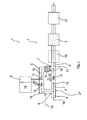
- FIG. 1 is shown schematically and merely by way of example a first embodiment of a regeneration device 1 according to the invention for a arranged in the exhaust line 2 of an internal combustion engine, not shown here particulate filter 3.
- the exhaust line 2 here has a raw gas line 21 with a first line section 4, from the upstream of the particulate filter 3 a feed line 5 branches off at a branch point 6, this supply line 5 also turn upstream of the particulate filter 3 at an outlet point 7 with the downstream of the branch point 6 continued line section 4 'is merged to form the power section 4 ".
- an HC oxidation catalyst 8 is arranged in the supply line 5.
- the regeneration device 1 comprises a metering device 9 for fuel, which, as is shown very schematically, is coupled to a control and / or regulating device 10.
- the metering device 9 has a running in the manner of a bypass line, projecting into the feed line 5 injection nozzle 11 through which the fuel 12 controlled or regulated with the control and / or regulating device 10 at predetermined times in predetermined amounts in the supply line 5 upstream of the HC oxidation catalyst 8 is injected.
- a throttle valve 13 is further arranged, which is preferably also coupled to the control and / or regulating device 10. Further, in the line section 4 'in the region between the branch point 6 and the point of discharge 7, a throttle valve 14 is likewise arranged, which is preferably also coupled to the control and / or regulating device 10.
- the raw gas flow 15 coming from the internal combustion engine 15 can be controlled or regulated in a controlled manner into the supply line 5 and mass of an exhaust gas flow 16 to be heated.
- the arrows 22 represent here schematically the variable adjustment of the throttle valve 13, 14 represents.
- the exhaust gas stream 16 to be heated takes along its flow path upstream of the HC oxidation catalyst 8 the injected fuel or the injected hydrocarbons and flows through fuel enriched the HC oxidation catalyst 8, in which then an exothermic reaction or oxidation takes place, due to the exhaust gas stream 16 a predetermined temperature is heated.
- This heated exhaust gas stream 16 ' is then fed back downstream of the HC oxidation catalyst 8 at the discharge point 7 to the raw gas stream 15' flowing via the line section 4, where the two exhaust gas streams 15 ', 16' mix, so that subsequently, after mixing two exhaust gas streams 15 ', 16', a hot Rohabgasstrom 17 flows to the particle filter 3, where the carbonaceous particles stored in the particulate filter 3 are converted to CO, CO 2 , N 2 and NO, whereby the particulate filter 3 is regenerated.
- the throttle valve 13 is controlled so that it substantially completely closes the supply line 5, so that no or virtually no exhaust gas flow reaches the particle filter 3 via the feed line 5. In this case, then the throttle valve 14 is fully open.
- the throttle valve 13 is opened so far that a predetermined amount of exhaust gas is diverted from the raw exhaust stream 15 and in the manner already described above, a hot Rohabgasstrom 17 is generated, which is then fed to the particulate filter 3 to its regeneration.
- the throttle valve 14 may be more or less closed and the Throttle valve 13 are opened, whereby the Rohabgasstrom 15 'is strongly throttled by the line section 4', so that a larger amount of exhaust gas 16 and thus a larger amount of oxygen via the supply line 5 and thus via the HC oxidation catalyst 8 to the particle filter 3 flows.
- a charge air side fresh air flow are mixed into the heated exhaust gas stream 16 to the heating power at predetermined times or when reaching predetermined exhaust gas flow temperatures and / or falls below a predetermined lambda value or oxygen value Raise the available amount of oxygen further increase.
- the particulate filter 3 is also followed by a NO x reduction catalyst 23, for example an SCR catalytic converter.
- a NO x reduction catalyst 23 for example an SCR catalytic converter.
- a further HC oxidation catalyst 18 may be provided by means of the high hydrocarbon concentrations downstream of the particulate filter 3 can be reliably avoided.
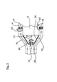
- Fig. 2 is shown schematically and by way of example a second embodiment of a regeneration device 1 according to the invention, in which arranged for a particularly compact and thus space-saving construction of the HC oxidation catalyst 8 within a HC-oxidation catalyst 8 annular Umhabgastechnischs Kunststoffes and recorded.
- the raw exhaust gas stream 15 flowing through a first line section 4 of the raw exhaust gas line 21 in the direction of the HC oxidation catalyst is here through one or more flow guide elements 24 into a first exhaust gas flow 15 'flowing through only the line section 4' of the raw exhaust gas line 21 and into one Oxidation catalyst 8 by flowing, to be heated second exhaust gas stream 16 divided.
- the raw exhaust gas stream 15 flowing through a first line section 4 of the raw exhaust gas line 21 in the direction of the HC oxidation catalyst is here through one or more flow guide elements 24 into a first exhaust gas flow 15 'flowing through only the line section 4' of the raw exhaust gas line 21 and into one Oxidation catalyst 8 by flowing, to be heated second exhaust
- the mass of the second exhaust gas flow 16 flowing through the HC oxidation catalytic converter 8 is thus predetermined by the geometry of the flow guide elements 24 and / or by the position of the throttle valve 13 mounted thereon, for example.
- the control of the throttle valve 13 is again via the electronic control and / or regulating device 10, in dependence on predetermined regeneration or operating parameters, analogous to previously in connection with the embodiments of Fig. 1 described control of the throttle valve 13th
- an injection nozzle 11 of a metering device 9 can be injected by the fuel 12 into the second exhaust gas stream 14, so that takes place in the HC oxidation catalyst 8, an exothermic reaction and the HC oxidation catalyst leaving hot exhaust gas stream 16 'is mixed together with the raw exhaust gas stream 15' to a hot exhaust gas stream 17.
- This hot exhaust gas stream 17 then flows through the particulate filter 3 and then through a NO x reduction catalyst 23, as previously described in connection with the Fig. 1 has been described.
- the flow regions formed by the flow guide elements 24 then form analogously to the embodiments according to FIGS FIGS. 1 and 2 in turn, a branched off from the line section 4 line section 4 'and a "supply line” 5, which are then brought together in the region downstream of the HC oxidation catalyst 8 again to a common line section 4 ".
- throttle valve (s) 14 may be provided by means of which the annulus geometry is more or less closable.
- the selected representation of two throttle valves 14 does not take into account this annular space geometry and serves only for the schematic representation.
Abstract
Description
Die Erfindung betrifft ein Verfahren zur Regeneration eines im Abgasstrang einer Brennkraftmaschine angeordneten Partikelfilters nach dem Oberbegriff des Anspruchs 1 sowie eine Vorrichtung zur Regeneration eines im Abgasstrang einer Brennkraftmaschine angeordneten Partikelfilters nach dem Oberbegriff des Anspruchs 8.The invention relates to a method for regeneration of a particle filter arranged in the exhaust line of an internal combustion engine according to the preamble of claim 1 and to a device for regeneration of a particle filter arranged in the exhaust line of an internal combustion engine according to the preamble of
Insbesondere betrifft die Erfindung ein Verfahren und eine Vorrichtung zur Regeneration von Partikelfiltern bei mit Luftüberschuss betriebenen Brennkraftmaschinen, wie beispielsweise Dieselmotoren oder Benzinmotoren mit Direkteinspritzung, wie sie in Nutzfahrzeugen oder Kraftfahrzeugen zum Einsatz gelangen.In particular, the invention relates to a method and apparatus for regeneration of particulate filters in super-powered internal combustion engines, such as diesel engines or direct-injection gasoline engines, such as those found in commercial vehicles or motor vehicles.
Zur Minimierung der Feinstoffpartikel werden in Fahrzeugen regelmäßig sogenannte Partikelabscheider oder Partikelfilter eingesetzt. Eine Partikelabscheider-Anordnung in Fahrzeugen ist beispielsweise aus der
Bei beiden vorstehend beschriebenen Anordnungen oxidiert jeweils ein stromauf des Partikelabscheiders bzw. des Partikelfilters angeordneter Oxidationskatalysator das Stickstoffmonoxid (NO) im Abgas mit Hilfe des ebenfalls enthaltenen Restsauerstoffes (O2) zu Stickstoffdioxid (NO2), und zwar gemäß folgender Gleichung:
2 NO + O2 ↔ 2 NO2
In both arrangements described above, an oxidation catalyst arranged upstream of the particle separator or of the particle filter oxidizes the nitrogen monoxide (NO) in the exhaust gas with the help of the likewise contained residual oxygen (O 2 ) to nitrogen dioxide (NO 2 ) according to the following equation:
2 NO + O 2 ↔ 2 NO 2
Das NO2 setzt sich im Partikelfilter zur Regeneration desselben mit den kohlenstoffhaltigen Feststoffpartikeln zu CO, CO2, N2 und NO um. Mit Hilfe des starken Oxidationsmittels NO2 kann somit eine kontinuierliche Entfernung der angelagerten Feinstoffpartikel erfolgen (passive Regeneration). Allerdings weist diese Vorrichtung und Verfahrensführung den Nachteil auf, dass hier eine große Menge an toxischem NO2 im Abgastrakt gebildet bzw. vorhanden ist.The NO 2 is converted to CO, CO 2 , N 2 and NO in the particulate filter for the regeneration thereof with the carbonaceous solid particles. With the help of the strong oxidizing agent NO 2 can thus be a continuous removal of the deposited fine particles (passive regeneration). However, this device and process management has the disadvantage that here a large amount of toxic NO 2 is formed or present in the exhaust gas tract.
Um ein Austreten von NO2 in die Umwelt zu vermeiden, ist daher darauf zu achten, dass der Bereich zwischen den NO-Oxidationskatalysatoren und den Partikelfiltern ausreichend dicht ausgeführt ist. Neben dem NO2 wird bei dieser Verfahrensführung an den platinhaltigen NO-Oxidationskatalysatoren aber auch SO3 aus im Kraftstoff- und/oder Motorenöl enthaltenem Schwefel gebildet. Dieses SO3 und das NO2 kondensieren an kalten Stellen im Abgastrakt zu hochkorrosiver Schwefel- bzw. Salpetersäure, so dass die Abgasanlage bis zu den Partikelfiltern in Edelstahl ausgeführt werden muss, um eine Korrosion zuverlässig zu vermeiden.In order to avoid leakage of NO 2 into the environment, care must therefore be taken that the area between the NO oxidation catalysts and the particulate filters is sufficiently dense. In addition to NO 2 , SO 3 from sulfur contained in the fuel and / or engine oil is also formed in this process procedure on the platinum-containing NO oxidation catalysts. This SO 3 and the NO 2 condense at cold spots in the exhaust tract To highly corrosive sulfuric or nitric acid, so that the exhaust system must be performed to the particulate filters in stainless steel to reliably prevent corrosion.
Des Weiteren ist es bekannt, eine Partikelfilterregeneration durch aktive Anhebung der Abgastemperatur durchzuführen. Hierzu beschreibt beispielsweise die
Durch diese Betriebsweise wird der Abgasmassenstrom durch den Dieselpartikelfilter während dessen Regenerationsphase verringert, so dass nur die Temperatur einer geringeren Abgasmenge angehoben werden muss und der Dieselpartikelfilter mit einer geringeren Energiezufuhr regeneriert werden kann. Zusätzlich soll durch die Aufteilung des Abgasmassenstroms und die nachfolgende Mischung des eine hohe Temperatur aufweisenden Abgasstroms des Hauptabgasstrangs und des eine niedrige Temperatur aufweisenden Abgasstroms des Nebenabgasstrangs am Mischpunkt die Temperatur des Abgasstroms durch den SCR-Katalysator wiederum reduziert werden können. Durch den Partikelabscheider im Nebenabgasstrang soll zudem verhindert werden, dass ein Abgasstrom ohne Rußpartikelabscheidung aus dem Abgasstrang austreten kann.By this operation, the exhaust gas mass flow through the diesel particulate filter is reduced during its regeneration phase, so that only the temperature of a smaller amount of exhaust gas must be increased and the diesel particulate filter can be regenerated with a lower power supply. In addition to be divided by the exhaust gas mass flow and the subsequent mixing of the high temperature exhaust stream of the main exhaust line and the low temperature exhaust stream of the Nebenabgasstrangs at the mixing point the temperature of the exhaust gas flow through the SCR catalyst can be reduced again. The particle separator in the secondary exhaust gas train is also intended to prevent an exhaust gas stream from escaping from the exhaust gas line without soot particle separation.
Die Zugabe der Kohlenwasserstoffe (HC) zu den Oxidationskatalysatoren erfolgt durch eine, diesen unmittelbar vorgeschaltete Injektionsvorrichtung. Da die Oxidationskatalysatoren bei einem derartigen Aufbau auch im Nicht-Regenerationsbetrieb NO zu NO2 oxidieren, findet auch im Nicht-Regenerationsbetrieb eine, wenngleich auch geringe passive Filterregeneration mit Hilfe von NO2 statt. Das heißt, dass es bei einem derartigen Aufbau auch im Nicht-Regenerationsbetrieb zu einer Bildung von NO2 kommt, das dann in der Regel unverbraucht emittiert wird. Aufgrund der Toxizität des NO2 ist dies jedoch unpraktikabel und unerwünscht.The addition of the hydrocarbons (HC) to the oxidation catalysts is carried out by a, this immediately upstream injection device. Since the oxidation catalysts in such a structure also oxidize NO to NO 2 in the non-regeneration mode, even if the regeneration mode is non-regenerative one, albeit small, passive filter regeneration takes place with the aid of NO 2 . That is, with such a structure, even in the non-regeneration mode, formation of NO 2 occurs, which is then usually emitted unconsumed. However, due to the toxicity of NO 2 , this is impractical and undesirable.
Ersichtlich ist ein derartiger Aufbau relativ bauteilintensiv und zudem wenig kompakt, so dass sich ein insgesamt großes Bauvolumen ergibt.As can be seen, such a construction is relatively component-intensive and, moreover, not very compact, resulting in an overall large volume of construction.
Es ist daher Aufgabe der vorliegenden Erfindung, ein Verfahren und eine Vorrichtung zur Regeneration eines im Abgasstrang einer Brennkraftmaschine angeordneten Partikelfilters zur Verfügung zu stellen, mittels dem bzw. mittels der auf baulich einfache Weise eine funktionssichere und zuverlässige Partikelfilter-Regeneration, insbesondere unter Minimierung der NO2- und/oder der SO3-Emissionen, möglich wird.It is therefore an object of the present invention to provide a method and a device for regenerating a particle filter arranged in the exhaust line of an internal combustion engine by means of or by means of a structurally simple manner a functionally reliable and reliable particulate filter regeneration, in particular while minimizing the NO 2 - and / or the SO 3 emissions, is possible.
Diese Aufgabe wird bezüglich des Verfahrens gelöst mit den Merkmalen des Anspruchs 1. Bezüglich der Vorrichtung wird diese Aufgabe gelöst mit den Merkmalen des Anspruchs 8. Vorteilhafte Ausgestaltungen hierzu sind jeweils Gegenstand der darauf rückbezogenen Unteransprüche.This object is achieved with respect to the method with the features of claim 1. Regarding the device, this object is achieved with the Features of
Erfindungsgemäß wird vorgeschlagen, dass der dem wenigstens einen Partikelfilter zugeführte Abgasstrom ein Rohabgasstrom der Brennkraftmaschine ist, dem während eines Regenerationsbetriebes stromauf des Partikelfilters ein gegenüber diesem Rohabgasstrom eine vorgegebene höhere Temperatur aufweisender heißer Abgasstrom beigemischt wird und zwar gesteuert mittels einer eine Drossel- und/oder Absperreinrichtung entsprechend vorgegebener Regenerationsparameter ansteuernden Steuer- und/oder Regeleinrichtung. Der Rohabgasstrom wird dabei in einer Rohabgasleitung geführt, dem stromauf des Partikelfilters mittels einer weiteren Abgasleitung, die hier als Zuführleitung bezeichnet wird, der heiße Abgasstrom zugeführt wird.According to the invention, it is proposed that the exhaust stream supplied to the at least one particulate filter is a raw exhaust stream of the internal combustion engine, which is admixed with a hot exhaust gas stream having a predetermined higher temperature during a regeneration operation upstream of the particulate filter, controlled by means of a throttling and / or shut-off device according to predetermined regeneration parameters controlling control and / or regulating device. The crude gas stream is guided in a raw exhaust gas line, which is fed to the upstream side of the particulate filter by means of a further exhaust gas line, which is referred to here as a supply line, the hot exhaust gas stream.
Unter einem Rohabgasstrom wird dabei im Sinne der vorliegenden Erfindung insbesondere ein Abgasstrom verstanden, der stromauf des Partikelfilters keinen NO-Oxidationskatalysator durchströmt und somit ein mit Rußpartikeln beladener, im Wesentlichen NO2-freier bzw. lediglich eine geringe Menge an NO2 aus der Verbrennung aufweisender Abgasstrom ist.In the context of the present invention, a raw exhaust gas stream is understood to mean, in particular, an exhaust gas stream which flows through no NO oxidation catalyst upstream of the particle filter and thus contains a NO 2 -free or only a small amount of NO 2 from the combustion laden with soot particles Exhaust gas flow is.
Gemäß einer besonders bevorzugten konkreten Ausgestaltung wird der zu erhitzende Abgasstrom stromauf des wenigstens einen Partikelfilters an einer Abzweigstelle von dem Rohabgasstrom abgezweigt, wobei dieser abgezweigte Abgasstrom dann mittels einer Heizeinrichtung, bevorzugt mittels wenigstens eines Heizkörperkatalysators erhitzt und dem Rohabgasstrom mittels der Zuführleitung stromab der Abzweigstelle und stromauf des wenigstens einen Partikelfilters an einer Mündungsstelle als erhitzter Abgasstrom wieder zugeführt wird.According to a particularly preferred specific embodiment, the exhaust gas stream to be heated is branched off upstream of the at least one particulate filter at a branch point from the Rohhabgasstrom, this branched exhaust gas stream then heated by means of a heater, preferably by means of at least one radiator catalyst and the Rohhabgasstrom means of the supply downstream of the branching and upstream the at least one particulate filter is supplied again at a point of discharge as a heated exhaust gas flow.
Mit einer derartigen erfindungsgemäßen Lösung lässt sich eine funktionssichere und zuverlässige Partikelfilterregeneration unter Minimierung der NO2-und/oder der SO3-Emissionen ohne den Einsatz von dem wenigstens einen Partikelfilter vorgeschalteten NO-Oxidationskatalysatoren bewerkstelligen. Dies geschieht insbesondere dadurch, dass die im Nichtregenerationsbetrieb über die Zuführleitung abgezweigte Abgasmenge auf einen vorgegebenen Wert minimiert wird, insbesondere auch jeglicher Abgasstrom über die Zuführleitung im Wesentlichen verhindert wird. Dadurch wird eine Bildung von NO2 und SO3 durch Oxidation von NO und SO2 an der bevorzugt als HC-Oxidationskatalysator ausgebildeten Heizeinrichtung vermieden bzw. verringert.With such a solution according to the invention, a functionally reliable and reliable particulate filter regeneration can be achieved while minimizing NO 2 and / or SO 3 emissions without the use of NO oxidation catalysts arranged upstream of the at least one particulate filter. This happens in particular in that the exhaust gas quantity branched off via the supply line in the non-regeneration mode is minimized to a predetermined value, in particular also any exhaust gas flow via the supply line is substantially prevented. This prevents or reduces the formation of NO 2 and SO 3 by oxidation of NO and SO 2 on the heating device, which is preferably designed as an HC oxidation catalyst.
Für die Regenerationsphase des Partikelfilters kann andererseits die über die Zuführleitung abgezweigte bzw. geleitete Abgasmenge durch Freigabe bzw. Öffnen der wenigstens einen Drossel- und/oder Absperreinrichtung auf einen vorgegebenen Mengenwert erhöht werden und können dann die Kohlenwasserstoffe dosiert zugegeben werden. In dieser Regenerationsphase ist keine Bildung von NO2 und SO3 zu erwarten, da einerseits deren katalytische Bildung unter der Anwesenheit von Kohlenwasserstoffen unterdrückt wird und andererseits die thermodynamischen NO/NO2- und SO2/SO3-Gleichgewichte bei den während der Regeneration an der bevorzugt als HC-Oxidationskatalysator ausgebildeten Heizeinrichtung auftretenden Temperaturen von zum Beispiel über 700°C auf der Seite von NO und SO2 liegen, das heißt, dass die Bildung von NO2 und SO3 dann in diesem Fall rein thermodynamisch begrenzt bzw. verhindert wird. Durch die exotherme Reaktion bzw. Oxidation der bevorzugt Kohlenwasserstoffe gelingt im Anschluss eine effektive und optimale thermische Regeneration der am nachgeschalteten Partikelfilter abgeschiedenen kohlenstoffhaltigen Rußpartikel.For the regeneration phase of the particulate filter, on the other hand, the exhaust gas branched off or led via the supply line can be increased to a predetermined value by releasing or opening the at least one throttling and / or shut-off device and then the hydrocarbons can be metered in added. No formation of NO 2 and SO 3 is to be expected in this regeneration phase, since on the one hand their catalytic formation under the presence of hydrocarbons is suppressed and, on the other hand, the thermodynamic NO / NO 2 and SO 2 / SO 3 equilibria during the regeneration the preferably occurring as a HC-oxidation catalyst heater formed temperatures of, for example, about 700 ° C on the side of NO and SO 2 , that is, the formation of NO 2 and SO 3 then limited in this case purely thermodynamically or prevented , As a result of the exothermic reaction or oxidation of the preferred hydrocarbons, effective and optimal thermal regeneration of the carbon-containing soot particles deposited on the downstream particle filter succeeds.
Wie bereits zuvor dargelegt, wird somit bei der vorliegenden Erfindungsidee der heiße Abgasstrom bevorzugt mittels wenigstens eines Heizkatalysators erzeugt, der in der Zuführleitung angeordnet ist. Dieser Heizkatalysator ist bevorzugt als Oxidationskatalysator ausgebildet, insbesondere als HC-Oxidationskatalysator. Diesem Oxidationskatalysator werden stromauf desselben Kohlenwasserstoffe zugeführt. Bei den zugeführten Kohlenwasserstoffen handelt es sich vorzugsweise um Kraftstoff aus dem Kraftstoffsystem des Fahrzeugs, der mittels der Zudosiereinrichtung, beispielsweise über eine Düse oder dergleichen, feinstverteilt bzw. zerstäubt in die Zuführleitung stromauf des Heiz- bzw. Oxidationskatalysators zu vorgegebenen Zeiten in einer vorgegebenen Menge zugedüst wird. Ein derartiger Heiz- bzw. Oxidationskatalysator weist bevorzugt eine solche Aktivkomponente auf, die mit vorgegebenen Bestandteilen eines Abgasstroms, das heißt im vorliegenden Beispielfall mit den Kohlenwasserstoffen, durch exotherme Reaktion einen erhitzten Abgasstrom erzeugt. Besonders geeignet sind für einen HC-Oxidationskatalysator die Elemente der Platinmetallgruppe und/oder Vanadium und/oder Wolfram und/oder Cer als Aktivkomponente. Diese Aktivkomponenten können sowohl einzeln als auch in Kombination untereinander eingesetzt bzw. verwendet werden.As already stated above, in the present invention idea, therefore, the hot exhaust gas flow is preferably generated by means of at least one heating catalytic converter, which is arranged in the supply line. This heating catalyst is preferably designed as an oxidation catalyst, in particular as an HC oxidation catalyst. These oxidation catalyst are fed upstream of the same hydrocarbons. The supplied hydrocarbons are preferably fuel from the fuel system of the vehicle, which by means of the metering device, for example via a nozzle or the like, finely distributed or atomized into the supply line upstream of the heating or oxidation catalyst at predetermined times zugedüst in a predetermined amount becomes. Such a heating or oxidation catalyst preferably has such an active component which, with predetermined constituents of an exhaust gas stream, that is to say in the present example case with the hydrocarbons, generates a heated exhaust gas stream by exothermic reaction. Particularly suitable for an HC oxidation catalyst are the elements of the platinum metal group and / or vanadium and / or tungsten and / or cerium as the active component. These active components can be used or used both individually and in combination with each other.
Konkret kann die Steuer- und/oder Regeleinrichtung eine Drossel- und/oder Absperreinrichtung ansteuern, die zum Beispiel durch wenigstens eine Drossel- und/oder Absperrklappe oder ein Drossel- und/oder Absperrventil gebildet ist. Derartige Klappen- oder Ventilelemente sind einfach und funktionssicher anzusteuern und zu bedienen, wobei diese bevorzugt im Rohabgasstrom nach der Abzweigstelle und vor der Mündungsstelle bzw. im abgezweigten Abgasstrom stromauf des Heizkatalysators angeordnet sind.Specifically, the control and / or regulating device can control a throttle and / or shut-off device, which is formed, for example, by at least one throttle and / or shut-off valve or a throttle and / or shut-off valve. Such flap or valve elements are simple and reliable to control and operate, which are preferably arranged in the raw gas flow to the branching point and upstream of the discharge point or in the branched off exhaust stream upstream of the heating catalyst.
Zum Zünden der zudosierten Kohlenwasserstoffe wird der zu erhitzende Abgasstrom über die bevorzugt als HC-Oxidationskatalysator ausgebildete Heizeinrichtung geführt, wodurch der Abgasstrom erhitzt wird. Die dadurch zu erzielende Heizleistung ist allerdings durch die vorhandene Sauerstoffmenge limitiert. Denn für den Fall, dass durch die Zugabe von zu Großen Mengen an Kohlenwasserstoffen der Lambdawert den Wert 1 erreichen sollte, ist keine Oxidation der Kohlenwasserstoffe mehr möglich. Um dies zu vermeiden, wird vorgeschlagen, dem zu erhitzenden Abgasstrom, nach Erreichen einer bestimmten vorgegebenen Temperatur und/oder Unterschreiten bzw. Erreichen eines bestimmten vorgegebenen Lambda- bzw. Sauerstoffwerts, Frischluft zuzuführen. Diese optionale Frischluftzuführung bewirkt ein Anheben des Lambdawertes und damit auch eine Anhebung der maximal möglichen Heizleistung. Die Frischluft kann dabei generell ladeluftseitig abgezweigt werden, konkret zum Beispiel auch stromab einer Einmündung einer Abgasrückführleitung in eine Ladeluftleitung.To ignite the added hydrocarbons, the exhaust gas flow to be heated is formed via the hydrocarbon, which is preferably formed as an HC oxidation catalyst Heating device out, whereby the exhaust gas stream is heated. However, the heating power to be achieved is limited by the amount of oxygen present. Because in the event that the lambda value should reach the value 1 due to the addition of too large quantities of hydrocarbons, oxidation of the hydrocarbons is no longer possible. To avoid this, it is proposed to supply fresh air to the exhaust gas flow to be heated after reaching a certain predetermined temperature and / or falling below or reaching a certain predetermined lambda or oxygen value. This optional fresh air supply causes a raising of the lambda value and thus an increase of the maximum possible heat output. In this case, the fresh air can generally be branched off on the charge air side, in particular, for example, downstream of a junction of an exhaust gas recirculation line into a charge air line.
Durch die Zugabe von zum Beispiel Kohlenwasserstoffen bzw. in dessen Folge, durch deren Oxidation am HC-Oxidationskatalysator, kann der Restsauerstoffgehalt somit im zu erhitzenden bzw. erhitzten Abgasstrom sehr stark abnehmen, so dass gegebenenfalls keine vollständige Oxidation der Kohlenwasserstoffe mehr gelingt. Um dies zu verhindern, kann der Rohabgasstrom alternativ oder zusätzlich stromab der Abzweigstelle, aber stromauf der Mündungsstelle, zum Beispiel gedrosselt werden, wodurch dann wieder mehr Abgas und damit mehr Sauerstoff über die Zuführleitung geleitet wird. Dazu kann im Bereich der Zuführleitung stromab und/oder stromauf des Heizkatalysators wenigstens ein Sauerstoffsensor vorgesehen sein, mittels dem die Sauerstoffkonzentration im Abgasstrom erfasst werden kann. Ebenso kann dort aber auch wenigstens ein Temperatursensor vorgesehen sein.By adding, for example, hydrocarbons or as a consequence thereof, by their oxidation on the HC oxidation catalyst, the residual oxygen content can thus decrease very sharply in the exhaust gas flow to be heated or heated so that complete oxidation of the hydrocarbons may no longer succeed. In order to prevent this, the crude exhaust gas stream can alternatively or additionally be throttled downstream of the branching point, but upstream of the discharge point, for example, whereby more exhaust gas and thus more oxygen are then passed through the supply line again. For this purpose, at least one oxygen sensor can be provided in the region of the supply line downstream and / or upstream of the heating catalytic converter, by means of which the oxygen concentration in the exhaust gas flow can be detected. Likewise, however, at least one temperature sensor can also be provided there.
Der Heizkatalysator kann grundsätzlich auch außerhalb des Abgasstrangs angeordnet sein, was gegebenenfalls jedoch zu einer raschen Auskühlung dieses Heizkatalysators führen kann. Gemäß einer bevorzugten Ausgestaltung ist daher vorgesehen, den Heizkatalysator so im Abgasstrang anzuordnen, dass dieser von wenigstens einem Abgasstrom, insbesondere vom Rohabgasstrom, wenigstens bereichsweise umströmt wird. In diesem Fall sind dann die über die Rohabgasleitung und die Zuführleitung geführten Abgasströme strömungstechnisch entkoppelt.The heating catalytic converter can in principle also be arranged outside the exhaust gas line, which, however, if appropriate, can lead to a rapid cooling of this heating catalytic converter. According to a preferred embodiment is therefore intended to arrange the heating catalyst in the exhaust line, that it is at least partially flowed around by at least one exhaust gas stream, in particular from the raw gas stream. In this case, the exhaust gas streams conducted via the raw exhaust gas line and the supply line are then decoupled fluidically.
Um zum Beispiel im Falle von Kohlenwasserstoffen als Oxidationsmittel hohe Kohlenwasserstoffkonzentrationen stromab des Partikelfilters zu vermeiden, kann dieser mit einem Katalysator zur Oxidation von Kohlenwasserstoffen versehen werden. Auch ein stromab und/oder stromauf des Partikelfilters, nach der Mündungsstelle, angebrachter Katalysator mit Kohlenwasserstoffoxidationsaktivität ist denkbar. Um unnötig hohe NO2- und SO3-Emissionen zu vermeiden, ist die Beladung dieser zusätzlichen Katalysatoren mit Aktivkomponenten und/oder deren Volumen, im Vergleich zu dem wenigstens einen in der Zuführleitung angeordneten Heizkatalysator geringer.For example, in the case of hydrocarbons as the oxidizing agent to avoid high hydrocarbon concentrations downstream of the particulate filter, this can be provided with a catalyst for the oxidation of hydrocarbons. It is also conceivable to use a catalyst having hydrocarbon oxidation activity downstream of and / or upstream of the particulate filter, downstream of the particulate filter. In order to avoid unnecessarily high NO 2 and SO 3 emissions, the loading of these additional catalysts with active components and / or their volume is lower compared to the at least one heating catalyst arranged in the feed line.
Das gesamte System kann mit weiteren Katalysatoren zur NOX-Reduktion, wie beispielsweise NOX-Speicherkatalysatoren und/oder SCR-Katalysatoren, kombiniert werden, die bevorzugt stromab des Partikelfilters im Abgasstrang vorgesehen bzw. angeordnet sein können. Für die NOX-Speicherkatalysatoren werden Platin und/oder Barium und/oder Calcium als Aktivkomponenten bevorzugt. Demgegenüber ist für die SCR-Katalysatoren der Einsatz von wolframoxidstabilisiertem Vanadiumpentoxid auf Titandioxidbasis oder Eisen-Zeolithe oder Kupfer-Zeolithe oder Kobalt-Zeolithe sinnvoll.The entire system may be combined with other catalysts for NO x reduction, such as NO x storage catalysts and / or SCR catalysts, which may preferably be provided downstream of the particulate filter in the exhaust line. For the NO x storage catalysts platinum and / or barium and / or calcium are preferred as active components. In contrast, the use of tungsten oxide-stabilized vanadium pentoxide based on titanium dioxide or iron zeolites or copper zeolites or cobalt zeolites makes sense for the SCR catalysts.
Grundsätzlich kann die Aktivität sämtlicher Katalysatoren durch den Einsatz von Zeolithen erhöht werden.In principle, the activity of all catalysts can be increased by the use of zeolites.
Grundsätzlich kann der wenigstens eine bevorzugt als HC-Oxidationskatalysator ausgebildete Heizkatalysator auch zusätzlich mit einer NO-Oxidationsaktivität versehen sein, wodurch die NO2-Anteile im Nicht-Regenerationsbetrieb angehoben werden, so dass in vorgegebenen Grenzen zusätzlich eine grundsätzlich Regenerationsmöglichkeit des Partikelfilters mit Hilfe von NO2 ermöglicht wird. Die hier gegebenenfalls gebildeten NO2-Mengen sind jedoch deutlich geringer als dies beim Einsatz von dem Partikelfilter vorgeschalteten NO-Oxidationskatalysatoren der Fall wäre. Allerdings ist dann in diesem Zusammenhang weiter darauf zu achten, dass der HC-Oxidationskatalysator thermisch stabil ausgeführt sein muss. Dies hat wiederum üblicherweise eine geringere NO-Oxidationsaktivität im Vergleich zu reinen NO-Oxidationskatalysatoren zur Folge, so dass auch aus diesem Grunde die NO-Menge reduziert bleibt.In principle, the at least one heating catalyst, which is preferably designed as an HC oxidation catalyst, can also additionally have a NO oxidation activity be provided, whereby the NO 2 levels are raised in the non-regeneration operation, so that in addition a basically regeneration possibility of the particulate filter with the aid of NO 2 is made possible within predetermined limits. However, the amounts of NO 2 which are optionally formed here are significantly lower than would be the case when using NO oxidation catalysts arranged upstream of the particle filter. However, it must then be ensured in this connection that the HC oxidation catalyst must be thermally stable. This in turn usually results in a lower NO oxidation activity in comparison to pure NO oxidation catalysts, so that also for this reason, the amount of NO remains reduced.
Die Erfindung wird nachfolgend anhand einer Zeichnung näher erläutert.The invention will be explained in more detail with reference to a drawing.
Es zeigen:
- Fig. 1
- schematisch eine erste erfindungsgemäße Ausführungsform
- Fig. 2
- schematisch eine zur
Fig. 1 alternative Ausführungsform mit innerhalb des Abgasstromes angeordnetem HC-Oxidations- katalysator, und - Fig. 3
- schematisch eine vergrößerte Detailansicht des sich verzweigen- den Rohrleitungsabschnittes.
- Fig. 1
- schematically a first embodiment of the invention
- Fig. 2
- schematically a to
Fig. 1 alternative embodiment with disposed within the exhaust stream HC oxidation catalyst, and - Fig. 3
- schematically an enlarged detail view of the branching pipe section.
In der
Konkret weist der Abgasstrang 2 hier eine Rohabgasleitung 21 mit einem ersten Leitungsabschnitt 4 auf, von dem stromauf des Partikelfilters 3 eine Zuführleitung 5 an einer Abzweigstelle 6 abzweigt, wobei diese Zuführleitung 5 ebenfalls wiederum stromauf des Partikelfilters 3 an einer Mündungsstelle 7 mit dem stromab der Abzweigstelle 6 weitergeführten Leitungsabschnitt 4' zusammengeführt wird, um den Leistungsabschnitt 4" auszubilden.Specifically, the exhaust line 2 here has a
In der Zuführleitung 5 ist ein HC-Oxidationskatalysator 8 angeordnet.In the
Ferner umfasst die Regenerationsvorrichtung 1 eine Zudosiervorrichtung 9 für Kraftstoff, die, wie dies äußerst schematisch dargestellt ist, mit einer Steuer- und/oder Regeleinrichtung 10 gekoppelt ist. Die Zudosiervorrichtung 9 weist eine in die in der Art einer Bypassleitung ausgeführte, in die Zuführleitung 5 einragende Einspritzdüse 11 auf, über die der Kraftstoff 12 gesteuert bzw. geregelt mit der Steuer- und/oder Regeleinrichtung 10 zu vorgegebenen Zeiten in vorgegebenen Mengen in die Zuführleitung 5 stromauf des HC-Oxidationskatalysators 8 eingedüst wird.Furthermore, the regeneration device 1 comprises a
Wie dies der
Je nach der Stellung der beiden Drosselklappen 13, 14 kann die von einem von der Brennkraftmaschine kommenden Rohabgasstrom 15 in die Zuführleitung 5 abgezweigte Menge und Masse eines zu erhitzenden Abgasstroms 16 gesteuert vorgegeben bzw. geregelt werden. In der
Der zu erhitzende Abgasstrom 16 nimmt entlang seines Strömungsweges stromauf des HC-Oxidationskatalysators 8 den eingedüsten Kraftstoff bzw. die eingedüsten Kohlenwasserstoffe auf und durchströmt kraftstoffangereichert den HC-Oxidationskatalysator 8, in dem dann eine exotherme Reaktion bzw. Oxidation stattfindet, aufgrund der der Abgasstrom 16 auf eine vorgegebene Temperatur erhitzt wird.The
Dieser erhitzte Abgasstrom 16' wird dann stromab des HC-Oxidationskatalysators 8 an der Mündungsstelle 7 wieder dem über den Leitungsabschnitt 4' strömenden Rohabgasstrom 15' zugeführt, wo sich die beiden Abgasströme 15', 16' vermischen, so dass anschließend, nach dem Vermischen der beiden Abgasströme 15', 16', ein heißer Rohabgasstrom 17 zum Partikelfilter 3 strömt, wo die im Partikelfilter 3 eingelagerten kohlenstoffhaltigen Rußpartikel zu CO, CO2, N2 und NO umgesetzt werden, wodurch der Partikelfilter 3 regeneriert wird.This heated exhaust gas stream 16 'is then fed back downstream of the
Im Nicht-Regenerationsbetrieb wird die Drosselklappe 13 so angesteuert, dass diese die Zuführleitung 5 im Wesentlichen vollständig verschließt, so dass kein bzw. nahezu kein Abgasstrom über die Zuführleitung 5 zum Partikelfilter 3 gelangt. In diesem Fall ist dann die Drosselklappe 14 vollständig geöffnet.In the non-regeneration mode, the
Im Regenerationsbetrieb dagegen ist die Drosselklappe 13 so weit geöffnet, dass eine vorgegebene Abgasmenge vom Rohabgasstrom 15 abgezweigt wird und in der bereits zuvor bereits beschriebenen Weise ein heißer Rohabgasstrom 17 erzeugt wird, der dann dem Partikelfilter 3 zu dessen Regeneration zugeführt wird.In contrast, in the regeneration mode, the
Für den Fall, dass zum Beispiel durch die Zugabe des Kraftstoffes 12 in der Zuführleitung 5 der Restsauerstoffgehalt im Abgasstrom 16 zu stark abnehmen sollte und damit keine vollständige Oxidation der Kohlenwasserstoffe am HC-Oxidationskatalysator 8 erfolgt, kann die Drosselklappe 14 mehr oder weniger geschlossen und die Drosselklappe 13 geöffnet werden, wodurch der Rohabgasstrom 15' durch den Leitungsabschnitt 4' stark gedrosselt wird, so dass eine größere Abgasmenge 16 und damit eine größere Sauerstoffmenge über die Zuführleitung 5 und damit über den HC-Oxidationskatalysator 8 zum Partikelfilter 3 strömt.In the event that, for example, by the addition of the
Ebenso kann, wie durch die strichliert eingezeichnete Frischluftleitung 19 symbolisiert, während des Regenerationsbetriebes ein ladeluftseitiger Frischluftstrom in den zu erhitzenden Abgasstrom 16 eingemischt werden, um die Heizleistung zu vorgegebenen Zeiten bzw. bei Erreichen vorgegebener Abgasstromtemperaturen und/oder Unterschreiten eines vorgegebenen Lambdawerts bzw. Sauerstoffwerts durch Anheben der zur Verfügung stehenden Sauerstoffmenge nochmals weiter zu erhöhen.Likewise, as symbolized by the dashed lines drawn
Im vorliegenden Beispielfall ist dem Partikelfilter 3 zudem noch ein NOX-Reduktionskatalysator 23, zum Beispiel ein SCR-Katalysator, nachgeschaltet.In the present example, the
Des Weiteren kann, wie dies in der
In der
Die Masse des durch den HC-Oxidationskatalysator 8 strömenden zweiten Abgasstroms 16 wird somit durch die Geometrie der Strömungsleitelemente 24 und/oder durch die Stellung der zum Beispiel an dieser gelagerten Drosselklappe 13 vorgegeben. Die Ansteuerung der Drosselklappe 13 erfolgt wiederum über die elektronische Steuer- und/oder Regeleinrichtung 10, und zwar in Abhängigkeit von vorgegebenen Regenerations- bzw. Betriebsparametern, analog zur zuvor in Verbindung mit den Ausgestaltungen der
Unmittelbar vor der Mündungsöffnung 20 der Strömungsleitelemente 24 ist hier wiederum eine Einspritzdüse 11 einer Zudosiereinrichtung 9 angeordnet, mittels der Kraftstoff 12 in den zweiten Abgasstrom 14 eingedüst werden kann, so dass im HC-Oxidationskatalysator 8 eine exotherme Reaktion stattfindet und ein den HC-Oxidationskatalysator 8 verlassender heißer Abgasstrom 16' zusammen mit dem Rohabgasstrom 15' zu einem heißen Abgasstrom 17 vermischt wird. Dieser heiße Abgasstrom 17 strömt dann durch den Partikelfilter 3 sowie anschließend durch einen NOx-Reduktionskatalysator 23, wie dies bereits zuvor in Verbindung mit der
Die durch die Strömungsleitelemente 24 ausgebildeten Strömungsbereiche bilden hier dann analog zu den Ausgestaltungen nach den
Im Bereich der Leitungsabschnitte 4' können dann analog zur Ausgestaltung der
Claims (15)
Priority Applications (1)
| Application Number | Priority Date | Filing Date | Title |
|---|---|---|---|
| EP09012063.5A EP2305978B1 (en) | 2009-09-23 | 2009-09-23 | Method and device for regenerating a particulate filter built into the exhaust gas flow of a combustion engine |
Applications Claiming Priority (1)
| Application Number | Priority Date | Filing Date | Title |
|---|---|---|---|
| EP09012063.5A EP2305978B1 (en) | 2009-09-23 | 2009-09-23 | Method and device for regenerating a particulate filter built into the exhaust gas flow of a combustion engine |
Publications (2)
| Publication Number | Publication Date |
|---|---|
| EP2305978A1 true EP2305978A1 (en) | 2011-04-06 |
| EP2305978B1 EP2305978B1 (en) | 2016-11-16 |
Family
ID=41668210
Family Applications (1)
| Application Number | Title | Priority Date | Filing Date |
|---|---|---|---|
| EP09012063.5A Active EP2305978B1 (en) | 2009-09-23 | 2009-09-23 | Method and device for regenerating a particulate filter built into the exhaust gas flow of a combustion engine |
Country Status (1)
| Country | Link |
|---|---|
| EP (1) | EP2305978B1 (en) |
Cited By (5)
| Publication number | Priority date | Publication date | Assignee | Title |
|---|---|---|---|---|
| WO2012130789A1 (en) * | 2011-03-28 | 2012-10-04 | Hjs Emission Technology Gmbh & Co. Kg | Method for feeding thermal energy into an exhaust emission control unit connected in the exhaust gas system of an internal combustion engine |
| WO2013104633A1 (en) * | 2012-01-09 | 2013-07-18 | Eminox Limited | Exhaust system and method for reducing particulate and no2 emissions |
| EP2693011A1 (en) * | 2012-07-30 | 2014-02-05 | Benteler Automobiltechnik GmbH | Exhaust gas valve assembly with integrated bypass |
| CN105003326A (en) * | 2015-07-28 | 2015-10-28 | 青岛双瑞海洋环境工程股份有限公司 | Marine exhaust denitration system |
| CN106677861A (en) * | 2015-07-08 | 2017-05-17 | 保时捷股份公司 | Particle filter for motor vehicle |
Citations (8)
| Publication number | Priority date | Publication date | Assignee | Title |
|---|---|---|---|---|
| EP0341832A2 (en) | 1988-05-13 | 1989-11-15 | Johnson Matthey Inc. | Treatment of diesel exhaust gas |
| EP1072765A2 (en) | 1999-07-26 | 2001-01-31 | Man Nutzfahrzeuge Ag | Method and apparatus for separating fine particulate matter from exhaust gas of internal combustion engine |
| DE10043613A1 (en) * | 2000-08-02 | 2002-02-14 | Fev Motorentech Gmbh | Filter arrangement, used for cleaning exhaust gases from IC engines, comprises porous particle filter body having catalytically active coating, oxidation catalyst, and adjusting element for adjusting feeds |
| WO2006104240A1 (en) * | 2005-03-28 | 2006-10-05 | Toyota Jidosha Kabushiki Kaisha | Exhaust gas purifying system of internal combustion engine |
| DE102005055240A1 (en) | 2005-11-19 | 2007-05-31 | Daimlerchrysler Ag | Exhaust gas after-treatment device for e.g. diesel engine, has after-treatment unit to retain and oxidize sooty particles from gas stream, and throttle valve arranged in auxiliary exhaust gas system for regulating proportion of stream |
| DE102007033424A1 (en) * | 2007-07-18 | 2009-01-22 | Man Nutzfahrzeuge Ag | Self-cleaning exhaust aftertreatment system |
| FR2924749A1 (en) * | 2007-12-10 | 2009-06-12 | Peugeot Citroen Automobiles Sa | Exhaust gas line for e.g. diesel engine, of motor vehicle, has valves and conduit that are controlled by logic controller to bypass part of gaseous flow containing quantity of fuel directed on catalyst, without passing via another catalyst |
| EP2154344A2 (en) * | 2008-08-12 | 2010-02-17 | MAN Nutzfahrzeuge AG | Method and device for regenerating a particulate filter built into the exhaust gas tract of a combustion engine |
-
2009
- 2009-09-23 EP EP09012063.5A patent/EP2305978B1/en active Active
Patent Citations (8)
| Publication number | Priority date | Publication date | Assignee | Title |
|---|---|---|---|---|
| EP0341832A2 (en) | 1988-05-13 | 1989-11-15 | Johnson Matthey Inc. | Treatment of diesel exhaust gas |
| EP1072765A2 (en) | 1999-07-26 | 2001-01-31 | Man Nutzfahrzeuge Ag | Method and apparatus for separating fine particulate matter from exhaust gas of internal combustion engine |
| DE10043613A1 (en) * | 2000-08-02 | 2002-02-14 | Fev Motorentech Gmbh | Filter arrangement, used for cleaning exhaust gases from IC engines, comprises porous particle filter body having catalytically active coating, oxidation catalyst, and adjusting element for adjusting feeds |
| WO2006104240A1 (en) * | 2005-03-28 | 2006-10-05 | Toyota Jidosha Kabushiki Kaisha | Exhaust gas purifying system of internal combustion engine |
| DE102005055240A1 (en) | 2005-11-19 | 2007-05-31 | Daimlerchrysler Ag | Exhaust gas after-treatment device for e.g. diesel engine, has after-treatment unit to retain and oxidize sooty particles from gas stream, and throttle valve arranged in auxiliary exhaust gas system for regulating proportion of stream |
| DE102007033424A1 (en) * | 2007-07-18 | 2009-01-22 | Man Nutzfahrzeuge Ag | Self-cleaning exhaust aftertreatment system |
| FR2924749A1 (en) * | 2007-12-10 | 2009-06-12 | Peugeot Citroen Automobiles Sa | Exhaust gas line for e.g. diesel engine, of motor vehicle, has valves and conduit that are controlled by logic controller to bypass part of gaseous flow containing quantity of fuel directed on catalyst, without passing via another catalyst |
| EP2154344A2 (en) * | 2008-08-12 | 2010-02-17 | MAN Nutzfahrzeuge AG | Method and device for regenerating a particulate filter built into the exhaust gas tract of a combustion engine |
Cited By (8)
| Publication number | Priority date | Publication date | Assignee | Title |
|---|---|---|---|---|
| WO2012130789A1 (en) * | 2011-03-28 | 2012-10-04 | Hjs Emission Technology Gmbh & Co. Kg | Method for feeding thermal energy into an exhaust emission control unit connected in the exhaust gas system of an internal combustion engine |
| US8904764B2 (en) | 2011-03-28 | 2014-12-09 | Hjs Emission Technology Gmbh & Co. Kg | Method for feeding thermal energy into an exhaust emission control unit connected in the exhaust gas system of an internal combustion engine |
| RU2592362C2 (en) * | 2011-03-28 | 2016-07-20 | ХЙС ЭМИШН ТЕКНОЛОДЖИ ГМБХ унд КО. КГ | Method for supply of heat energy to exhaust gas neutralisation device arranged in outlet path of internal combustion engine |
| WO2013104633A1 (en) * | 2012-01-09 | 2013-07-18 | Eminox Limited | Exhaust system and method for reducing particulate and no2 emissions |
| EP2693011A1 (en) * | 2012-07-30 | 2014-02-05 | Benteler Automobiltechnik GmbH | Exhaust gas valve assembly with integrated bypass |
| CN106677861A (en) * | 2015-07-08 | 2017-05-17 | 保时捷股份公司 | Particle filter for motor vehicle |
| CN106677861B (en) * | 2015-07-08 | 2020-03-10 | 保时捷股份公司 | Particle filter for a motor vehicle |
| CN105003326A (en) * | 2015-07-28 | 2015-10-28 | 青岛双瑞海洋环境工程股份有限公司 | Marine exhaust denitration system |
Also Published As
| Publication number | Publication date |
|---|---|
| EP2305978B1 (en) | 2016-11-16 |
Similar Documents
| Publication | Publication Date | Title |
|---|---|---|
| EP2154345B1 (en) | Method and device for regenerating a particulate filter built into the exhaust gas line of a combustion engine | |
| DE102008038719A1 (en) | Method and device for regenerating a particle filter arranged in the exhaust gas line of an internal combustion engine | |
| EP2154344B1 (en) | Method and device for regenerating a particulate filter built into the exhaust gas tract of a combustion engine | |
| EP2379851B1 (en) | Device and method for regenerating a particulate filter arranged in the exhaust section of an internal combustion engine | |
| EP2075050B1 (en) | Method and apparatus for improving the hydrolysis of a reducing agent in a waste gas treatment system | |
| EP1892395B1 (en) | Exhaust gas treatment system | |
| EP1771644B1 (en) | Exhaust gas system, in particular for the internal combustion engine of a motor vehicle | |
| EP1892394B1 (en) | Exhaust gas aftertreatment system | |
| EP1900916B1 (en) | Exhaust gas aftertreatment system | |
| EP2452055B1 (en) | Method and apparatus to regenerate a particle filter in an exhaust gas line of a combustion engine | |
| EP2198134B1 (en) | Method for reducing emission of nitrogen oxide in a motor vehicle having an internal combustion lean operating engine | |
| EP2743470B1 (en) | Method and apparatus for raising the exhaust gas temperature in the exhaust pipe of a turbocharged internal combustion engine | |
| EP2376749B1 (en) | Method for operating for exhaust gas after-treatment components and exhaust gas after-treatment device | |
| EP2305978B1 (en) | Method and device for regenerating a particulate filter built into the exhaust gas flow of a combustion engine | |
| DE19955324A1 (en) | Device and method for reducing harmful components in the exhaust gas of an internal combustion engine, in particular a diesel internal combustion engine | |
| WO2009065555A1 (en) | Exhaust gas after-treatment device for an internal combustion engine and method for the after-treatment of exhaust gases of an internal combustion engine | |
| DE102009004416A1 (en) | Method for operating components of internal combustion engine for exhaust gas after-treatment, involves extracting exhaust gas partial stream from exhaust gas main stream upstream exhaust gas turbine | |
| WO2010070100A1 (en) | Exhaust gas cleaning system and method for operating an exhaust gas cleaning system | |
| EP2169192B1 (en) | Device and method for spraying fuel into the exhaust gas flow of an internal combustion engine, in particular for regenerating a particulate filter | |
| DE102005038187A1 (en) | Exhaust gas cleaning device for lean-burn engines comprises a catalyst for removing nitrogen oxides from an internal combustion engine exhaust gas stream which is guided in a first partial system and in a second connected partial system | |
| DE102009005733A1 (en) | Device for regenerating particle filter in exhaust manifold of e.g. diesel engine of passenger vehicle, has nitrogen monoxide- and hydrocarbon-oxidation catalyst provided upstream of particle filter | |
| DE102014008056B4 (en) | Method for operating an exhaust system of an internal combustion engine, in particular for a motor vehicle | |
| DE102006043151A1 (en) | Regeneration device for particle filter has reducer generating system including valve system via which hydrogen- or carbon-monoxide-rich mixture is supplied | |
| DE102004062897A1 (en) | Exhaust gas treatment system for internal combustion engine has at least one time switched device to collect carbon-oxygen compounds before converter | |
| AT521310A1 (en) | METHOD FOR CONTROLLING AN EXHAUST AFTER TREATMENT SYSTEM |
Legal Events
| Date | Code | Title | Description |
|---|---|---|---|
| PUAI | Public reference made under article 153(3) epc to a published international application that has entered the european phase |
Free format text: ORIGINAL CODE: 0009012 |
|
| 17P | Request for examination filed |
Effective date: 20100317 |
|
| AK | Designated contracting states |
Kind code of ref document: A1 Designated state(s): AT BE BG CH CY CZ DE DK EE ES FI FR GB GR HR HU IE IS IT LI LT LU LV MC MK MT NL NO PL PT RO SE SI SK SM TR |
|
| AX | Request for extension of the european patent |
Extension state: AL BA RS |
|
| RIN1 | Information on inventor provided before grant (corrected) |
Inventor name: DOERING, ANDREAS |
|
| RIC1 | Information provided on ipc code assigned before grant |
Ipc: F01N 9/00 20060101ALI20160531BHEP Ipc: F01N 3/023 20060101ALI20160531BHEP Ipc: F01N 13/00 20100101ALI20160531BHEP Ipc: F01N 3/035 20060101ALI20160531BHEP Ipc: F01N 3/20 20060101ALI20160531BHEP Ipc: F01N 3/025 20060101AFI20160531BHEP |
|
| GRAP | Despatch of communication of intention to grant a patent |
Free format text: ORIGINAL CODE: EPIDOSNIGR1 |
|
| INTG | Intention to grant announced |
Effective date: 20160714 |
|
| GRAS | Grant fee paid |
Free format text: ORIGINAL CODE: EPIDOSNIGR3 |
|
| GRAA | (expected) grant |
Free format text: ORIGINAL CODE: 0009210 |
|
| RBV | Designated contracting states (corrected) |
Designated state(s): AT BE BG CH CY CZ DK EE ES FI FR GB GR HR HU IE IS IT LI LT LU LV MC MK MT NL NO PL PT RO SE SI SK SM TR |
|
| REG | Reference to a national code |
Ref country code: DE Ref legal event code: R108 |
|
| AK | Designated contracting states |
Kind code of ref document: B1 Designated state(s): AT BE BG CH CY CZ DK EE ES FI FR GB GR HR HU IE IS IT LI LT LU LV MC MK MT NL NO PL PT RO SE SI SK SM TR |
|
| REG | Reference to a national code |
Ref country code: GB Ref legal event code: FG4D Free format text: NOT ENGLISH |
|
| REG | Reference to a national code |
Ref country code: CH Ref legal event code: EP |
|
| REG | Reference to a national code |
Ref country code: IE Ref legal event code: FG4D Free format text: LANGUAGE OF EP DOCUMENT: GERMAN |
|
| REG | Reference to a national code |
Ref country code: AT Ref legal event code: REF Ref document number: 846167 Country of ref document: AT Kind code of ref document: T Effective date: 20161215 |
|
| REG | Reference to a national code |
Ref country code: SE Ref legal event code: TRGR |
|
| REG | Reference to a national code |
Ref country code: NL Ref legal event code: FP |
|
| PG25 | Lapsed in a contracting state [announced via postgrant information from national office to epo] |
Ref country code: LV Free format text: LAPSE BECAUSE OF FAILURE TO SUBMIT A TRANSLATION OF THE DESCRIPTION OR TO PAY THE FEE WITHIN THE PRESCRIBED TIME-LIMIT Effective date: 20161116 |
|
| REG | Reference to a national code |
Ref country code: LT Ref legal event code: MG4D |
|
| PG25 | Lapsed in a contracting state [announced via postgrant information from national office to epo] |
Ref country code: NO Free format text: LAPSE BECAUSE OF FAILURE TO SUBMIT A TRANSLATION OF THE DESCRIPTION OR TO PAY THE FEE WITHIN THE PRESCRIBED TIME-LIMIT Effective date: 20170216 Ref country code: LT Free format text: LAPSE BECAUSE OF FAILURE TO SUBMIT A TRANSLATION OF THE DESCRIPTION OR TO PAY THE FEE WITHIN THE PRESCRIBED TIME-LIMIT Effective date: 20161116 Ref country code: GR Free format text: LAPSE BECAUSE OF FAILURE TO SUBMIT A TRANSLATION OF THE DESCRIPTION OR TO PAY THE FEE WITHIN THE PRESCRIBED TIME-LIMIT Effective date: 20170217 |
|
| PG25 | Lapsed in a contracting state [announced via postgrant information from national office to epo] |
Ref country code: FI Free format text: LAPSE BECAUSE OF FAILURE TO SUBMIT A TRANSLATION OF THE DESCRIPTION OR TO PAY THE FEE WITHIN THE PRESCRIBED TIME-LIMIT Effective date: 20161116 Ref country code: PL Free format text: LAPSE BECAUSE OF FAILURE TO SUBMIT A TRANSLATION OF THE DESCRIPTION OR TO PAY THE FEE WITHIN THE PRESCRIBED TIME-LIMIT Effective date: 20161116 Ref country code: ES Free format text: LAPSE BECAUSE OF FAILURE TO SUBMIT A TRANSLATION OF THE DESCRIPTION OR TO PAY THE FEE WITHIN THE PRESCRIBED TIME-LIMIT Effective date: 20161116 Ref country code: PT Free format text: LAPSE BECAUSE OF FAILURE TO SUBMIT A TRANSLATION OF THE DESCRIPTION OR TO PAY THE FEE WITHIN THE PRESCRIBED TIME-LIMIT Effective date: 20170316 Ref country code: HR Free format text: LAPSE BECAUSE OF FAILURE TO SUBMIT A TRANSLATION OF THE DESCRIPTION OR TO PAY THE FEE WITHIN THE PRESCRIBED TIME-LIMIT Effective date: 20161116 |
|
| PG25 | Lapsed in a contracting state [announced via postgrant information from national office to epo] |
Ref country code: DK Free format text: LAPSE BECAUSE OF FAILURE TO SUBMIT A TRANSLATION OF THE DESCRIPTION OR TO PAY THE FEE WITHIN THE PRESCRIBED TIME-LIMIT Effective date: 20161116 Ref country code: EE Free format text: LAPSE BECAUSE OF FAILURE TO SUBMIT A TRANSLATION OF THE DESCRIPTION OR TO PAY THE FEE WITHIN THE PRESCRIBED TIME-LIMIT Effective date: 20161116 Ref country code: SK Free format text: LAPSE BECAUSE OF FAILURE TO SUBMIT A TRANSLATION OF THE DESCRIPTION OR TO PAY THE FEE WITHIN THE PRESCRIBED TIME-LIMIT Effective date: 20161116 Ref country code: RO Free format text: LAPSE BECAUSE OF FAILURE TO SUBMIT A TRANSLATION OF THE DESCRIPTION OR TO PAY THE FEE WITHIN THE PRESCRIBED TIME-LIMIT Effective date: 20161116 Ref country code: CZ Free format text: LAPSE BECAUSE OF FAILURE TO SUBMIT A TRANSLATION OF THE DESCRIPTION OR TO PAY THE FEE WITHIN THE PRESCRIBED TIME-LIMIT Effective date: 20161116 |
|
| PG25 | Lapsed in a contracting state [announced via postgrant information from national office to epo] |
Ref country code: SM Free format text: LAPSE BECAUSE OF FAILURE TO SUBMIT A TRANSLATION OF THE DESCRIPTION OR TO PAY THE FEE WITHIN THE PRESCRIBED TIME-LIMIT Effective date: 20161116 Ref country code: BG Free format text: LAPSE BECAUSE OF FAILURE TO SUBMIT A TRANSLATION OF THE DESCRIPTION OR TO PAY THE FEE WITHIN THE PRESCRIBED TIME-LIMIT Effective date: 20170216 |
|
| PLBE | No opposition filed within time limit |
Free format text: ORIGINAL CODE: 0009261 |
|
| STAA | Information on the status of an ep patent application or granted ep patent |
Free format text: STATUS: NO OPPOSITION FILED WITHIN TIME LIMIT |
|
| REG | Reference to a national code |
Ref country code: FR Ref legal event code: PLFP Year of fee payment: 9 |
|
| 26N | No opposition filed |
Effective date: 20170817 |
|
| PG25 | Lapsed in a contracting state [announced via postgrant information from national office to epo] |
Ref country code: SI Free format text: LAPSE BECAUSE OF FAILURE TO SUBMIT A TRANSLATION OF THE DESCRIPTION OR TO PAY THE FEE WITHIN THE PRESCRIBED TIME-LIMIT Effective date: 20161116 |
|
| REG | Reference to a national code |
Ref country code: CH Ref legal event code: PL |
|
| GBPC | Gb: european patent ceased through non-payment of renewal fee |
Effective date: 20170923 |
|
| PG25 | Lapsed in a contracting state [announced via postgrant information from national office to epo] |
Ref country code: MC Free format text: LAPSE BECAUSE OF FAILURE TO SUBMIT A TRANSLATION OF THE DESCRIPTION OR TO PAY THE FEE WITHIN THE PRESCRIBED TIME-LIMIT Effective date: 20161116 |
|
| REG | Reference to a national code |
Ref country code: IE Ref legal event code: MM4A |
|
| REG | Reference to a national code |
Ref country code: BE Ref legal event code: MM Effective date: 20170930 |
|
| PG25 | Lapsed in a contracting state [announced via postgrant information from national office to epo] |
Ref country code: LU Free format text: LAPSE BECAUSE OF NON-PAYMENT OF DUE FEES Effective date: 20170923 |
|
| PG25 | Lapsed in a contracting state [announced via postgrant information from national office to epo] |
Ref country code: GB Free format text: LAPSE BECAUSE OF NON-PAYMENT OF DUE FEES Effective date: 20170923 Ref country code: CH Free format text: LAPSE BECAUSE OF NON-PAYMENT OF DUE FEES Effective date: 20170930 Ref country code: LI Free format text: LAPSE BECAUSE OF NON-PAYMENT OF DUE FEES Effective date: 20170930 Ref country code: IE Free format text: LAPSE BECAUSE OF NON-PAYMENT OF DUE FEES Effective date: 20170923 |
|
| PG25 | Lapsed in a contracting state [announced via postgrant information from national office to epo] |
Ref country code: BE Free format text: LAPSE BECAUSE OF NON-PAYMENT OF DUE FEES Effective date: 20170930 |
|
| PG25 | Lapsed in a contracting state [announced via postgrant information from national office to epo] |
Ref country code: MT Free format text: LAPSE BECAUSE OF FAILURE TO SUBMIT A TRANSLATION OF THE DESCRIPTION OR TO PAY THE FEE WITHIN THE PRESCRIBED TIME-LIMIT Effective date: 20161116 |
|
| REG | Reference to a national code |
Ref country code: FR Ref legal event code: PLFP Year of fee payment: 10 |
|
| REG | Reference to a national code |
Ref country code: AT Ref legal event code: MM01 Ref document number: 846167 Country of ref document: AT Kind code of ref document: T Effective date: 20170923 |
|
| PG25 | Lapsed in a contracting state [announced via postgrant information from national office to epo] |
Ref country code: AT Free format text: LAPSE BECAUSE OF NON-PAYMENT OF DUE FEES Effective date: 20170923 |
|
| PG25 | Lapsed in a contracting state [announced via postgrant information from national office to epo] |
Ref country code: HU Free format text: LAPSE BECAUSE OF FAILURE TO SUBMIT A TRANSLATION OF THE DESCRIPTION OR TO PAY THE FEE WITHIN THE PRESCRIBED TIME-LIMIT; INVALID AB INITIO Effective date: 20090923 |
|
| PG25 | Lapsed in a contracting state [announced via postgrant information from national office to epo] |
Ref country code: CY Free format text: LAPSE BECAUSE OF NON-PAYMENT OF DUE FEES Effective date: 20161116 |
|
| PG25 | Lapsed in a contracting state [announced via postgrant information from national office to epo] |
Ref country code: MK Free format text: LAPSE BECAUSE OF FAILURE TO SUBMIT A TRANSLATION OF THE DESCRIPTION OR TO PAY THE FEE WITHIN THE PRESCRIBED TIME-LIMIT Effective date: 20161116 |
|
| PG25 | Lapsed in a contracting state [announced via postgrant information from national office to epo] |
Ref country code: TR Free format text: LAPSE BECAUSE OF FAILURE TO SUBMIT A TRANSLATION OF THE DESCRIPTION OR TO PAY THE FEE WITHIN THE PRESCRIBED TIME-LIMIT Effective date: 20161116 |
|
| PG25 | Lapsed in a contracting state [announced via postgrant information from national office to epo] |
Ref country code: IS Free format text: LAPSE BECAUSE OF FAILURE TO SUBMIT A TRANSLATION OF THE DESCRIPTION OR TO PAY THE FEE WITHIN THE PRESCRIBED TIME-LIMIT Effective date: 20170316 |
|
| PGFP | Annual fee paid to national office [announced via postgrant information from national office to epo] |
Ref country code: NL Payment date: 20230926 Year of fee payment: 15 Ref country code: IT Payment date: 20230920 Year of fee payment: 15 |
|
| PGFP | Annual fee paid to national office [announced via postgrant information from national office to epo] |
Ref country code: SE Payment date: 20230926 Year of fee payment: 15 Ref country code: FR Payment date: 20230926 Year of fee payment: 15 |