EP2304476B1 - Identifizierung von möglichen gefahrenmaterialien anhand aktiver elektromagnetischer wellen - Google Patents
Identifizierung von möglichen gefahrenmaterialien anhand aktiver elektromagnetischer wellen Download PDFInfo
- Publication number
- EP2304476B1 EP2304476B1 EP09773035.2A EP09773035A EP2304476B1 EP 2304476 B1 EP2304476 B1 EP 2304476B1 EP 09773035 A EP09773035 A EP 09773035A EP 2304476 B1 EP2304476 B1 EP 2304476B1
- Authority
- EP
- European Patent Office
- Prior art keywords
- processor
- imaging system
- radiation
- phase
- ray
- Prior art date
- Legal status (The legal status is an assumption and is not a legal conclusion. Google has not performed a legal analysis and makes no representation as to the accuracy of the status listed.)
- Active
Links
Images


Classifications
-
- G—PHYSICS
- G01—MEASURING; TESTING
- G01S—RADIO DIRECTION-FINDING; RADIO NAVIGATION; DETERMINING DISTANCE OR VELOCITY BY USE OF RADIO WAVES; LOCATING OR PRESENCE-DETECTING BY USE OF THE REFLECTION OR RERADIATION OF RADIO WAVES; ANALOGOUS ARRANGEMENTS USING OTHER WAVES
- G01S13/00—Systems using the reflection or reradiation of radio waves, e.g. radar systems; Analogous systems using reflection or reradiation of waves whose nature or wavelength is irrelevant or unspecified
- G01S13/88—Radar or analogous systems specially adapted for specific applications
- G01S13/887—Radar or analogous systems specially adapted for specific applications for detection of concealed objects, e.g. contraband or weapons
-
- G—PHYSICS
- G01—MEASURING; TESTING
- G01S—RADIO DIRECTION-FINDING; RADIO NAVIGATION; DETERMINING DISTANCE OR VELOCITY BY USE OF RADIO WAVES; LOCATING OR PRESENCE-DETECTING BY USE OF THE REFLECTION OR RERADIATION OF RADIO WAVES; ANALOGOUS ARRANGEMENTS USING OTHER WAVES
- G01S7/00—Details of systems according to groups G01S13/00, G01S15/00, G01S17/00
- G01S7/02—Details of systems according to groups G01S13/00, G01S15/00, G01S17/00 of systems according to group G01S13/00
- G01S7/41—Details of systems according to groups G01S13/00, G01S15/00, G01S17/00 of systems according to group G01S13/00 using analysis of echo signal for target characterisation; Target signature; Target cross-section
- G01S7/411—Identification of targets based on measurements of radar reflectivity
- G01S7/412—Identification of targets based on measurements of radar reflectivity based on a comparison between measured values and known or stored values
-
- G—PHYSICS
- G01—MEASURING; TESTING
- G01V—GEOPHYSICS; GRAVITATIONAL MEASUREMENTS; DETECTING MASSES OR OBJECTS; TAGS
- G01V8/00—Prospecting or detecting by optical means
- G01V8/005—Prospecting or detecting by optical means operating with millimetre waves, e.g. measuring the black losey radiation
Definitions
- the invention relates to imaging systems for identification of concealed items, for example imaging systems for security scanning. It applies to imaging systems which operate over any of a wide range of frequencies.
- WO200875948 describes analysis of imaging radiation to visualize properties of the human internal body, such as electrical conductivity, electric permittivity, and magnetic permeability. Non-coherent waves having a large bandwidth are transmitted, to ensure that they are harmless. The bandwidth is preferably half of a control frequency.
- the radiation source may for example be a broadband non-coherent noise generator.
- US7304306 describes an imaging system using terahertz radiation, and a direct conversion detector module is used. Detected radiation is split into several components, which are attenuated. The objective is to detect explosive material. The different signals are combined to provide a composite signal.
- US7295019 describes use of capacitive and inductance sensors for detecting concealed items such as plastic explosives and ceramic knives.
- WO2006/067773 (Farran ) describes detection using a filter for partitioning bands.
- GB2424531 (Agilent) describes use of antenna elements programmed with phase delays.
- the invention is directed towards providing for improved detection of non-metallic concealed items, particularly with improved differentiation between threat and non-threat items.
- An imaging system is as set out in claim 1.
- said frequency is in the range of 1 GHz to 300GHz.
- said frequency is in the range of 1 GHz to 80GHz.
- the processor is adapted to classify materials based on a database of relative permittivities, and said database includes permittivity data or relative permittivity data for specified threat materials such as explosives or narcotics.
- the system is adapted to detect radiation from two or more volume elements, a volume element providing reference data if it does not include the concealed material.
- the processor is adapted to process amplitude and phase contrast from element to element in the scan volume to generate an image of the scan volume.
- different amplitude and phase responses for the elements are used by the processor to detect the location and the orientation of a concealed material.
- the transmitter and the receiver comprise a horn in a confocal arrangement, in which the horn illuminates the reflect array and the reflect array is configured to focus the radiation at an element in the scan volume, and the reflections are in turn refocused by the reflect array at the horn aperture, and the processor is adapted to control the reflect array to scan the focal point throughout the scan volume in a systematic way, and to use horn pattern and the scan strategy to compute the geometry associated with each volume clement in terms of individual rays, and in which amplitude and phase variations between the object and the surrounding volume and the computed geometry are used to estimate the relative permittivity.
- each transmitted ray data for two returned rays is processed by the processor, in which a first ray is reflected off the surface of the object and a second ray is transmitted through the object and reflected at an interface between the object and the body, and in which the processor is adapted to perform an estimation process which tracks both rays and identifies the following events:
- the processor is adapted to execute algorithms implementing Snell's law coupled to the electromagnetic properties of fields in the vicinity of boundaries to compute amplitude as a level of attenuation, and phase, ⁇ model and ⁇ model , of received radiation.
- the processor is adapted to execute algorithms reflecting the electromagnetic properties of wave impedance and reflection coefficient in the vicinity of boundaries to compute amplitude as a level of attenuation, and phase, ⁇ model and ⁇ model , of received radiation.
- the processor is adapted to execute confocal image theory algorithms to compute amplitude as a level of attenuation and phase, ⁇ model and ⁇ model , of received radiation.
- the system further comprises a reflector for reflecting scattered radiation, and the receiver is mounted to receive radiation after being reflected.
- the reflect array is configured to focus the transmitted radiation at successive elements in the scan volume.
- the transmitter and the receiver comprise a horn antenna
- the system comprises a reflect array arranged in tiles, each tile consisting of an array of patch antennas with switching transistors and an associated controller for controlling the transistors, and in which the controller is adapted to configure phases of the patch antennas to achieve a particular pattern in space when the array is illuminated by the horn antenna, in which the processor is adapted to:
- a transistor is selected to add 0 or 180 degree phase shift depending on the calculated phase by turning it on and 0 degrees by turning it off, scanning being implemented over the volume by applying appropriate patterns of switching the transistors.
- the invention involves using different views taken using active microwave imaging hardware, and automatically classifying a material carried on the human body as safe or as a potential threat material.
- the automatic classification is based on the fact that the human body has a much higher reflectivity (as its permittivity is much higher) than many dielectric materials such as explosives or narcotic potential threat materials.
- a and “an” can mean “one or more than one.” For example, if a device is described as having a feature X, the device may have one or more of feature X.
- microwave imaging system enables the detection of concealed threats on the human body, due to penetration of microwaves through materials.
- microwave in this context refers to electromagnetic radiation in the frequency range of 1 to 300GHz.
- An imaging system can use any non-ionizing radiation, including but not limited to millimetre wave or terahertz radiation.
- the system uses millimetre wave illumination to image an object.
- the incident beam can be focused using the reflect array.
- the reflect array can be arranged in tiles. Each tile can consist of an array of patch antennas with switching FETs and the associated electronics for controlling the FETs. Each panel constitutes a reflect array.
- the phases of the individual patches can be configured to achieve a particular pattern in space when the array is illuminated by a horn antenna. The distance from the horn to a patch and the distance from the patch to the focal point can be calculated and summed. The resulting distance can then be converted into wavelengths at the operating frequency.
- the fractional portion of the distance can be converted into phase by multiplying by 360 degrees.
- the phases resulting from the above calculation should be identical or substantially identical. It is possible to approximate this by having the phases agree by better than 180 degrees.
- the FETs can be selected to add 0 or 180 degree phase shift depending on the calculated phase.
- a FET can be configured to deliver a phase shift of 180 degrees by turning it on and 0 degrees by turning it off. Thus, scanning can be implemented over a volume by applying appropriate patterns of ones and zeroes to the FETs.
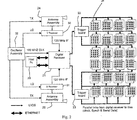
- the imaging system is in one embodiment a real-time imaging system having a controller 20 which is responsible for all decision-making.
- the controller 20 controls display of the images and a graphical user interface.
- a digital receiver 21 can control the panels through trigger boards 22 and 23. Received radiation responses are via horn antenna circuits 24 and 25.
- the PC 20 connects to the digital receiver 21 using two Ethernet links. All PC instructions can be sent via the digital receiver 21 and all responses from the system are returned to the PC 20 via the digital receiver 21.
- the daisy-chain interconnection from the digital receiver 21 to the tiles 26 allows communication of general instructions and data, such as write instructions, uploading reflector switch patterns and diagnostics. In general, the daisy-chain links can be used for bi-directional communication.
- Fig. 2 shows trigger boards 22 and 23 and parallel links between them and each tile. These parallel links provide scan block addresses and synchronisation signals. Power is also supplied to the tiles 26 via the trigger boards 22 and 23.
- the radiation frequency used in one embodiment is 24.12 GHz. It has been found that a frequency range of 1GHz to 80GHz is particularly effective in some embodiments, and that a sub-range of 1GHz to 40GHz is particularly effective. However, it is envisaged that different wavelengths may be employed in other embodiments, up to 300GHz.
- An active microwave imaging system illuminates a predefined scan volume, and measures both the amplitude and phase of the received signal from each volume element in the scan volume. The amplitude and phase contrast from element to element is used to generate an image of the scan volume.
- the amplitude and phase of the received signal are functions of the geometry of the imaging rays, the geometry of the object, and the dielectric properties of the object. Analysis of amplitude and phase data allows computation of these object properties.
- the dielectric permittivity can be deduced from incident, reflected, and transmitted electromagnetic waves.
- the reflection and transmission of electromagnetic waves or rays are functions of the geometry, the surface texture and the wave impedance on both sides of the object interface.
- the wave impedance is dependent on the permeability and permittivity of the material. For most materials of concern permeability is not a differentiator and therefore can be ignored.
- the dielectric properties are related to the intrinsic material properties and state of the object.
- the permittivity can be used to classify the material.
- the scan geometry is based on a confocal system where a horn illuminates a reflect array and the reflect array is configured to focus the radiation at an element in the scan volume. The reflections are in turn refocused by a reflect array at the horn aperture.
- the reflect array is electronically configured to scan the focal point throughout the scan volume in a systematic way. Knowledge of the horn pattern and the scan strategy allows the system to compute the geometry associated with each volume element. This is often referred to as "ray tracing". Amplitude and phase variations between the object and the surrounding volume and the computed geometry are used to estimate the relative permittivity and thus facilitate categorization of the object using a database of material relative permittivities.
- Figs. 3 and 4 illustrate the geometry used in the estimation process.
- Fig. 3 is a case where the body is imaged and
- Fig. 4 is a case where a concealed object located on the body is detected and the relative permittivity of the object is estimated. All rays originating at the horn and terminating at the horn are used in the estimation process.
- the estimate of relative permittivity is based on the change in attenuation and phase delay between the situations in Figs.3 and 4 .
- the attenuation and phase delay are extracted from image data. These are then written in terms of the unknowns - relative permittivity, and object thickness. The resulting equations are solved to arrive at an estimate of relative permittivity and object thickness.
- each incident ray generates an associated Ray 1 and Ray 2.
- the estimation process implemented by the imaging system accounts for all incident rays originating at the horn.
- Object detection software processes the image to identify objects on the body and the material classification software automatically reports an estimate of relative permittivity and its classification.
- the detection software uses edges in the images to identify anomalies.
- the material categorisation process can also be user-driven, an operator selecting a concealed object in the image and then selecting a nearby part of the body to use as a reference for the measurement.
- a ray Ep, with amplitude unity is emitted from the horn towards the patch p.
- the ray after reflection from the object is directed to patch q whose position is known using geometrical optics.
- the ray reflected from patch q is directed towards the horn.
- ⁇ q is the reflection coefficient related to reflection from the body and ⁇ q is the total electrical path length.
- the ray after being reflected by both the object and the body generates two rays, one is directed towards patch q1 and the other towards patch q2.
- the positions of patches q1 and q2 are known using geometrical optics.
- Gp, Gq1 and Gq2 are the horn gains at the patches p, q1 and q2.
- ⁇ q1 and ⁇ q2 are the reflection coefficients related to the object and body respectively.
- ⁇ q1 and ⁇ q2 are the respective electrical path lengths.
- the relative permittivity ⁇ r , and object thickness T are chosen to ensure a best fit of computed ⁇ model and ⁇ model to measured ⁇ and ⁇ .
- the calculation depicts the changing wave impedance and reflection coefficient when a wave flows from the horn to the target and back to the horn. It also uses the electromagnetic properties of wave impedance and reflection coefficient in the vicinity of boundaries.
- the transmitted beam is first computed, this then illuminates the body and threat resulting in a reflected beam.
- the reflected beam is in turn reflected from the panel to the horn.
- the signal received by the horn is used to compute the attenuation and phase shift between the transmitted and reflected signals, respectively ⁇ model and ⁇ model .
- the body can be modeled using a number of plates whose orientations are derived from the imaging data.
- the computation proceeds as normal except the computation of ⁇ model and ⁇ model takes account of the plates and their orientations.
- the body has a very high reflection index and therefore reflective plates are effective models.
- a 1m x 1m reflect array panel consisting of 15000 patches generates a Gaussian shaped beam.
- the wax is located 70cm in front of the imaging panel.
- the imaging spot step increment is 0.4cm horizontally, 0.4cm vertically and 1.25cm ahead.
- test points should lead to the right solution but, it is advisable to use multiple test points to find/confirm the appropriate dielectric permittivity and thickness.
- the invention provides the major advantage of utilising existing imaging system hardware to generate not only an image of the scan volume, but also an estimate of the permittivity of concealed objects.
- the system can suggest material identity based on the permittivity estimates.
Landscapes
- Engineering & Computer Science (AREA)
- Radar, Positioning & Navigation (AREA)
- Remote Sensing (AREA)
- Physics & Mathematics (AREA)
- General Physics & Mathematics (AREA)
- Computer Networks & Wireless Communication (AREA)
- Electromagnetism (AREA)
- Life Sciences & Earth Sciences (AREA)
- General Life Sciences & Earth Sciences (AREA)
- Geophysics (AREA)
- Radar Systems Or Details Thereof (AREA)
- Investigating Or Analysing Materials By Optical Means (AREA)
- Geophysics And Detection Of Objects (AREA)
- Aerials With Secondary Devices (AREA)
- Measurement Of Resistance Or Impedance (AREA)
Claims (15)
- Bildgebungssystem, das Folgendes umfasst:einen Sender (24) zum Richten von Strahlung auf ein Scan-Volumen, in dem sich ein Ziel befindet;einen Empfänger (21, 24) zum Empfangen gestreuter Strahlung von dem Volumen; undeinen Prozessor (20, 21) zum Verarbeiten der gestreuten Strahlung, um ein Bild gemäß der Amplitude und Phase der empfangenen Strahlung zu erzeugen;eine an den Prozessor gekoppelte Anzeigevorrichtung (20) zum Erzeugen einer Bildanzeige, wobeider Sender (24) dazu angepasst ist, die einfallende Strahlung mit einer im Wesentlichen einzigen Frequenz zu senden;das System dazu angepasst ist, ein verborgenes Material zu identifizieren;wobei der Prozessor (20) dazu angepasst ist, ein verborgenes dielektrisches Material gemäß der Permittivität relativ zu derjenigen des menschlichen Körpers zu klassieren, wobei die relative Permittivität aus den Amplituden- und Phaseninformationen in der empfangenen Strahlung hergeleitet wird;dadurch gekennzeichnet, dassdas System ein Reflexionsarray (26) zum Fokussieren von Strahlung des einfallenden Strahls umfasst und dass der Prozessor (20) dazu angepasst ist, Phase und Amplitude gestreuter Strahlung sowohl in der Nähe des verborgenen Materials als auch an dem verborgenen Material zu messen, wobei die in der Nähe des verborgenen Materials einen Bezug bereitstellt;das System dazu angepasst ist, Strahlung von zwei oder mehr Volumenelementen zu erfassen, wobei ein Volumenelement Bezugsdaten bereitstellt, wenn es das verborgene Material nicht enthält, undder Prozessor (20) dazu angepasst ist, Anomalien an Rändern in den aufgezeichneten Bildern automatisch zu identifizieren und die Anomalien beim Herleiten relativer Permittivitätsdaten zu verwenden.
- Bildgebungssystem nach Anspruch 1, wobei die Frequenz im Bereich von 1 GHz bis 300 GHz liegt.
- Bildgebungssystem nach Anspruch 2, wobei die Frequenz im Bereich von 1 GHz bis 80 GHz liegt.
- Bildgebungssystem nach einem der vorangehenden Ansprüche, wobei der Prozessor (20) dazu angepasst ist, Materialien basierend auf einer Datenbank relativier Permittivitäten zu klassieren, und die Datenbank Permittivitätsdaten oder relative Permittivitätsdaten für festgelegte Gefahrenmaterialien, wie etwa Sprengstoffe oder Rauschgift enthält.
- Bildgebungssystem nach einem der vorangehenden Ansprüche, wobei der Prozessor dazu angepasst ist, Amplituden- und Phasenkontrast von Element zu Element in dem Scan-Volumen zu verarbeiten, um ein Bild des Scanvolumens zu erzeugen.
- Bildgebungssystem nach Anspruch 5, wobei von dem Prozessor verschiedene Amplituden- und Phasenantworten für die Elemente verwendet werden, um die Lage und die Orientierung eines verborgenen Materials zu erfassen.
- Bildgebungssystem nach einem der vorangehenden Ansprüche, wobei der Sender und der Empfänger ein Horn (24) in einer konfokalen Anordnung umfassen, in der das Horn das Reflexionsarray (26) anstrahlt und das Reflexionsarray dazu konfiguriert ist, die Strahlung an einem Element in dem Scan-Volumen zu fokussieren, und die Reflexionen ihrerseits von dem Reflexionsarray an der Öffnung des Horns (24) neu fokussiert werden, und der Prozessor (20, 21) dazu angepasst ist, das Reflexionsarray zu steuern, um das gesamte Scan-Volumen auf systematische Weise mit dem Brennpunkt zu scannen und das Hommuster und die Scan-Strategie zu verwenden, um die mit jedem Volumenelement assoziierte Geometrie hinsichtlich einzelner Strahlen zu berechnen, und wobei Amplituden- und Phasenabweichungen zwischen dem Gegenstand und dem umgebenden Volumen und die berechnete Geometrie verwendet werden, um die relative Permittivität abzuschätzen.
- Bildgebungssystem nach Anspruch 7, wobei für jeden gesendeten Strahl Daten für zwei zurückgesendete Strahlen von dem Prozessor verarbeitet werden, wobei ein erster Strahl von der Oberfläche des Gegenstands reflektiert wird und ein zweite Strahl durch den Gegenstand hindurchgelassen wird und an einer Grenzfläche zwischen dem Gegenstand und dem Körper reflektiert wird, und wobei der Prozessor dazu angepasst ist, einen Abschätzungsprozess auszuführen, der beide Strahlen verfolgt und die folgenden Ereignisse identifiziert:keiner der Strahlen wird von dem Horn eingefangen und spielt daher in dem Abschätzungsprozess keine Rolle,der erste Strahl wird eingefangen und wird in dem Abschätzungsprozess berücksichtigt, aber der zweite Strahl geht verloren,der zweite Strahl wird eingefangen und wird in dem Abschätzungsprozess berücksichtigt, aber der erste Strahl geht verloren, undbeide Strahlen werden eingefangen und tragen beide zu dem Abschätzungsprozess bei.
- Bildgebungssystem nach einem der vorangehenden Ansprüche, wobei der Prozessor dazu angepasst ist, das Snelliussche Gesetz, gekoppelt an die elektromagnetischen Eigenschaften von Feldern im Bereich von Grenzen, implementierende Algorithmen auszuführen, um die Amplitude als einen Dämpfungsgrad, sowie Phase, τmodel und Φmodel, empfangener Strahlung zu berechnen.
- Bildgebungssystem nach einem der vorangehenden Ansprüche, wobei der Prozessor dazu angepasst ist, die elektromagnetischen Eigenschaften der Wellenimpedanz und des Reflexionskoeffizienten im Bereich von Grenzen wiedergebende Algorithmen auszuführen, um die Amplitude als einen Dämpfungsgrad, sowie Phase, τmodel und Φmodel, empfangener Strahlung zu berechnen.
- Bildgebungssystem nach einem der vorangehenden Ansprüche, wobei der Prozessor dazu angepasst ist, Konfokalbildtheoriealgorithmen auszuführen, um die Amplitude als einen Dämpfungsgrad sowie Phase, τmodel und Φmodel, empfangener Strahlung zu berechnen.
- Bildgebungssystem nach einem der vorangehenden Ansprüche, weiter umfassend einen Reflektor zum Reflektieren gestreuter Strahlung, wobei der Empfänger angebracht ist, um Strahlung zu empfangen, nachdem sie reflektiert wurde.
- Bildgebungssystem nach Anspruch 12, wobei das Reflexionsarray (26) dazu konfiguriert ist, die gesendete Strahlung an aufeinanderfolgenden Elementen in dem Scan-Volumen zu fokussieren.
- Bildgebungssystem nach einem der vorangehenden Ansprüche, wobei der Sender und der Empfänger eine Hornantenne (24) umfassen, wobei das Reflexionsarray (26) in Kacheln angeordnet ist, wobei jede Kachel aus einem Array von Patch-Antennen mit Schalttransistoren und einem zugehörigen Kontroller zum Steuern der Transistoren besteht, und wobei der Kontroller dazu angepasst ist, Phasen der Patch-Antennen dazu zu konfigurieren, ein bestimmtes Muster im Raum zu erreichen, wenn das Array von der Hornantenne angestrahlt wird, wobei der Prozessor dazu angepasst ist:die Entfernung von der Hornantenne zu einem Patch und die Entfernung von dem Patch zu dem Brennpunkt zu berechnen und zu summieren,die Entfernung in Wellenlängen bei der Betriebsfrequenz umzuwandeln, unddurch Multiplizieren mit einer Zahl von Graden einen Bruchteil der Entfernung in die Phase umzuwandeln, und wobei, damit jeder Patch konstruktiv zu dem Fokus beiträgt, die Phasen im Wesentlichen identisch sein müssen.
- Bildgebungssystem nach Anspruch 14, wobei ein Transistor ausgewählt ist, um abhängig von der berechneten Phase eine Phasenverschiebung von 0 oder 180 Grad, indem er eingeschaltet wird, und 0 Grad, indem er ausgeschaltet wird, hinzuzufügen, wobei das Scannen über das Volumen implementiert wird, indem geeignete Muster des Schaltens der Transistoren angewandt werden.
Applications Claiming Priority (2)
| Application Number | Priority Date | Filing Date | Title |
|---|---|---|---|
| IE20080540 | 2008-07-01 | ||
| PCT/IE2009/000043 WO2010001377A2 (en) | 2008-07-01 | 2009-07-01 | Identification of potential threat materials using active electromagnetic waves |
Publications (2)
| Publication Number | Publication Date |
|---|---|
| EP2304476A2 EP2304476A2 (de) | 2011-04-06 |
| EP2304476B1 true EP2304476B1 (de) | 2019-01-09 |
Family
ID=41466390
Family Applications (1)
| Application Number | Title | Priority Date | Filing Date |
|---|---|---|---|
| EP09773035.2A Active EP2304476B1 (de) | 2008-07-01 | 2009-07-01 | Identifizierung von möglichen gefahrenmaterialien anhand aktiver elektromagnetischer wellen |
Country Status (5)
| Country | Link |
|---|---|
| US (1) | US8390504B2 (de) |
| EP (1) | EP2304476B1 (de) |
| CN (1) | CN102105816B (de) |
| RU (1) | RU2515956C2 (de) |
| WO (1) | WO2010001377A2 (de) |
Families Citing this family (34)
| Publication number | Priority date | Publication date | Assignee | Title |
|---|---|---|---|---|
| US9123999B2 (en) | 2010-01-15 | 2015-09-01 | Smiths Detection Ireland Limited | Imaging system |
| US8573529B2 (en) * | 2010-03-01 | 2013-11-05 | Farrokh Mohamadi | Standoff detection of motion and concealed unexploded ordnance (UXO) |
| WO2011128882A1 (en) * | 2010-04-15 | 2011-10-20 | Smiths Detection Ireland Limited | An imaging system |
| US9086483B2 (en) * | 2011-03-28 | 2015-07-21 | Northrop Grumman Guidance And Electronics Company, Inc. | Systems and methods for detecting and/or identifying materials |
| US8946641B2 (en) * | 2011-04-07 | 2015-02-03 | The United States Of America, As Represented By The Secretary, Department Of Homeland Security | Method for identifying materials using dielectric properties through active millimeter wave illumination |
| WO2012140587A2 (en) * | 2011-04-15 | 2012-10-18 | Ariel-University Research And Development Company, Ltd. | Passive millimeter-wave detector |
| DE102011078539A1 (de) * | 2011-06-08 | 2012-12-13 | Rohde & Schwarz Gmbh & Co. Kg | Verfahren und Vorrichtung zur Erweiterung der Ausleuchtung eines Prüfobjekts |
| US9268017B2 (en) * | 2011-07-29 | 2016-02-23 | International Business Machines Corporation | Near-field millimeter wave imaging |
| NL1039057C2 (nl) * | 2011-09-16 | 2013-03-19 | Karel Pieter Gijsbert Gerla | Werkwijze en inrichting van een contactloos herkenningssysteem van een materiaal. |
| US20140028494A1 (en) * | 2012-07-26 | 2014-01-30 | The Aerospace Corporation | Virtual Aperture Radar |
| JPWO2014033896A1 (ja) * | 2012-08-31 | 2016-08-08 | 株式会社日立製作所 | 電磁波可視化装置 |
| US11280898B2 (en) | 2014-03-07 | 2022-03-22 | Rapiscan Systems, Inc. | Radar-based baggage and parcel inspection systems |
| CN106461576A (zh) * | 2014-03-07 | 2017-02-22 | 拉皮斯坎系统股份有限公司 | 超宽带检测器 |
| JP6271384B2 (ja) * | 2014-09-19 | 2018-01-31 | 株式会社東芝 | 検査装置 |
| US10222467B2 (en) * | 2015-11-10 | 2019-03-05 | Northrop Grumman Systems Corporation | Two-way coded aperture three-dimensional radar imaging |
| US10416094B2 (en) * | 2016-03-31 | 2019-09-17 | Northeastern University | Characterization of dielectric slabs attached to the body using focused millimeter waves |
| CN106371148B (zh) * | 2016-09-27 | 2019-05-03 | 华讯方舟科技有限公司 | 一种基于毫米波图像的人体异物检测方法及系统 |
| CN110431462A (zh) * | 2017-03-10 | 2019-11-08 | 贺利氏特种光源美国有限责任公司 | 包括用于将辐射施加到靶的辐射发射器的装置和相关方法 |
| CN108931540A (zh) * | 2017-05-27 | 2018-12-04 | 富士通株式会社 | 物品检测装置 |
| CN108957565A (zh) * | 2017-05-27 | 2018-12-07 | 富士通株式会社 | 物品检测方法和装置 |
| CN108956647A (zh) * | 2017-05-27 | 2018-12-07 | 富士通株式会社 | 物品检测方法和装置 |
| CN109782368A (zh) * | 2017-11-10 | 2019-05-21 | 富士通株式会社 | 物品检测方法和装置 |
| CN109765548B (zh) * | 2017-11-10 | 2023-09-08 | 富士通株式会社 | 物品检测方法和装置 |
| US12571906B2 (en) | 2018-03-23 | 2026-03-10 | Xonar Technology Inc. | System and method for detecting object patterns using ultra-wideband (UWB) radar |
| CN112384823B (zh) * | 2018-03-23 | 2024-09-20 | 艾克索纳科技公司 | 使用超宽带(uwb)雷达检测目标模式的系统和方法 |
| GB201807616D0 (en) * | 2018-05-10 | 2018-06-27 | Radio Physics Solutions Ltd | Improvements in or relating to threat classification |
| US10804942B2 (en) | 2018-05-24 | 2020-10-13 | Analog Devices, Inc. | State-machine based body scanner imaging system |
| RU2691982C1 (ru) * | 2018-05-29 | 2019-06-19 | Общество с ограниченной ответственностью "Локаторная техника" | Конструкция многофункциональной радиолокационной досмотровой системы |
| CN110554439B (zh) * | 2018-06-04 | 2021-07-23 | 富士通株式会社 | 物品检测方法和装置 |
| RU2723987C1 (ru) * | 2019-07-23 | 2020-06-18 | Роман Евгеньевич Стахно | Способ обнаружения и идентификации взрывчатых и наркотических веществ и устройство для его осуществления |
| CN111308467A (zh) * | 2020-03-10 | 2020-06-19 | 宁波飞芯电子科技有限公司 | 探测方法及探测设备 |
| JPWO2022219833A1 (de) * | 2021-04-15 | 2022-10-20 | ||
| US12385854B2 (en) | 2022-07-26 | 2025-08-12 | Rapiscan Holdings, Inc. | Methods and systems for performing on-the-fly automatic calibration adjustments of X-ray inspection systems |
| WO2026079025A1 (ja) * | 2024-10-09 | 2026-04-16 | 株式会社ジャパンディスプレイ | タイリングリフレクタ |
Citations (1)
| Publication number | Priority date | Publication date | Assignee | Title |
|---|---|---|---|---|
| GB2424531A (en) * | 2005-03-24 | 2006-09-27 | Agilent Technologies Inc | Microwave imaging system for inspecting transportable items |
Family Cites Families (31)
| Publication number | Priority date | Publication date | Assignee | Title |
|---|---|---|---|---|
| US5227800A (en) * | 1988-04-19 | 1993-07-13 | Millitech Corporation | Contraband detection system |
| GB8825435D0 (en) * | 1988-10-31 | 1988-12-29 | Cross T E | Detection of non metallic material |
| US5363050A (en) * | 1990-08-31 | 1994-11-08 | Guo Wendy W | Quantitative dielectric imaging system |
| US5365237A (en) * | 1993-05-13 | 1994-11-15 | Thermo Trex Corporation | Microwave camera |
| US5704355A (en) * | 1994-07-01 | 1998-01-06 | Bridges; Jack E. | Non-invasive system for breast cancer detection |
| US5592170A (en) * | 1995-04-11 | 1997-01-07 | Jaycor | Radar system and method for detecting and discriminating targets from a safe distance |
| GB9700966D0 (en) * | 1997-01-17 | 1997-03-05 | Secr Defence | Millimetre wave imaging apparatus |
| US6057761A (en) * | 1997-01-21 | 2000-05-02 | Spatial Dynamics, Ltd. | Security system and method |
| FI107407B (fi) * | 1997-09-16 | 2001-07-31 | Metorex Internat Oy | Alimillimetriaalloilla toimiva kuvausjärjestelmä |
| US6777684B1 (en) * | 1999-08-23 | 2004-08-17 | Rose Research L.L.C. | Systems and methods for millimeter and sub-millimeter wave imaging |
| WO2002017231A2 (en) * | 2000-08-23 | 2002-02-28 | Rose Research Llc | Systems and methods for millimeter and sub-millimeter wave imaging |
| US6480141B1 (en) * | 2001-03-13 | 2002-11-12 | Sandia Corporation | Detection of contraband using microwave radiation |
| US7365672B2 (en) * | 2001-03-16 | 2008-04-29 | Battelle Memorial Institute | Detection of a concealed object |
| US6501414B2 (en) * | 2001-04-02 | 2002-12-31 | The United States Of America As Represented By The United States National Aeronautics And Space Administration | Method for locating a concealed object |
| US7194236B2 (en) * | 2001-09-28 | 2007-03-20 | Trex Enterprises Corp. | Millimeter wave imaging system |
| US6937182B2 (en) * | 2001-09-28 | 2005-08-30 | Trex Enterprises Corp. | Millimeter wave imaging system |
| GB0204167D0 (en) * | 2002-02-22 | 2002-04-10 | Qinetiq Ltd | Object detection apparatus and method |
| CN1662946A (zh) * | 2002-04-26 | 2005-08-31 | 东芝松下显示技术有限公司 | El显示设备的驱动方法 |
| US6791487B1 (en) * | 2003-03-07 | 2004-09-14 | Honeywell International Inc. | Imaging methods and systems for concealed weapon detection |
| US6861972B2 (en) * | 2003-07-28 | 2005-03-01 | Ellistar Sensor Systems, Inc. | Object detection apparatus and method |
| FR2864307A1 (fr) * | 2003-12-19 | 2005-06-24 | Thales Sa | Dispositif de detection d'objets non metalliques disposes sur un sujet humain |
| RU2283485C2 (ru) * | 2004-09-09 | 2006-09-10 | Закрытое акционерное общество "Интеллектуальные сканирующие системы" | Способ обнаружения и идентификации взрывчатых веществ |
| US7298318B2 (en) * | 2004-11-24 | 2007-11-20 | Agilent Technologies, Inc. | System and method for microwave imaging using programmable transmission array |
| IES20050856A2 (en) * | 2004-12-22 | 2006-08-09 | Farran Technology Ltd | A detection system |
| US7167124B2 (en) * | 2004-12-23 | 2007-01-23 | Sensors & Software Inc. | Data acquisition for a ground penetrating radar system |
| US20070139249A1 (en) * | 2005-12-16 | 2007-06-21 | Izhak Baharav | Handheld microwave imaging device |
| US20070139248A1 (en) * | 2005-12-16 | 2007-06-21 | Izhak Baharav | System and method for standoff microwave imaging |
| WO2007105963A1 (en) * | 2006-03-10 | 2007-09-20 | Industrial Research Limited | Imaging system |
| US20080079625A1 (en) * | 2006-10-03 | 2008-04-03 | William Weems | System and method for stereoscopic anomaly detection using microwave imaging |
| JP4963640B2 (ja) * | 2006-10-10 | 2012-06-27 | キヤノン株式会社 | 物体情報取得装置及び方法 |
| US7504993B2 (en) * | 2006-10-12 | 2009-03-17 | Agilent Technolgoies, Inc. | Coaxial bi-modal imaging system for combined microwave and optical imaging |
-
2009
- 2009-07-01 EP EP09773035.2A patent/EP2304476B1/de active Active
- 2009-07-01 CN CN200980129370.2A patent/CN102105816B/zh active Active
- 2009-07-01 RU RU2011102320/28A patent/RU2515956C2/ru active
- 2009-07-01 WO PCT/IE2009/000043 patent/WO2010001377A2/en not_active Ceased
- 2009-07-01 US US13/000,876 patent/US8390504B2/en active Active
Patent Citations (1)
| Publication number | Priority date | Publication date | Assignee | Title |
|---|---|---|---|---|
| GB2424531A (en) * | 2005-03-24 | 2006-09-27 | Agilent Technologies Inc | Microwave imaging system for inspecting transportable items |
Also Published As
| Publication number | Publication date |
|---|---|
| RU2515956C2 (ru) | 2014-05-20 |
| WO2010001377A2 (en) | 2010-01-07 |
| CN102105816B (zh) | 2015-08-05 |
| WO2010001377A3 (en) | 2010-12-16 |
| US8390504B2 (en) | 2013-03-05 |
| CN102105816A (zh) | 2011-06-22 |
| EP2304476A2 (de) | 2011-04-06 |
| US20110102235A1 (en) | 2011-05-05 |
| RU2011102320A (ru) | 2012-08-10 |
Similar Documents
| Publication | Publication Date | Title |
|---|---|---|
| EP2304476B1 (de) | Identifizierung von möglichen gefahrenmaterialien anhand aktiver elektromagnetischer wellen | |
| CN1779442B (zh) | 使用微波成像进行安全检查的系统和方法 | |
| US9335407B2 (en) | Detection of objects | |
| US10466351B2 (en) | Remote detection and measurement of objects | |
| Dehmollaian et al. | Refocusing through building walls using synthetic aperture radar | |
| US8103604B2 (en) | Remote detection and measurement of objects | |
| Yektakhah et al. | All-directions through-the-wall imaging using a small number of moving omnidirectional bi-static FMCW transceivers | |
| JP2006267102A (ja) | 輸送可能な物品をマイクロ波画像生成を使用して検査するシステム及び方法 | |
| CN110472461A (zh) | 威胁分类的改进或与威胁分类有关的改进 | |
| Liao et al. | Large-scale, full-wave-based emulation of step-frequency forward-looking radar imaging in rough terrain environments | |
| JP2012145576A (ja) | 電磁ミリ波信号照射を使用した物体の検査方法および検査装置 | |
| Garcia-Fernandez et al. | Single channel frequency-diverse computational imaging system for through-the-wall sensing | |
| Elboushi et al. | MMW sensor for hidden targets detection and warning based on reflection/scattering approach | |
| Zhang et al. | Single-frequency imaging and material characterization using reconfigurable reflectarrays | |
| Chufo et al. | A radar coal thickness sensor | |
| Sizov et al. | Forward scatter RCS estimation for ground targets | |
| Wang | UWB pulse radar for human imaging and doppler detection applications | |
| RU2522853C1 (ru) | Способ и устройство обнаружения и идентификации предметов, спрятанных под одеждой на теле человека | |
| Essen et al. | 3D millimetre-wave scanner for luggage and parcels | |
| Donelli et al. | Reconfigurable Stepped Frequency Continuous Wave Radar Prototype for Smuggling Contrast, Preliminary Assessment | |
| Gomez-Sousa et al. | Modeling and imaging security threats using a single-frequency adaptable reflect-array | |
| Zhang et al. | Wall parameters measurement and compensation cross-locating detection method for through wall radar | |
| Wig | Mathematical Models for Dielectrics on the Human Body Using Millimeter-Wave Security Scanners | |
| Ravan et al. | Microwave holography for near-field imaging | |
| Mroue et al. | Automatic Passenger Detection in Safety Critical Mass Transit Environments |
Legal Events
| Date | Code | Title | Description |
|---|---|---|---|
| PUAI | Public reference made under article 153(3) epc to a published international application that has entered the european phase |
Free format text: ORIGINAL CODE: 0009012 |
|
| 17P | Request for examination filed |
Effective date: 20110118 |
|
| AK | Designated contracting states |
Kind code of ref document: A2 Designated state(s): AT BE BG CH CY CZ DE DK EE ES FI FR GB GR HR HU IE IS IT LI LT LU LV MC MK MT NL NO PL PT RO SE SI SK TR |
|
| AX | Request for extension of the european patent |
Extension state: AL BA RS |
|
| DAX | Request for extension of the european patent (deleted) | ||
| STAA | Information on the status of an ep patent application or granted ep patent |
Free format text: STATUS: EXAMINATION IS IN PROGRESS |
|
| 17Q | First examination report despatched |
Effective date: 20170904 |
|
| GRAP | Despatch of communication of intention to grant a patent |
Free format text: ORIGINAL CODE: EPIDOSNIGR1 |
|
| STAA | Information on the status of an ep patent application or granted ep patent |
Free format text: STATUS: GRANT OF PATENT IS INTENDED |
|
| INTG | Intention to grant announced |
Effective date: 20181016 |
|
| GRAS | Grant fee paid |
Free format text: ORIGINAL CODE: EPIDOSNIGR3 |
|
| GRAA | (expected) grant |
Free format text: ORIGINAL CODE: 0009210 |
|
| STAA | Information on the status of an ep patent application or granted ep patent |
Free format text: STATUS: THE PATENT HAS BEEN GRANTED |
|
| AK | Designated contracting states |
Kind code of ref document: B1 Designated state(s): AT BE BG CH CY CZ DE DK EE ES FI FR GB GR HR HU IE IS IT LI LT LU LV MC MK MT NL NO PL PT RO SE SI SK TR |
|
| REG | Reference to a national code |
Ref country code: GB Ref legal event code: FG4D |
|
| REG | Reference to a national code |
Ref country code: CH Ref legal event code: EP Ref country code: AT Ref legal event code: REF Ref document number: 1088008 Country of ref document: AT Kind code of ref document: T Effective date: 20190115 |
|
| REG | Reference to a national code |
Ref country code: DE Ref legal event code: R096 Ref document number: 602009056648 Country of ref document: DE |
|
| REG | Reference to a national code |
Ref country code: IE Ref legal event code: FG4D |
|
| REG | Reference to a national code |
Ref country code: NL Ref legal event code: MP Effective date: 20190109 |
|
| REG | Reference to a national code |
Ref country code: LT Ref legal event code: MG4D |
|
| PG25 | Lapsed in a contracting state [announced via postgrant information from national office to epo] |
Ref country code: NL Free format text: LAPSE BECAUSE OF FAILURE TO SUBMIT A TRANSLATION OF THE DESCRIPTION OR TO PAY THE FEE WITHIN THE PRESCRIBED TIME-LIMIT Effective date: 20190109 |
|
| REG | Reference to a national code |
Ref country code: AT Ref legal event code: MK05 Ref document number: 1088008 Country of ref document: AT Kind code of ref document: T Effective date: 20190109 |
|
| PG25 | Lapsed in a contracting state [announced via postgrant information from national office to epo] |
Ref country code: FI Free format text: LAPSE BECAUSE OF FAILURE TO SUBMIT A TRANSLATION OF THE DESCRIPTION OR TO PAY THE FEE WITHIN THE PRESCRIBED TIME-LIMIT Effective date: 20190109 Ref country code: LT Free format text: LAPSE BECAUSE OF FAILURE TO SUBMIT A TRANSLATION OF THE DESCRIPTION OR TO PAY THE FEE WITHIN THE PRESCRIBED TIME-LIMIT Effective date: 20190109 Ref country code: ES Free format text: LAPSE BECAUSE OF FAILURE TO SUBMIT A TRANSLATION OF THE DESCRIPTION OR TO PAY THE FEE WITHIN THE PRESCRIBED TIME-LIMIT Effective date: 20190109 Ref country code: PL Free format text: LAPSE BECAUSE OF FAILURE TO SUBMIT A TRANSLATION OF THE DESCRIPTION OR TO PAY THE FEE WITHIN THE PRESCRIBED TIME-LIMIT Effective date: 20190109 Ref country code: PT Free format text: LAPSE BECAUSE OF FAILURE TO SUBMIT A TRANSLATION OF THE DESCRIPTION OR TO PAY THE FEE WITHIN THE PRESCRIBED TIME-LIMIT Effective date: 20190509 Ref country code: SE Free format text: LAPSE BECAUSE OF FAILURE TO SUBMIT A TRANSLATION OF THE DESCRIPTION OR TO PAY THE FEE WITHIN THE PRESCRIBED TIME-LIMIT Effective date: 20190109 Ref country code: NO Free format text: LAPSE BECAUSE OF FAILURE TO SUBMIT A TRANSLATION OF THE DESCRIPTION OR TO PAY THE FEE WITHIN THE PRESCRIBED TIME-LIMIT Effective date: 20190409 |
|
| PG25 | Lapsed in a contracting state [announced via postgrant information from national office to epo] |
Ref country code: LV Free format text: LAPSE BECAUSE OF FAILURE TO SUBMIT A TRANSLATION OF THE DESCRIPTION OR TO PAY THE FEE WITHIN THE PRESCRIBED TIME-LIMIT Effective date: 20190109 Ref country code: HR Free format text: LAPSE BECAUSE OF FAILURE TO SUBMIT A TRANSLATION OF THE DESCRIPTION OR TO PAY THE FEE WITHIN THE PRESCRIBED TIME-LIMIT Effective date: 20190109 Ref country code: IS Free format text: LAPSE BECAUSE OF FAILURE TO SUBMIT A TRANSLATION OF THE DESCRIPTION OR TO PAY THE FEE WITHIN THE PRESCRIBED TIME-LIMIT Effective date: 20190509 Ref country code: BG Free format text: LAPSE BECAUSE OF FAILURE TO SUBMIT A TRANSLATION OF THE DESCRIPTION OR TO PAY THE FEE WITHIN THE PRESCRIBED TIME-LIMIT Effective date: 20190409 Ref country code: GR Free format text: LAPSE BECAUSE OF FAILURE TO SUBMIT A TRANSLATION OF THE DESCRIPTION OR TO PAY THE FEE WITHIN THE PRESCRIBED TIME-LIMIT Effective date: 20190410 |
|
| REG | Reference to a national code |
Ref country code: DE Ref legal event code: R097 Ref document number: 602009056648 Country of ref document: DE |
|
| PG25 | Lapsed in a contracting state [announced via postgrant information from national office to epo] |
Ref country code: AT Free format text: LAPSE BECAUSE OF FAILURE TO SUBMIT A TRANSLATION OF THE DESCRIPTION OR TO PAY THE FEE WITHIN THE PRESCRIBED TIME-LIMIT Effective date: 20190109 Ref country code: EE Free format text: LAPSE BECAUSE OF FAILURE TO SUBMIT A TRANSLATION OF THE DESCRIPTION OR TO PAY THE FEE WITHIN THE PRESCRIBED TIME-LIMIT Effective date: 20190109 Ref country code: CZ Free format text: LAPSE BECAUSE OF FAILURE TO SUBMIT A TRANSLATION OF THE DESCRIPTION OR TO PAY THE FEE WITHIN THE PRESCRIBED TIME-LIMIT Effective date: 20190109 Ref country code: RO Free format text: LAPSE BECAUSE OF FAILURE TO SUBMIT A TRANSLATION OF THE DESCRIPTION OR TO PAY THE FEE WITHIN THE PRESCRIBED TIME-LIMIT Effective date: 20190109 Ref country code: SK Free format text: LAPSE BECAUSE OF FAILURE TO SUBMIT A TRANSLATION OF THE DESCRIPTION OR TO PAY THE FEE WITHIN THE PRESCRIBED TIME-LIMIT Effective date: 20190109 Ref country code: IT Free format text: LAPSE BECAUSE OF FAILURE TO SUBMIT A TRANSLATION OF THE DESCRIPTION OR TO PAY THE FEE WITHIN THE PRESCRIBED TIME-LIMIT Effective date: 20190109 Ref country code: DK Free format text: LAPSE BECAUSE OF FAILURE TO SUBMIT A TRANSLATION OF THE DESCRIPTION OR TO PAY THE FEE WITHIN THE PRESCRIBED TIME-LIMIT Effective date: 20190109 |
|
| PLBE | No opposition filed within time limit |
Free format text: ORIGINAL CODE: 0009261 |
|
| STAA | Information on the status of an ep patent application or granted ep patent |
Free format text: STATUS: NO OPPOSITION FILED WITHIN TIME LIMIT |
|
| 26N | No opposition filed |
Effective date: 20191010 |
|
| PG25 | Lapsed in a contracting state [announced via postgrant information from national office to epo] |
Ref country code: SI Free format text: LAPSE BECAUSE OF FAILURE TO SUBMIT A TRANSLATION OF THE DESCRIPTION OR TO PAY THE FEE WITHIN THE PRESCRIBED TIME-LIMIT Effective date: 20190109 Ref country code: MC Free format text: LAPSE BECAUSE OF FAILURE TO SUBMIT A TRANSLATION OF THE DESCRIPTION OR TO PAY THE FEE WITHIN THE PRESCRIBED TIME-LIMIT Effective date: 20190109 |
|
| REG | Reference to a national code |
Ref country code: CH Ref legal event code: PL |
|
| PG25 | Lapsed in a contracting state [announced via postgrant information from national office to epo] |
Ref country code: TR Free format text: LAPSE BECAUSE OF FAILURE TO SUBMIT A TRANSLATION OF THE DESCRIPTION OR TO PAY THE FEE WITHIN THE PRESCRIBED TIME-LIMIT Effective date: 20190109 |
|
| REG | Reference to a national code |
Ref country code: BE Ref legal event code: MM Effective date: 20190731 |
|
| PG25 | Lapsed in a contracting state [announced via postgrant information from national office to epo] |
Ref country code: LI Free format text: LAPSE BECAUSE OF NON-PAYMENT OF DUE FEES Effective date: 20190731 Ref country code: BE Free format text: LAPSE BECAUSE OF NON-PAYMENT OF DUE FEES Effective date: 20190731 Ref country code: LU Free format text: LAPSE BECAUSE OF NON-PAYMENT OF DUE FEES Effective date: 20190701 Ref country code: CH Free format text: LAPSE BECAUSE OF NON-PAYMENT OF DUE FEES Effective date: 20190731 |
|
| PG25 | Lapsed in a contracting state [announced via postgrant information from national office to epo] |
Ref country code: IE Free format text: LAPSE BECAUSE OF NON-PAYMENT OF DUE FEES Effective date: 20190701 |
|
| PG25 | Lapsed in a contracting state [announced via postgrant information from national office to epo] |
Ref country code: CY Free format text: LAPSE BECAUSE OF FAILURE TO SUBMIT A TRANSLATION OF THE DESCRIPTION OR TO PAY THE FEE WITHIN THE PRESCRIBED TIME-LIMIT Effective date: 20190109 |
|
| PG25 | Lapsed in a contracting state [announced via postgrant information from national office to epo] |
Ref country code: HU Free format text: LAPSE BECAUSE OF FAILURE TO SUBMIT A TRANSLATION OF THE DESCRIPTION OR TO PAY THE FEE WITHIN THE PRESCRIBED TIME-LIMIT; INVALID AB INITIO Effective date: 20090701 Ref country code: MT Free format text: LAPSE BECAUSE OF FAILURE TO SUBMIT A TRANSLATION OF THE DESCRIPTION OR TO PAY THE FEE WITHIN THE PRESCRIBED TIME-LIMIT Effective date: 20190109 |
|
| PG25 | Lapsed in a contracting state [announced via postgrant information from national office to epo] |
Ref country code: MK Free format text: LAPSE BECAUSE OF FAILURE TO SUBMIT A TRANSLATION OF THE DESCRIPTION OR TO PAY THE FEE WITHIN THE PRESCRIBED TIME-LIMIT Effective date: 20190109 |
|
| P01 | Opt-out of the competence of the unified patent court (upc) registered |
Effective date: 20230528 |
|
| PGFP | Annual fee paid to national office [announced via postgrant information from national office to epo] |
Ref country code: GB Payment date: 20250529 Year of fee payment: 17 |
|
| PGFP | Annual fee paid to national office [announced via postgrant information from national office to epo] |
Ref country code: FR Payment date: 20250610 Year of fee payment: 17 |
|
| PGFP | Annual fee paid to national office [announced via postgrant information from national office to epo] |
Ref country code: DE Payment date: 20250604 Year of fee payment: 17 |