EP2304476B1 - Identification of potential threat materials using active electromagnetic waves - Google Patents
Identification of potential threat materials using active electromagnetic waves Download PDFInfo
- Publication number
- EP2304476B1 EP2304476B1 EP09773035.2A EP09773035A EP2304476B1 EP 2304476 B1 EP2304476 B1 EP 2304476B1 EP 09773035 A EP09773035 A EP 09773035A EP 2304476 B1 EP2304476 B1 EP 2304476B1
- Authority
- EP
- European Patent Office
- Prior art keywords
- processor
- imaging system
- radiation
- phase
- ray
- Prior art date
- Legal status (The legal status is an assumption and is not a legal conclusion. Google has not performed a legal analysis and makes no representation as to the accuracy of the status listed.)
- Active
Links
- 239000000463 material Substances 0.000 title claims description 29
- 238000003384 imaging method Methods 0.000 claims description 38
- 230000005855 radiation Effects 0.000 claims description 36
- 238000000034 method Methods 0.000 claims description 27
- 230000008569 process Effects 0.000 claims description 23
- 230000010363 phase shift Effects 0.000 claims description 7
- 239000002360 explosive Substances 0.000 claims description 6
- 230000004044 response Effects 0.000 claims description 5
- 239000004081 narcotic agent Substances 0.000 claims description 3
- 230000009897 systematic effect Effects 0.000 claims description 3
- 239000003989 dielectric material Substances 0.000 claims description 2
- 238000012545 processing Methods 0.000 claims description 2
- 238000001454 recorded image Methods 0.000 claims 1
- 238000012360 testing method Methods 0.000 description 5
- 238000001514 detection method Methods 0.000 description 4
- 238000004364 calculation method Methods 0.000 description 3
- 230000035699 permeability Effects 0.000 description 3
- 238000004458 analytical method Methods 0.000 description 2
- 230000002238 attenuated effect Effects 0.000 description 2
- 230000005540 biological transmission Effects 0.000 description 2
- 239000002131 composite material Substances 0.000 description 2
- 238000010586 diagram Methods 0.000 description 2
- 230000005865 ionizing radiation Effects 0.000 description 2
- 238000005259 measurement Methods 0.000 description 2
- 241000972773 Aulopiformes Species 0.000 description 1
- 241000220317 Rosa Species 0.000 description 1
- 230000008901 benefit Effects 0.000 description 1
- 230000007175 bidirectional communication Effects 0.000 description 1
- 239000000919 ceramic Substances 0.000 description 1
- 230000008859 change Effects 0.000 description 1
- 238000006243 chemical reaction Methods 0.000 description 1
- 230000001427 coherent effect Effects 0.000 description 1
- 230000006854 communication Effects 0.000 description 1
- 238000004891 communication Methods 0.000 description 1
- 238000010226 confocal imaging Methods 0.000 description 1
- 238000010276 construction Methods 0.000 description 1
- 230000001934 delay Effects 0.000 description 1
- 230000001419 dependent effect Effects 0.000 description 1
- 230000004069 differentiation Effects 0.000 description 1
- 230000005670 electromagnetic radiation Effects 0.000 description 1
- 238000004146 energy storage Methods 0.000 description 1
- 238000005286 illumination Methods 0.000 description 1
- 238000007689 inspection Methods 0.000 description 1
- 230000003533 narcotic effect Effects 0.000 description 1
- 230000035515 penetration Effects 0.000 description 1
- 230000021715 photosynthesis, light harvesting Effects 0.000 description 1
- 238000002310 reflectometry Methods 0.000 description 1
- 238000011160 research Methods 0.000 description 1
- 235000019515 salmon Nutrition 0.000 description 1
- 238000000638 solvent extraction Methods 0.000 description 1
Images


Classifications
-
- G—PHYSICS
- G01—MEASURING; TESTING
- G01S—RADIO DIRECTION-FINDING; RADIO NAVIGATION; DETERMINING DISTANCE OR VELOCITY BY USE OF RADIO WAVES; LOCATING OR PRESENCE-DETECTING BY USE OF THE REFLECTION OR RERADIATION OF RADIO WAVES; ANALOGOUS ARRANGEMENTS USING OTHER WAVES
- G01S13/00—Systems using the reflection or reradiation of radio waves, e.g. radar systems; Analogous systems using reflection or reradiation of waves whose nature or wavelength is irrelevant or unspecified
- G01S13/88—Radar or analogous systems specially adapted for specific applications
- G01S13/887—Radar or analogous systems specially adapted for specific applications for detection of concealed objects, e.g. contraband or weapons
-
- G—PHYSICS
- G01—MEASURING; TESTING
- G01S—RADIO DIRECTION-FINDING; RADIO NAVIGATION; DETERMINING DISTANCE OR VELOCITY BY USE OF RADIO WAVES; LOCATING OR PRESENCE-DETECTING BY USE OF THE REFLECTION OR RERADIATION OF RADIO WAVES; ANALOGOUS ARRANGEMENTS USING OTHER WAVES
- G01S7/00—Details of systems according to groups G01S13/00, G01S15/00, G01S17/00
- G01S7/02—Details of systems according to groups G01S13/00, G01S15/00, G01S17/00 of systems according to group G01S13/00
- G01S7/41—Details of systems according to groups G01S13/00, G01S15/00, G01S17/00 of systems according to group G01S13/00 using analysis of echo signal for target characterisation; Target signature; Target cross-section
- G01S7/411—Identification of targets based on measurements of radar reflectivity
- G01S7/412—Identification of targets based on measurements of radar reflectivity based on a comparison between measured values and known or stored values
-
- G—PHYSICS
- G01—MEASURING; TESTING
- G01V—GEOPHYSICS; GRAVITATIONAL MEASUREMENTS; DETECTING MASSES OR OBJECTS; TAGS
- G01V8/00—Prospecting or detecting by optical means
- G01V8/005—Prospecting or detecting by optical means operating with millimetre waves, e.g. measuring the black losey radiation
Definitions
- the invention relates to imaging systems for identification of concealed items, for example imaging systems for security scanning. It applies to imaging systems which operate over any of a wide range of frequencies.
- WO200875948 describes analysis of imaging radiation to visualize properties of the human internal body, such as electrical conductivity, electric permittivity, and magnetic permeability. Non-coherent waves having a large bandwidth are transmitted, to ensure that they are harmless. The bandwidth is preferably half of a control frequency.
- the radiation source may for example be a broadband non-coherent noise generator.
- US7304306 describes an imaging system using terahertz radiation, and a direct conversion detector module is used. Detected radiation is split into several components, which are attenuated. The objective is to detect explosive material. The different signals are combined to provide a composite signal.
- US7295019 describes use of capacitive and inductance sensors for detecting concealed items such as plastic explosives and ceramic knives.
- WO2006/067773 (Farran ) describes detection using a filter for partitioning bands.
- GB2424531 (Agilent) describes use of antenna elements programmed with phase delays.
- the invention is directed towards providing for improved detection of non-metallic concealed items, particularly with improved differentiation between threat and non-threat items.
- An imaging system is as set out in claim 1.
- said frequency is in the range of 1 GHz to 300GHz.
- said frequency is in the range of 1 GHz to 80GHz.
- the processor is adapted to classify materials based on a database of relative permittivities, and said database includes permittivity data or relative permittivity data for specified threat materials such as explosives or narcotics.
- the system is adapted to detect radiation from two or more volume elements, a volume element providing reference data if it does not include the concealed material.
- the processor is adapted to process amplitude and phase contrast from element to element in the scan volume to generate an image of the scan volume.
- different amplitude and phase responses for the elements are used by the processor to detect the location and the orientation of a concealed material.
- the transmitter and the receiver comprise a horn in a confocal arrangement, in which the horn illuminates the reflect array and the reflect array is configured to focus the radiation at an element in the scan volume, and the reflections are in turn refocused by the reflect array at the horn aperture, and the processor is adapted to control the reflect array to scan the focal point throughout the scan volume in a systematic way, and to use horn pattern and the scan strategy to compute the geometry associated with each volume clement in terms of individual rays, and in which amplitude and phase variations between the object and the surrounding volume and the computed geometry are used to estimate the relative permittivity.
- each transmitted ray data for two returned rays is processed by the processor, in which a first ray is reflected off the surface of the object and a second ray is transmitted through the object and reflected at an interface between the object and the body, and in which the processor is adapted to perform an estimation process which tracks both rays and identifies the following events:
- the processor is adapted to execute algorithms implementing Snell's law coupled to the electromagnetic properties of fields in the vicinity of boundaries to compute amplitude as a level of attenuation, and phase, ⁇ model and ⁇ model , of received radiation.
- the processor is adapted to execute algorithms reflecting the electromagnetic properties of wave impedance and reflection coefficient in the vicinity of boundaries to compute amplitude as a level of attenuation, and phase, ⁇ model and ⁇ model , of received radiation.
- the processor is adapted to execute confocal image theory algorithms to compute amplitude as a level of attenuation and phase, ⁇ model and ⁇ model , of received radiation.
- the system further comprises a reflector for reflecting scattered radiation, and the receiver is mounted to receive radiation after being reflected.
- the reflect array is configured to focus the transmitted radiation at successive elements in the scan volume.
- the transmitter and the receiver comprise a horn antenna
- the system comprises a reflect array arranged in tiles, each tile consisting of an array of patch antennas with switching transistors and an associated controller for controlling the transistors, and in which the controller is adapted to configure phases of the patch antennas to achieve a particular pattern in space when the array is illuminated by the horn antenna, in which the processor is adapted to:
- a transistor is selected to add 0 or 180 degree phase shift depending on the calculated phase by turning it on and 0 degrees by turning it off, scanning being implemented over the volume by applying appropriate patterns of switching the transistors.
- the invention involves using different views taken using active microwave imaging hardware, and automatically classifying a material carried on the human body as safe or as a potential threat material.
- the automatic classification is based on the fact that the human body has a much higher reflectivity (as its permittivity is much higher) than many dielectric materials such as explosives or narcotic potential threat materials.
- a and “an” can mean “one or more than one.” For example, if a device is described as having a feature X, the device may have one or more of feature X.
- microwave imaging system enables the detection of concealed threats on the human body, due to penetration of microwaves through materials.
- microwave in this context refers to electromagnetic radiation in the frequency range of 1 to 300GHz.
- An imaging system can use any non-ionizing radiation, including but not limited to millimetre wave or terahertz radiation.
- the system uses millimetre wave illumination to image an object.
- the incident beam can be focused using the reflect array.
- the reflect array can be arranged in tiles. Each tile can consist of an array of patch antennas with switching FETs and the associated electronics for controlling the FETs. Each panel constitutes a reflect array.
- the phases of the individual patches can be configured to achieve a particular pattern in space when the array is illuminated by a horn antenna. The distance from the horn to a patch and the distance from the patch to the focal point can be calculated and summed. The resulting distance can then be converted into wavelengths at the operating frequency.
- the fractional portion of the distance can be converted into phase by multiplying by 360 degrees.
- the phases resulting from the above calculation should be identical or substantially identical. It is possible to approximate this by having the phases agree by better than 180 degrees.
- the FETs can be selected to add 0 or 180 degree phase shift depending on the calculated phase.
- a FET can be configured to deliver a phase shift of 180 degrees by turning it on and 0 degrees by turning it off. Thus, scanning can be implemented over a volume by applying appropriate patterns of ones and zeroes to the FETs.
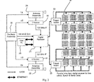
- the imaging system is in one embodiment a real-time imaging system having a controller 20 which is responsible for all decision-making.
- the controller 20 controls display of the images and a graphical user interface.
- a digital receiver 21 can control the panels through trigger boards 22 and 23. Received radiation responses are via horn antenna circuits 24 and 25.
- the PC 20 connects to the digital receiver 21 using two Ethernet links. All PC instructions can be sent via the digital receiver 21 and all responses from the system are returned to the PC 20 via the digital receiver 21.
- the daisy-chain interconnection from the digital receiver 21 to the tiles 26 allows communication of general instructions and data, such as write instructions, uploading reflector switch patterns and diagnostics. In general, the daisy-chain links can be used for bi-directional communication.
- Fig. 2 shows trigger boards 22 and 23 and parallel links between them and each tile. These parallel links provide scan block addresses and synchronisation signals. Power is also supplied to the tiles 26 via the trigger boards 22 and 23.
- the radiation frequency used in one embodiment is 24.12 GHz. It has been found that a frequency range of 1GHz to 80GHz is particularly effective in some embodiments, and that a sub-range of 1GHz to 40GHz is particularly effective. However, it is envisaged that different wavelengths may be employed in other embodiments, up to 300GHz.
- An active microwave imaging system illuminates a predefined scan volume, and measures both the amplitude and phase of the received signal from each volume element in the scan volume. The amplitude and phase contrast from element to element is used to generate an image of the scan volume.
- the amplitude and phase of the received signal are functions of the geometry of the imaging rays, the geometry of the object, and the dielectric properties of the object. Analysis of amplitude and phase data allows computation of these object properties.
- the dielectric permittivity can be deduced from incident, reflected, and transmitted electromagnetic waves.
- the reflection and transmission of electromagnetic waves or rays are functions of the geometry, the surface texture and the wave impedance on both sides of the object interface.
- the wave impedance is dependent on the permeability and permittivity of the material. For most materials of concern permeability is not a differentiator and therefore can be ignored.
- the dielectric properties are related to the intrinsic material properties and state of the object.
- the permittivity can be used to classify the material.
- the scan geometry is based on a confocal system where a horn illuminates a reflect array and the reflect array is configured to focus the radiation at an element in the scan volume. The reflections are in turn refocused by a reflect array at the horn aperture.
- the reflect array is electronically configured to scan the focal point throughout the scan volume in a systematic way. Knowledge of the horn pattern and the scan strategy allows the system to compute the geometry associated with each volume element. This is often referred to as "ray tracing". Amplitude and phase variations between the object and the surrounding volume and the computed geometry are used to estimate the relative permittivity and thus facilitate categorization of the object using a database of material relative permittivities.
- Figs. 3 and 4 illustrate the geometry used in the estimation process.
- Fig. 3 is a case where the body is imaged and
- Fig. 4 is a case where a concealed object located on the body is detected and the relative permittivity of the object is estimated. All rays originating at the horn and terminating at the horn are used in the estimation process.
- the estimate of relative permittivity is based on the change in attenuation and phase delay between the situations in Figs.3 and 4 .
- the attenuation and phase delay are extracted from image data. These are then written in terms of the unknowns - relative permittivity, and object thickness. The resulting equations are solved to arrive at an estimate of relative permittivity and object thickness.
- each incident ray generates an associated Ray 1 and Ray 2.
- the estimation process implemented by the imaging system accounts for all incident rays originating at the horn.
- Object detection software processes the image to identify objects on the body and the material classification software automatically reports an estimate of relative permittivity and its classification.
- the detection software uses edges in the images to identify anomalies.
- the material categorisation process can also be user-driven, an operator selecting a concealed object in the image and then selecting a nearby part of the body to use as a reference for the measurement.
- a ray Ep, with amplitude unity is emitted from the horn towards the patch p.
- the ray after reflection from the object is directed to patch q whose position is known using geometrical optics.
- the ray reflected from patch q is directed towards the horn.
- ⁇ q is the reflection coefficient related to reflection from the body and ⁇ q is the total electrical path length.
- the ray after being reflected by both the object and the body generates two rays, one is directed towards patch q1 and the other towards patch q2.
- the positions of patches q1 and q2 are known using geometrical optics.
- Gp, Gq1 and Gq2 are the horn gains at the patches p, q1 and q2.
- ⁇ q1 and ⁇ q2 are the reflection coefficients related to the object and body respectively.
- ⁇ q1 and ⁇ q2 are the respective electrical path lengths.
- the relative permittivity ⁇ r , and object thickness T are chosen to ensure a best fit of computed ⁇ model and ⁇ model to measured ⁇ and ⁇ .
- the calculation depicts the changing wave impedance and reflection coefficient when a wave flows from the horn to the target and back to the horn. It also uses the electromagnetic properties of wave impedance and reflection coefficient in the vicinity of boundaries.
- the transmitted beam is first computed, this then illuminates the body and threat resulting in a reflected beam.
- the reflected beam is in turn reflected from the panel to the horn.
- the signal received by the horn is used to compute the attenuation and phase shift between the transmitted and reflected signals, respectively ⁇ model and ⁇ model .
- the body can be modeled using a number of plates whose orientations are derived from the imaging data.
- the computation proceeds as normal except the computation of ⁇ model and ⁇ model takes account of the plates and their orientations.
- the body has a very high reflection index and therefore reflective plates are effective models.
- a 1m x 1m reflect array panel consisting of 15000 patches generates a Gaussian shaped beam.
- the wax is located 70cm in front of the imaging panel.
- the imaging spot step increment is 0.4cm horizontally, 0.4cm vertically and 1.25cm ahead.
- test points should lead to the right solution but, it is advisable to use multiple test points to find/confirm the appropriate dielectric permittivity and thickness.
- the invention provides the major advantage of utilising existing imaging system hardware to generate not only an image of the scan volume, but also an estimate of the permittivity of concealed objects.
- the system can suggest material identity based on the permittivity estimates.
Landscapes
- Engineering & Computer Science (AREA)
- Radar, Positioning & Navigation (AREA)
- Remote Sensing (AREA)
- Physics & Mathematics (AREA)
- General Physics & Mathematics (AREA)
- Computer Networks & Wireless Communication (AREA)
- Life Sciences & Earth Sciences (AREA)
- General Life Sciences & Earth Sciences (AREA)
- Geophysics (AREA)
- Electromagnetism (AREA)
- Radar Systems Or Details Thereof (AREA)
- Investigating Or Analysing Materials By Optical Means (AREA)
- Geophysics And Detection Of Objects (AREA)
- Aerials With Secondary Devices (AREA)
- Measurement Of Resistance Or Impedance (AREA)
Description
- The invention relates to imaging systems for identification of concealed items, for example imaging systems for security scanning. It applies to imaging systems which operate over any of a wide range of frequencies.
- In response to security threats in transportation and public spaces, inspection of people for materials such as narcotics and explosives and other types of contraband is becoming common at security checkpoints at, for example, airports, train stations, sporting events, concerts, federal buildings, and other public and private facilities. Systems using non-ionizing radiation, such as terahertz and millimetre range radiation, for imaging of concealed items of interest are known. Such systems are described in, for example,
WO200875948 US7304306 , andUS7295019 . -
WO200875948 -
US7304306 describes an imaging system using terahertz radiation, and a direct conversion detector module is used. Detected radiation is split into several components, which are attenuated. The objective is to detect explosive material. The different signals are combined to provide a composite signal. -
US7295019 describes use of capacitive and inductance sensors for detecting concealed items such as plastic explosives and ceramic knives. -
US2003/163042 (Salmon ) describes object detection using a radiation source. -
WO2006/067773 (Farran ) describes detection using a filter for partitioning bands. -
US2007/102629 (Richard et al ) describes use of polarized microwave signals. -
US6777684 (Rose Research) describes millimeter and sub-millimeter wave imaging. -
US7298318 (Agilent) describes imaging using a programmable transmission array. -
GB2424531 - The invention is directed towards providing for improved detection of non-metallic concealed items, particularly with improved differentiation between threat and non-threat items.
- An imaging system is as set out in claim 1.
- In one embodiment, said frequency is in the range of 1 GHz to 300GHz.
- In one embodiment, said frequency is in the range of 1 GHz to 80GHz.
- In one embodiment, the processor is adapted to classify materials based on a database of relative permittivities, and said database includes permittivity data or relative permittivity data for specified threat materials such as explosives or narcotics.
- In one embodiment, the system is adapted to detect radiation from two or more volume elements, a volume element providing reference data if it does not include the concealed material.
- In another embodiment, the processor is adapted to process amplitude and phase contrast from element to element in the scan volume to generate an image of the scan volume.
- In one embodiment, different amplitude and phase responses for the elements are used by the processor to detect the location and the orientation of a concealed material.
- In one embodiment, the transmitter and the receiver comprise a horn in a confocal arrangement, in which the horn illuminates the reflect array and the reflect array is configured to focus the radiation at an element in the scan volume, and the reflections are in turn refocused by the reflect array at the horn aperture, and the processor is adapted to control the reflect array to scan the focal point throughout the scan volume in a systematic way, and to use horn pattern and the scan strategy to compute the geometry associated with each volume clement in terms of individual rays, and in which amplitude and phase variations between the object and the surrounding volume and the computed geometry are used to estimate the relative permittivity.
- In one embodiment, for each transmitted ray data for two returned rays is processed by the processor, in which a first ray is reflected off the surface of the object and a second ray is transmitted through the object and reflected at an interface between the object and the body, and in which the processor is adapted to perform an estimation process which tracks both rays and identifies the following events:
- neither ray is recovered by the horn and therefore plays no part in the estimation process,
- the first ray is recovered and is accounted for in the estimation process but the second ray is lost,
- the second ray is recovered and is accounted for in the estimation process but the first ray is lost, and
- both rays are recovered and both contribute to the estimation process.
- In one embodiment, the processor is adapted to execute algorithms implementing Snell's law coupled to the electromagnetic properties of fields in the vicinity of boundaries to compute amplitude as a level of attenuation, and phase, τ model and Φmodel, of received radiation.
- In one embodiment, the processor is adapted to execute algorithms reflecting the electromagnetic properties of wave impedance and reflection coefficient in the vicinity of boundaries to compute amplitude as a level of attenuation, and phase, τ model and Φmodel, of received radiation.
- In one embodiment, the processor is adapted to execute confocal image theory algorithms to compute amplitude as a level of attenuation and phase, τ model and Φmodel, of received radiation.
- In one embodiment, the system further comprises a reflector for reflecting scattered radiation, and the receiver is mounted to receive radiation after being reflected.
- In one embodiment, the reflect array is configured to focus the transmitted radiation at successive elements in the scan volume.
- In one embodiment, the transmitter and the receiver comprise a horn antenna, and the system comprises a reflect array arranged in tiles, each tile consisting of an array of patch antennas with switching transistors and an associated controller for controlling the transistors, and in which the controller is adapted to configure phases of the patch antennas to achieve a particular pattern in space when the array is illuminated by the horn antenna, in which the processor is adapted to:
- calculate and sum distance from the horn antenna to a patch and distance from the patch to the focal point,
- convert said distance into wavelengths at the operating frequency, and
- convert a fractional portion of the distance into phase by multiplying by a number of degrees, and in which for each patch to constructively contribute to the focus the phases must be substantially identical.
- In one embodiment, a transistor is selected to add 0 or 180 degree phase shift depending on the calculated phase by turning it on and 0 degrees by turning it off, scanning being implemented over the volume by applying appropriate patterns of switching the transistors.
- The invention will be more clearly understood from the following description of some embodiments thereof, given by way of example only with reference to the accompanying drawings in which:-
-
Figs. 1 and2 are diagrams illustrating hardware of a system of the invention; -
Fig. 3 is a diagram illustrating incident and scattered radiation where there is no potential threat object present; and -
Fig. 4 shows the radiation where there is a potential threat. - The invention involves using different views taken using active microwave imaging hardware, and automatically classifying a material carried on the human body as safe or as a potential threat material. The automatic classification is based on the fact that the human body has a much higher reflectivity (as its permittivity is much higher) than many dielectric materials such as explosives or narcotic potential threat materials.
- In this specification, unless explicitly stated otherwise, "and" can mean "or," and "or" can mean "and." For example, if a feature is described as having A, B, or C, the feature can have A, B, and C, or any combination of A, B, and C. Similarly, if a feature is described as having A, B, and C, the feature can have only one or two of A, B, or C.
- Unless explicitly stated otherwise, "a" and "an" can mean "one or more than one." For example, if a device is described as having a feature X, the device may have one or more of feature X.
- A microwave imaging system enables the detection of concealed threats on the human body, due to penetration of microwaves through materials. The term microwave in this context refers to electromagnetic radiation in the frequency range of 1 to 300GHz.
- An imaging system can use any non-ionizing radiation, including but not limited to millimetre wave or terahertz radiation. In one embodiment the system uses millimetre wave illumination to image an object. The incident beam can be focused using the reflect array. For imaging, the reflect array can be arranged in tiles. Each tile can consist of an array of patch antennas with switching FETs and the associated electronics for controlling the FETs. Each panel constitutes a reflect array. The phases of the individual patches can be configured to achieve a particular pattern in space when the array is illuminated by a horn antenna. The distance from the horn to a patch and the distance from the patch to the focal point can be calculated and summed. The resulting distance can then be converted into wavelengths at the operating frequency. The fractional portion of the distance can be converted into phase by multiplying by 360 degrees. For each patch to constructively contribute to the focus, the phases resulting from the above calculation should be identical or substantially identical. It is possible to approximate this by having the phases agree by better than 180 degrees. To achieve this, the FETs can be selected to add 0 or 180 degree phase shift depending on the calculated phase. A FET can be configured to deliver a phase shift of 180 degrees by turning it on and 0 degrees by turning it off. Thus, scanning can be implemented over a volume by applying appropriate patterns of ones and zeroes to the FETs.
- Referring to
Figs. 1 and2 , the imaging system is in one embodiment a real-time imaging system having acontroller 20 which is responsible for all decision-making. Thecontroller 20 controls display of the images and a graphical user interface. Adigital receiver 21 can control the panels throughtrigger boards horn antenna circuits PC 20 connects to thedigital receiver 21 using two Ethernet links. All PC instructions can be sent via thedigital receiver 21 and all responses from the system are returned to thePC 20 via thedigital receiver 21. The daisy-chain interconnection from thedigital receiver 21 to thetiles 26 allows communication of general instructions and data, such as write instructions, uploading reflector switch patterns and diagnostics. In general, the daisy-chain links can be used for bi-directional communication.Fig. 2 shows triggerboards tiles 26 via thetrigger boards - The radiation frequency used in one embodiment is 24.12 GHz. It has been found that a frequency range of 1GHz to 80GHz is particularly effective in some embodiments, and that a sub-range of 1GHz to 40GHz is particularly effective. However, it is envisaged that different wavelengths may be employed in other embodiments, up to 300GHz.
- In order for a threat to be detectable with microwaves, it needs to have properties that, in terms of electromagnetic wave propagation, are different compared to the surrounding material (human body).
- An active microwave imaging system illuminates a predefined scan volume, and measures both the amplitude and phase of the received signal from each volume element in the scan volume. The amplitude and phase contrast from element to element is used to generate an image of the scan volume.
- The amplitude and phase of the received signal are functions of the geometry of the imaging rays, the geometry of the object, and the dielectric properties of the object. Analysis of amplitude and phase data allows computation of these object properties.
- Electrical properties of the objects, such as the dielectric permittivity, can be deduced from incident, reflected, and transmitted electromagnetic waves. The reflection and transmission of electromagnetic waves or rays are functions of the geometry, the surface texture and the wave impedance on both sides of the object interface. The wave impedance is dependent on the permeability and permittivity of the material. For most materials of concern permeability is not a differentiator and therefore can be ignored. The dielectric properties are related to the intrinsic material properties and state of the object. The dielectric permittivity ∈ is complex (∈ = ∈' - j ∈"), ∈' and ∈" are respectively related to energy storage and energy dissipation in the material. The permittivity can be used to classify the material.
- The scan geometry is based on a confocal system where a horn illuminates a reflect array and the reflect array is configured to focus the radiation at an element in the scan volume. The reflections are in turn refocused by a reflect array at the horn aperture. The reflect array is electronically configured to scan the focal point throughout the scan volume in a systematic way. Knowledge of the horn pattern and the scan strategy allows the system to compute the geometry associated with each volume element. This is often referred to as "ray tracing". Amplitude and phase variations between the object and the surrounding volume and the computed geometry are used to estimate the relative permittivity and thus facilitate categorization of the object using a database of material relative permittivities.
-
Figs. 3 and 4 illustrate the geometry used in the estimation process.Fig. 3 is a case where the body is imaged andFig. 4 is a case where a concealed object located on the body is detected and the relative permittivity of the object is estimated. All rays originating at the horn and terminating at the horn are used in the estimation process. - The estimate of relative permittivity is based on the change in attenuation and phase delay between the situations in
Figs.3 and 4 . The attenuation and phase delay are extracted from image data. These are then written in terms of the unknowns - relative permittivity, and object thickness. The resulting equations are solved to arrive at an estimate of relative permittivity and object thickness. - For each transmitted ray two returned rays must be considered, as illustrated in
Fig. 4 . Ray 1 (detected as q1) is reflected off the surface of the object and ray 2 (detected as q2) is transmitted through the object and reflected at the interface between the object and the body. Internal reflection from the object surface is discounted. The imaging system performs an estimation process which tracks both rays and accounts for four eventualities: - 1) Neither ray is recovered by the horn and therefore plays no part in the estimation process.
- 2) Ray 1 is recovered and is accounted for in the estimation process but Ray 2 is lost.
- 3) Ray 2 is recovered and is accounted for in the estimation process but Ray 1 is lost.
- 4) Both rays are recovered and both contribute to the estimation process.
- As described above, each incident ray generates an associated Ray 1 and Ray 2. The estimation process implemented by the imaging system accounts for all incident rays originating at the horn.
- Object detection software processes the image to identify objects on the body and the material classification software automatically reports an estimate of relative permittivity and its classification. The detection software uses edges in the images to identify anomalies.
- The material categorisation process can also be user-driven, an operator selecting a concealed object in the image and then selecting a nearby part of the body to use as a reference for the measurement.
- A ray Ep, with amplitude unity is emitted from the horn towards the patch p.
In the case ofFig. 1 , the ray, after reflection from the object is directed to patch q whose position is known using geometrical optics. The ray reflected from patch q is directed towards the horn. The received ray with complex amplitude Rp is given by Rp=Ep.Gp.ρq.Gq.exp(iϕq) where Gp and Gq are the horn gains at the patches p and q. ρq is the reflection coefficient related to reflection from the body and φq is the total electrical path length. - In the case of
Fig. 4 , the ray, after being reflected by both the object and the body generates two rays, one is directed towards patch q1 and the other towards patch q2. The positions of patches q1 and q2 are known using geometrical optics. The reflected rays from patches q1 and q2 are directed towards the horn, therefore, the received composite ray with complex amplitude Rp is given by Rp=Ep.Gp.(ρq1.Gq1.exp(iϕq1) + ρq2.Gq2.exp(iϕq2)) where Gp, Gq1 and Gq2 are the horn gains at the patches p, q1 and q2. ρq1 and ρq2 are the reflection coefficients related to the object and body respectively. φq1 and φq2 are the respective electrical path lengths. - The signal received in
Fig. 4 is attenuated and phase shifted with respect to the signal received inFig. 3 .
- ρp is the attenuation relative to the ray emitted to patch p.
- ϕp is the phase shift relative to the ray emitted to patch p.
- All rays originating at the horn (a ray per patch) are used in the estimation of the attenuation (τ) and the phase shift (Φ) between the received signals in
Figs. 3 and 4 .

- The relative permittivity ∈r, and object thickness T are chosen to ensure a best fit of computed τ model and Φmodel to measured τ and Φ.
- There are several methods available to perform the calculation of τ model and Φmodel.
- Snell's law coupled to the electromagnetic properties of fields in the vicinity of boundaries are used to compute τ model and Φmodel.
- In order to compute τ model and Φmodel, the calculation depicts the changing wave impedance and reflection coefficient when a wave flows from the horn to the target and back to the horn. It also uses the electromagnetic properties of wave impedance and reflection coefficient in the vicinity of boundaries.
- The transmitted beam is first computed, this then illuminates the body and threat resulting in a reflected beam. The reflected beam is in turn reflected from the panel to the horn. The signal received by the horn is used to compute the attenuation and phase shift between the transmitted and reflected signals, respectively τ model and Φmodel.
- If the threat object is not located on a flat part of the body, the body can be modeled using a number of plates whose orientations are derived from the imaging data. The computation proceeds as normal except the computation of τ model and Φmodel takes account of the plates and their orientations.
- The body has a very high reflection index and therefore reflective plates are effective models.
- A 1m x 1m reflect array panel consisting of 15000 patches generates a Gaussian shaped beam. The beam is used to image a block of wax (∈=2.59) 1.8cm thick which is taped to a reflective surface (representing a human body). The wax is located 70cm in front of the imaging panel. The imaging spot step increment is 0.4cm horizontally, 0.4cm vertically and 1.25cm ahead.
- A simple processing of the results indicates the location of the wax and gives a close indication of its width and length. It also states that the wax thickness is between Tmin=1.2cm and Tmax=2.4cm.
- Two volume elements are chosen as test points, one is located inside the threat and the other is located on the body but outside the threat. Thickness and dielectric permittivity values are respectively being swept between Tmin and Tmax (step of 0.2cm), ∈min and ∈max (∈min=1 and ∈max=4 step =0.5). Method 3 was used to compute τ model and Φmodel for the chosen test points. Computation results are then compared to measurement results in order to find wax dielectric permittivity and thickness. The best match for the two test points was achieved with a thickness of 1.6cm and a dielectric permittivity of 2.5.
- Ideally, two test points should lead to the right solution but, it is advisable to use multiple test points to find/confirm the appropriate dielectric permittivity and thickness.
- The invention provides the major advantage of utilising existing imaging system hardware to generate not only an image of the scan volume, but also an estimate of the permittivity of concealed objects. When coupled with an appropriate data-base the system can suggest material identity based on the permittivity estimates.
- The invention is not limited to the embodiments described but may be varied in construction and detail, within the scope of the appended claims.
Claims (15)
- An imaging system comprising
a transmitter (24) for directing radiation at a scan volume in which there is a target;
a receiver (21, 24) for receiving scattered radiation from the volume; and
a processor (20, 21) for processing the scattered radiation to generate an image according to amplitude and phase of the received radiation;
a display (20) coupled to the processor, for generating an image display;
wherein the transmitter (24) is adapted to transmit the incident radiation with a substantially single frequency;
the system is adapted to identify a concealed material;
wherein the processor (20) is adapted to classify a concealed dielectric material according to permittivity relative to that of the human body, said relative permittivity being deduced from amplitude and phase information in the received radiation;
characterized in that the system comprises a reflect array (26) for focusing incident beam radiation and in that the processor (20) is adapted to measure phase and amplitude of scattered radiation both near the concealed material and at the concealed material, that near the concealed material providing a reference;
wherein the system is adapted to detect radiation from two or more volume elements, a volume element providing reference data if it does not include the concealed material, and
the processor (20) is adapted to automatically identify anomalies at edges in the recorded images, and to use said anomalies when deriving relative permittivity data. - An imaging system as claimed in claim 1, wherein said frequency is in the range of 1GHz to 300GHz.
- An imaging system as claimed in claim 2, wherein said frequency is in the range of 1GHz to 80GHz.
- An imaging system as claimed in any preceding claim, wherein the processor (20) is adapted to classify materials based on a database of relative permittivities, and said database includes permittivity data or relative permittivity data for specified threat materials such as explosives or narcotics.
- An imaging system as claimed in any preceding claim, wherein the processor is adapted to process amplitude and phase contrast from element to element in the scan volume to generate an image of the scan volume.
- An imaging system as claimed in claim 5, wherein different amplitude and phase responses for the elements are used by the processor to detect the location and the orientation of a concealed material.
- An imaging system as claimed in any preceding claim, wherein the transmitter and the receiver comprise a horn (24) in a confocal arrangement, in which the horn illuminates said reflect array (26) and the reflect array is configured to focus the radiation at an element in the scan volume, and the reflections are in turn refocused by the reflect array at the horn (24) aperture, and the processor (20, 21) is adapted to control the reflect array to scan the focal point throughout the scan volume in a systematic way, and to use horn pattern and the scan strategy to compute the geometry associated with each volume element in terms of individual rays, and in which amplitude and phase variations between the object and the surrounding volume and the computed geometry are used to estimate the relative permittivity.
- An imaging system as claimed in claim 7, wherein for each transmitted ray data for two returned rays is processed by the processor, in which a first ray is reflected off the surface of the object and a second ray is transmitted through the object and reflected at an interface between the object and the body, and in which the processor is adapted to perform an estimation process which tracks both rays and identifies the following events:neither ray is recovered by the horn and therefore plays no part in the estimation process,the first ray is recovered and is accounted for in the estimation process but the second ray is lost,the second ray is recovered and is accounted for in the estimation process but the first ray is lost, andboth rays are recovered and both contribute to the estimation process.
- An imaging system as claimed in any preceding claim, wherein the processor is adapted to execute algorithms implementing Snell's law coupled to the electromagnetic properties of fields in the vicinity of boundaries to compute amplitude as a level of attenuation, and phase, τmodel and Φmodel, of received radiation.
- An imaging system as claimed in any preceding claim, wherein the processor is adapted to execute algorithms reflecting the electromagnetic properties of wave impedance and reflection coefficient in the vicinity of boundaries to compute amplitude as a level of attenuation, and phase, τmodel and Φmodel, of received radiation.
- An imaging system as claimed in any preceding claim, wherein the processor is adapted to execute confocal image theory algorithms to compute amplitude as a level of attenuation and phase, τmodel and Φmodel, of received radiation.
- An imaging system as claimed in any preceding claim, further comprising a reflector for reflecting scattered radiation, and the receiver is mounted to receive radiation after being reflected.
- An imaging system as claimed in claim 12, wherein said reflect array (26) is configured to focus the transmitted radiation at successive elements in the scan volume.
- An imaging system as claimed in any preceding claim, wherein the transmitter and the receiver comprise a horn antenna (24), and wherein said reflect array (26) is arranged in tiles, each tile consisting of an array of patch antennas with switching transistors and an associated controller for controlling the transistors, and in which the controller is adapted to configure phases of the patch antennas to achieve a particular pattern in space when the array is illuminated by the horn antenna, in which the processor is adapted to:calculate and sum distance from the horn antenna to a patch and distance from the patch to the focal point,convert said distance into wavelengths at the operating frequency, andconvert a fractional portion of the distance into phase by multiplying by a number of degrees, and in which for each patch to constructively contribute to the focus the phases must be substantially identical.
- An imaging system as claimed in claim 14, wherein a transistor is selected to add 0 or 180 degree phase shift depending on the calculated phase by turning it on and 0 degrees by turning it off, scanning being implemented over the volume by applying appropriate patterns of switching the transistors.
Applications Claiming Priority (2)
| Application Number | Priority Date | Filing Date | Title |
|---|---|---|---|
| IE20080540 | 2008-07-01 | ||
| PCT/IE2009/000043 WO2010001377A2 (en) | 2008-07-01 | 2009-07-01 | Identification of potential threat materials using active electromagnetic waves |
Publications (2)
| Publication Number | Publication Date |
|---|---|
| EP2304476A2 EP2304476A2 (en) | 2011-04-06 |
| EP2304476B1 true EP2304476B1 (en) | 2019-01-09 |
Family
ID=41466390
Family Applications (1)
| Application Number | Title | Priority Date | Filing Date |
|---|---|---|---|
| EP09773035.2A Active EP2304476B1 (en) | 2008-07-01 | 2009-07-01 | Identification of potential threat materials using active electromagnetic waves |
Country Status (5)
| Country | Link |
|---|---|
| US (1) | US8390504B2 (en) |
| EP (1) | EP2304476B1 (en) |
| CN (1) | CN102105816B (en) |
| RU (1) | RU2515956C2 (en) |
| WO (1) | WO2010001377A2 (en) |
Families Citing this family (30)
| Publication number | Priority date | Publication date | Assignee | Title |
|---|---|---|---|---|
| US9123999B2 (en) | 2010-01-15 | 2015-09-01 | Smiths Detection Ireland Limited | Imaging system |
| US8573529B2 (en) * | 2010-03-01 | 2013-11-05 | Farrokh Mohamadi | Standoff detection of motion and concealed unexploded ordnance (UXO) |
| WO2011128882A1 (en) * | 2010-04-15 | 2011-10-20 | Smiths Detection Ireland Limited | An imaging system |
| US8890073B2 (en) * | 2011-03-28 | 2014-11-18 | Northrop Grumman Guidance And Electronics Company, Inc. | Systems and methods for detecting and/or identifying materials based on electromagnetic radiation |
| US8946641B2 (en) * | 2011-04-07 | 2015-02-03 | The United States Of America, As Represented By The Secretary, Department Of Homeland Security | Method for identifying materials using dielectric properties through active millimeter wave illumination |
| EP2697671A2 (en) * | 2011-04-15 | 2014-02-19 | Ariel-University Research and Development Company, Ltd | Passive millimeter-wave detector |
| DE102011078539A1 (en) * | 2011-06-08 | 2012-12-13 | Rohde & Schwarz Gmbh & Co. Kg | Method and device for expanding the illumination of a test object |
| US9268017B2 (en) * | 2011-07-29 | 2016-02-23 | International Business Machines Corporation | Near-field millimeter wave imaging |
| NL1039057C2 (en) * | 2011-09-16 | 2013-03-19 | Karel Pieter Gijsbert Gerla | METHOD AND DEVICE FOR A CONTACTLESS RECOGNITION SYSTEM OF A MATERIAL. |
| US20140028494A1 (en) * | 2012-07-26 | 2014-01-30 | The Aerospace Corporation | Virtual Aperture Radar |
| WO2014033896A1 (en) * | 2012-08-31 | 2014-03-06 | 株式会社日立製作所 | Electromagnetic wave visualization device |
| EP3114464A4 (en) * | 2014-03-07 | 2017-11-29 | Rapiscan Systems, Inc. | Ultra wide band detectors |
| US11280898B2 (en) | 2014-03-07 | 2022-03-22 | Rapiscan Systems, Inc. | Radar-based baggage and parcel inspection systems |
| JP6271384B2 (en) * | 2014-09-19 | 2018-01-31 | 株式会社東芝 | Inspection device |
| US10222467B2 (en) * | 2015-11-10 | 2019-03-05 | Northrop Grumman Systems Corporation | Two-way coded aperture three-dimensional radar imaging |
| US10416094B2 (en) * | 2016-03-31 | 2019-09-17 | Northeastern University | Characterization of dielectric slabs attached to the body using focused millimeter waves |
| CN106371148B (en) * | 2016-09-27 | 2019-05-03 | 华讯方舟科技有限公司 | A kind of human body foreign body detection method and system based on millimeter-wave image |
| EP3593189A1 (en) * | 2017-03-10 | 2020-01-15 | Heraeus Noblelight America LLC | Device including a radiation emitter for applying radiation to a target, and related methods |
| CN108931540A (en) * | 2017-05-27 | 2018-12-04 | 富士通株式会社 | Article detection apparatus |
| CN108956647A (en) * | 2017-05-27 | 2018-12-07 | 富士通株式会社 | Article detection method and device |
| CN108957565A (en) * | 2017-05-27 | 2018-12-07 | 富士通株式会社 | Article detection method and device |
| CN109765548B (en) * | 2017-11-10 | 2023-09-08 | 富士通株式会社 | Article detection method and device |
| CN109782368A (en) * | 2017-11-10 | 2019-05-21 | 富士通株式会社 | Article detection method and device |
| EP3769111A1 (en) * | 2018-03-23 | 2021-01-27 | Xonar Technology Inc. | System and method for detecting object patterns using ultra-wideband (uwb) radar |
| GB201807616D0 (en) * | 2018-05-10 | 2018-06-27 | Radio Physics Solutions Ltd | Improvements in or relating to threat classification |
| US10804942B2 (en) | 2018-05-24 | 2020-10-13 | Analog Devices, Inc. | State-machine based body scanner imaging system |
| RU2691982C1 (en) * | 2018-05-29 | 2019-06-19 | Общество с ограниченной ответственностью "Локаторная техника" | Design of multifunctional radar screening system |
| CN110554439B (en) * | 2018-06-04 | 2021-07-23 | 富士通株式会社 | Article detection method and apparatus |
| RU2723987C1 (en) * | 2019-07-23 | 2020-06-18 | Роман Евгеньевич Стахно | Method of detection and identification of explosive and narcotic substances and device for its implementation |
| CN111308467A (en) * | 2020-03-10 | 2020-06-19 | 宁波飞芯电子科技有限公司 | Detection method and detection device |
Citations (1)
| Publication number | Priority date | Publication date | Assignee | Title |
|---|---|---|---|---|
| GB2424531A (en) * | 2005-03-24 | 2006-09-27 | Agilent Technologies Inc | Microwave imaging system for inspecting transportable items |
Family Cites Families (31)
| Publication number | Priority date | Publication date | Assignee | Title |
|---|---|---|---|---|
| US5227800A (en) * | 1988-04-19 | 1993-07-13 | Millitech Corporation | Contraband detection system |
| GB8825435D0 (en) * | 1988-10-31 | 1988-12-29 | Cross T E | Detection of non metallic material |
| US5363050A (en) * | 1990-08-31 | 1994-11-08 | Guo Wendy W | Quantitative dielectric imaging system |
| US5365237A (en) * | 1993-05-13 | 1994-11-15 | Thermo Trex Corporation | Microwave camera |
| US5704355A (en) * | 1994-07-01 | 1998-01-06 | Bridges; Jack E. | Non-invasive system for breast cancer detection |
| US5592170A (en) * | 1995-04-11 | 1997-01-07 | Jaycor | Radar system and method for detecting and discriminating targets from a safe distance |
| GB9700966D0 (en) * | 1997-01-17 | 1997-03-05 | Secr Defence | Millimetre wave imaging apparatus |
| US6057761A (en) * | 1997-01-21 | 2000-05-02 | Spatial Dynamics, Ltd. | Security system and method |
| FI107407B (en) * | 1997-09-16 | 2001-07-31 | Metorex Internat Oy | A submillimeter wave imaging system |
| US6777684B1 (en) * | 1999-08-23 | 2004-08-17 | Rose Research L.L.C. | Systems and methods for millimeter and sub-millimeter wave imaging |
| WO2002017231A2 (en) * | 2000-08-23 | 2002-02-28 | Rose Research Llc | Systems and methods for millimeter and sub-millimeter wave imaging |
| US6480141B1 (en) * | 2001-03-13 | 2002-11-12 | Sandia Corporation | Detection of contraband using microwave radiation |
| US7365672B2 (en) * | 2001-03-16 | 2008-04-29 | Battelle Memorial Institute | Detection of a concealed object |
| US6501414B2 (en) * | 2001-04-02 | 2002-12-31 | The United States Of America As Represented By The United States National Aeronautics And Space Administration | Method for locating a concealed object |
| US7194236B2 (en) * | 2001-09-28 | 2007-03-20 | Trex Enterprises Corp. | Millimeter wave imaging system |
| US6937182B2 (en) * | 2001-09-28 | 2005-08-30 | Trex Enterprises Corp. | Millimeter wave imaging system |
| GB0204167D0 (en) * | 2002-02-22 | 2002-04-10 | Qinetiq Ltd | Object detection apparatus and method |
| KR100986866B1 (en) * | 2002-04-26 | 2010-10-11 | 도시바 모바일 디스플레이 가부시키가이샤 | Method of driving el display device |
| US6791487B1 (en) * | 2003-03-07 | 2004-09-14 | Honeywell International Inc. | Imaging methods and systems for concealed weapon detection |
| US6861972B2 (en) * | 2003-07-28 | 2005-03-01 | Ellistar Sensor Systems, Inc. | Object detection apparatus and method |
| FR2864307A1 (en) * | 2003-12-19 | 2005-06-24 | Thales Sa | Non metallic object detecting device for e.g. airport, has analyzing unit with one unit for detecting energetic and polarimetric characteristics of reflected signal, and another unit detecting presence of objects in human body |
| RU2283485C2 (en) * | 2004-09-09 | 2006-09-10 | Закрытое акционерное общество "Интеллектуальные сканирующие системы" | Method for detection and identification of explosives |
| US7298318B2 (en) * | 2004-11-24 | 2007-11-20 | Agilent Technologies, Inc. | System and method for microwave imaging using programmable transmission array |
| IES20050856A2 (en) * | 2004-12-22 | 2006-08-09 | Farran Technology Ltd | A detection system |
| GB2421651B (en) * | 2004-12-23 | 2007-10-31 | Sensors & Software Inc | Data aquisition for a ground penetrating radar system |
| US20070139249A1 (en) * | 2005-12-16 | 2007-06-21 | Izhak Baharav | Handheld microwave imaging device |
| US20070139248A1 (en) * | 2005-12-16 | 2007-06-21 | Izhak Baharav | System and method for standoff microwave imaging |
| EP1996078A4 (en) * | 2006-03-10 | 2009-09-09 | Ind Res Ltd | Imaging system |
| US20080079625A1 (en) * | 2006-10-03 | 2008-04-03 | William Weems | System and method for stereoscopic anomaly detection using microwave imaging |
| JP4963640B2 (en) * | 2006-10-10 | 2012-06-27 | キヤノン株式会社 | Object information acquisition apparatus and method |
| US7504993B2 (en) * | 2006-10-12 | 2009-03-17 | Agilent Technolgoies, Inc. | Coaxial bi-modal imaging system for combined microwave and optical imaging |
-
2009
- 2009-07-01 EP EP09773035.2A patent/EP2304476B1/en active Active
- 2009-07-01 RU RU2011102320/28A patent/RU2515956C2/en active
- 2009-07-01 CN CN200980129370.2A patent/CN102105816B/en active Active
- 2009-07-01 WO PCT/IE2009/000043 patent/WO2010001377A2/en active Application Filing
- 2009-07-01 US US13/000,876 patent/US8390504B2/en active Active
Patent Citations (1)
| Publication number | Priority date | Publication date | Assignee | Title |
|---|---|---|---|---|
| GB2424531A (en) * | 2005-03-24 | 2006-09-27 | Agilent Technologies Inc | Microwave imaging system for inspecting transportable items |
Also Published As
| Publication number | Publication date |
|---|---|
| WO2010001377A3 (en) | 2010-12-16 |
| CN102105816A (en) | 2011-06-22 |
| CN102105816B (en) | 2015-08-05 |
| RU2515956C2 (en) | 2014-05-20 |
| EP2304476A2 (en) | 2011-04-06 |
| WO2010001377A2 (en) | 2010-01-07 |
| US20110102235A1 (en) | 2011-05-05 |
| US8390504B2 (en) | 2013-03-05 |
| RU2011102320A (en) | 2012-08-10 |
Similar Documents
| Publication | Publication Date | Title |
|---|---|---|
| EP2304476B1 (en) | Identification of potential threat materials using active electromagnetic waves | |
| US10466351B2 (en) | Remote detection and measurement of objects | |
| US9335407B2 (en) | Detection of objects | |
| Dehmollaian et al. | Refocusing through building walls using synthetic aperture radar | |
| US20100005044A1 (en) | Remote Detection and Measurement of Objects | |
| JP2006267102A (en) | System and method for inspecting transportable items using microwave imaging | |
| Liao et al. | Large-scale, full-wave-based emulation of step-frequency forward-looking radar imaging in rough terrain environments | |
| Yektakhah et al. | All-directions through-the-wall imaging using a small number of moving omnidirectional bi-static FMCW transceivers | |
| GB2487132A (en) | Examining an object using electromagnetic millimeter waves | |
| Soldovieri et al. | Sparse tomographic inverse scattering approach for through-the-wall radar imaging | |
| Elboushi et al. | MMW sensor for hidden targets detection and warning based on reflection/scattering approach | |
| Pisa et al. | Comparison between delay and sum and range migration algorithms for image reconstruction in through-the-wall radar imaging systems | |
| Zhang et al. | Single-frequency imaging and material characterization using reconfigurable reflectarrays | |
| Wang | UWB pulse radar for human imaging and doppler detection applications | |
| Sizov et al. | Forward scatter RCS estimation for ground targets | |
| García-Fernández et al. | Single Channel Frequency Diverse Computational Imaging System for Through-the-Wall Sensing | |
| RU2522853C1 (en) | Method and apparatus for detecting and identifying objects hidden under clothes on human body | |
| Sadeghi et al. | Modeling the response of dielectric slabs on ground planes using CW focused millimeter waves | |
| McMakin et al. | Millimeter-wave imaging for concealed weapon detection | |
| Zhang et al. | Single-frequency material characterization using a microwave adaptive reflect-array | |
| Gomez-Sousa et al. | Modeling and imaging security threats using a single-frequency adaptable reflect-array | |
| Essen et al. | 3D millimetre-wave scanner for luggage and parcels | |
| Zhang et al. | Wall parameters measurement and compensation cross-locating detection method for through wall radar | |
| Ravan et al. | Microwave holography for near-field imaging | |
| Van den Bulcke et al. | Plane wave and Gaussian beam scattering by long dielectric cylinders: 2.5 D simulations versus measurements |
Legal Events
| Date | Code | Title | Description |
|---|---|---|---|
| PUAI | Public reference made under article 153(3) epc to a published international application that has entered the european phase |
Free format text: ORIGINAL CODE: 0009012 |
|
| 17P | Request for examination filed |
Effective date: 20110118 |
|
| AK | Designated contracting states |
Kind code of ref document: A2 Designated state(s): AT BE BG CH CY CZ DE DK EE ES FI FR GB GR HR HU IE IS IT LI LT LU LV MC MK MT NL NO PL PT RO SE SI SK TR |
|
| AX | Request for extension of the european patent |
Extension state: AL BA RS |
|
| DAX | Request for extension of the european patent (deleted) | ||
| STAA | Information on the status of an ep patent application or granted ep patent |
Free format text: STATUS: EXAMINATION IS IN PROGRESS |
|
| 17Q | First examination report despatched |
Effective date: 20170904 |
|
| GRAP | Despatch of communication of intention to grant a patent |
Free format text: ORIGINAL CODE: EPIDOSNIGR1 |
|
| STAA | Information on the status of an ep patent application or granted ep patent |
Free format text: STATUS: GRANT OF PATENT IS INTENDED |
|
| INTG | Intention to grant announced |
Effective date: 20181016 |
|
| GRAS | Grant fee paid |
Free format text: ORIGINAL CODE: EPIDOSNIGR3 |
|
| GRAA | (expected) grant |
Free format text: ORIGINAL CODE: 0009210 |
|
| STAA | Information on the status of an ep patent application or granted ep patent |
Free format text: STATUS: THE PATENT HAS BEEN GRANTED |
|
| AK | Designated contracting states |
Kind code of ref document: B1 Designated state(s): AT BE BG CH CY CZ DE DK EE ES FI FR GB GR HR HU IE IS IT LI LT LU LV MC MK MT NL NO PL PT RO SE SI SK TR |
|
| REG | Reference to a national code |
Ref country code: GB Ref legal event code: FG4D |
|
| REG | Reference to a national code |
Ref country code: CH Ref legal event code: EP Ref country code: AT Ref legal event code: REF Ref document number: 1088008 Country of ref document: AT Kind code of ref document: T Effective date: 20190115 |
|
| REG | Reference to a national code |
Ref country code: DE Ref legal event code: R096 Ref document number: 602009056648 Country of ref document: DE |
|
| REG | Reference to a national code |
Ref country code: IE Ref legal event code: FG4D |
|
| REG | Reference to a national code |
Ref country code: NL Ref legal event code: MP Effective date: 20190109 |
|
| REG | Reference to a national code |
Ref country code: LT Ref legal event code: MG4D |
|
| PG25 | Lapsed in a contracting state [announced via postgrant information from national office to epo] |
Ref country code: NL Free format text: LAPSE BECAUSE OF FAILURE TO SUBMIT A TRANSLATION OF THE DESCRIPTION OR TO PAY THE FEE WITHIN THE PRESCRIBED TIME-LIMIT Effective date: 20190109 |
|
| REG | Reference to a national code |
Ref country code: AT Ref legal event code: MK05 Ref document number: 1088008 Country of ref document: AT Kind code of ref document: T Effective date: 20190109 |
|
| PG25 | Lapsed in a contracting state [announced via postgrant information from national office to epo] |
Ref country code: FI Free format text: LAPSE BECAUSE OF FAILURE TO SUBMIT A TRANSLATION OF THE DESCRIPTION OR TO PAY THE FEE WITHIN THE PRESCRIBED TIME-LIMIT Effective date: 20190109 Ref country code: LT Free format text: LAPSE BECAUSE OF FAILURE TO SUBMIT A TRANSLATION OF THE DESCRIPTION OR TO PAY THE FEE WITHIN THE PRESCRIBED TIME-LIMIT Effective date: 20190109 Ref country code: ES Free format text: LAPSE BECAUSE OF FAILURE TO SUBMIT A TRANSLATION OF THE DESCRIPTION OR TO PAY THE FEE WITHIN THE PRESCRIBED TIME-LIMIT Effective date: 20190109 Ref country code: PL Free format text: LAPSE BECAUSE OF FAILURE TO SUBMIT A TRANSLATION OF THE DESCRIPTION OR TO PAY THE FEE WITHIN THE PRESCRIBED TIME-LIMIT Effective date: 20190109 Ref country code: PT Free format text: LAPSE BECAUSE OF FAILURE TO SUBMIT A TRANSLATION OF THE DESCRIPTION OR TO PAY THE FEE WITHIN THE PRESCRIBED TIME-LIMIT Effective date: 20190509 Ref country code: SE Free format text: LAPSE BECAUSE OF FAILURE TO SUBMIT A TRANSLATION OF THE DESCRIPTION OR TO PAY THE FEE WITHIN THE PRESCRIBED TIME-LIMIT Effective date: 20190109 Ref country code: NO Free format text: LAPSE BECAUSE OF FAILURE TO SUBMIT A TRANSLATION OF THE DESCRIPTION OR TO PAY THE FEE WITHIN THE PRESCRIBED TIME-LIMIT Effective date: 20190409 |
|
| PG25 | Lapsed in a contracting state [announced via postgrant information from national office to epo] |
Ref country code: LV Free format text: LAPSE BECAUSE OF FAILURE TO SUBMIT A TRANSLATION OF THE DESCRIPTION OR TO PAY THE FEE WITHIN THE PRESCRIBED TIME-LIMIT Effective date: 20190109 Ref country code: HR Free format text: LAPSE BECAUSE OF FAILURE TO SUBMIT A TRANSLATION OF THE DESCRIPTION OR TO PAY THE FEE WITHIN THE PRESCRIBED TIME-LIMIT Effective date: 20190109 Ref country code: IS Free format text: LAPSE BECAUSE OF FAILURE TO SUBMIT A TRANSLATION OF THE DESCRIPTION OR TO PAY THE FEE WITHIN THE PRESCRIBED TIME-LIMIT Effective date: 20190509 Ref country code: BG Free format text: LAPSE BECAUSE OF FAILURE TO SUBMIT A TRANSLATION OF THE DESCRIPTION OR TO PAY THE FEE WITHIN THE PRESCRIBED TIME-LIMIT Effective date: 20190409 Ref country code: GR Free format text: LAPSE BECAUSE OF FAILURE TO SUBMIT A TRANSLATION OF THE DESCRIPTION OR TO PAY THE FEE WITHIN THE PRESCRIBED TIME-LIMIT Effective date: 20190410 |
|
| REG | Reference to a national code |
Ref country code: DE Ref legal event code: R097 Ref document number: 602009056648 Country of ref document: DE |
|
| PG25 | Lapsed in a contracting state [announced via postgrant information from national office to epo] |
Ref country code: AT Free format text: LAPSE BECAUSE OF FAILURE TO SUBMIT A TRANSLATION OF THE DESCRIPTION OR TO PAY THE FEE WITHIN THE PRESCRIBED TIME-LIMIT Effective date: 20190109 Ref country code: EE Free format text: LAPSE BECAUSE OF FAILURE TO SUBMIT A TRANSLATION OF THE DESCRIPTION OR TO PAY THE FEE WITHIN THE PRESCRIBED TIME-LIMIT Effective date: 20190109 Ref country code: CZ Free format text: LAPSE BECAUSE OF FAILURE TO SUBMIT A TRANSLATION OF THE DESCRIPTION OR TO PAY THE FEE WITHIN THE PRESCRIBED TIME-LIMIT Effective date: 20190109 Ref country code: RO Free format text: LAPSE BECAUSE OF FAILURE TO SUBMIT A TRANSLATION OF THE DESCRIPTION OR TO PAY THE FEE WITHIN THE PRESCRIBED TIME-LIMIT Effective date: 20190109 Ref country code: SK Free format text: LAPSE BECAUSE OF FAILURE TO SUBMIT A TRANSLATION OF THE DESCRIPTION OR TO PAY THE FEE WITHIN THE PRESCRIBED TIME-LIMIT Effective date: 20190109 Ref country code: IT Free format text: LAPSE BECAUSE OF FAILURE TO SUBMIT A TRANSLATION OF THE DESCRIPTION OR TO PAY THE FEE WITHIN THE PRESCRIBED TIME-LIMIT Effective date: 20190109 Ref country code: DK Free format text: LAPSE BECAUSE OF FAILURE TO SUBMIT A TRANSLATION OF THE DESCRIPTION OR TO PAY THE FEE WITHIN THE PRESCRIBED TIME-LIMIT Effective date: 20190109 |
|
| PLBE | No opposition filed within time limit |
Free format text: ORIGINAL CODE: 0009261 |
|
| STAA | Information on the status of an ep patent application or granted ep patent |
Free format text: STATUS: NO OPPOSITION FILED WITHIN TIME LIMIT |
|
| 26N | No opposition filed |
Effective date: 20191010 |
|
| PG25 | Lapsed in a contracting state [announced via postgrant information from national office to epo] |
Ref country code: SI Free format text: LAPSE BECAUSE OF FAILURE TO SUBMIT A TRANSLATION OF THE DESCRIPTION OR TO PAY THE FEE WITHIN THE PRESCRIBED TIME-LIMIT Effective date: 20190109 Ref country code: MC Free format text: LAPSE BECAUSE OF FAILURE TO SUBMIT A TRANSLATION OF THE DESCRIPTION OR TO PAY THE FEE WITHIN THE PRESCRIBED TIME-LIMIT Effective date: 20190109 |
|
| REG | Reference to a national code |
Ref country code: CH Ref legal event code: PL |
|
| PG25 | Lapsed in a contracting state [announced via postgrant information from national office to epo] |
Ref country code: TR Free format text: LAPSE BECAUSE OF FAILURE TO SUBMIT A TRANSLATION OF THE DESCRIPTION OR TO PAY THE FEE WITHIN THE PRESCRIBED TIME-LIMIT Effective date: 20190109 |
|
| REG | Reference to a national code |
Ref country code: BE Ref legal event code: MM Effective date: 20190731 |
|
| PG25 | Lapsed in a contracting state [announced via postgrant information from national office to epo] |
Ref country code: LI Free format text: LAPSE BECAUSE OF NON-PAYMENT OF DUE FEES Effective date: 20190731 Ref country code: BE Free format text: LAPSE BECAUSE OF NON-PAYMENT OF DUE FEES Effective date: 20190731 Ref country code: LU Free format text: LAPSE BECAUSE OF NON-PAYMENT OF DUE FEES Effective date: 20190701 Ref country code: CH Free format text: LAPSE BECAUSE OF NON-PAYMENT OF DUE FEES Effective date: 20190731 |
|
| PG25 | Lapsed in a contracting state [announced via postgrant information from national office to epo] |
Ref country code: IE Free format text: LAPSE BECAUSE OF NON-PAYMENT OF DUE FEES Effective date: 20190701 |
|
| PG25 | Lapsed in a contracting state [announced via postgrant information from national office to epo] |
Ref country code: CY Free format text: LAPSE BECAUSE OF FAILURE TO SUBMIT A TRANSLATION OF THE DESCRIPTION OR TO PAY THE FEE WITHIN THE PRESCRIBED TIME-LIMIT Effective date: 20190109 |
|
| PG25 | Lapsed in a contracting state [announced via postgrant information from national office to epo] |
Ref country code: HU Free format text: LAPSE BECAUSE OF FAILURE TO SUBMIT A TRANSLATION OF THE DESCRIPTION OR TO PAY THE FEE WITHIN THE PRESCRIBED TIME-LIMIT; INVALID AB INITIO Effective date: 20090701 Ref country code: MT Free format text: LAPSE BECAUSE OF FAILURE TO SUBMIT A TRANSLATION OF THE DESCRIPTION OR TO PAY THE FEE WITHIN THE PRESCRIBED TIME-LIMIT Effective date: 20190109 |
|
| PG25 | Lapsed in a contracting state [announced via postgrant information from national office to epo] |
Ref country code: MK Free format text: LAPSE BECAUSE OF FAILURE TO SUBMIT A TRANSLATION OF THE DESCRIPTION OR TO PAY THE FEE WITHIN THE PRESCRIBED TIME-LIMIT Effective date: 20190109 |
|
| P01 | Opt-out of the competence of the unified patent court (upc) registered |
Effective date: 20230528 |
|
| PGFP | Annual fee paid to national office [announced via postgrant information from national office to epo] |
Ref country code: DE Payment date: 20230531 Year of fee payment: 15 |
|
| PGFP | Annual fee paid to national office [announced via postgrant information from national office to epo] |
Ref country code: GB Payment date: 20240530 Year of fee payment: 16 |
|
| PGFP | Annual fee paid to national office [announced via postgrant information from national office to epo] |
Ref country code: FR Payment date: 20240611 Year of fee payment: 16 |