EP2304429B1 - Verfahren zur überwachung und optimierung der additivkonzentration in brennstoff-ethanol - Google Patents
Verfahren zur überwachung und optimierung der additivkonzentration in brennstoff-ethanol Download PDFInfo
- Publication number
- EP2304429B1 EP2304429B1 EP09767833.8A EP09767833A EP2304429B1 EP 2304429 B1 EP2304429 B1 EP 2304429B1 EP 09767833 A EP09767833 A EP 09767833A EP 2304429 B1 EP2304429 B1 EP 2304429B1
- Authority
- EP
- European Patent Office
- Prior art keywords
- fuel ethanol
- corrosion inhibitor
- additive composition
- denaturant
- ethanol
- Prior art date
- Legal status (The legal status is an assumption and is not a legal conclusion. Google has not performed a legal analysis and makes no representation as to the accuracy of the status listed.)
- Active
Links
Images

Classifications
-
- G—PHYSICS
- G01—MEASURING; TESTING
- G01N—INVESTIGATING OR ANALYSING MATERIALS BY DETERMINING THEIR CHEMICAL OR PHYSICAL PROPERTIES
- G01N21/00—Investigating or analysing materials by the use of optical means, i.e. using sub-millimetre waves, infrared, visible or ultraviolet light
- G01N21/84—Systems specially adapted for particular applications
-
- G—PHYSICS
- G01—MEASURING; TESTING
- G01N—INVESTIGATING OR ANALYSING MATERIALS BY DETERMINING THEIR CHEMICAL OR PHYSICAL PROPERTIES
- G01N21/00—Investigating or analysing materials by the use of optical means, i.e. using sub-millimetre waves, infrared, visible or ultraviolet light
- G01N21/62—Systems in which the material investigated is excited whereby it emits light or causes a change in wavelength of the incident light
- G01N21/63—Systems in which the material investigated is excited whereby it emits light or causes a change in wavelength of the incident light optically excited
- G01N21/64—Fluorescence; Phosphorescence
- G01N21/6428—Measuring fluorescence of fluorescent products of reactions or of fluorochrome labelled reactive substances, e.g. measuring quenching effects, using measuring "optrodes"
- G01N21/643—Measuring fluorescence of fluorescent products of reactions or of fluorochrome labelled reactive substances, e.g. measuring quenching effects, using measuring "optrodes" non-biological material
-
- G—PHYSICS
- G01—MEASURING; TESTING
- G01N—INVESTIGATING OR ANALYSING MATERIALS BY DETERMINING THEIR CHEMICAL OR PHYSICAL PROPERTIES
- G01N21/00—Investigating or analysing materials by the use of optical means, i.e. using sub-millimetre waves, infrared, visible or ultraviolet light
- G01N21/62—Systems in which the material investigated is excited whereby it emits light or causes a change in wavelength of the incident light
- G01N21/63—Systems in which the material investigated is excited whereby it emits light or causes a change in wavelength of the incident light optically excited
- G01N21/64—Fluorescence; Phosphorescence
-
- G—PHYSICS
- G01—MEASURING; TESTING
- G01N—INVESTIGATING OR ANALYSING MATERIALS BY DETERMINING THEIR CHEMICAL OR PHYSICAL PROPERTIES
- G01N33/00—Investigating or analysing materials by specific methods not covered by groups G01N1/00 - G01N31/00
- G01N33/26—Oils; Viscous liquids; Paints; Inks
- G01N33/28—Oils, i.e. hydrocarbon liquids
- G01N33/2835—Specific substances contained in the oils or fuels
- G01N33/2852—Alcohol in fuels
-
- G—PHYSICS
- G01—MEASURING; TESTING
- G01N—INVESTIGATING OR ANALYSING MATERIALS BY DETERMINING THEIR CHEMICAL OR PHYSICAL PROPERTIES
- G01N2201/00—Features of devices classified in G01N21/00
- G01N2201/06—Illumination; Optics
- G01N2201/061—Sources
-
- G—PHYSICS
- G01—MEASURING; TESTING
- G01N—INVESTIGATING OR ANALYSING MATERIALS BY DETERMINING THEIR CHEMICAL OR PHYSICAL PROPERTIES
- G01N33/00—Investigating or analysing materials by specific methods not covered by groups G01N1/00 - G01N31/00
- G01N33/26—Oils; Viscous liquids; Paints; Inks
- G01N33/28—Oils, i.e. hydrocarbon liquids
- G01N33/2835—Specific substances contained in the oils or fuels
- G01N33/2882—Markers
Definitions
- This invention relates generally to methods of monitoring and/or controlling additive composition dosages in fuel ethanol. More specifically, the invention relates to monitoring and optimizing dosages of additive compositions including corrosion inhibitors, combinations of different corrosion inhibitors, denaturants, and mixtures of corrosion inhibitor(s) and denaturants in fuel ethanol. The invention has particular relevance to monitoring such dosages using fluorescence signals from one or more components in the additive composition.
- Fuel ethanol production in the U.S. increased by about 440% during the period from 1996 to 2007 (from 1.1 to 6.5 billion gallons per year) and world ethanol production reached about 13.1 billion gallons per year in 2007.
- Fuel ethanol plants under construction/expansion are expected to double current U.S. production capacity, and legislation has been passed that could increase fuel ethanol demand by more than 600% by 2022.
- the maximum specification range currently allowed in the U.S. for denaturant is typically about 1.96 to 4.76% by volume. Due to the cost differential between ethanol and denaturant, it is valuable for a fuel ethanol plant to have the ability to be as close as possible to the upper or lower edge of denaturant dosage specification range. When ethanol costs exceed denaturant costs, for instance, it is desirable for the fuel ethanol plant to be at the high dosage edge of denaturant specification range to keep production costs to a minimum. On the other hand, when denaturant costs more than ethanol, it is desirable for the fuel ethanol plant to be at the low dosage edge of denaturant specification range.
- This invention accordingly includes methods of monitoring and optimizing dosage of one or more fuel ethanol additives by measuring a fluorescent signal as defined in the appended claims. Such measurements are taken from an inert tracer used as part of the additive to provide an indication of dosage concentration. It is contemplated that the described method may be applied to any additive for fuel ethanol. The method is applied to measuring and controlling dosages of denaturants and corrosion inhibitors. Such monitoring and control is directed to additives added to the fuel ethanol.
- An additional advantage of the invention is to enable fuel ethanol producers to include certificates of analysis with respect to additive dosage for each fuel ethanol shipment.
- a further advantage of the invention is to provide a versatile method of monitoring and controlling additive dosages in fuel ethanol that could be used in both a grab sample analysis scheme and/or adapted to online dosage control with datalogging capabilities.
- Another advantage of the invention is to provide a method of compensating for changes in fuel ethanol system characteristics by adjusting additive dosage.
- Yet another advantage of the invention is to provide methods of controlling additive dosages at fuel ethanol manufacturing plants to eliminate the possibility of out-of-specification product batches and prevent costly reworking of batches to achieve specification and/or government compliance.
- the invention includes methods of monitoring, regulating, and/or optimizing the concentration of an additive composition in a fuel ethanol using a fluorescent signal generated from a component in the additive composition.
- the disclosed method of this invention is suitable for all manner of fuel ethanol production and is compatible with essentially all grades of fuel ethanol mixtures.
- the method is particularly well suited for use in conjunction with a variety of fuel ethanol additives.
- Application of the method begins in the production process where additives including denaturants and corrosion inhibitors are added, and may also be implemented at any stage of the packaging and shipping process.
- the described method is equally applicable to various sampling techniques including grab samples, sidestream and inline measurements, and measurements taken from a bulk container or vessel.
- the method in certain embodiments, may be combined with other utilities known in the ethanol industry.
- Representative utilities include sensors for measuring alcohol content in, for example, gasoline; sensors for determining fuel composition; individual alcohol concentration sensors (e.g., methanol, ethanol); alcohol/gasoline ratio sensors; dissolved or particulate contaminant sensors; other sensors based upon resistance, capacitance, spectroscopic absorbance, colorimetric measurements, and fluorescence; and mathematical tools for analyzing sensor/controller results (e.g., multivariate analysis, chemometrics, on/off dosage control, PID dosage control, the like, and combinations thereof).
- the additive composition has a mixture of both corrosion inhibitor and denaturant.
- the additive may also be a neat product or a mixture of two or more additives. It should be appreciated that the additive composition may include any number of compounds or components. Executing the method involves adding a known amount of the additive composition to the fuel ethanol to create a treated fuel ethanol. The added amount is calculated to provide an optimum concentration range for the additive composition in the treated fuel ethanol.
- the additive composition includes a corrosion inhibitor. It is contemplated that the described method is operable with any corrosion inhibitor used for fuel ethanol.
- a corrosion inhibitor containing compounds such as organic acid anhydrides; monomer, dimer, and/or trimer organic fatty acid mixtures; and tertiary organic amines may be used.
- Corrosion inhibitors also typically include a mixture of one or more of the following: organic (cyclohexyl-containing) amine; monomer, dimer, and/or trimer organic fatty acids including synthetics; organic acid anhydride; and organic solvents such as alcohol, xylenes, or other hydrocarbon-based solvent.
- the optimum concentration range for corrosion inhibitor products is typically in the ppm range (see Examples), although this range may be above or below the optimum target dosage for certain applications. It should be appreciated that the described method is applicable for use with any corrosion inhibiting composition.
- the additive composition further includes a denaturant.
- Typical denaturants include condensates from natural gas condensate, which may include gasoline, methanol, straight-chain hydrocarbons, naphthenes, aromatics, and others. It should be appreciated that any denaturant known in the art may be used with the method of the invention.
- the additive composition includes at least one component that is inherently capable of providing a fluorescent signal. Fluorescence behavior has been found to be markedly and unexpectedly different in ethanol than in aqueous, ethanol-free solutions or low polarity hydrocarbon-containing solutions. Intensive testing and experimentation was required to ascertain effective fluorescing molecules and moieties in ethanol-containing systems (see Example 2).
- a component that is normally a part of a conventional additive composition is inherently fluorescent.
- Such an additive is, for example, a corrosion inhibitor composition having a solvent containing an aromatic hydrocarbon.
- Xylene, other aromatic hydrocarbons, and functionalized aromatic hydrocarbons are inherently fluorescent and its fluorescent signal may be used as an analytical signal to determine the concentration of the additive composition in a treated fuel ethanol.
- FIG 1 illustrates two different commercially used corrosion inhibitors that exhibit such inherent fluorescence and fluorescence excitation/emission wavelength combinations where the intrinsic fluorescence corrosion inhibitor is different from the intrinsic fluorescence of denaturant, contaminants, etc.
- a component that does not inherently provide an analytical signal but that is normally part of the additive composition can be chosen for modification, such as in a grab sample or sidestream taken from the system.
- This component is derivatized or functionalized with a moiety that imparts that ability to provide a fluorescent signal or a colorimetric signal.
- a compound in a corrosion inhibitor composition may chemically be derivatized with a fluorescent moiety or reacted to provide a colorimetric signal.
- a component of the corrosion inhibitor e.g., tertiary organic amine
- Ar-COCI aromatic carbonyl chloride
- Derivatization agents can be used to react with any component of the fuel ethanol corrosion inhibitor to utilize a fluorescent analysis technique. For example, 4-bromomethyl-7-methoxy-coumarin can react with carboxylic acids to form a fluorescent derivative (See W. Dunges, in "Analytical Chemistry," vol. 49, p. 442, 1977 ).
- carboxylic acids e.g., dimer fatty acids
- a corrosion inhibitor may be reacted to produce a colorimetric signal.
- a representative carboxylic acid reagent is p-bromophenacyl bromide (PBPB). (See Durst et al., in "Analytical Chemistry," vol. 47, p. 1747, 1975 ).
- An inert fluorescent tracer is included in the additive composition.
- the inert fluorescent tracer is added first to the additive composition and the tracer-containing additive is then combined with another additive (e.g., traced corrosion inhibitor formulation combined with denaturant), which combination is added to the fuel ethanol.
- another additive e.g., traced corrosion inhibitor formulation combined with denaturant
- Effective inert fluorescent tracers include those substances that are chemically non-reactive with other components in the fuel ethanol and that do not significantly degrade with time. Such tracers should also be completely (or essentially completely) soluble in the additive formulation, mixtures of additives, and mixtures of additive(s) and fuel ethanol at all relevant levels of concentration and preferably the fluorescence intensity should be substantially proportional to its concentration and not significantly quenched or otherwise diminished by the fuel ethanol or other components in the fuel ethanol. Furthermore, the inert fluorescent tracer should not be appreciably or significantly affected by any other chemistry in fuel ethanol. The statement, "not appreciably or significantly affected,” means that an inert fluorescent compound generally has no more than about a 10% change in its fluorescent signal, under conditions normally encountered in fuel ethanol.
- Desired characteristics for an inert fluorescent tracer preferably include: fluorescence excitation/emission wavelengths that do not have significant overlap with light absorbing substances in the fuel ethanol, other additives, contaminants, etc.; high solubility in an additive (and combinations of additives) and additive(s) combination with fuel ethanol; excellent chemical stability; suitable fluorescence properties at manageable wavelengths (e.g., other additives in the fuel ethanol should not interfere with the fluorescence properties at those wavelengths) and excitation/emission wavelengths that are separate from other fluorescent components in the fuel ethanol and additive mixtures to prevent interference; chemical composition typically containing only C, H, N, O, and/or S (where S content of fuel ethanol ⁇ 15 ppm of total composition, and avoiding "S" if possible); and avoiding negative impacts on fuel properties.
- ideal inert fluorescent tracers would: not be significantly impacted by surrounding temperature or pressure; presence of water or other solvents; have acceptably low light absorbance; lack metal ions, phosphorous, and halides; not be impacted by changes in the composition of other additives or contaminants (e.g., butanol); should not adversely alter performance of additives, such as pH buffering ability of corrosion inhibitor; sufficiently burned when fuel ethanol mixtures are used in internal combustion engines; and not cause deposits, fouling, corrosion, etc. in downstream applications.
- additives such as pH buffering ability of corrosion inhibitor
- the inert fluorescent tracer is rhodamine B base.
- Representative alternative inert fluorescent tracers not falling within the scope of the claimed invention that do not have metal ion/halide counterions or halide functional groups include fluorescein or fluorescein derivatives; rhodamine or rhodamine derivatives (not including rhodamine B base); naphthalene sulfonic acids (mono-, di-, tri-, etc.); pyrene sulfonic acids (mono-, di-, tri-, tetra-, etc.); stilbene derivatives containing sulfonic acids (including optical brighteners); biphenyl sulfonic acids; phenylalanine; tryptophan; tyrosine; vitamin B2 (riboflavin); vitamin B6 (pyridoxin); vitamin E ( ⁇ -tocopherols); ethoxyquin; caffeine; vanillin; naphthalene sulfonic acid
- inert fluorescent tracers may be found in U.S. Patent Nos. 6,966,213 B2 , entitled “Rapid Method for Detecting Leaks of Hydraulic Fluids in Production Plants” and 7,169,236 B2 , entitled “Method of Monitoring Membrane Cleaning Process.”
- These inert fluorescent tracers are either commercially available under the tradename TRASAR® from Nalco Company® (Naperville, IL) or may be synthesized using techniques known to persons of ordinary skill in the art of organic chemistry.
- PAH polyaromatic hydrocarbon
- a working curve for the particular fluorophore chosen should be developed. Similar curves can be readily created for any desired fluorophore when the fluorescence analysis conditions (for example, excitation and emission wavelength) are defined.
- the present fluorometric method requires the selection of an excitation wavelength to activate the fluorescence process and an emission wavelength at which fluorescence intensity is to be measured, which preferably is substantially free of interference from other species present in the fuel ethanol being monitored. Undesirable interference may be encountered when one or more other species have significant fluorescence emission or light absorbance at about the excitation/emission wavelengths selected for monitoring the chosen fluorophore.
- the excitation wavelength is chosen to also prevent photodegradation from occurring.
- the background fluorescent signal may be measured in the treated fuel ethanol at any point subsequent to adding the additive composition.
- “Treated fuel ethanol” refers to fuel ethanol including the additive composition as herein described.
- the fluorescent signal is acquired at one, two, or more points.
- the fluorescent signal is acquired online, either continuously or intermittently.
- Such online measurements may be analyzed in real-time or with a user-defined or other delay.
- online measurements may take place by using a side-stream, inline, or other suitable flow-through device.
- a sample of treated fuel ethanol is removed, either automatically or manually, and the fluorescent signal is acquired from the removed sample.
- the total or component concentration of the additive composition may be determined. Three possible scenarios exist for the outcome of this determination. The first is that the concentration of the additive composition is within the optimum concentration range. In this instance, no further action would be taken. In the event the determined concentration of the additive composition is higher than the optimum concentration range, the treated fuel ethanol would optionally be diluted with a known additional volume of fuel ethanol. The additional volume would be calculated to bring the concentration of the additive composition into the optimum concentration range. If the determined concentration of the additive composition is below the optimum concentration range, an additional amount of the additive composition would optionally be introduced into the treated fuel ethanol in an amount calculated to bring the concentration of the additive composition into the optimum concentration range. The method of the invention may optionally be repeated (e.g., in an iterative fashion) until the determined concentration of the additive composition is within the optimum concentration range (or another chosen concentration range, such as a user-selected concentration range).
- Treated fuel ethanol (usually approximately E95) is mixed with gasoline to form a fuel ethanol composition (e.g. ethanol-containing gasolines, such as E10 and E85).
- a fuel ethanol composition e.g. ethanol-containing gasolines, such as E10 and E85.
- an E10 formulation generally includes about 9.5 to 9.8% vol/vol ethanol, about 0.2% to 0.5% vol/vol denaturant, and about 90% vol/vol gasoline.
- the described method is used in such fuel ethanol compositions, including determining the total ethanol content.
- a manual operator or an electronic device having components such as a processor, memory device, digital storage medium, cathode ray tube, liquid crystal display, plasma display, touch screen, or other monitor, and/or other components may be used to execute all or parts of the described method.
- the controller may be operable for integration with one or more application-specific integrated circuits, programs, computer-executable instructions, or algorithms, one or more hard-wired devices, wireless devices, and/or one or more mechanical devices.
- Some or all of the controller system functions may be at a central location, such as a network server, for communication over a local area network, wide area network, wireless network, Internet connection, microwave link, infrared link, and the like.
- a signal conditioner or system monitor may be included to facilitate signal-processing algorithms. It is also contemplated that any needed sensors, couplers, connectors, or other data measuring/transmitting/communicating equipment may be used to capture and transmit data.
- Dosage results in Table 1 are listed as ppm.
- the variability in dosage is given as ⁇ 3 SIGMA and as % deviation from average, which is based upon an assumption of a statistically normal distribution.
- the results from the 40 samples are that overall average dosage (51 ppm) is significantly below the recommended target dosage of 72 ppm.
- the average dosages in Table 1 are typically significantly below the recommended target dosage with many samples being much below (and some samples being significantly above) the recommended target dosage.
- Examples 2 to 5 illustrate the differences between current methods of adjusting additive dosages; direct manual measurement of traced corrosion inhibitor, either with or without providing a measurement for added denaturant (by tracer fluorescence); and automatic control of corrosion inhibitor dosage, either with or without providing a measurement for added denaturant, based on fluorescence measurements of traced corrosion inhibitor being added to fuel ethanol.
- fluorescence of tracer added to corrosion inhibitor product to measure corrosion inhibitor dosage could significantly improve accuracy and reduce variability.
- Manual adjustment of product dosage after measuring of corrosion inhibitor concentration would provide for improved additive dosage accuracy and reduced variability in final treated fuel ethanol. Online monitoring/control of corrosion inhibitor dosage would result in further improved accuracy and reduced variability in concentration levels.
- the predicted variability is shown as ⁇ 3 SIGMA and based on assumption that a statistically normal distribution would occur.
- a corrosion inhibitor may initially be added by the plant to series of batches of fuel ethanol using a "splash addition" method (standard industry practice).
- the estimated volume of corrosion inhibitor to be added is typically based on the estimated volume of fuel ethanol in the storage tank.
- Table 3 shows dosage of corrosion inhibitor during three phases of dosage monitoring and/or control.
- Batch numbers 1 to 5 illustrate dosage prior to any changes in corrosion inhibitor dosing procedure (i.e., manual addition with no measurement during addition of corrosion inhibitor); 6 to 10 show improved results with direct measurement of corrosion inhibitor (by inherent fluorescence) and manual addition/adjustment of corrosion inhibitor based on measurement of corrosion inhibitor; and 11 to 15 exemplify further improvement in results (average closer to target dosage and lower ⁇ SIGMA value) due to automatic measurement and dosage control of corrosion inhibitor dosage based on inherent fluorescence measurements of the corrosion inhibitor being added to fuel ethanol.
- the target dosage of corrosion inhibitor is 72 ppm in fuel ethanol mixture for this Example. Predicted variability is shown as ⁇ 3 SIGMA and based on assumption that a statistically normal distribution occurs.
- a small known amount of fluorescent tracer could be added into corrosion inhibitor formulation during its manufacture.
- Traced corrosion inhibitor may initially be added by the plant to series of batches of fuel ethanol using a "splash addition" method.
- Estimated volume of corrosion inhibitor to be added is typically based on estimated volume of fuel ethanol in storage tank. Results in Table 4 show theoretical dosage of traced corrosion inhibitor during three phases of dosage monitoring and/or control.
- Batch numbers 1 to 5 show results prior to any changes in corrosion inhibitor dosing procedure using a manual addition method and no measurement; 6 to 10 illustrate improved dosage using direct measurement of traced corrosion inhibitor (by tracer fluorescence) and manual addition/adjustment of corrosion inhibitor; and 11 to 15 exemplify further improvement in results due to automatic control of corrosion inhibitor dosage based on fluorescence measurements of traced corrosion inhibitor being added to fuel ethanol.
- Target dosage of traced corrosion inhibitor is 72 ppm in fuel ethanol mixture in this Example.
- the use of fluorescent traced corrosion inhibitor also allows a ready means to identify that the correct additive was mixed with the fuel ethanol. If the fluorescence signal of the traced corrosion inhibitor is absent or at significantly reduced level in the treated fuel ethanol, that measurement demonstrates: (i) an incorrect corrosion inhibitor product was used; (ii) that the treated fuel ethanol was diluted with an untraced corrosion inhibitor; (iii) that the batch of treated fuel ethanol was mixed with another batch of fuel ethanol that was treated with an untraced or incorrect corrosion inhibitor; or (iv) that batches of fuel ethanol that were correctly and incorrectly treated were mixed.
- Fluorescent tracer may be added to corrosion inhibitor and then the traced corrosion inhibitor may be mixed into denaturant at a prescribed dosage to provide monitoring and/or control of denaturant and traced corrosion inhibitor dosage.
- denaturant can typically be added from about 1.96% up to about 4.76% volume/volume (or about 1.63% to about 3.98% weight/weight) into fuel ethanol, depending on the locality of fuel ethanol manufacture. If the target dosage for corrosion inhibitor was 72 ppm (or 0.072% weight/weight) and denaturant was 2.20% volume/volume (1.83% weight/weight), the traced corrosion inhibitor may be added to denaturant in a ratio of 1 part traced corrosion inhibitor to 25.4 parts (by weight/weight) of denaturant. The mixture of denaturant and traced corrosion inhibitor may then be added to the fuel ethanol and the dosages of denaturant and corrosion inhibitor can both be monitored and/or controlled based on the fluorescent tracer signal.
- Results in Table 5A to 5C show theoretical dosage of traced corrosion inhibitor and denaturant during three phases of dosage monitoring and/or control: (A) prior to any changes in corrosion inhibitor and denaturant dosing procedure with manual dosage control, (B) with direct measurement of traced corrosion inhibitor and denaturant (by tracer fluorescence) and with manual corrosion inhibitor addition, and (C) automatic control of corrosion inhibitor and denaturant dosages based on fluorescence measurements of the traced corrosion inhibitor + denaturant mixture being added to fuel ethanol.
- Target dosage of corrosion inhibitor is typically 72 ppm and 2.20% volume/volume (or 1.84% weight/weight) denaturant to produce treated fuel ethanol.
- Table 5A Manual Addition with Measurement Batch # Corr. Inh. (ppm) Denat.
- the target dosage for fluorescent traced corrosion inhibitor can be increased, the level of traced fluorescent corrosion inhibitor can be increased in its mixture with denaturant, the level of corrosion inhibitor can be adjusted.
- fluorescent tracer would be added to corrosion inhibitor and then the traced corrosion inhibitor mixed into denaturant at a prescribed dosage to provide monitoring and/or control of higher dosages of denaturant and traced corrosion inhibitor dosage.
- Current legal guidelines allow for a denaturant range from 1.96% up to 4.76% on a volume/volume basis (or 1.63% to 3.98% weight/weight) into fuel ethanol, depending on the locality of fuel ethanol manufacture.
- traced corrosion inhibitor would be added to denaturant in a ratio of 1 part traced corrosion inhibitor to 51.9 parts (by weight/weight) of denaturant.
- the mixture of denaturant and traced corrosion inhibitor would be added to the fuel ethanol and the dosages of denaturant and corrosion inhibitor would both be monitored and/or controlled based on the fluorescent tracer signal.
- Results in Tables 6A to 6C show dosage of traced corrosion inhibitor added to denaturant during three phases of dosage monitoring and/or control of addition of that mixture: (A) prior to any changes in corrosion inhibitor and denaturant dosing procedure with manual addition of corrosion inhibitor, (B) with direct measurement of traced corrosion inhibitor and denaturant (by tracer fluorescence) and with manual addition of corrosion inhibitor, and (C) automatic control of corrosion inhibitor and denaturant dosages based on fluorescence measurements of the traced corrosion inhibitor plus denaturant mixture being added to fuel ethanol.
- Table 6A Manual Addition with Measurement Batch # Corr. Inh. (ppm) Denat. (% vol/vol) 1 71 4.44 2 102 6.38 3 52 3.25 4 64 4.00 5 74 4.63 Avg.
- Rhodamine B base ( CAS No. 509-34-2 ) inert fluorescent tracer was tested. The test was performed with Nalco EC 5624A containing 0.008 wt% Rhodamine B base, which yields 4.32 ppb Rhodamine B base when the corrosion inhibitor composition was dosed the recommended treatment rate of 54 ppm. A calculated amount of the traced corrosion inhibitor composition was added to a volume of fuel ethanol to give a final concentration of 54 ppm the corrosion inhibitor. Ten samples were independently tested to ascertain repeatability. Results presented in Table 7 below.
- the average determined concentration of the corrosion inhibitor was 53.6 ppm ⁇ 0.8 ppm (at ⁇ 3 SIGMA), which translates to 4.29 ⁇ 0.06 ppb of Rhodamine B base.
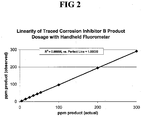
- FIG 2 illustrates the linearity and predictability of fluorescence where Rhodamine B base was used as the inert fluorescent tracer (about 0.006% wt/wt) in Corrosion Inhibitor B and added to fuel ethanol.
- Excitation wavelength was 540 nm and emission wavelength was 560 nm.
- Table 8 below illustrates a nonexhaustive list various excitation and emission wavelength ranges that may be used in the method of the invention. The list encompasses all of the described fluorescent components of the additive composition including an inherent or intrinsic fluorescent component, an inert fluorescent tracer, or a component that is reacted to become fluorescent. Table 8 Excitation Range Emission Range Ultraviolet light Ultraviolet light Ultraviolet light Visible light Visible light Visible light Visible light Near infrared light Near infrared light Near infrared light
Landscapes
- Health & Medical Sciences (AREA)
- Chemical & Material Sciences (AREA)
- Life Sciences & Earth Sciences (AREA)
- Immunology (AREA)
- Physics & Mathematics (AREA)
- Pathology (AREA)
- Biochemistry (AREA)
- General Health & Medical Sciences (AREA)
- General Physics & Mathematics (AREA)
- Analytical Chemistry (AREA)
- Chemical Kinetics & Catalysis (AREA)
- Engineering & Computer Science (AREA)
- Nuclear Medicine, Radiotherapy & Molecular Imaging (AREA)
- General Chemical & Material Sciences (AREA)
- Oil, Petroleum & Natural Gas (AREA)
- Food Science & Technology (AREA)
- Medicinal Chemistry (AREA)
- Molecular Biology (AREA)
- Optics & Photonics (AREA)
- Liquid Carbonaceous Fuels (AREA)
- Investigating, Analyzing Materials By Fluorescence Or Luminescence (AREA)
Claims (12)
- Verfahren zum Überwachen und Optimieren der Konzentration einer Hilfsstoffzusammensetzung in einem Kraftstoffethanol und Bestimmen eines Gesamtethanolgehalts in einer Kraftstoffethanolzusammensetzung,
wobei die Hilfsstoffzusammensetzung ein Denaturierungsmittel kombiniert mit einem Korrosionsinhibitor umfasst, wobei das Verfahren Folgendes umfasst:(a) Zusetzen eines inerten fluoreszierenden Tracers zu dem Korrosionsinhibitor, um eine ermittelte Korrosionsinhibitorformulierung auszubilden, wobei die ermittelte Korrosionsinhibitorformulierung dann mit dem Denaturierungsmittel kombiniert wird, um die Hilfsstoffzusammensetzung auszubilden;(b) Zusetzen einer bekannten Menge der Hilfsstoffzusammensetzung zu dem Kraftstoffethanol, um ein behandeltes Kraftstoffethanol zu erzeugen, wobei die bekannte Menge berechnet wird, um einen optimalen Konzentrationsbereich für die Hilfsstoffzusammensetzung in dem behandelten Kraftstoffethanol bereitzustellen, und wobei der inerte fluoreszierende Tracer Rhodamin B Base ist;(c) Messen des Fluoreszenzsignals für den inerten fluoreszierenden Tracer in dem behandelten Kraftstoffethanol an einem Zeitpunkt anschließend an das Zusetzen der bekannten Menge der Hilfsstoffzusammensetzung;(d) Bestimmen der Konzentration der Hilfsstoffzusammensetzung in dem behandelten Kraftstoffethanol basierend auf dem gemessenen Fluoreszenzsignal des inerten fluoreszierenden Tracers an dem anschließenden Zeitpunkt;(e) wenn die bestimmte Konzentration der Hilfsstoffzusammensetzung über dem optimalen Konzentrationsbereich liegt, Verdünnen des behandelten Kraftstoffethanols durch Zusetzen eines bekannten zusätzlichen Volumens des Kraftstoffethanols, wobei das zusätzliche Volumen berechnet wird, um die Konzentration der Hilfsstoffzusammensetzung in dem behandelten Kraftstoffethanol in den optimalen Konzentrationsbereich zu bringen; und(f) wenn die bestimmte Konzentration der Hilfsstoffzusammensetzung unter dem optimalen Konzentrationsbereich liegt, Zusetzen einer zusätzlichen bekannten Menge der Hilfsstoffzusammensetzung, wobei die zusätzliche bekannte Menge berechnet wird, um die Konzentration der Hilfsstoffzusammensetzung in dem behandelten Kraftstoffethanol in den optimalen Konzentrationsbereich zu bringen,
wobei das behandelte Kraftstoffethanol mit Benzin gemischt wird, um eine Kraftstoffethanolzusammensetzung auszubilden, und wobei das Fluoreszenzsignal verwendet wird, um den Gesamtethanolgehalt in der Kraftstoffethanolzusammensetzung zu bestimmen. - Verfahren nach Anspruch 1, wobei einer oder mehrere der Schritte (a) bis (e) wiederholt werden, bis die bestimmte Konzentration der Hilfsstoffzusammensetzung innerhalb des optimalen Konzentrationsbereiches liegt.
- Verfahren nach Anspruch 1, wobei die Hilfsstoffzusammensetzung einen Korrosionsinhibitor und ein Denaturierungsmittel beinhaltet, und das das Messen des Fluoreszenzsignals beinhaltet: (i) nachdem der Korrosionsinhibitor zugesetzt wird und bevor das Denaturierungsmittel zugesetzt wird; (ii) nachdem der Korrosionsinhibitor und das Denaturierungsmittel getrennt zugesetzt werden; und (iii) nachdem eine Mischung des Korrosionsinhibitors und des Denaturierungsmittels zugesetzt wird.
- Verfahren nach Anspruch 1, wobei ein Anregungs- und Emissionswellenlängenbereich für das Messen des Fluoreszenzsignal der Komponente aus der Gruppe ausgewählt ist, die aus Folgendem besteht: Ultraviolettlichtanregung und Ultraviolettlichtemission; Ultraviolettlichtanregung und Sichtbarlichtemission; Sichtbarlichtanregung und Sichtbarlichtemission; Sichtbarlichtanregung und Nahinfrarotemission; und Nahinfrarotanregung und Nahinfrarotemission.
- Verfahren nach Anspruch 1, das das Messen des Fluoreszenzsignals unter Verwendung einer Probe beinhaltet, die aus der Gruppe abgeleitet ist, die aus Folgendem besteht: Stichprobe; Nebenstromprobe; Inline-Probe; Massemessung; oder Kombinationen davon.
- Verfahren nach Anspruch 1, das ein Betreiben des Verfahrens mit einem Steuerschema beinhaltet, das aus der Gruppe ausgewählt ist, die aus Folgendem besteht: handbetrieben; automatisch; proportional-integrativ-derivativ oder ein anderes elektronisches/Computersteuern; Steuern basierend auf der Änderungsrate der gemessenen Signale im Laufe der Zeit; und Kombinationen davon.
- Verfahren nach Anspruch 1, wobei die Komponente das Fluoreszenzsignal nicht inhärent bereitstellt, und das das chemische Derivatisieren der Komponente in einer Stichprobe mit einem Molekülteil beinhaltet, um der Komponente zu ermöglichen, das Fluoreszenzsignal bereitzustellen, wobei die chemische Derivatisierung optional eine kovalente Bindung oder Komplexbildung zwischen der Komponente und dem Molekülteil ergibt.
- Verfahren nach Anspruch 1, wobei die Hilfsstoffzusammensetzung mehrere zusätzliche Verbindungen beinhaltet.
- Verfahren nach Anspruch 1, das das fortlaufende oder intermittierende Messen des Fluoreszenzsignals der Komponente beinhaltet oder das Messen des Fluoreszenzsignals der Komponente an mehreren Zeitpunkten beinhaltet.
- Verfahren nach Anspruch 1, das das Entfernen einer Probe des behandelten Kraftstoffethanols nach dem anschließenden Zeitpunkt, entweder automatisch oder manuell, und das Messen des Fluoreszenzsignals der Komponente beinhaltet.
- Verfahren nach Anspruch 1, das das Betreiben des Verfahrens über ein Netzwerk beinhaltet, wobei das Netzwerk einen oder mehrere Sensoren, Steuerungen, digitale Speichermedien und/oder Kommunikationsmittel umfasst, wobei das Netzwerk optional ein Internet ist.
- Digitales Speichermedium mit darauf gespeicherten computerausführbaren Anweisungen, wobei die Anweisungen betriebsfähig sind, um das Verfahren nach Anspruch 1 auszuführen.
Applications Claiming Priority (2)
| Application Number | Priority Date | Filing Date | Title |
|---|---|---|---|
| US12/143,400 US20090319195A1 (en) | 2008-06-20 | 2008-06-20 | Method of monitoring and optimizing additive concentration in fuel ethanol |
| PCT/US2009/047964 WO2009155524A1 (en) | 2008-06-20 | 2009-06-19 | Method of monitoring and optimizing additive concentration in fuel ethanol |
Publications (2)
| Publication Number | Publication Date |
|---|---|
| EP2304429A1 EP2304429A1 (de) | 2011-04-06 |
| EP2304429B1 true EP2304429B1 (de) | 2020-06-17 |
Family
ID=40983369
Family Applications (1)
| Application Number | Title | Priority Date | Filing Date |
|---|---|---|---|
| EP09767833.8A Active EP2304429B1 (de) | 2008-06-20 | 2009-06-19 | Verfahren zur überwachung und optimierung der additivkonzentration in brennstoff-ethanol |
Country Status (5)
| Country | Link |
|---|---|
| US (2) | US20090319195A1 (de) |
| EP (1) | EP2304429B1 (de) |
| AR (1) | AR072270A1 (de) |
| CA (1) | CA2724760C (de) |
| WO (1) | WO2009155524A1 (de) |
Families Citing this family (16)
| Publication number | Priority date | Publication date | Assignee | Title |
|---|---|---|---|---|
| US8276549B2 (en) * | 2007-08-17 | 2012-10-02 | GM Global Technology Operations LLC | Flexible fuel variable boost supercharged engine |
| US20090319195A1 (en) | 2008-06-20 | 2009-12-24 | Hoots John E | Method of monitoring and optimizing additive concentration in fuel ethanol |
| CA2812113C (en) * | 2010-09-28 | 2020-07-14 | Authentix, Inc. | Determining the quantity of a taggant in a liquid sample |
| US9995681B2 (en) * | 2010-09-28 | 2018-06-12 | Authentix, Inc. | Determining the quantity of a taggant in a liquid sample |
| CA2842716C (en) * | 2011-09-23 | 2015-05-26 | Nalco Company | Fluorometric method for monitoring surface additives in a papermaking process |
| FR2985316B1 (fr) * | 2012-01-04 | 2015-08-07 | Rhodia Operations | Procede pour le diagnostic externe du dysfonctionnement d'un dispositif d'additivation d'un additif dans un carburant pour un vehicule |
| GB201205990D0 (en) | 2012-04-03 | 2012-05-16 | Formatex Offshore S A L | A method of determining the suitability of a fuel for use in an engine and a composition for use in such a method |
| US9194858B2 (en) * | 2012-05-11 | 2015-11-24 | Polaris Sensor Technologies, Inc. | System for measuring the concentration of an additive in a mixture |
| US9541502B2 (en) | 2014-10-03 | 2017-01-10 | Formatex (Offshore) S.A.L. | Method of determining the suitability of a fuel for use in an engine and a composition for use in such a method |
| US10466175B2 (en) | 2015-02-10 | 2019-11-05 | Ecolab Usa Inc. | Corrosion inhibitors and kinetic hydrate inhibitors |
| WO2017093913A1 (en) * | 2015-11-30 | 2017-06-08 | Sabic Global Technologies B.V. | Process for enhancing gasoline octane boosters, gasoline boosters, and gasolines |
| US10851725B2 (en) * | 2018-12-18 | 2020-12-01 | Caterpillar Inc. | Fuel content detection based on a measurement from a sensor and a model estimation of the measurement |
| GB201908912D0 (en) | 2019-06-21 | 2019-08-07 | Innospec Ltd | Compositions and methods and uses relating thereto |
| US12169192B2 (en) * | 2020-11-02 | 2024-12-17 | Afton Chemical Corporation | Methods of identifying a hydrocarbon fuel |
| GB202205344D0 (en) * | 2022-04-12 | 2022-05-25 | Rolls Royce Plc | Calorific value |
| DE102024134018A1 (de) | 2024-11-20 | 2026-05-21 | Volkswagen Aktiengesellschaft | Verfahren und Kraftstoffidentifikationsvorrichtung zur Identifikation eines von einem Fahrzeug in einem Tankvorgang getankten und/oder zu tankenden Kraftstoffgemischs |
Citations (3)
| Publication number | Priority date | Publication date | Assignee | Title |
|---|---|---|---|---|
| US5128419A (en) * | 1990-08-20 | 1992-07-07 | Nalco Chemical Company | Synthesis of tagged polymers by post-polymerization (trans) amidation reaction |
| WO2005052560A1 (en) * | 2003-11-19 | 2005-06-09 | Johnson Matthey Plc | Apparatus and method for identifying a liquid product |
| US20070204505A1 (en) * | 2006-03-02 | 2007-09-06 | Novus International Inc. | Gasoline fuel compositions having increased oxidative stability |
Family Cites Families (47)
| Publication number | Priority date | Publication date | Assignee | Title |
|---|---|---|---|---|
| GB1065995A (en) * | 1963-12-06 | 1967-04-19 | Geigy Uk Ltd | Benzotriazoles and their production |
| US4406811A (en) * | 1980-01-16 | 1983-09-27 | Nalco Chemical Company | Composition and method for controlling corrosion in aqueous systems |
| US4426208A (en) * | 1981-11-02 | 1984-01-17 | Ethyl Corporation | Corrosion inhibitors for alcohol-based fuels |
| US4783314A (en) * | 1987-02-26 | 1988-11-08 | Nalco Chemical Company | Fluorescent tracers - chemical treatment monitors |
| US5009799A (en) | 1988-02-16 | 1991-04-23 | Nalco Chemical Company | Inorganic acid solution viscosifier and corrosion inhibitor and method |
| US4992380A (en) | 1988-10-14 | 1991-02-12 | Nalco Chemical Company | Continuous on-stream monitoring of cooling tower water |
| US4964468A (en) | 1989-08-08 | 1990-10-23 | Nalco Chemical Company | Method of inhibiting corrosion |
| US4994197A (en) * | 1989-12-18 | 1991-02-19 | Mobil Oil Corporation | Triazole compositions as fuel and lube additives |
| US5171450A (en) * | 1991-03-20 | 1992-12-15 | Nalco Chemical Company | Monitoring and dosage control of tagged polymers in cooling water systems |
| US5225679A (en) * | 1992-01-24 | 1993-07-06 | Boston Advanced Technologies, Inc. | Methods and apparatus for determining hydrocarbon fuel properties |
| US5278074A (en) * | 1992-04-22 | 1994-01-11 | Nalco Chemical Company | Method of monitoring and controlling corrosion inhibitor dosage in aqueous systems |
| US5358873A (en) * | 1992-07-27 | 1994-10-25 | Atlantic Richfield Company | Method for determining adulteration of gasolines |
| CN1069162C (zh) * | 1994-05-02 | 2001-08-08 | 诺尔科化学公司 | 用作改进的抗微生物剂的荧光杀生物剂组合物 |
| EP0703451A3 (de) * | 1994-09-26 | 1998-07-29 | Nalco Chemical Company | Überwachung von Prozessflüssigkeiten in Papierherstellungssystemen |
| US5843783A (en) * | 1994-11-04 | 1998-12-01 | Amoco Corporation | Tagging hydrocarbons for subsequent identification |
| US5744665A (en) | 1995-06-08 | 1998-04-28 | Exxon Production Research Company | Maleimide copolymers and method for inhibiting hydrate formation |
| ZA984976B (en) | 1997-06-11 | 1999-04-19 | Nalco Chemical Co | Solid-state fluorometer and methods of use therefore |
| US6487994B2 (en) * | 1999-07-23 | 2002-12-03 | Supercritical Combustion Corporation | Sub-critical water-fuel composition and combustion system |
| GB9924358D0 (en) * | 1999-10-14 | 1999-12-15 | Brad Chem Technology Ltd | Corrosion inhibiting compositions |
| US6866797B1 (en) | 2000-08-03 | 2005-03-15 | Bj Services Company | Corrosion inhibitors and methods of use |
| US6472219B1 (en) | 2000-08-31 | 2002-10-29 | Ondeo Nalco Company | Use of tracers to monitor application of treatment products to cut flowers |
| US6670617B2 (en) * | 2001-06-28 | 2003-12-30 | Ondeo Nalco Company | Mirror fluorometer |
| US20040157334A1 (en) * | 2002-08-12 | 2004-08-12 | Barashkov Nikolay N. | Method for determination of ethanol concentration in an aqueous solution containing an alcoholic beverage |
| US7057050B2 (en) | 2003-04-11 | 2006-06-06 | Nalco Energy Services L.P. | Imidazoline corrosion inhibitors |
| US20050008532A1 (en) * | 2003-07-11 | 2005-01-13 | Jenkins Brian V. | Method of inhibiting corrosion of copper plated or metallized surfaces and circuitry during semiconductor manufacturing processes |
| US20050025660A1 (en) * | 2003-07-31 | 2005-02-03 | Hoots John E. | Method of tracing corrosive materials |
| US6966213B2 (en) * | 2004-01-28 | 2005-11-22 | Nalco Company | Rapid method for detecting leaks of hydraulic fluids in production plants |
| DE102004044717B8 (de) * | 2004-09-10 | 2010-12-16 | BAM Bundesanstalt für Materialforschung und -prüfung | Verfahren und Kit zur Kalibrierung eines Photolumineszenzmesssystems |
| US7311144B2 (en) | 2004-10-12 | 2007-12-25 | Greg Allen Conrad | Apparatus and method for increasing well production using surfactant injection |
| US20080168708A1 (en) * | 2007-01-11 | 2008-07-17 | Cunningham Lawrence J | Method and compositions for reducing deposits in engines combusting ethanol-containing fuels and a corrosion inhibitor |
| US20080308770A1 (en) | 2007-06-14 | 2008-12-18 | Laxmikant Tiwari | Mono and bis-ester derivatives of pyridinium and quinolinium compounds as environmentally friendly corrosion inhibitors |
| US8551925B2 (en) | 2007-11-15 | 2013-10-08 | Nalco Company | Imidazoline-based heterocyclic foamers for downhole injection |
| US7951754B2 (en) | 2007-12-07 | 2011-05-31 | Nalco Company | Environmentally friendly bis-quaternary compounds for inhibiting corrosion and removing hydrocarbonaceous deposits in oil and gas applications |
| US8250931B2 (en) * | 2008-03-28 | 2012-08-28 | Global Process Technologies, Inc. | Methods and compositions for inhibiting corrosion in non-aqueous, non-conductive liquids |
| US20090319195A1 (en) | 2008-06-20 | 2009-12-24 | Hoots John E | Method of monitoring and optimizing additive concentration in fuel ethanol |
| US8334240B2 (en) | 2008-10-06 | 2012-12-18 | Nalco Company | Compositions and methods for inhibiting the agglomeration of hydrates in a process |
| US8105987B2 (en) | 2008-10-06 | 2012-01-31 | Nalco Company | Corrosion inhibitors for an aqueous medium |
| US8105988B2 (en) | 2008-10-06 | 2012-01-31 | Nalco Company | Corrosion inhibitors for a fluid |
| US8329620B2 (en) | 2008-10-06 | 2012-12-11 | Nalco Company | Compositions and methods for inhibiting the agglomeration of hydrates |
| US10392573B2 (en) | 2008-10-17 | 2019-08-27 | Ecolab Usa Inc. | Method of controlling gas hydrates in fluid systems |
| US8921478B2 (en) | 2008-10-17 | 2014-12-30 | Nalco Company | Method of controlling gas hydrates in fluid systems |
| US8288323B2 (en) | 2009-03-02 | 2012-10-16 | Nalco Company | Compositions containing amide surfactants and methods for inhibiting the formation of hydrate agglomerates |
| US7989403B2 (en) | 2009-03-02 | 2011-08-02 | Nalco Company | Corrosion inhibitors containing amide surfactants for a fluid |
| US8911615B2 (en) | 2010-04-08 | 2014-12-16 | William Marsh Rice University | Recovery and separation of crude oil and water from emulsions |
| US8618027B2 (en) | 2010-12-08 | 2013-12-31 | Nalco Company | Corrosion inhibitors for oil and gas applications |
| US8618025B2 (en) | 2010-12-16 | 2013-12-31 | Nalco Company | Composition and method for reducing hydrate agglomeration |
| US20150034319A1 (en) | 2013-07-31 | 2015-02-05 | Baker Hughes Incorporated | H2s scavengers with synergistic corrosion inhibition |
-
2008
- 2008-06-20 US US12/143,400 patent/US20090319195A1/en not_active Abandoned
-
2009
- 2009-06-19 AR ARP090102271A patent/AR072270A1/es active IP Right Grant
- 2009-06-19 EP EP09767833.8A patent/EP2304429B1/de active Active
- 2009-06-19 CA CA2724760A patent/CA2724760C/en active Active
- 2009-06-19 WO PCT/US2009/047964 patent/WO2009155524A1/en not_active Ceased
-
2015
- 2015-04-06 US US14/679,575 patent/US10436719B2/en active Active
Patent Citations (3)
| Publication number | Priority date | Publication date | Assignee | Title |
|---|---|---|---|---|
| US5128419A (en) * | 1990-08-20 | 1992-07-07 | Nalco Chemical Company | Synthesis of tagged polymers by post-polymerization (trans) amidation reaction |
| WO2005052560A1 (en) * | 2003-11-19 | 2005-06-09 | Johnson Matthey Plc | Apparatus and method for identifying a liquid product |
| US20070204505A1 (en) * | 2006-03-02 | 2007-09-06 | Novus International Inc. | Gasoline fuel compositions having increased oxidative stability |
Non-Patent Citations (1)
| Title |
|---|
| KELLY G. CASEY ET AL: "Effect of solvent polarity on nonradiative processes in xanthene dyes: Rhodamine B in normal alcohols", JOURNAL OF PHYSICAL CHEMISTRY, vol. 92, no. 23, 1 November 1988 (1988-11-01), US, pages 6590 - 6594, XP055559577, ISSN: 0022-3654, DOI: 10.1021/j100334a023 * |
Also Published As
| Publication number | Publication date |
|---|---|
| CA2724760C (en) | 2018-02-27 |
| WO2009155524A1 (en) | 2009-12-23 |
| US10436719B2 (en) | 2019-10-08 |
| CA2724760A1 (en) | 2009-12-23 |
| US20150212007A1 (en) | 2015-07-30 |
| US20090319195A1 (en) | 2009-12-24 |
| AR072270A1 (es) | 2010-08-18 |
| EP2304429A1 (de) | 2011-04-06 |
Similar Documents
| Publication | Publication Date | Title |
|---|---|---|
| US10436719B2 (en) | Method of monitoring and optimizing additive concentration in fuel ethanol | |
| Botto et al. | Use of an ultrasonic nebulizer with membrane desolvation for analysis of volatile solvents by inductively coupled plasma atomic emission spectrometry | |
| BR112019015343B1 (pt) | Mistura controlada de biodiesel em fluxos de destilados | |
| CN103238060A (zh) | 用于测定减轻原油蒸馏装置腐蚀的系统参数的方法和装置 | |
| CN113092457A (zh) | 适用于复杂环境水体中亚硝酸盐氮的在线准确检测方法 | |
| CN102590123A (zh) | 枸橼酸铋钾药物中铋含量的检测方法 | |
| WO2025007645A1 (zh) | 一种检测己二胺的方法 | |
| Snigur et al. | A tristimulus colorimetric study of the acid–base properties of 6, 7-dihydroxybenzopyrylium chlorides in solutions | |
| US5397708A (en) | Method for detection of sulfides | |
| CN109406684B (zh) | 一种测定色氨酸的杂质b、c、d含量的检测方法 | |
| CN1130700A (zh) | 荧光示踪剂在制浆和造纸过程中的诊断应用 | |
| Pavlova et al. | Determination of total nitrogen content by different approaches in petroleum matrices | |
| CA2683295A1 (en) | Method of monitoring and optimizing denaturant concentration in fuel ethanol | |
| CN104964935A (zh) | 一种油溶性标识剂及其在燃油和燃油添加剂中的应用 | |
| CN110261335A (zh) | 一种测定聚环氧琥珀酸含量的方法 | |
| Shishov et al. | Simultaneous cyclic-injection spectrophotometric determination of aluminum and iron in petroleum products | |
| CN1560607A (zh) | 一种快速测定果汁及饮料中钠离子含量的方法 | |
| CN114894736A (zh) | 一种氯化物型卤水中硝酸根的测定方法 | |
| US10351789B2 (en) | Method of improving the accuracy when quantifying fluorescence markers in fuels | |
| RU2768892C2 (ru) | Способ количественного определения многофункциональной моющей присадки в бензинах методом инфракрасной спектрометрии с предварительным концентрированием | |
| CN111257251A (zh) | 一种测定钾含量的方法 | |
| JPH0894520A (ja) | 蛍光物質による冷却水系水処理剤濃度及び保有水量の測定方法 | |
| RU2861464C1 (ru) | Способ качественного и количественного определения моющих присадок в моторных топливах (варианты) | |
| Lambert et al. | A review of oil-in-water monitoring techniques | |
| US11474045B2 (en) | Method and device for the determination of film forming amines in a liquid |
Legal Events
| Date | Code | Title | Description |
|---|---|---|---|
| PUAI | Public reference made under article 153(3) epc to a published international application that has entered the european phase |
Free format text: ORIGINAL CODE: 0009012 |
|
| 17P | Request for examination filed |
Effective date: 20110120 |
|
| AK | Designated contracting states |
Kind code of ref document: A1 Designated state(s): AT BE BG CH CY CZ DE DK EE ES FI FR GB GR HR HU IE IS IT LI LT LU LV MC MK MT NL NO PL PT RO SE SI SK TR |
|
| AX | Request for extension of the european patent |
Extension state: AL BA RS |
|
| DAX | Request for extension of the european patent (deleted) | ||
| 17Q | First examination report despatched |
Effective date: 20150520 |
|
| STAA | Information on the status of an ep patent application or granted ep patent |
Free format text: STATUS: EXAMINATION IS IN PROGRESS |
|
| GRAP | Despatch of communication of intention to grant a patent |
Free format text: ORIGINAL CODE: EPIDOSNIGR1 |
|
| STAA | Information on the status of an ep patent application or granted ep patent |
Free format text: STATUS: GRANT OF PATENT IS INTENDED |
|
| INTG | Intention to grant announced |
Effective date: 20200109 |
|
| GRAS | Grant fee paid |
Free format text: ORIGINAL CODE: EPIDOSNIGR3 |
|
| GRAA | (expected) grant |
Free format text: ORIGINAL CODE: 0009210 |
|
| STAA | Information on the status of an ep patent application or granted ep patent |
Free format text: STATUS: THE PATENT HAS BEEN GRANTED |
|
| AK | Designated contracting states |
Kind code of ref document: B1 Designated state(s): AT BE BG CH CY CZ DE DK EE ES FI FR GB GR HR HU IE IS IT LI LT LU LV MC MK MT NL NO PL PT RO SE SI SK TR |
|
| REG | Reference to a national code |
Ref country code: GB Ref legal event code: FG4D |
|
| REG | Reference to a national code |
Ref country code: CH Ref legal event code: EP |
|
| REG | Reference to a national code |
Ref country code: DE Ref legal event code: R096 Ref document number: 602009062261 Country of ref document: DE |
|
| REG | Reference to a national code |
Ref country code: IE Ref legal event code: FG4D |
|
| REG | Reference to a national code |
Ref country code: AT Ref legal event code: REF Ref document number: 1281950 Country of ref document: AT Kind code of ref document: T Effective date: 20200715 |
|
| PG25 | Lapsed in a contracting state [announced via postgrant information from national office to epo] |
Ref country code: SE Free format text: LAPSE BECAUSE OF FAILURE TO SUBMIT A TRANSLATION OF THE DESCRIPTION OR TO PAY THE FEE WITHIN THE PRESCRIBED TIME-LIMIT Effective date: 20200617 Ref country code: GR Free format text: LAPSE BECAUSE OF FAILURE TO SUBMIT A TRANSLATION OF THE DESCRIPTION OR TO PAY THE FEE WITHIN THE PRESCRIBED TIME-LIMIT Effective date: 20200918 Ref country code: NO Free format text: LAPSE BECAUSE OF FAILURE TO SUBMIT A TRANSLATION OF THE DESCRIPTION OR TO PAY THE FEE WITHIN THE PRESCRIBED TIME-LIMIT Effective date: 20200917 Ref country code: FI Free format text: LAPSE BECAUSE OF FAILURE TO SUBMIT A TRANSLATION OF THE DESCRIPTION OR TO PAY THE FEE WITHIN THE PRESCRIBED TIME-LIMIT Effective date: 20200617 Ref country code: LT Free format text: LAPSE BECAUSE OF FAILURE TO SUBMIT A TRANSLATION OF THE DESCRIPTION OR TO PAY THE FEE WITHIN THE PRESCRIBED TIME-LIMIT Effective date: 20200617 |
|
| REG | Reference to a national code |
Ref country code: LT Ref legal event code: MG4D |
|
| REG | Reference to a national code |
Ref country code: NL Ref legal event code: MP Effective date: 20200617 |
|
| PG25 | Lapsed in a contracting state [announced via postgrant information from national office to epo] |
Ref country code: BG Free format text: LAPSE BECAUSE OF FAILURE TO SUBMIT A TRANSLATION OF THE DESCRIPTION OR TO PAY THE FEE WITHIN THE PRESCRIBED TIME-LIMIT Effective date: 20200917 Ref country code: HR Free format text: LAPSE BECAUSE OF FAILURE TO SUBMIT A TRANSLATION OF THE DESCRIPTION OR TO PAY THE FEE WITHIN THE PRESCRIBED TIME-LIMIT Effective date: 20200617 Ref country code: LV Free format text: LAPSE BECAUSE OF FAILURE TO SUBMIT A TRANSLATION OF THE DESCRIPTION OR TO PAY THE FEE WITHIN THE PRESCRIBED TIME-LIMIT Effective date: 20200617 |
|
| REG | Reference to a national code |
Ref country code: AT Ref legal event code: MK05 Ref document number: 1281950 Country of ref document: AT Kind code of ref document: T Effective date: 20200617 |
|
| PG25 | Lapsed in a contracting state [announced via postgrant information from national office to epo] |
Ref country code: NL Free format text: LAPSE BECAUSE OF FAILURE TO SUBMIT A TRANSLATION OF THE DESCRIPTION OR TO PAY THE FEE WITHIN THE PRESCRIBED TIME-LIMIT Effective date: 20200617 |
|
| REG | Reference to a national code |
Ref country code: DE Ref legal event code: R119 Ref document number: 602009062261 Country of ref document: DE |
|
| PG25 | Lapsed in a contracting state [announced via postgrant information from national office to epo] |
Ref country code: AT Free format text: LAPSE BECAUSE OF FAILURE TO SUBMIT A TRANSLATION OF THE DESCRIPTION OR TO PAY THE FEE WITHIN THE PRESCRIBED TIME-LIMIT Effective date: 20200617 Ref country code: EE Free format text: LAPSE BECAUSE OF FAILURE TO SUBMIT A TRANSLATION OF THE DESCRIPTION OR TO PAY THE FEE WITHIN THE PRESCRIBED TIME-LIMIT Effective date: 20200617 Ref country code: CZ Free format text: LAPSE BECAUSE OF FAILURE TO SUBMIT A TRANSLATION OF THE DESCRIPTION OR TO PAY THE FEE WITHIN THE PRESCRIBED TIME-LIMIT Effective date: 20200617 Ref country code: RO Free format text: LAPSE BECAUSE OF FAILURE TO SUBMIT A TRANSLATION OF THE DESCRIPTION OR TO PAY THE FEE WITHIN THE PRESCRIBED TIME-LIMIT Effective date: 20200617 Ref country code: ES Free format text: LAPSE BECAUSE OF FAILURE TO SUBMIT A TRANSLATION OF THE DESCRIPTION OR TO PAY THE FEE WITHIN THE PRESCRIBED TIME-LIMIT Effective date: 20200617 Ref country code: PT Free format text: LAPSE BECAUSE OF FAILURE TO SUBMIT A TRANSLATION OF THE DESCRIPTION OR TO PAY THE FEE WITHIN THE PRESCRIBED TIME-LIMIT Effective date: 20201019 Ref country code: IT Free format text: LAPSE BECAUSE OF FAILURE TO SUBMIT A TRANSLATION OF THE DESCRIPTION OR TO PAY THE FEE WITHIN THE PRESCRIBED TIME-LIMIT Effective date: 20200617 |
|
| REG | Reference to a national code |
Ref country code: CH Ref legal event code: PL |
|
| PG25 | Lapsed in a contracting state [announced via postgrant information from national office to epo] |
Ref country code: IS Free format text: LAPSE BECAUSE OF FAILURE TO SUBMIT A TRANSLATION OF THE DESCRIPTION OR TO PAY THE FEE WITHIN THE PRESCRIBED TIME-LIMIT Effective date: 20201017 Ref country code: PL Free format text: LAPSE BECAUSE OF FAILURE TO SUBMIT A TRANSLATION OF THE DESCRIPTION OR TO PAY THE FEE WITHIN THE PRESCRIBED TIME-LIMIT Effective date: 20200617 Ref country code: SK Free format text: LAPSE BECAUSE OF FAILURE TO SUBMIT A TRANSLATION OF THE DESCRIPTION OR TO PAY THE FEE WITHIN THE PRESCRIBED TIME-LIMIT Effective date: 20200617 |
|
| PG25 | Lapsed in a contracting state [announced via postgrant information from national office to epo] |
Ref country code: MC Free format text: LAPSE BECAUSE OF FAILURE TO SUBMIT A TRANSLATION OF THE DESCRIPTION OR TO PAY THE FEE WITHIN THE PRESCRIBED TIME-LIMIT Effective date: 20200617 Ref country code: LU Free format text: LAPSE BECAUSE OF NON-PAYMENT OF DUE FEES Effective date: 20200619 |
|
| REG | Reference to a national code |
Ref country code: BE Ref legal event code: MM Effective date: 20200630 |
|
| PLBE | No opposition filed within time limit |
Free format text: ORIGINAL CODE: 0009261 |
|
| STAA | Information on the status of an ep patent application or granted ep patent |
Free format text: STATUS: NO OPPOSITION FILED WITHIN TIME LIMIT |
|
| PG25 | Lapsed in a contracting state [announced via postgrant information from national office to epo] |
Ref country code: CH Free format text: LAPSE BECAUSE OF NON-PAYMENT OF DUE FEES Effective date: 20200630 Ref country code: DK Free format text: LAPSE BECAUSE OF FAILURE TO SUBMIT A TRANSLATION OF THE DESCRIPTION OR TO PAY THE FEE WITHIN THE PRESCRIBED TIME-LIMIT Effective date: 20200617 Ref country code: IE Free format text: LAPSE BECAUSE OF NON-PAYMENT OF DUE FEES Effective date: 20200619 Ref country code: LI Free format text: LAPSE BECAUSE OF NON-PAYMENT OF DUE FEES Effective date: 20200630 |
|
| 26N | No opposition filed |
Effective date: 20210318 |
|
| GBPC | Gb: european patent ceased through non-payment of renewal fee |
Effective date: 20200917 |
|
| PG25 | Lapsed in a contracting state [announced via postgrant information from national office to epo] |
Ref country code: SI Free format text: LAPSE BECAUSE OF FAILURE TO SUBMIT A TRANSLATION OF THE DESCRIPTION OR TO PAY THE FEE WITHIN THE PRESCRIBED TIME-LIMIT Effective date: 20200617 Ref country code: DE Free format text: LAPSE BECAUSE OF NON-PAYMENT OF DUE FEES Effective date: 20210101 Ref country code: BE Free format text: LAPSE BECAUSE OF NON-PAYMENT OF DUE FEES Effective date: 20200630 |
|
| PG25 | Lapsed in a contracting state [announced via postgrant information from national office to epo] |
Ref country code: FR Free format text: LAPSE BECAUSE OF NON-PAYMENT OF DUE FEES Effective date: 20200817 |
|
| PG25 | Lapsed in a contracting state [announced via postgrant information from national office to epo] |
Ref country code: GB Free format text: LAPSE BECAUSE OF NON-PAYMENT OF DUE FEES Effective date: 20200917 |
|
| PG25 | Lapsed in a contracting state [announced via postgrant information from national office to epo] |
Ref country code: TR Free format text: LAPSE BECAUSE OF FAILURE TO SUBMIT A TRANSLATION OF THE DESCRIPTION OR TO PAY THE FEE WITHIN THE PRESCRIBED TIME-LIMIT Effective date: 20200617 Ref country code: MT Free format text: LAPSE BECAUSE OF FAILURE TO SUBMIT A TRANSLATION OF THE DESCRIPTION OR TO PAY THE FEE WITHIN THE PRESCRIBED TIME-LIMIT Effective date: 20200617 Ref country code: CY Free format text: LAPSE BECAUSE OF FAILURE TO SUBMIT A TRANSLATION OF THE DESCRIPTION OR TO PAY THE FEE WITHIN THE PRESCRIBED TIME-LIMIT Effective date: 20200617 |
|
| PG25 | Lapsed in a contracting state [announced via postgrant information from national office to epo] |
Ref country code: MK Free format text: LAPSE BECAUSE OF FAILURE TO SUBMIT A TRANSLATION OF THE DESCRIPTION OR TO PAY THE FEE WITHIN THE PRESCRIBED TIME-LIMIT Effective date: 20200617 |