EP2303218B1 - Intelligentes servogerät für ein mechanisches cpr-system - Google Patents
Intelligentes servogerät für ein mechanisches cpr-system Download PDFInfo
- Publication number
- EP2303218B1 EP2303218B1 EP09769733.8A EP09769733A EP2303218B1 EP 2303218 B1 EP2303218 B1 EP 2303218B1 EP 09769733 A EP09769733 A EP 09769733A EP 2303218 B1 EP2303218 B1 EP 2303218B1
- Authority
- EP
- European Patent Office
- Prior art keywords
- chest
- chest compression
- actuator
- compression
- waveform
- Prior art date
- Legal status (The legal status is an assumption and is not a legal conclusion. Google has not performed a legal analysis and makes no representation as to the accuracy of the status listed.)
- Active
Links
Images




Classifications
-
- A—HUMAN NECESSITIES
- A61—MEDICAL OR VETERINARY SCIENCE; HYGIENE
- A61H—PHYSICAL THERAPY APPARATUS, e.g. DEVICES FOR LOCATING OR STIMULATING REFLEX POINTS IN THE BODY; ARTIFICIAL RESPIRATION; MASSAGE; BATHING DEVICES FOR SPECIAL THERAPEUTIC OR HYGIENIC PURPOSES OR SPECIFIC PARTS OF THE BODY
- A61H31/00—Artificial respiration by a force applied to the chest; Heart stimulation, e.g. heart massage
- A61H31/004—Heart stimulation
-
- A—HUMAN NECESSITIES
- A61—MEDICAL OR VETERINARY SCIENCE; HYGIENE
- A61H—PHYSICAL THERAPY APPARATUS, e.g. DEVICES FOR LOCATING OR STIMULATING REFLEX POINTS IN THE BODY; ARTIFICIAL RESPIRATION; MASSAGE; BATHING DEVICES FOR SPECIAL THERAPEUTIC OR HYGIENIC PURPOSES OR SPECIFIC PARTS OF THE BODY
- A61H2201/00—Characteristics of apparatus not provided for in the preceding codes
- A61H2201/01—Constructive details
- A61H2201/0173—Means for preventing injuries
- A61H2201/018—By limiting the applied torque or force
Definitions
- the invention relates to the field of automated cardiopulmonary resuscitation apparatuses, and more specifically to a control for a chest compression actuator.
- Cardiopulmonary resuscitation is a well-known technique for increasing the chance for survival from cardiac arrest. However, it is very difficult to perform consistent high quality manual cardiopulmonary resuscitation. Since CPR quality is key for survival there is a strong drive to have a mechanical automated device to replace less reliable and long duration manual chest compressions. Automated CPR (A-CPR) systems were introduced in the market recently.
- A-CPR Automated CPR
- Patent application publication US 2007/0270724 A1 describes a servo motor for CPR that features a control of the compression wave form as applied to the patient. To this end US 2007/0270724 A1 proposes to adjust the set point wave form. This leads to improved therapy concerning both blood flow and avoidance of internal injuries, because the desired wave form can be chosen relatively close to upper limits that should never be exceeded.
- EP 1854444 describes a chest compression device comprising a power source, a compressing element connected to the power source and a controller which controls the motor so as to make the compressing element apply compressions with desired predefined characteristics.
- the motor controller comprises software to detect erroneous movement or lack of movement of the device and deactivates a motor power control to safeguard the "patient”.
- EP 1854444 discloses the use of sensors sensing the relevant characteristics of the patient as electrocardiogram, blood pressure, oxygen content of the blood or relevant features regarding the CPR.
- EP 1854444 also indicates that there may be provided feedback signals from the patient to the servo controller. However, there is no indication on what these feedback signals are and how they are provided.
- EP 1854444 specifies only the limits within the maximum speed of compression to avoid chest injuries or high speed limits to maximize patient blood flow. Thus, setting upper limits within the CPR operational range, independently from the chest compression action on to the patient.
- a servomotor and its control use a feed-forward part (how well does the actuator follow the commanded motion, i.e. signal sent in advance to the motor to have accurate following) and a disturbance control part (rejection of disturbances i.e. deviations from the desired motion, i.e. (accidental) deviations from the commanded motion).
- the feed-forward control part is an estimated actuator force-versus-time (or in this case current or voltage) which is needed to follow the desired motion as good as possible (i.e. within an average or maximum error).
- the feed-forward control is calculated once and a detailed model of the system and the servo system is required.
- the mechanical system comprising the chest of the patient and a chest compression actuator is subject to significant variations due to for example the stature of the patient, the placement of the actuator, and various other factors.
- the mechanical system is at least of second order which means that it is capable of oscillations.
- the mechanical system is also subject to overshoots. If these properties of the mechanical system are not properly taken in consideration, the oscillations and/or the overshoots may come dangerously close to the allowed limit or even exceed those limits. A major worry is injuries to the chest and thorax (broken ribs, sternum organ rupture).
- the mechanical properties of the chest and the thorax are subject to wide variations depending on the stature of the patient.
- the mechanical properties may even vary quite significantly during performing the cardio pulmonary resuscitation: The thorax becomes less stiff and full chest relaxation does not occur anymore.
- an automated cardiopulmonary resuscitation apparatus is presented in accordance with claim 1.
- the actuator driver comprising a controller that receives the measured values and a corresponding desired value and generates closed loop control signals for the chest compression actuator. It would be desirable to modify operating parameters that are easily alterable and have a certain degree of influence on the dynamic behavior or the response of the mechanical system. This concern is addressed in that the operating parameters of the actuator driver subject to the adaptive control comprise at least one among a gain of the controller and the desired value.
- the adaptive control comprising an iterative learning control that receives the measured values and a corresponding desired value, and generates control signals for the chest compression actuator in an iterative manner based on a previous control signal and the difference between the measured value and the desired value.
- the iterative learning control converges to a solution that assures a high degree of conformance between an actual output of the mechanical system chest-actuator and a desired wave form.
- this concern is addressed by the difference between the measured value and the desired value being differentiated with respect to time. The result of the differentiation tends to zero as the difference between the measured value and the desired value becomes more and more constant.
- Stability can be achieved for appropriate values of ⁇ .
- a signal is proposed that is transmitted from an adaptive control to an actuator driver of an automated Cardio Pulmonary Resuscitation system.
- the signal comprises instructions to the actuator driver to modify operating parameters that determine a dynamic behavior of a system comprising a chest of a patient and a chest compression actuator of the automated Cardio Pulmonary Resuscitation apparatus.
- the basic idea is to take into consideration the varying dynamic behavior of the mechanical system chest-actuator. Nevertheless, a theoretical model of the mechanical system is not needed. Automated cardio pulmonary resuscitation should start gently to avoid thorax damage. An adaptive gain of the controller settings is important (i.e. do not use too high gains initially, change gain during reanimation). A reliable estimation of feedforward input signal of the servo system is needed. An adaptive optimization of cardio pulmonary resuscitation by iterative learning control of the feedforward part of the control may contribute to a satisfactory performance of the system. The recommended compression pulse has to be followed very accurately or else severe body damage or reduced perfusion can result. Moreover, the adaptivity and self-learning of the system is presently not well understood in the CPR environment.
- Fig. 1 shows a schematic block diagram of an automated cardio pulmonary resuscitation apparatus according to a first aspect of the invention.
- the automated cardio resuscitation apparatus uses a chest compression actuator 102 that exerts a force on a human chest 104 by use of e.g. a pad and a piston.
- the chest 104 is not a part of the automated cardio pulmonary resuscitation apparatus and is represented by a mechanical model that approximates the mechanical behavior of the chest 104.
- the mechanical model can be represented by a spring and a damper connected in parallel.
- the movement of the pad, and consequently also the compression of the chest is detected by a physiological parameter sensor 106 that provides measurements for the actual chest compression y k .
- the measurements of the actual chest compression y k is detected by a physiological parameter sensor 106 that provides measurements for the actual chest compression y k .
- the chest compression actuator 102, the chest of the patient 104, the physiological parameter sensor 106, and the controller 112 form a closed loop control system.
- the mechanical properties of the chest 104 are subject to significant variations, not only from one patient to another, but also over time for a single patient.
- An automated cardio pulmonary resuscitation apparatus has to cope with a wide range of patient size and weight, with a large freedom in the shape of the compression pulse, and with low risk to damage the thorax and vital organs.
- the desired compression waveform has to be followed accurately without user intervention.
- the controller 112 is part of an actuator driver 110 that comprises some memory for operating parameters 113 and 114.
- Operating parameter 113 is the desired waveform y d (t) that is used as a setpoint signal for controller 112.
- Operating parameter 114 is the gain g of the controller 112.
- the operating parameters 113 and 114 are adjusted by an adaptive control 108 that receives the measurements of the actual compression waveform y k -as an input and analyses the measurements with respect to the quality of the actual compression waveform.
- the adaptive control 108 may compare certain properties of the actual compression waveform with preselected values such as the peak compression depth, the compression velocity, and the like. Adaptive control 108 might determine whether the preselected values or exceeded by the actual compression waveform y k .
- adaptive control 108 compare the actual compression waveform y k with prestored compression waveforms that are considered to be optimal, near-optimal and/or undesired. Based on the analysis adaptive control 108 provides an output on connection 109 to the actuator driver, and in particular to the section where the operating parameters 113 and 114 are stored. Other operating parameters besides the desired compression waveform y d (t) 113 and controller gain g 114 are also possible, such as the gains of the integrator part and the derivative part in a PID controller.
- the human thorax with its non-linear visco-elastic properties is schematically illustrated.
- the automated cardio pulmonary resuscitation apparatus consists of a pad, a transmission and motion conversion unit, e.g. from rotation to linear, a servo motor 102, an amplifier (not individually shown, but could be part of controller 112), and a servo control 110.
- a desired compression depth and pulse shape of the sternum versus time is used as initial input for the estimation of the signal in the feedforward loop comprising operating parameter of the desired compression waveform y d (t) and controller 112.
- the desired and actual compression waveform and depth are compared and the error signal is minimized to a certain limit by the servo system.
- the feedback loop required for the servo systems contains at least one physiological parameter related to the patient, preferably the displacement of the chest of the patient versus time.
- Other parameters obtained from the patient could be the visco-elastic properties of the thorax (i.e. stiffness, damping, etc.) obtained from the measured force-displacement relation using for instance an accelerometer or other measuring device (optical, electrical, etc.).
- a brushless electrical motor (e.g. a Maxon EC-MAX 40 120 W motor, with recommended gear head) is chosen for the chest compression actuator 102.
- Other types of motors i.e. higher power, other type like linear motor are also possible.
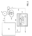
- Fig. 2 shows a schematic block diagram of an automated cardio pulmonary resuscitation apparatus according to a second aspect.
- the part of the apparatus around the chest compression actuator 102, the human chest 104, and the physiological parameter sensor is identical or similar to what is illustrated in Fig. 1 .
- the feedback control loop is now incorporated in the adaptive control 208.
- the measurements of the actual compression waveform y k reach adaptive control 208 by means of connection 107.
- An iterative learning control automatically updates the system input u k of compression k until the error signal e k (i.e.
- a desired compression waveform y d (t) is also input to adaptive control 208 and iterative learning control 220.
- the difference between the desired compression waveform y d (t) and the actual compression waveform y k is determined and yields an error e k .
- the block d / dt determines the derivative with respect to time of the error e k and passes the calculated value on to a control signal calculator 222.
- Another input for control signal calculator 220 is provided by a memory/storage 226 for previous control signals.
- control signal calculator 222 calculates a current control signal which is stored memory/storage 224 for the current control signal.
- u k (t) is the system input (drive signal) which could be force or current the k'th compression at time (t), and e k (t) is the error signal at time t.
- the factor ⁇ (gamma) is the gain of the iterative learning law. In this way the feedforward signal converges to an optimal value and the displacement converges very closely to the desired compression waveform y d (t). Note that the above equation is only used as an example; there are many more algorithms. It is important to know that the initial feedforward signal and the gain ⁇ are chosen conservatively to avoid thorax damage. A simple PID controller is included to correct for disturbances. It is possible that the disturbance controller can be different from the one illustrated in Fig. 1 .
- the desired compression waveform y d (t) does not change from one compression to the next, although it might be envisioned to modify the desired compression waveform y d (t) as a function of the overall health condition of the patient. For example, the compression frequency and/or depth could be increased to intensify the cardio-pulmonary resuscitation when the patient has passed into a critical health condition. Nevertheless, for most subsequent compressions the desired compression waveform is the same.
- the iterative learning control algorithm uses this fact, because any modification of the operating parameters of the automated cardio pulmonary resuscitation apparatus can be checked during the next compression waveform as to whether it was successful, i.e. the error e k was reduced.
- the iterative learning control algorithm depends on the control signals that were used during previous compression cycles. In fact, at least the control signal of the immediately preceding compression cycle should be available. As already pointed out above, this could be achieved a memory/storage for previous control signal(s) 226.
- the current control signal 224 is shifted to memory/storage 226 once the compression cycle for which it was valid, is over. At the same time, older control signals are deleted from memory/storage 226 as they are not needed anymore.
- the shifting operation from memory/storage 224 to memory/storage 226 is indicated by the dotted arrow in Fig. 2 .
- the actuator driver 210 in Fig. 2 is different from the actuator driver 110 of Fig. 1 .
- Actuator driver 210 might contain an amplifier, for example.
- Fig. 3 shows a flow chart for automated cardio pulmonary resuscitation according to a first aspect of this application.
- the flow chart starts with block 301.
- the operating parameters are set to save initial values.
- at least one chest compression is performed. This allows an initial determination of the visco-elastic behavior of the chest of the current patient and possibly also of other properties of the system formed by the chest compression actuator and the chest.
- the measured values of physiological parameters are collected.
- the measured values are evaluated with respect to predetermined conditions.
- an adaptive control is performed in block 306 to modify the operating parameters of the control system, e.g. of an inner loop controller. Due to the modified operating parameters, the actual system output is modified.
- Measured values are received in block 307.
- closed loop control signals are generated by controller 112 (cf. Fig. 1 ).
- Another chest compression is performed in step 309.
- branching point 310 it is determined whether the next update of operating parameters should be performed. If currently no update of the operating parameters is planned, it branches back to block 307 in order to continue with normal closed loop control based on the currently valid operating parameters. If an update of the operating parameters should be done, it arrives at a second branching point 311 within which it is determined whether the cardio pulmonary resuscitation is to be terminated (e.g. due to a corresponding user command). If the answer is yes, it ends in block 312. If the answer is no, it branches back to block 304 and thus starts over with collecting measured values of resuscitation related physiological parameters.
- Fig. 4 shows a flow chart for automated cardio pulmonary resuscitation according to a second aspect of the application.
- the flow chart starts with block 401.
- the operating parameters are set to save initial values in block 402 and in block 403 at least one chest compression is performed.
- Measured values of resuscitation related physiological parameters are collected in block 404.
- the measured values are evaluated with respect to predetermined conditions.
- An iterative learning control is performed in block 406 and a control signal is generated in block 407.
- a chest compression according to the control signal is performed.
- the current control signal is stored during block 409 in order to be available for the next iteration that is performed during the next compression cycle.
- Fig. 5 shows a control scheme for a combined feedforward (FFW) and feedback control.
- the desired compression waveform y d is input to a summing point 502 by means of connection 501. Another input for the summing point 502 is the actual compression waveform y k .
- the summing point 502 provides an error signal e on connection 503 which enters a (feedback) controller 504.
- the output of the (feedback) controller 504 is added to a feedforward control signal f k+1 provided by a feedforward controller 505 at a summing point 506.
- the sum u of feedback control signal and feedforward control signal is transmitted to the system 507 (SYS).
- the system 507 reacts with an actual compression waveform y k on connection 508 which also has a branch back to the summing point 502.
- the servo control tries to minimize the error signal, i.e. the difference between the desired compression waveform y d and the measured or actual compression waveform y k (the feedback signal).
- a feedforward (FFW) input is optional, but offers for example a better following of commanded motion.
- the gain settings that are needed should not be too low (poor following) or too high (system instability, excessive forces possible).
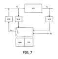
- Fig. 7 shows a servo controller for iterative learning control (ILC).
- the block SYS represents the system comprising principally the chest and the chest compression actuator. It receives the system input (drive signal) u k as input and reacts with a measured compression waveform y k . Both, the system input u k and the measured compression waveform y k are supplied to an iterative learning controller via a respective memory MEM.
- the iterative learning controller produces a system input u k+1 for the next cycle, which is stored in a further memory MEM until it is used during the next cycle.
- the two left memories MEM could also be combined, but were drawn separately for the sake of clarity.
- the iterative learning controller comprises a feedforward part FFW and a simple PID controller for correcting disturbances.
- Figures 8 to 10 show different time diagrams of the desired compression waveform y d and the actual compression waveform y k for different types of controllers.
- the desired waveform y d is always the same in order to allow a comparison.
- Fig. 8 shows the time diagram for the system output y k in the case of a PID controller with conservative gain settings.
- a gain of 5 is too low, because the desired waveform y d is not very closed replicated by the system output y k .
- the rise and fall rates are too slow and broaden each compression pulse over time so that two adjacent compression pulses are merged with each other. This might cause a problem for blood perfusion, because the heart has not enough time to relax again before the next compression.
- Fig. 10 shows a result of an automated cardio pulmonary resuscitation apparatus based on iterative learning control (ILC).
- the mechanical system i.e. the patient
- the mechanical system is the same as in the PID cases of Figures 8 and 9 .
- the desired compression curve (repeated as dotted line in the lower time diagram for better comparability) is approximated very closely within a few pulses.
- the optimum feedforward pulse is found automatically, the desired compression pulse is reached quickly and much more accurately than that achieved by the PID controller. Note that a low PID gain can be used and changes in the load are followed automatically.
- a computer program may be stored/distributed on a suitable medium, such as an optical storage medium or a solid-state medium supplied together with or as part of other hardware, but may also be distributed in other forms, such as via the Internet or other wired or wireless telecommunication systems. Any reference signs in the claims should not be construed as limiting the scope.
Landscapes
- Health & Medical Sciences (AREA)
- Cardiology (AREA)
- Heart & Thoracic Surgery (AREA)
- Emergency Medicine (AREA)
- Pulmonology (AREA)
- Epidemiology (AREA)
- Pain & Pain Management (AREA)
- Physical Education & Sports Medicine (AREA)
- Rehabilitation Therapy (AREA)
- Life Sciences & Earth Sciences (AREA)
- Animal Behavior & Ethology (AREA)
- General Health & Medical Sciences (AREA)
- Public Health (AREA)
- Veterinary Medicine (AREA)
- Percussion Or Vibration Massage (AREA)
Claims (3)
- Gerät zur automatisierten Herz-Lungen-Wiederbelebung, das Folgendes umfasst:- ein Brustkorbkompressions-Betätigungselement (102) zum Ausüben einer Kraft auf den Brustkorb eines Patienten basierend auf einem Ansteuerungssignal,- einen Sensor für physiologische Parameter (106) zum Messen von wenigstens einer Bewegung des Brustkorbs über die Zeit,- eine Betätigungselement-Ansteuerungseinheit (110; 210) zum Zuführen von zeitvariierenden Ansteuerungssignalen zu dem Brustkorbkompressions-Betätigungselement (102) in Abhängigkeit von Betriebsparametern (113, 114) der Betätigungselement-Ansteuerungseinheit (102), wobei die Betriebsparameter ein dynamisches Verhalten eines das Brustkorbkompressions-Betätigungselement (102) und den Brustkorb (104) umfassenden Systems ermitteln, wobei einer der Betriebsparameter ein gewünschtes Signalform-Zeit-Diagramm für die Brustkorbkompression (113) ist und ein weiterer Betriebsparameter eine Verstärkung einer Steuereinheit (112) ist,und wobei die Betätigungselement-Ansteuerungseinheit Folgendes umfasst:- Speicher zum Speichern der Betriebsparameter, und- die Steuereinheit (112) zum Berechnen eines Brustkorbkompressions-Signalform-Zeit-Diagramms basierend auf der gemessenen Bewegung des Brustkorbs über die Zeit,und das Gerät weiterhin Folgendes umfasst:- eine adaptive Steuerung (108; 208) zum iterativen Ermitteln eines nachfolgenden Ansteuerungssignals für das Brustkorbkompressions-Betätigungselement basierend auf einem Vergleich des Brustkorbkompressions-Signalform-Zeit-Diagramms mit dem gewünschten Signalform-Zeit-Diagramm für die Brustkorbkompression und Anpassen der gespeicherten Verstärkung, um sie mit jeder Iteration nahe an das gewünschte Signalform-Zeit-Diagramm für die Brustkorbkompression zu konvergieren.
- Gerät zur automatisierten Herz-Lungen-Wiederbelebung nach Anspruch 1, wobei der Vergleich eine Differenz zwischen dem gemessenen Brustkorbkompressions-Signalform-Zeit-Diagramm und der gewünschten Signalform ist und die Differenz in Bezug auf die Zeit differenziert.
- Gerät zur automatisierten Herz-Lungen-Wiederbelebung nach Anspruch 2, wobei die Iteration definiert ist durch ein iteratives Lerngesetz wie folgt:
 wobei uk(t) ein Steuersignal für das Brustkorbkompressions-Betätigungselement (102) während eines aktuellen Zeitintervalls ist,uk+1(t) ein Steuersignal für das Brustkorbkompressions-Betätigungselement (102) während eines nachfolgenden Zeitintervalls ist,γ eine iterative Lernverstärkung ist,ek(t) die Differenz zwischen dem gewünschten Wert und dem gemessenen Wert ist, undd/dt die Ableitung in Bezug auf die Zeit ist.
Priority Applications (1)
| Application Number | Priority Date | Filing Date | Title |
|---|---|---|---|
| EP09769733.8A EP2303218B1 (de) | 2008-06-26 | 2009-06-19 | Intelligentes servogerät für ein mechanisches cpr-system |
Applications Claiming Priority (3)
| Application Number | Priority Date | Filing Date | Title |
|---|---|---|---|
| EP08159058 | 2008-06-26 | ||
| PCT/IB2009/052631 WO2009156924A1 (en) | 2008-06-26 | 2009-06-19 | Smart servo for a mechanical cpr system |
| EP09769733.8A EP2303218B1 (de) | 2008-06-26 | 2009-06-19 | Intelligentes servogerät für ein mechanisches cpr-system |
Publications (2)
| Publication Number | Publication Date |
|---|---|
| EP2303218A1 EP2303218A1 (de) | 2011-04-06 |
| EP2303218B1 true EP2303218B1 (de) | 2015-09-30 |
Family
ID=41139295
Family Applications (1)
| Application Number | Title | Priority Date | Filing Date |
|---|---|---|---|
| EP09769733.8A Active EP2303218B1 (de) | 2008-06-26 | 2009-06-19 | Intelligentes servogerät für ein mechanisches cpr-system |
Country Status (7)
| Country | Link |
|---|---|
| US (1) | US20110166490A1 (de) |
| EP (1) | EP2303218B1 (de) |
| JP (1) | JP5449340B2 (de) |
| CN (1) | CN102076307B (de) |
| BR (1) | BRPI0910176A2 (de) |
| RU (1) | RU2504356C2 (de) |
| WO (1) | WO2009156924A1 (de) |
Cited By (1)
| Publication number | Priority date | Publication date | Assignee | Title |
|---|---|---|---|---|
| EP4514302A1 (de) * | 2022-04-25 | 2025-03-05 | Koninklijke Philips N.V. | Mechanisches system mit geschlossenem regelkreis mit physiologischem feedback |
Families Citing this family (18)
| Publication number | Priority date | Publication date | Assignee | Title |
|---|---|---|---|---|
| WO2011011633A2 (en) * | 2009-07-22 | 2011-01-27 | Atreo Medical, Inc. | Optical techniques for the measurement of chest compression depth and other parameters during cpr |
| EP2637626B1 (de) | 2010-11-11 | 2019-10-30 | Koninklijke Philips N.V. | Thoraxverfolgungsalgorithmus für ein automatisiertes cpr-gerät |
| CN102119908B (zh) * | 2011-03-21 | 2013-06-05 | 中国人民解放军军事医学科学院卫生装备研究所 | 闭环胸外按压系统 |
| US8942803B1 (en) | 2013-08-30 | 2015-01-27 | Zoll Medical Corporation | System and method for distinguishing manual from automated CPR |
| WO2015075691A1 (en) | 2013-11-25 | 2015-05-28 | Koninklijke Philips N.V. | Compact electro-mechanical chest compression drive |
| CN104224502B (zh) * | 2014-09-02 | 2016-03-16 | 青岛市市立医院 | 一种直立倾斜试验用外胸揉按装置 |
| DE112016003319T5 (de) * | 2015-07-23 | 2018-04-12 | Nonin Medical, Inc. | Überwachung und rückmeldung zur wiederbelebung |
| US10729615B2 (en) * | 2015-10-19 | 2020-08-04 | Physio-Control, Inc. | CPR chest compression system with dynamic parameters based on physiological feedback |
| US10832594B2 (en) | 2017-03-09 | 2020-11-10 | Zoll Medical Corporation | Automated detection of cardiopulmonary resuscitation chest compressions |
| US11311457B2 (en) | 2017-03-09 | 2022-04-26 | Zoll Medical Corporation | Automated detection of cardiopulmonary resuscitation chest compressions |
| CN107045286A (zh) * | 2017-04-28 | 2017-08-15 | 青岛科技大学 | 基于知识增强和重复学习的高效率自适应控制方法 |
| US11179293B2 (en) | 2017-07-28 | 2021-11-23 | Stryker Corporation | Patient support system with chest compression system and harness assembly with sensor system |
| WO2020018923A1 (en) | 2018-07-20 | 2020-01-23 | Regents Of The University Of Minnesota | Closed-loop system for cardiopulmonary resuscitation (cpr) |
| EP3735954A1 (de) * | 2019-05-06 | 2020-11-11 | Koninklijke Philips N.V. | Herz-lungen-wiederbelebungsvorrichtung, steuerungsverfahren und computerprogramm |
| US12121493B2 (en) | 2019-08-16 | 2024-10-22 | The Feinstein Institutes For Medical Research | System and method for optimization of CPR chest compressions |
| KR102489017B1 (ko) * | 2022-07-20 | 2023-01-18 | 주식회사 씨유메디칼시스템 | 환자의 흉부 압박 및 제세동을 위한 응급치료장치와 환자의 흉부 압박 깊이 소실 보정방법 |
| CN116370291B (zh) * | 2023-04-23 | 2025-09-19 | 山东大学 | 面向狭小空间的便携式胸腹部自动化按压装置及控制方法 |
| CN120694874A (zh) * | 2025-04-21 | 2025-09-26 | 苏州尚领医疗科技有限公司 | 心肺复苏机 |
Family Cites Families (13)
| Publication number | Priority date | Publication date | Assignee | Title |
|---|---|---|---|---|
| US5738637A (en) * | 1995-12-15 | 1998-04-14 | Deca-Medics, Inc. | Chest compression apparatus for cardiac arrest |
| US6463327B1 (en) * | 1998-06-11 | 2002-10-08 | Cprx Llc | Stimulatory device and methods to electrically stimulate the phrenic nerve |
| US6390996B1 (en) * | 1998-11-09 | 2002-05-21 | The Johns Hopkins University | CPR chest compression monitor |
| US7220235B2 (en) * | 2003-06-27 | 2007-05-22 | Zoll Medical Corporation | Method and apparatus for enhancement of chest compressions during CPR |
| US8939922B2 (en) * | 2005-02-15 | 2015-01-27 | Laerdal Medical As | Standalone system for assisting in a life-saving situation |
| CN2840991Y (zh) * | 2005-10-27 | 2006-11-29 | 张国强 | 全自动心肺复苏按压与监测装置 |
| US8007451B2 (en) | 2006-05-11 | 2011-08-30 | Laerdal Medical As | Servo motor for CPR with decompression stroke faster than the compression stroke |
| US7775996B2 (en) * | 2006-10-20 | 2010-08-17 | Laerdal Medical As | Chest compression system |
| EP1913922A3 (de) * | 2006-10-20 | 2008-06-25 | Laerdal Medical AS | Thoraxkompressionssystem |
| US20080146973A1 (en) * | 2006-12-15 | 2008-06-19 | Laerdal Medical As | System for providing feedback on chest compression in CPR |
| US8394040B2 (en) * | 2006-12-15 | 2013-03-12 | Laerdal Medical As | Signal processing device for providing feedback on chest compression in CPR |
| GB2449695A (en) * | 2007-05-31 | 2008-12-03 | Laerdal Medical As | Monitoring the efficacy of chest compressions |
| JP5372011B2 (ja) * | 2007-12-19 | 2013-12-18 | コーニンクレッカ フィリップス エヌ ヴェ | 自動cprに対するシステム及び方法 |
-
2009
- 2009-06-19 EP EP09769733.8A patent/EP2303218B1/de active Active
- 2009-06-19 US US12/997,897 patent/US20110166490A1/en not_active Abandoned
- 2009-06-19 BR BRPI0910176A patent/BRPI0910176A2/pt active Search and Examination
- 2009-06-19 JP JP2011515691A patent/JP5449340B2/ja active Active
- 2009-06-19 CN CN200980124239.7A patent/CN102076307B/zh active Active
- 2009-06-19 WO PCT/IB2009/052631 patent/WO2009156924A1/en not_active Ceased
- 2009-06-19 RU RU2011102759/14A patent/RU2504356C2/ru not_active IP Right Cessation
Cited By (1)
| Publication number | Priority date | Publication date | Assignee | Title |
|---|---|---|---|---|
| EP4514302A1 (de) * | 2022-04-25 | 2025-03-05 | Koninklijke Philips N.V. | Mechanisches system mit geschlossenem regelkreis mit physiologischem feedback |
Also Published As
| Publication number | Publication date |
|---|---|
| CN102076307B (zh) | 2013-12-18 |
| EP2303218A1 (de) | 2011-04-06 |
| CN102076307A (zh) | 2011-05-25 |
| WO2009156924A1 (en) | 2009-12-30 |
| JP5449340B2 (ja) | 2014-03-19 |
| JP2011525835A (ja) | 2011-09-29 |
| RU2504356C2 (ru) | 2014-01-20 |
| US20110166490A1 (en) | 2011-07-07 |
| BRPI0910176A2 (pt) | 2016-06-14 |
| RU2011102759A (ru) | 2012-08-10 |
Similar Documents
| Publication | Publication Date | Title |
|---|---|---|
| US20110166490A1 (en) | Smart Servo for a Mechanical CPR System | |
| JP5372011B2 (ja) | 自動cprに対するシステム及び方法 | |
| US20250367426A1 (en) | Systems and methods for controlling a heart pump to minimize myocardial oxygen consumption | |
| EP2314347A1 (de) | Herzstimulation bei diastolischer Dysfunktion | |
| CN107920765B (zh) | 非侵入式血压监测设备和方法 | |
| CN108136147B (zh) | 具有使用经典反馈控制的自动控制患者呼吸功的机械通气 | |
| CN116173397B (zh) | 转速控制装置和方法、心室辅助系统、存储介质及设备 | |
| JP2004227062A (ja) | リミットサイクルオートチューニング方法およびヒートクール制御装置 | |
| JP2025513473A5 (de) | ||
| US20250288487A1 (en) | Closed loop mechanical system with physiological feedback | |
| EP3687386B1 (de) | Verfahren zur verwendung in der optimierung einer nichtinvasiven blutdruckmessvorrichtung | |
| CN120251487A (zh) | 一种脉动泵系统、医疗器械植介入模拟系统及控制方法 | |
| US20240108542A1 (en) | Mechanical CPR Device with Flex Correction | |
| CN120037097B (zh) | 心肺复苏按压控制装置、计算设备和计算机可读存储介质 | |
| JPH0577416B2 (de) | ||
| CN119270963A (zh) | 生物能量共振舱的智能控制方法及装置 | |
| Wu et al. | The application of computer control in the left ventricular assist system | |
| CN121714246A (zh) | 一种多模态觉醒调控闭环生物反馈系统、方法及介质 | |
| CN116785142A (zh) | 具有振动头的机器人的控制方法、控制装置及理疗机器人 | |
| Dietmar et al. | A nonlinear circulatory model for artificial heart studies |
Legal Events
| Date | Code | Title | Description |
|---|---|---|---|
| PUAI | Public reference made under article 153(3) epc to a published international application that has entered the european phase |
Free format text: ORIGINAL CODE: 0009012 |
|
| 17P | Request for examination filed |
Effective date: 20110126 |
|
| AK | Designated contracting states |
Kind code of ref document: A1 Designated state(s): AT BE BG CH CY CZ DE DK EE ES FI FR GB GR HR HU IE IS IT LI LT LU LV MC MK MT NL NO PL PT RO SE SI SK TR |
|
| AX | Request for extension of the european patent |
Extension state: AL BA RS |
|
| DAX | Request for extension of the european patent (deleted) | ||
| RAP1 | Party data changed (applicant data changed or rights of an application transferred) |
Owner name: KONINKLIJKE PHILIPS N.V. |
|
| 17Q | First examination report despatched |
Effective date: 20131022 |
|
| GRAP | Despatch of communication of intention to grant a patent |
Free format text: ORIGINAL CODE: EPIDOSNIGR1 |
|
| INTG | Intention to grant announced |
Effective date: 20150522 |
|
| GRAS | Grant fee paid |
Free format text: ORIGINAL CODE: EPIDOSNIGR3 |
|
| GRAA | (expected) grant |
Free format text: ORIGINAL CODE: 0009210 |
|
| AK | Designated contracting states |
Kind code of ref document: B1 Designated state(s): AT BE BG CH CY CZ DE DK EE ES FI FR GB GR HR HU IE IS IT LI LT LU LV MC MK MT NL NO PL PT RO SE SI SK TR |
|
| REG | Reference to a national code |
Ref country code: CH Ref legal event code: EP Ref country code: GB Ref legal event code: FG4D |
|
| REG | Reference to a national code |
Ref country code: AT Ref legal event code: REF Ref document number: 751954 Country of ref document: AT Kind code of ref document: T Effective date: 20151015 |
|
| REG | Reference to a national code |
Ref country code: IE Ref legal event code: FG4D |
|
| REG | Reference to a national code |
Ref country code: DE Ref legal event code: R096 Ref document number: 602009033948 Country of ref document: DE |
|
| PG25 | Lapsed in a contracting state [announced via postgrant information from national office to epo] |
Ref country code: LV Free format text: LAPSE BECAUSE OF FAILURE TO SUBMIT A TRANSLATION OF THE DESCRIPTION OR TO PAY THE FEE WITHIN THE PRESCRIBED TIME-LIMIT Effective date: 20150930 Ref country code: LT Free format text: LAPSE BECAUSE OF FAILURE TO SUBMIT A TRANSLATION OF THE DESCRIPTION OR TO PAY THE FEE WITHIN THE PRESCRIBED TIME-LIMIT Effective date: 20150930 Ref country code: NO Free format text: LAPSE BECAUSE OF FAILURE TO SUBMIT A TRANSLATION OF THE DESCRIPTION OR TO PAY THE FEE WITHIN THE PRESCRIBED TIME-LIMIT Effective date: 20151230 Ref country code: GR Free format text: LAPSE BECAUSE OF FAILURE TO SUBMIT A TRANSLATION OF THE DESCRIPTION OR TO PAY THE FEE WITHIN THE PRESCRIBED TIME-LIMIT Effective date: 20151231 Ref country code: FI Free format text: LAPSE BECAUSE OF FAILURE TO SUBMIT A TRANSLATION OF THE DESCRIPTION OR TO PAY THE FEE WITHIN THE PRESCRIBED TIME-LIMIT Effective date: 20150930 |
|
| REG | Reference to a national code |
Ref country code: NL Ref legal event code: MP Effective date: 20150930 |
|
| REG | Reference to a national code |
Ref country code: LT Ref legal event code: MG4D |
|
| REG | Reference to a national code |
Ref country code: AT Ref legal event code: MK05 Ref document number: 751954 Country of ref document: AT Kind code of ref document: T Effective date: 20150930 |
|
| PG25 | Lapsed in a contracting state [announced via postgrant information from national office to epo] |
Ref country code: SE Free format text: LAPSE BECAUSE OF FAILURE TO SUBMIT A TRANSLATION OF THE DESCRIPTION OR TO PAY THE FEE WITHIN THE PRESCRIBED TIME-LIMIT Effective date: 20150930 Ref country code: HR Free format text: LAPSE BECAUSE OF FAILURE TO SUBMIT A TRANSLATION OF THE DESCRIPTION OR TO PAY THE FEE WITHIN THE PRESCRIBED TIME-LIMIT Effective date: 20150930 |
|
| PG25 | Lapsed in a contracting state [announced via postgrant information from national office to epo] |
Ref country code: IT Free format text: LAPSE BECAUSE OF FAILURE TO SUBMIT A TRANSLATION OF THE DESCRIPTION OR TO PAY THE FEE WITHIN THE PRESCRIBED TIME-LIMIT Effective date: 20150930 Ref country code: EE Free format text: LAPSE BECAUSE OF FAILURE TO SUBMIT A TRANSLATION OF THE DESCRIPTION OR TO PAY THE FEE WITHIN THE PRESCRIBED TIME-LIMIT Effective date: 20150930 Ref country code: IS Free format text: LAPSE BECAUSE OF FAILURE TO SUBMIT A TRANSLATION OF THE DESCRIPTION OR TO PAY THE FEE WITHIN THE PRESCRIBED TIME-LIMIT Effective date: 20160130 Ref country code: NL Free format text: LAPSE BECAUSE OF FAILURE TO SUBMIT A TRANSLATION OF THE DESCRIPTION OR TO PAY THE FEE WITHIN THE PRESCRIBED TIME-LIMIT Effective date: 20150930 Ref country code: CZ Free format text: LAPSE BECAUSE OF FAILURE TO SUBMIT A TRANSLATION OF THE DESCRIPTION OR TO PAY THE FEE WITHIN THE PRESCRIBED TIME-LIMIT Effective date: 20150930 Ref country code: ES Free format text: LAPSE BECAUSE OF FAILURE TO SUBMIT A TRANSLATION OF THE DESCRIPTION OR TO PAY THE FEE WITHIN THE PRESCRIBED TIME-LIMIT Effective date: 20150930 Ref country code: SK Free format text: LAPSE BECAUSE OF FAILURE TO SUBMIT A TRANSLATION OF THE DESCRIPTION OR TO PAY THE FEE WITHIN THE PRESCRIBED TIME-LIMIT Effective date: 20150930 |
|
| PG25 | Lapsed in a contracting state [announced via postgrant information from national office to epo] |
Ref country code: PL Free format text: LAPSE BECAUSE OF FAILURE TO SUBMIT A TRANSLATION OF THE DESCRIPTION OR TO PAY THE FEE WITHIN THE PRESCRIBED TIME-LIMIT Effective date: 20150930 Ref country code: RO Free format text: LAPSE BECAUSE OF FAILURE TO SUBMIT A TRANSLATION OF THE DESCRIPTION OR TO PAY THE FEE WITHIN THE PRESCRIBED TIME-LIMIT Effective date: 20150930 Ref country code: PT Free format text: LAPSE BECAUSE OF FAILURE TO SUBMIT A TRANSLATION OF THE DESCRIPTION OR TO PAY THE FEE WITHIN THE PRESCRIBED TIME-LIMIT Effective date: 20160201 Ref country code: AT Free format text: LAPSE BECAUSE OF FAILURE TO SUBMIT A TRANSLATION OF THE DESCRIPTION OR TO PAY THE FEE WITHIN THE PRESCRIBED TIME-LIMIT Effective date: 20150930 |
|
| REG | Reference to a national code |
Ref country code: FR Ref legal event code: PLFP Year of fee payment: 8 |
|
| REG | Reference to a national code |
Ref country code: DE Ref legal event code: R097 Ref document number: 602009033948 Country of ref document: DE |
|
| PLBE | No opposition filed within time limit |
Free format text: ORIGINAL CODE: 0009261 |
|
| STAA | Information on the status of an ep patent application or granted ep patent |
Free format text: STATUS: NO OPPOSITION FILED WITHIN TIME LIMIT |
|
| PG25 | Lapsed in a contracting state [announced via postgrant information from national office to epo] |
Ref country code: DK Free format text: LAPSE BECAUSE OF FAILURE TO SUBMIT A TRANSLATION OF THE DESCRIPTION OR TO PAY THE FEE WITHIN THE PRESCRIBED TIME-LIMIT Effective date: 20150930 |
|
| 26N | No opposition filed |
Effective date: 20160701 |
|
| PG25 | Lapsed in a contracting state [announced via postgrant information from national office to epo] |
Ref country code: SI Free format text: LAPSE BECAUSE OF FAILURE TO SUBMIT A TRANSLATION OF THE DESCRIPTION OR TO PAY THE FEE WITHIN THE PRESCRIBED TIME-LIMIT Effective date: 20150930 |
|
| PG25 | Lapsed in a contracting state [announced via postgrant information from national office to epo] |
Ref country code: BE Free format text: LAPSE BECAUSE OF FAILURE TO SUBMIT A TRANSLATION OF THE DESCRIPTION OR TO PAY THE FEE WITHIN THE PRESCRIBED TIME-LIMIT Effective date: 20150930 |
|
| PG25 | Lapsed in a contracting state [announced via postgrant information from national office to epo] |
Ref country code: MC Free format text: LAPSE BECAUSE OF FAILURE TO SUBMIT A TRANSLATION OF THE DESCRIPTION OR TO PAY THE FEE WITHIN THE PRESCRIBED TIME-LIMIT Effective date: 20150930 |
|
| REG | Reference to a national code |
Ref country code: CH Ref legal event code: PL |
|
| REG | Reference to a national code |
Ref country code: IE Ref legal event code: MM4A |
|
| PG25 | Lapsed in a contracting state [announced via postgrant information from national office to epo] |
Ref country code: LI Free format text: LAPSE BECAUSE OF NON-PAYMENT OF DUE FEES Effective date: 20160630 Ref country code: CH Free format text: LAPSE BECAUSE OF NON-PAYMENT OF DUE FEES Effective date: 20160630 |
|
| PG25 | Lapsed in a contracting state [announced via postgrant information from national office to epo] |
Ref country code: IE Free format text: LAPSE BECAUSE OF NON-PAYMENT OF DUE FEES Effective date: 20160619 |
|
| REG | Reference to a national code |
Ref country code: FR Ref legal event code: PLFP Year of fee payment: 9 |
|
| PG25 | Lapsed in a contracting state [announced via postgrant information from national office to epo] |
Ref country code: HU Free format text: LAPSE BECAUSE OF FAILURE TO SUBMIT A TRANSLATION OF THE DESCRIPTION OR TO PAY THE FEE WITHIN THE PRESCRIBED TIME-LIMIT; INVALID AB INITIO Effective date: 20090619 Ref country code: CY Free format text: LAPSE BECAUSE OF FAILURE TO SUBMIT A TRANSLATION OF THE DESCRIPTION OR TO PAY THE FEE WITHIN THE PRESCRIBED TIME-LIMIT Effective date: 20150930 |
|
| PG25 | Lapsed in a contracting state [announced via postgrant information from national office to epo] |
Ref country code: TR Free format text: LAPSE BECAUSE OF FAILURE TO SUBMIT A TRANSLATION OF THE DESCRIPTION OR TO PAY THE FEE WITHIN THE PRESCRIBED TIME-LIMIT Effective date: 20150930 Ref country code: MK Free format text: LAPSE BECAUSE OF FAILURE TO SUBMIT A TRANSLATION OF THE DESCRIPTION OR TO PAY THE FEE WITHIN THE PRESCRIBED TIME-LIMIT Effective date: 20150930 Ref country code: MT Free format text: LAPSE BECAUSE OF NON-PAYMENT OF DUE FEES Effective date: 20160630 Ref country code: LU Free format text: LAPSE BECAUSE OF NON-PAYMENT OF DUE FEES Effective date: 20160619 |
|
| REG | Reference to a national code |
Ref country code: FR Ref legal event code: PLFP Year of fee payment: 10 |
|
| PG25 | Lapsed in a contracting state [announced via postgrant information from national office to epo] |
Ref country code: BG Free format text: LAPSE BECAUSE OF FAILURE TO SUBMIT A TRANSLATION OF THE DESCRIPTION OR TO PAY THE FEE WITHIN THE PRESCRIBED TIME-LIMIT Effective date: 20150930 |
|
| PGFP | Annual fee paid to national office [announced via postgrant information from national office to epo] |
Ref country code: FR Payment date: 20200626 Year of fee payment: 12 |
|
| PG25 | Lapsed in a contracting state [announced via postgrant information from national office to epo] |
Ref country code: FR Free format text: LAPSE BECAUSE OF NON-PAYMENT OF DUE FEES Effective date: 20210630 |
|
| REG | Reference to a national code |
Ref country code: DE Ref legal event code: R084 Ref document number: 602009033948 Country of ref document: DE |
|
| REG | Reference to a national code |
Ref country code: GB Ref legal event code: 746 Effective date: 20240718 |
|
| PGFP | Annual fee paid to national office [announced via postgrant information from national office to epo] |
Ref country code: DE Payment date: 20250626 Year of fee payment: 17 |
|
| PGFP | Annual fee paid to national office [announced via postgrant information from national office to epo] |
Ref country code: GB Payment date: 20260601 Year of fee payment: 18 |