EP2302342A1 - Infrarotthermometer - Google Patents
Infrarotthermometer Download PDFInfo
- Publication number
- EP2302342A1 EP2302342A1 EP20090170437 EP09170437A EP2302342A1 EP 2302342 A1 EP2302342 A1 EP 2302342A1 EP 20090170437 EP20090170437 EP 20090170437 EP 09170437 A EP09170437 A EP 09170437A EP 2302342 A1 EP2302342 A1 EP 2302342A1
- Authority
- EP
- European Patent Office
- Prior art keywords
- infrared thermometer
- infrared
- thermometer
- spot
- temperature
- Prior art date
- Legal status (The legal status is an assumption and is not a legal conclusion. Google has not performed a legal analysis and makes no representation as to the accuracy of the status listed.)
- Withdrawn
Links
- 241001465754 Metazoa Species 0.000 claims abstract description 10
- 238000000034 method Methods 0.000 claims abstract description 10
- 238000005259 measurement Methods 0.000 claims description 26
- 210000003128 head Anatomy 0.000 claims description 22
- 210000001061 forehead Anatomy 0.000 claims description 21
- 238000004422 calculation algorithm Methods 0.000 claims description 17
- 210000000613 ear canal Anatomy 0.000 claims description 14
- 230000003287 optical effect Effects 0.000 claims description 7
- 210000000664 rectum Anatomy 0.000 claims description 4
- 238000001514 detection method Methods 0.000 claims description 2
- 238000009529 body temperature measurement Methods 0.000 description 8
- 239000000523 sample Substances 0.000 description 6
- 230000036757 core body temperature Effects 0.000 description 4
- 238000003780 insertion Methods 0.000 description 4
- 230000037431 insertion Effects 0.000 description 4
- 210000000214 mouth Anatomy 0.000 description 4
- 238000004364 calculation method Methods 0.000 description 3
- 230000036760 body temperature Effects 0.000 description 2
- 230000001419 dependent effect Effects 0.000 description 2
- 239000004033 plastic Substances 0.000 description 2
- 230000005855 radiation Effects 0.000 description 2
- 241000282412 Homo Species 0.000 description 1
- 241000282320 Panthera leo Species 0.000 description 1
- 239000003990 capacitor Substances 0.000 description 1
- 210000000959 ear middle Anatomy 0.000 description 1
- 230000007613 environmental effect Effects 0.000 description 1
- 230000006870 function Effects 0.000 description 1
- 238000004519 manufacturing process Methods 0.000 description 1
- 230000000116 mitigating effect Effects 0.000 description 1
- 238000000053 physical method Methods 0.000 description 1
- 125000006850 spacer group Chemical group 0.000 description 1
- 210000003454 tympanic membrane Anatomy 0.000 description 1
Images


Classifications
-
- G—PHYSICS
- G01—MEASURING; TESTING
- G01J—MEASUREMENT OF INTENSITY, VELOCITY, SPECTRAL CONTENT, POLARISATION, PHASE OR PULSE CHARACTERISTICS OF INFRARED, VISIBLE OR ULTRAVIOLET LIGHT; COLORIMETRY; RADIATION PYROMETRY
- G01J5/00—Radiation pyrometry, e.g. infrared or optical thermometry
- G01J5/02—Constructional details
-
- G—PHYSICS
- G01—MEASURING; TESTING
- G01J—MEASUREMENT OF INTENSITY, VELOCITY, SPECTRAL CONTENT, POLARISATION, PHASE OR PULSE CHARACTERISTICS OF INFRARED, VISIBLE OR ULTRAVIOLET LIGHT; COLORIMETRY; RADIATION PYROMETRY
- G01J5/00—Radiation pyrometry, e.g. infrared or optical thermometry
- G01J5/0022—Radiation pyrometry, e.g. infrared or optical thermometry for sensing the radiation of moving bodies
- G01J5/0025—Living bodies
-
- G—PHYSICS
- G01—MEASURING; TESTING
- G01J—MEASUREMENT OF INTENSITY, VELOCITY, SPECTRAL CONTENT, POLARISATION, PHASE OR PULSE CHARACTERISTICS OF INFRARED, VISIBLE OR ULTRAVIOLET LIGHT; COLORIMETRY; RADIATION PYROMETRY
- G01J5/00—Radiation pyrometry, e.g. infrared or optical thermometry
- G01J5/02—Constructional details
- G01J5/026—Control of working procedures of a pyrometer, other than calibration; Bandwidth calculation; Gain control
-
- G—PHYSICS
- G01—MEASURING; TESTING
- G01J—MEASUREMENT OF INTENSITY, VELOCITY, SPECTRAL CONTENT, POLARISATION, PHASE OR PULSE CHARACTERISTICS OF INFRARED, VISIBLE OR ULTRAVIOLET LIGHT; COLORIMETRY; RADIATION PYROMETRY
- G01J5/00—Radiation pyrometry, e.g. infrared or optical thermometry
- G01J5/02—Constructional details
- G01J5/0275—Control or determination of height or distance or angle information for sensors or receivers
-
- G—PHYSICS
- G01—MEASURING; TESTING
- G01J—MEASUREMENT OF INTENSITY, VELOCITY, SPECTRAL CONTENT, POLARISATION, PHASE OR PULSE CHARACTERISTICS OF INFRARED, VISIBLE OR ULTRAVIOLET LIGHT; COLORIMETRY; RADIATION PYROMETRY
- G01J5/00—Radiation pyrometry, e.g. infrared or optical thermometry
- G01J5/02—Constructional details
- G01J5/04—Casings
- G01J5/049—Casings for tympanic thermometers
-
- G—PHYSICS
- G01—MEASURING; TESTING
- G01J—MEASUREMENT OF INTENSITY, VELOCITY, SPECTRAL CONTENT, POLARISATION, PHASE OR PULSE CHARACTERISTICS OF INFRARED, VISIBLE OR ULTRAVIOLET LIGHT; COLORIMETRY; RADIATION PYROMETRY
- G01J5/00—Radiation pyrometry, e.g. infrared or optical thermometry
- G01J5/02—Constructional details
- G01J5/08—Optical arrangements
- G01J5/0846—Optical arrangements having multiple detectors for performing different types of detection, e.g. using radiometry and reflectometry channels
Definitions
- the present invention relates to infrared thermometers with infrared sensors and adapted for measuring the temperature on at least one predetermined spot on or in a human or animal body and to a method of operating an infrared thermometer.
- Temperature of humans or animals can be taken at different spots on the body, for example the mouth, the rectum, armpit or the eardrum, more precisely the external auditory canal. More recently, methods have been developed that allow for accurate measurement of temperature on the skin with infrared thermometers, more particularly on the forehead or the temples. This has been proven advantageous and uncomplicated in use, especially in regard to infant care.
- Infrared thermometers are basically non-contact thermometers that are equipped to guide infrared energy on to a detector, which converts the energy to an electrical signal that can be displayed in units of temperature after being compensated for ambient temperature variation.
- Devices for performing a temperature measurement are available for the medical professional and home use.
- One example for such a device is described in DE19929503 A1 .
- This document describes a device that can be used in a plurality of locations by using different detector heads depending on the measurement location.
- the document provides a detector head suitable for use in the ear and a detector head for application on the patient's forehead or temples.
- the application of the correct cap ensures that the temperature calculation from the measurement is performed correctly, i.e. that the right algorithm is chosen depending on the location.
- thermometer It is a drawback of this thermometer that the measuring head may be lost or that it may be difficult for inexperienced users to place the head.
- EP1271119 A1 provides a method for mitigating the risk of handling errors in performing the measurement.
- the document shows an infrared clinical ear thermometer that has means for detecting an insertion condition of the probe into the external ear canal. Measurement is permitted, once said means determine that the probe is sufficiently inserted.
- the means for determining sufficient insertions rely on first preliminary temperature measurements.
- thermometer It is an object of the present invention, to solve the problems of the prior art. It is particularly an object to provide a reliable, easy to manufacture, infrared thermometer which can perform accurate temperature measurements on various locations and which can be easily and reliably used by all users. This object is solved with an infrared thermometer according to the independent claims.
- the infrared thermometer is adapted for determining a temperature on at least one predetermined spot on or in a human or animal body and further comprises recognition means for recognizing if the sensor is properly positioned on said at least one predetermined spot.
- the infrared thermometer includes a detector, e.g. a thermopile, which converts the energy to an electrical signal that can be displayed in units of temperature after being compensated for ambient temperature variation.
- the infrared thermometer is further equipped with a microprocessor for performing calculations and/or for controlling the various functions of the infrared thermometer and with a memory for storing either algorithms relating to a temperature measurement on any one of the predetermined spots, or measurement data.
- the infrared thermometer is adapted to recognize proper position at a plurality of different predetermined spots.
- Predetermined spots according to the invention can be any spots where temperature can successfully be taken, preferably such spots where temperature is frequently and reliably taken.
- the infrared thermometer can be adapted for determining a temperature on, for example, the forehead, in the external auditory canal, the armpit, the oral cavity and/or the rectum.
- adapted for determining the temperature means that the device is able to measure an actual temperature over a certain time interval which results in a temperature curve and calculate with said temperature curve a body temperature.
- the externally measured temperature should be calculated to core body temperature, which is the effective operating temperature of a human or animal.
- a recognition means is to be understood as a means for determining on the basis of a physical measurement if the thermometer is being applied on a predetermined spot.
- an infrared thermometer is brought into proper position with a spot when sufficiently close to a spot to enable measurement.
- the thermometer can be rested or moved along on the surface of the skin while measuring.
- the thermometer can be further equipped with spacers, lashes or a rubber pad, for example to ensure adequate positioning.
- the thermometer needs to be inserted in the canal in sufficient depth.
- the thermometer can be further equipped for facilitating such an insertion by providing a narrow tip, or an essentially cone shape tip in the form of a, in particular detachable, head, thus providing for exactly the just insertion depth without the user risking injuring by probing it too deeply.
- the infrared thermometer comprises at least one additional sensor in addition to the infrared sensor for recognizing if the infrared thermometer is properly positioned on said spot.
- the infrared thermometer comprises means for selecting from at least two modes of operation, each mode of operation comprising an algorithm and corresponding to one predetermined spot. The selection is done on the basis of the recognition of the spot.
- At least one of the predetermined spot is chosen from the group consisting of the ear, in particular the external auditory canal, the head, in particular the forehead or temples, the armpit, a bodily orifice, in particular the mouth (oral cavity) or the rectum.
- the recognition means is an optical detection means, in particular an optical sensor capable of measuring light.
- the optical sensor should preferably be able to distinguish between a light and dark environment and convert this information into an electrical signal.
- photore-sistors could be used.
- photodiodes could be used.
- An infrared thermometer thus equipped can distinguish between particular predetermined spots on or in a human or animal body, for example distinguish between being placed in the external auditory canal (less light detected by optical sensor) and the forehead (more light detected by optical sensor).
- the threshold (light/dark) can be set depending on the predetermined spots in question.
- the recognition means is a capacitive sensor.
- a capacitive sensor works by measuring changes in an electrical property called capacitance. Capacitance describes how two conductive objects with a space between them respond to voltage differences. Such sensors use an alternating voltage to move the electrical charges in the target objects, thereby creating an alternating current which again is detected by the sensor. This capacitance is dependent on the proximity and the area of the object thus analysed. With that information, the infrared thermometer can be programmed to distinguish the capacitance of predetermined spots on the body, thereby recognizing if the infrared sensor is properly positioned on one of predetermined spots.
- the infrared thermometer can perform a specific operation.
- the infrared thermometer has means for selecting from a set of preinstalled algorithms the appropriate algorithm for the specific spot for calculating and displaying a temperature or temperature profile of the body temperature. Depending on the spot on which the temperature is taken, an appropriate is selected.
- the recognising of the proper position on the spot triggers the measurement process.
- Such an infrared thermometer would work automatically upon being placed on a predetermined spot. The spot will be recognised and the correct measurement routine initiated.
- thermometer may comprise a measuring adapter, said adapter being adapted for use in on at least one predetermined spot.
- Such adapters can be, for example, a cap, a detachable head or a probe.
- the adapter is most conveniently designed such as to facilitate the bringing into contact for measurement purposes with the respective predetermined spot.
- a rubber pad can be used for instance for placing the thermometer on the forehead or temples, whereas an essentially cone like shape can be used for measurement on the ear, in particular the external auditory canal.
- Such adapters are already known in the art and are readily available.
- the infrared thermometer is designed to operate in a plurality of predetermined modes of operation, each of the predetermined modes of operation corresponding to at least one predetermined spot on or in a human or animal body.
- the infrared thermometer might come equipped with algorithms to adapt the measurement profile on whether oral temperature, axial temperature or rectal temperature is taken for example.
- the infrared thermometer is equipped with at least two modes of operation, one for measurements on the head, preferably the forehead or temples, and one for measurements in the external auditory canal. Each mode of operation uses a measurement protocol, a calculation algorithm and a display and/or notification protocol.
- the recognition means is dependent on temperature measurements by the infrared thermometer.
- the recognition means may be designed to determine a temperature gradient initially measured by the thermometer and to recognize if the gradient corresponds to the gradient attributed to a specific spot.
- the infrared thermometer When moved into place at a predetermined spot, the infrared thermometer measures the actual temperature several times over a time interval. The infrared thermometer then determines a profile or gradient of the individual measurements in relation to one another. By comparing the measured profile or gradient with reference data, the infrared thermometer recognizes the spot and may begin with a respective mode of operation.
- One aspect of the present invention is a method of operating an infrared thermometer.
- the infrared thermometer is placed on or in a predetermined spot on or in a human or animal body.
- the infrared thermometer recognizes if moved into place at a predetermined spot.
- the infrared measures the temperature on the predetermined spot, and the results are displayed in readable form.
- the infrared thermometer automatically recognizes if moved into place at the predetermined spot and applies a corresponding algorithm.
- the infrared thermometer starts measuring the temperature upon recognizing the predetermined spot.
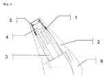
- An exemplary embodiment of the present invention is shown schematically in profile in Fig. 1 .
- An infrared thermometer head includes a plastic probe head 2 encasing an inner structure.
- the inner structure comprises an infrared sensor and a recognition means for recognizing if the sensor is properly positioned.
- the infrared sensor is made up by a thermopile sensor 4.
- the thermopile sensor 4 is held in place by a thermopile sensor holder 5.
- An infrared radiation permeable layer of the thermopile sensor holder 5 protects the thermopile sensor 4 from dirt.
- the thermopile sensor holder 5 is further surrounded ring wise by a coil 1, of a capacitive sensor.
- the capacitive sensor consists of a probe in the form of the coil 1 and a driver (not shown).
- a heat sink 3 serves at dissipating heat from the thermopile and thus minimizing environmental influence on the measurement.
- the infrared thermometer head rests on a thermometer housing 6. Electrical conduits lead from the thermometer head to the internal (not shown) of the thermometer housing 6.
- thermometer head is placed either on the forehead or introduced into the external auditory canal. Presence in the external auditory canal can be detected by the capacitive sensor through the coil 1.
- Differences or peculiarities in capacitance of the skin of the forehead in relation to the external ear canal can be stored in a device memory. Once the capacitive sensor measures a capacitance, a microprocessor compares said capacitance to a bandwidth of values characteristic for said area.
- Capacitive sensors which can be adapted and used in conjunction with the present inventions are supplied by Lion Precision (563 Shoreview Park Road, St. Paul, MN 55126).
- thermopile 4 Infrared radiation from either the tympanum or the forehead is translated into an electrical signal by the thermopile 4.
- a microprocessor in the housing translates the measured values automatically into a core body temperature and displays said value on a thermometer display (not shown).
- thermometer Apart from the positioning of the thermometer, all these steps are performed automatically.
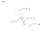
- Fig.2 is an exploded isometric schematic view of a thermometer head according to this particular embodiment.
- the plastic probe head 2 (optionally detachable) is removed, thus revealing the inner structure.
- the coil 1 is a ring like structure on top of the heat sink 3.
- the thermopile sensor holder 5 and the thermopile sensor 4 are not shown in Fig.2 .
- the mode of operation of the first exemplary embodiment according to Figures 1 and 2 is illustrated in Fig.5 .
- the infrared thermometer is adapted to perform two different algorithms, each algorithm corresponding to either one of two predetermined spots where the thermometer can be positioned for taking the temperature. If the thermometer is placed in the ear, the capacitor sensor recognizes the spot and a first algorithm is initiated. The first algorithm is designed such as to enable calculating the core body temperature based on measurement in the external auditory canal of the ear. If instead the capacitive sensor does not detect being in the ear, then, by consequence, the thermometer must have been placed on the forehead. In this instance, a second algorithm is initiated. The second algorithm is designed such as to enable determining the core body temperature based on measurements on the forehead of the patient.
- FIG. 3 A further exemplary embodiment of the present invention is shown schematically in section in Fig. 3 .
- Shown is the head of an infrared thermometer adapted to be used on the forehead.
- the infrared thermometer head rests on a thermometer housing 6, which stores a microprocessor and a display.
- the head consists of stiff annular thermopile sensor holder 5 surrounding the inner structure and which is of an essentially isosceles trapezoid like shape with rounded edges.
- a rubber pad 7 is fitted onto the thermopile sensor holder 5 and is intended for contact with the forehead, where the temperature is measured.
- the rubber pad 7 ensures a good and neat fit on the forehead.
- the coil 1 measures variations of capacitance thus detecting and recognizing being placed on the forehead.
- the infrared thermometer then begins a temperature measurement.
- the inner structure further comprises the thermopile sensor 4 and the insulating heat sink 3.
- thermometer The measurement signals from the coil 1 and the thermopile are utilized by the microprocessor in the housing 6.
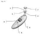
- Fig.4 a complete infrared thermometer according to the present exemplary embodiment is shown in isometric view.
- the thermometer features an on/off button 8 and a graphical display 9 for displaying the temperature taken as well as optionally any kind of error message or operation instruction.
- the thermometer head consists of a rubber pad 7 and a coil 1 between said rubber pad 7 and the thermopile sensor holder 5.
- the inside of the thermopile sensor holder 5 is filled by the thermopile sensor 4.
- the mode of operation of the second exemplary embodiment is illustrated as a flowchart in Fig.6 .
- the infrared thermometer is adapted to automatically start a measurement routine as soon as it is positioned on the forehead.
- the infrared thermometer recognises by means of the capacitive sensor whether the right position on the forehead has been taken. If that is found positive, the measurement routine is initiated. If it is found negative, the thermometer stays in stand by mode.
Landscapes
- Physics & Mathematics (AREA)
- General Physics & Mathematics (AREA)
- Spectroscopy & Molecular Physics (AREA)
- Measuring And Recording Apparatus For Diagnosis (AREA)
Priority Applications (8)
| Application Number | Priority Date | Filing Date | Title |
|---|---|---|---|
| EP20090170437 EP2302342A1 (de) | 2009-09-16 | 2009-09-16 | Infrarotthermometer |
| EP18169273.2A EP3388800B1 (de) | 2009-09-16 | 2010-09-07 | Infrarotthermometer |
| ES10749868T ES2739390T3 (es) | 2009-09-16 | 2010-09-07 | Termómetro infrarrojo |
| CN201410095301.7A CN103815882B (zh) | 2009-09-16 | 2010-09-07 | 红外线温度计 |
| PCT/EP2010/063106 WO2011032864A1 (en) | 2009-09-16 | 2010-09-07 | Infrared thermometer |
| EP10749868.5A EP2478344B1 (de) | 2009-09-16 | 2010-09-07 | Infrarotthermometer |
| CN201080041110.2A CN102597723B (zh) | 2009-09-16 | 2010-09-07 | 红外线温度计 |
| US13/496,128 US9109946B2 (en) | 2009-09-16 | 2010-09-07 | Infrared thermometer |
Applications Claiming Priority (1)
| Application Number | Priority Date | Filing Date | Title |
|---|---|---|---|
| EP20090170437 EP2302342A1 (de) | 2009-09-16 | 2009-09-16 | Infrarotthermometer |
Publications (1)
| Publication Number | Publication Date |
|---|---|
| EP2302342A1 true EP2302342A1 (de) | 2011-03-30 |
Family
ID=41226847
Family Applications (3)
| Application Number | Title | Priority Date | Filing Date |
|---|---|---|---|
| EP20090170437 Withdrawn EP2302342A1 (de) | 2009-09-16 | 2009-09-16 | Infrarotthermometer |
| EP18169273.2A Active EP3388800B1 (de) | 2009-09-16 | 2010-09-07 | Infrarotthermometer |
| EP10749868.5A Active EP2478344B1 (de) | 2009-09-16 | 2010-09-07 | Infrarotthermometer |
Family Applications After (2)
| Application Number | Title | Priority Date | Filing Date |
|---|---|---|---|
| EP18169273.2A Active EP3388800B1 (de) | 2009-09-16 | 2010-09-07 | Infrarotthermometer |
| EP10749868.5A Active EP2478344B1 (de) | 2009-09-16 | 2010-09-07 | Infrarotthermometer |
Country Status (5)
| Country | Link |
|---|---|
| US (1) | US9109946B2 (de) |
| EP (3) | EP2302342A1 (de) |
| CN (2) | CN103815882B (de) |
| ES (1) | ES2739390T3 (de) |
| WO (1) | WO2011032864A1 (de) |
Cited By (4)
| Publication number | Priority date | Publication date | Assignee | Title |
|---|---|---|---|---|
| US8657758B2 (en) | 2010-12-02 | 2014-02-25 | Welch Allyn, Inc. | Devices and methods for temperature determination |
| US20140140368A1 (en) * | 2012-11-19 | 2014-05-22 | Kaz Usa, Inc. | Non-contacxt medical thermometer with distance sensing and compensation |
| TWI492736B (zh) * | 2011-04-07 | 2015-07-21 | Bio Echo Net Inc | Infrared thermometer |
| US9448117B2 (en) | 2013-08-08 | 2016-09-20 | Bio Echo Net Inc | Infrared thermometer |
Families Citing this family (8)
| Publication number | Priority date | Publication date | Assignee | Title |
|---|---|---|---|---|
| US9261407B2 (en) * | 2009-11-02 | 2016-02-16 | Eric M. Lawson | Thermometer for determining the temperature of an animal's ear drum and method of using the same |
| US10624583B2 (en) * | 2012-11-09 | 2020-04-21 | Nonin Medical, Inc. | Reactance sensing for improved sensor placement |
| CN104374476A (zh) * | 2013-08-13 | 2015-02-25 | 联想移动通信科技有限公司 | 一种环境温度检测的方法、装置和终端 |
| WO2015072006A1 (ja) * | 2013-11-15 | 2015-05-21 | 富士通株式会社 | 赤外線検知装置 |
| CN106214132B (zh) * | 2016-07-08 | 2020-09-01 | 深圳市爱立康医疗股份有限公司 | 一种红外线温度计以及腋下测温方法 |
| CN107157451A (zh) * | 2017-03-31 | 2017-09-15 | 西藏喜年通讯科技有限公司 | 一种耳机及便携式终端 |
| CN107595246A (zh) * | 2017-08-16 | 2018-01-19 | 深圳市沃特沃德股份有限公司 | 测量生理参数的方法、装置和宠物牵引器 |
| TWI632356B (zh) * | 2017-09-29 | 2018-08-11 | 百略醫學科技股份有限公司 | 雙模式紅外線溫度量測裝置 |
Citations (8)
| Publication number | Priority date | Publication date | Assignee | Title |
|---|---|---|---|---|
| JPH095167A (ja) * | 1995-06-17 | 1997-01-10 | Nissho Corp | 鼓膜体温計 |
| DE19827343A1 (de) * | 1998-06-19 | 1999-12-23 | Braun Gmbh | Gerät zur Durchführung von Messungen im Ohr |
| DE19929503A1 (de) | 1999-06-28 | 2001-01-04 | Braun Gmbh | IR-Thermometer für unterschiedliche Meßorte |
| EP1162439A2 (de) * | 2000-06-09 | 2001-12-12 | Omron Corporation | Klinisches Strahlungsthermometer und Verfahren zur Messung der Körpertemperatur mit diesem Thermometer |
| EP1271119A1 (de) | 2001-06-19 | 2003-01-02 | Omron Corporation | Infrarot-Klinikthermometer |
| US20030099277A1 (en) * | 1998-01-30 | 2003-05-29 | Francesco Bellifemine | Infrared thermometer |
| DE202004003021U1 (de) * | 2004-02-27 | 2004-05-13 | Braun Gmbh | Infrarot-Ohrthermometer |
| US20070291820A1 (en) * | 2006-06-16 | 2007-12-20 | Gavin Yang | Infrared clinical thermometer |
Family Cites Families (15)
| Publication number | Priority date | Publication date | Assignee | Title |
|---|---|---|---|---|
| CN1168623A (zh) * | 1994-02-28 | 1997-12-24 | 伊康诺梅逊公司 | 红外鼓膜温度计 |
| US6090050A (en) * | 1998-07-16 | 2000-07-18 | Salix Medical, Inc. | Thermometric apparatus and method |
| IL126224A0 (en) * | 1998-09-15 | 1999-05-09 | Gerlitz Jonathan | Ear thermometer and detector therefor |
| US7378975B1 (en) * | 2000-06-09 | 2008-05-27 | Bed-Check Corporation | Method and apparatus for mitigating the risk of pressure sores |
| US7036978B2 (en) * | 2000-06-13 | 2006-05-02 | Omron Corporation | Pyrometer |
| EP1239271A1 (de) * | 2001-03-07 | 2002-09-11 | Microlife Intellectual Property GmbH | Medizinisches Infrarot-Thermometer |
| US7048756B2 (en) * | 2002-01-18 | 2006-05-23 | Apasara Medical Corporation | System, method and apparatus for evaluating tissue temperature |
| US6896675B2 (en) * | 2002-03-05 | 2005-05-24 | Baylis Medical Company Inc. | Intradiscal lesioning device |
| US7785266B2 (en) * | 2003-08-19 | 2010-08-31 | Advanced Monitors Corporation | Medical thermometer for determining body core temperature |
| CN2759381Y (zh) * | 2004-12-10 | 2006-02-22 | 豪展医疗科技股份有限公司 | 改良的耳温枪 |
| JP4751174B2 (ja) * | 2005-10-21 | 2011-08-17 | 株式会社バイオエコーネット | 耳式体温計 |
| US7314310B2 (en) * | 2006-04-13 | 2008-01-01 | The General Electric Company | Predictive temperature probe with proximity sensor |
| US20070248141A1 (en) * | 2006-04-21 | 2007-10-25 | Sherwood Services Ag | Infrared thermometer and probe cover thereof |
| US7810992B2 (en) * | 2007-04-09 | 2010-10-12 | Avita Corporation | Non-contact temperature-measuring device and the method thereof |
| US8306774B2 (en) * | 2009-11-02 | 2012-11-06 | Quinn David E | Thermometer for determining the temperature of an animal's ear drum and method of using same |
-
2009
- 2009-09-16 EP EP20090170437 patent/EP2302342A1/de not_active Withdrawn
-
2010
- 2010-09-07 CN CN201410095301.7A patent/CN103815882B/zh active Active
- 2010-09-07 CN CN201080041110.2A patent/CN102597723B/zh not_active Expired - Fee Related
- 2010-09-07 US US13/496,128 patent/US9109946B2/en active Active
- 2010-09-07 EP EP18169273.2A patent/EP3388800B1/de active Active
- 2010-09-07 EP EP10749868.5A patent/EP2478344B1/de active Active
- 2010-09-07 ES ES10749868T patent/ES2739390T3/es active Active
- 2010-09-07 WO PCT/EP2010/063106 patent/WO2011032864A1/en active Application Filing
Patent Citations (8)
| Publication number | Priority date | Publication date | Assignee | Title |
|---|---|---|---|---|
| JPH095167A (ja) * | 1995-06-17 | 1997-01-10 | Nissho Corp | 鼓膜体温計 |
| US20030099277A1 (en) * | 1998-01-30 | 2003-05-29 | Francesco Bellifemine | Infrared thermometer |
| DE19827343A1 (de) * | 1998-06-19 | 1999-12-23 | Braun Gmbh | Gerät zur Durchführung von Messungen im Ohr |
| DE19929503A1 (de) | 1999-06-28 | 2001-01-04 | Braun Gmbh | IR-Thermometer für unterschiedliche Meßorte |
| EP1162439A2 (de) * | 2000-06-09 | 2001-12-12 | Omron Corporation | Klinisches Strahlungsthermometer und Verfahren zur Messung der Körpertemperatur mit diesem Thermometer |
| EP1271119A1 (de) | 2001-06-19 | 2003-01-02 | Omron Corporation | Infrarot-Klinikthermometer |
| DE202004003021U1 (de) * | 2004-02-27 | 2004-05-13 | Braun Gmbh | Infrarot-Ohrthermometer |
| US20070291820A1 (en) * | 2006-06-16 | 2007-12-20 | Gavin Yang | Infrared clinical thermometer |
Cited By (9)
| Publication number | Priority date | Publication date | Assignee | Title |
|---|---|---|---|---|
| US8657758B2 (en) | 2010-12-02 | 2014-02-25 | Welch Allyn, Inc. | Devices and methods for temperature determination |
| TWI492736B (zh) * | 2011-04-07 | 2015-07-21 | Bio Echo Net Inc | Infrared thermometer |
| US20140140368A1 (en) * | 2012-11-19 | 2014-05-22 | Kaz Usa, Inc. | Non-contacxt medical thermometer with distance sensing and compensation |
| WO2014076580A3 (en) * | 2012-11-19 | 2014-07-24 | Kaz Europe Sa | Non-contact medical thermometer with distance sensing and compensation |
| JP2015535083A (ja) * | 2012-11-19 | 2015-12-07 | カズ ヨーロッパ エスエー | 距離検知および補償を用いる非接触医療用温度計 |
| US20180003563A1 (en) * | 2012-11-19 | 2018-01-04 | Helen Of Troy Limited | Non-contact medical thermometer with distance sensing and compensation |
| TWI613426B (zh) * | 2012-11-19 | 2018-02-01 | 卡茲歐洲公司 | 非接觸式醫學溫度計以及測定補償溫度之方法 |
| US10048134B2 (en) | 2012-11-19 | 2018-08-14 | Helen Of Troy Limited | Non-contact medical thermometer with distance sensing and compensation |
| US9448117B2 (en) | 2013-08-08 | 2016-09-20 | Bio Echo Net Inc | Infrared thermometer |
Also Published As
| Publication number | Publication date |
|---|---|
| WO2011032864A1 (en) | 2011-03-24 |
| EP3388800A1 (de) | 2018-10-17 |
| CN103815882B (zh) | 2016-05-25 |
| EP2478344B1 (de) | 2019-05-01 |
| ES2739390T3 (es) | 2020-01-30 |
| CN102597723A (zh) | 2012-07-18 |
| EP2478344A1 (de) | 2012-07-25 |
| EP3388800C0 (de) | 2023-10-11 |
| CN103815882A (zh) | 2014-05-28 |
| CN102597723B (zh) | 2015-03-11 |
| US9109946B2 (en) | 2015-08-18 |
| US20120177083A1 (en) | 2012-07-12 |
| EP3388800B1 (de) | 2023-10-11 |
Similar Documents
| Publication | Publication Date | Title |
|---|---|---|
| EP2478344B1 (de) | Infrarotthermometer | |
| US9901258B2 (en) | Temperature measurement system | |
| US9404813B2 (en) | Systems and methods for determining patient temperature | |
| US9719862B2 (en) | Temperature-measurement probe | |
| US7572056B2 (en) | Probe cover for thermometry apparatus | |
| JP2008538965A (ja) | 患者用体温測定機器 | |
| CN102639052A (zh) | 用于确定动物耳鼓温度的温度计及其使用方法 | |
| US20140064331A1 (en) | Probe Cover Container Identification | |
| JP2008538965A5 (de) | ||
| CN103261861A (zh) | 用于确定动物耳鼓温度的温度计及其使用方法 | |
| EP3397930B1 (de) | Kompaktes stirnthermometer | |
| EP2217897A1 (de) | Temperaturmessverfahren insbesondere eines menschlichen oder tierpatienten | |
| EP2482049A1 (de) | Prallplatten für IR-Thermometer | |
| US11867566B2 (en) | Systems and methods for temperature determination | |
| US20170215741A1 (en) | Device for measuring the temperature in the anus or vagina of an animal | |
| KR101880629B1 (ko) | 최소자승법을 이용한 체온 관리 시스템 | |
| CN106880336B (zh) | 基于智能体温计的体温检测方法和智能体温计 | |
| JPH039724A (ja) | 体温測定装置 | |
| EP3727142B1 (de) | Temperaturmessung | |
| KR100379776B1 (ko) | 체온계 | |
| JP3189676U (ja) | 改良式温度測定装置 | |
| KR20220146252A (ko) | 나무 활력도 진단 장치, 서버, 단말 및 방법 | |
| EP2574888A1 (de) | IR-Sensor für ein elektronisches Thermometer |
Legal Events
| Date | Code | Title | Description |
|---|---|---|---|
| PUAI | Public reference made under article 153(3) epc to a published international application that has entered the european phase |
Free format text: ORIGINAL CODE: 0009012 |
|
| AK | Designated contracting states |
Kind code of ref document: A1 Designated state(s): AT BE BG CH CY CZ DE DK EE ES FI FR GB GR HR HU IE IS IT LI LT LU LV MC MK MT NL NO PL PT RO SE SI SK SM TR |
|
| AX | Request for extension of the european patent |
Extension state: AL BA RS |
|
| STAA | Information on the status of an ep patent application or granted ep patent |
Free format text: STATUS: THE APPLICATION IS DEEMED TO BE WITHDRAWN |
|
| 18D | Application deemed to be withdrawn |
Effective date: 20111001 |