EP2302257A2 - Planetengetriebeeinheit für ein Getriebe für ein Windrad, Getriebe für ein Windrad und Windrad - Google Patents
Planetengetriebeeinheit für ein Getriebe für ein Windrad, Getriebe für ein Windrad und Windrad Download PDFInfo
- Publication number
- EP2302257A2 EP2302257A2 EP10009530A EP10009530A EP2302257A2 EP 2302257 A2 EP2302257 A2 EP 2302257A2 EP 10009530 A EP10009530 A EP 10009530A EP 10009530 A EP10009530 A EP 10009530A EP 2302257 A2 EP2302257 A2 EP 2302257A2
- Authority
- EP
- European Patent Office
- Prior art keywords
- gear unit
- planetary gear
- bearings
- planet carrier
- wind turbine
- Prior art date
- Legal status (The legal status is an assumption and is not a legal conclusion. Google has not performed a legal analysis and makes no representation as to the accuracy of the status listed.)
- Withdrawn
Links
Images


Classifications
-
- F—MECHANICAL ENGINEERING; LIGHTING; HEATING; WEAPONS; BLASTING
- F03—MACHINES OR ENGINES FOR LIQUIDS; WIND, SPRING, OR WEIGHT MOTORS; PRODUCING MECHANICAL POWER OR A REACTIVE PROPULSIVE THRUST, NOT OTHERWISE PROVIDED FOR
- F03D—WIND MOTORS
- F03D15/00—Transmission of mechanical power
-
- F—MECHANICAL ENGINEERING; LIGHTING; HEATING; WEAPONS; BLASTING
- F03—MACHINES OR ENGINES FOR LIQUIDS; WIND, SPRING, OR WEIGHT MOTORS; PRODUCING MECHANICAL POWER OR A REACTIVE PROPULSIVE THRUST, NOT OTHERWISE PROVIDED FOR
- F03D—WIND MOTORS
- F03D15/00—Transmission of mechanical power
- F03D15/10—Transmission of mechanical power using gearing not limited to rotary motion, e.g. with oscillating or reciprocating members
-
- F—MECHANICAL ENGINEERING; LIGHTING; HEATING; WEAPONS; BLASTING
- F03—MACHINES OR ENGINES FOR LIQUIDS; WIND, SPRING, OR WEIGHT MOTORS; PRODUCING MECHANICAL POWER OR A REACTIVE PROPULSIVE THRUST, NOT OTHERWISE PROVIDED FOR
- F03D—WIND MOTORS
- F03D80/00—Details, components or accessories not provided for in groups F03D1/00 - F03D17/00
- F03D80/70—Bearing or lubricating arrangements
-
- F—MECHANICAL ENGINEERING; LIGHTING; HEATING; WEAPONS; BLASTING
- F16—ENGINEERING ELEMENTS AND UNITS; GENERAL MEASURES FOR PRODUCING AND MAINTAINING EFFECTIVE FUNCTIONING OF MACHINES OR INSTALLATIONS; THERMAL INSULATION IN GENERAL
- F16H—GEARING
- F16H57/00—General details of gearing
- F16H57/08—General details of gearing of gearings with members having orbital motion
- F16H57/082—Planet carriers
-
- F—MECHANICAL ENGINEERING; LIGHTING; HEATING; WEAPONS; BLASTING
- F05—INDEXING SCHEMES RELATING TO ENGINES OR PUMPS IN VARIOUS SUBCLASSES OF CLASSES F01-F04
- F05B—INDEXING SCHEME RELATING TO WIND, SPRING, WEIGHT, INERTIA OR LIKE MOTORS, TO MACHINES OR ENGINES FOR LIQUIDS COVERED BY SUBCLASSES F03B, F03D AND F03G
- F05B2260/00—Function
- F05B2260/40—Transmission of power
- F05B2260/403—Transmission of power through the shape of the drive components
- F05B2260/4031—Transmission of power through the shape of the drive components as in toothed gearing
- F05B2260/40311—Transmission of power through the shape of the drive components as in toothed gearing of the epicyclic, planetary or differential type
-
- F—MECHANICAL ENGINEERING; LIGHTING; HEATING; WEAPONS; BLASTING
- F16—ENGINEERING ELEMENTS AND UNITS; GENERAL MEASURES FOR PRODUCING AND MAINTAINING EFFECTIVE FUNCTIONING OF MACHINES OR INSTALLATIONS; THERMAL INSULATION IN GENERAL
- F16C—SHAFTS; FLEXIBLE SHAFTS; ELEMENTS OR CRANKSHAFT MECHANISMS; ROTARY BODIES OTHER THAN GEARING ELEMENTS; BEARINGS
- F16C17/00—Sliding-contact bearings for exclusively rotary movement
- F16C17/02—Sliding-contact bearings for exclusively rotary movement for radial load only
-
- F—MECHANICAL ENGINEERING; LIGHTING; HEATING; WEAPONS; BLASTING
- F16—ENGINEERING ELEMENTS AND UNITS; GENERAL MEASURES FOR PRODUCING AND MAINTAINING EFFECTIVE FUNCTIONING OF MACHINES OR INSTALLATIONS; THERMAL INSULATION IN GENERAL
- F16C—SHAFTS; FLEXIBLE SHAFTS; ELEMENTS OR CRANKSHAFT MECHANISMS; ROTARY BODIES OTHER THAN GEARING ELEMENTS; BEARINGS
- F16C2361/00—Apparatus or articles in engineering in general
- F16C2361/61—Toothed gear systems, e.g. support of pinion shafts
-
- F—MECHANICAL ENGINEERING; LIGHTING; HEATING; WEAPONS; BLASTING
- F16—ENGINEERING ELEMENTS AND UNITS; GENERAL MEASURES FOR PRODUCING AND MAINTAINING EFFECTIVE FUNCTIONING OF MACHINES OR INSTALLATIONS; THERMAL INSULATION IN GENERAL
- F16H—GEARING
- F16H57/00—General details of gearing
- F16H57/08—General details of gearing of gearings with members having orbital motion
- F16H2057/085—Bearings for orbital gears
-
- F—MECHANICAL ENGINEERING; LIGHTING; HEATING; WEAPONS; BLASTING
- F16—ENGINEERING ELEMENTS AND UNITS; GENERAL MEASURES FOR PRODUCING AND MAINTAINING EFFECTIVE FUNCTIONING OF MACHINES OR INSTALLATIONS; THERMAL INSULATION IN GENERAL
- F16H—GEARING
- F16H37/00—Combinations of mechanical gearings, not provided for in groups F16H1/00 - F16H35/00
- F16H37/02—Combinations of mechanical gearings, not provided for in groups F16H1/00 - F16H35/00 comprising essentially only toothed or friction gearings
- F16H37/04—Combinations of toothed gearings only
- F16H37/041—Combinations of toothed gearings only for conveying rotary motion with constant gear ratio
-
- Y—GENERAL TAGGING OF NEW TECHNOLOGICAL DEVELOPMENTS; GENERAL TAGGING OF CROSS-SECTIONAL TECHNOLOGIES SPANNING OVER SEVERAL SECTIONS OF THE IPC; TECHNICAL SUBJECTS COVERED BY FORMER USPC CROSS-REFERENCE ART COLLECTIONS [XRACs] AND DIGESTS
- Y02—TECHNOLOGIES OR APPLICATIONS FOR MITIGATION OR ADAPTATION AGAINST CLIMATE CHANGE
- Y02E—REDUCTION OF GREENHOUSE GAS [GHG] EMISSIONS, RELATED TO ENERGY GENERATION, TRANSMISSION OR DISTRIBUTION
- Y02E10/00—Energy generation through renewable energy sources
- Y02E10/70—Wind energy
- Y02E10/72—Wind turbines with rotation axis in wind direction
Definitions
- the present invention relates to a planetary gear unit for a gearbox for a wind turbine.
- the present invention furthermore relates to a gearbox comprising such planetary gear unit and to a wind turbine comprising such a gearbox.
- gearboxes for wind turbines may comprise at least one planetary gear unit and a parallel gear unit for connecting the planetary gear unit to the generator of the wind turbine.
- Fig. 1 and Fig. 2 schematically illustrate one type of gearbox 1 for a wind turbine according to the prior art.
- the gearbox 1 comprises one planetary gear unit 2 and a two-stage parallel gear unit 3.
- the planetary gear unit 2 comprises a planet carrier 4 which supports a plurality of planet gears 5.
- the planetary gear unit 2 furthermore comprises a ring gear 6 and a sun gear 7.
- the two-stage parallel gear unit 3 comprises a low speed shaft 8, an intermediate shaft 9 and a high speed shaft 10, which are all parallel to each other and which are each rotatably supported by bearings 11.
- the parallel gear unit 3 furthermore comprises two gears 12, 13.
- the gears 12, 13 respectively mesh with pinion 14 on the intermediate shaft 9 and pinion 15 on the high speed shaft 10.
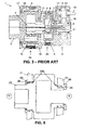
- gearboxes 1 for wind turbines may comprise two planetary gear units 2 and a one-stage parallel gear unit 3. This is illustrated in Fig. 3 .
- the gearbox 1 comprises a first planetary gear unit 2a, a second planetary gear unit 2b and a one-stage parallel gear unit 3.
- Each of the planetary gear units 2a, 2b comprises a planet carrier 4 which supports a plurality of planet gears 5, a ring gear 6 and a sun gear 7.
- the parallel gear unit 3 of the present example differs from the example shown in Fig. 1 and Fig. 2 in that it only comprises a low speed shaft 8 and a high speed shaft 10, and no intermediate shaft 9.
- the low speed shaft 8 and the high speed shaft 10 are rotatably supported by bearings 11.
- the parallel gear unit 3 comprises one gear 16 which is carried on the low speed shaft 8 and the high speed shaft 10 and which meshes with pinion 17 on the high speed shaft 10.
- the planet carrier 4 in the planetary gear unit 2 is rotatably mounted in a housing structure 18 by means of roller bearings 19.
- roller bearings for use in planetary gear units of a gearbox may provide high cost requirements to the manufacturing process of the planetary gear unit because, as a consequence of growing needs for multi-megawatt turbines, sizes of planetary gear unit components keeps increasing.
- speed and load can exceed design limits of rolling bearing solutions. In case of planetary carrier bearings, these design limits could originate from failure modes such as, for example, slip, wear or mixed friction.
- the present invention provides a planetary gear unit for a gearbox for a wind turbine.
- the planetary gear unit comprises a housing and a planet carrier provided with a plurality of planet shafts distributed uniformly around a planet carrier's axis for rotatably supporting planet gears which are mounted between a sun gear and a ring gear for mutual interaction and which are supported by rolling bearings.
- the planet carrier is rotatably mounted in the housing by means of sliding bearings.
- sliding bearings may also be referred to as friction bearings, slide bearings, plain bearings or journal bearings.
- the rolling bearings for supporting the planet gears may be any kind of rolling bearings as known by a person skilled in the art, such as for example but not limited to taper roller bearings, cylindrical roller bearings, spherical roller bearings or CARB toroidal roller bearings.
- the sliding bearings are formed of one single sliding bearing material. This is different from classical, existing sliding bearings which are currently used when big bearings are needed because of high load and speed requirements of the wind turbine and which are formed of a basic design formed out of steel that is provided with a sliding bearing material and which furthermore comprises finishing materials.
- Some examples of material combinations of currently used sliding bearings are steel/bronze, steel/cast bronze alloys, steel/sintered bronze alloys, steel/aluminium-tin alloys, steel/copper-tin alloys, steel/bearing metal, steel/lead-bronze/electroplated layer.
- the sliding bearing material used with the present invention may be any known material suitable for forming sliding bearings and currently used to provide on the steel basic design of classical existing sliding bearings, such as for example but not limited to bronze.
- the sliding bearing may furthermore comprise an additional material on their raceways.
- the sliding bearing raceway design is according to the needs known by a person skilled in the art and taking into account the requirements regarding loads and speed.
- the present invention provides a planetary gear unit comprising a combination of rolling bearings and sliding bearings in a same unit.
- sliding bearings which are different from sliding bearings currently used as planet carrier bearings in combination with rolling bearings at other locations in the planetary gear unit, manufacturing costs of a planetary gear unit according to embodiments of the invention can be significantly decreased.
- the sliding bearings and the planet carrier have raceways for contacting each other and according to embodiments of the invention the raceways of the planet carrier may be hardened.
- the raceways of the planet carrier may be hardened using any process known by a person skilled in the art, such as for example case hardening.
- the raceways of the sliding bearings and the raceways of the planet carrier may be separated by lubricant, or in other words, a lubricant may be provided in between the raceways of the slicing bearings and the raceways of the planet carrier.
- the raceways of the planet carrier may also not be hardened and may, in that case, comprise a hardened ring.
- the planetary gear unit may, according to embodiments of the invention, comprise a radial fixation mechanism at a rotor side of the planetary gear unit and/or at a generator side of the planetary gear unit for preventing the sliding bearings from rotating during operation of the planetary gear unit.
- the locking mechanism may be formed by an additional part different from the sliding bearing such as, for example, by a pin.
- the planetary gear unit may furthermore comprise an axial fixation mechanism.
- the axial fixation mechanism is for preventing axial movement of the sliding bearings of the planetary gear unit during operation of the planetary gear unit and may also be referred to as locking bearing arrangement.
- the axial fixation mechanism may be formed as an integral part of the sliding bearings.
- the axial fixation mechanism may be formed as an additional part different from the sliding bearings, such as for example by a cover provided between the housing and the planet carrier.
- the axial fixation mechanism may be provided at a rotor side of the planetary gear unit and/or at a generator side of the planetary gear unit.
- the planetary gear unit may furthermore comprise a seal, such as for example a sealing ring.
- a seal such as for example a sealing ring.
- the seal may be provided in between the planet carrier and the cover.
- the seal may be provided in between the planet carrier and the sliding bearing.
- the sliding bearings and the housing may be formed of a same material and in one part.
- the present invention provides a gearbox for a wind turbine.
- the gearbox comprises at least one planetary gear unit and a parallel gear unit.
- the planetary gear unit comprises a housing and a planet carrier provided with planet shafts distributed uniformly around a planet carrier's axis for rotatably supporting planet gears which are mounted between a sun gear and a ring gear for mutual interaction and which are supported by rolling bearings, and wherein the planet carrier is rotatably mounted in the housing by means of sliding bearings.
- the sliding bearings may be formed of one single sliding bearing material. This is different from classical, existing sliding bearings which are currently used when big bearings are needed because of high load and speed requirements of the wind turbine and which are formed of a basic design formed out of steel that is provided with a sliding bearing material and which furthermore comprises finishing materials.
- the sliding bearing material used with the present invention may be any known material suitable for forming sliding bearings and currently used to provide on the steel basic design of classical existing sliding bearings, such as for example but not limited to bronze.
- the sliding bearing may furthermore comprise an additional material on their raceways.
- the rolling bearings for supporting the planet gears may be any kind of rolling bearings as known by a person skilled in the art, such as for example but not limited to taper roller bearings, cylindrical roller bearings, spherical roller bearings or CARB toroidal roller bearings.
- the present invention provides a wind turbine comprising a gearbox according to embodiments of the present invention.
- the wind turbine may be a multi-megawatt wind turbine.
- multi-megawatt wind turbine is meant a wind turbine which is able to generate more than 1 megawatt of electricity.
- the wind turbine comprises a gearbox comprising at least one planetary gear unit and a parallel gear unit, the planetary gear unit comprising a housing and a planet carrier provided with planet shafts distributed uniformly around a planet carrier's axis for rotatably supporting planet gears which are mounted between a sun gear and a ring gear for mutual interaction and which are supported by rolling bearings, and wherein the planet carrier is rotatably mounted in the housing by means of sliding bearings.
- the sliding bearings may be formed of one single sliding bearing material. This is different from classical, existing sliding bearings which are currently used when big bearings are needed because of high load and speed requirements of the wind turbine and which are formed of a basic design formed out of steel that is provided with a sliding bearing material and which furthermore comprises finishing materials.
- the sliding bearing material used with the present invention may be any known material suitable for forming sliding bearings and currently used to provide on the steel basic design of classical existing sliding bearings, such as for example but not limited to bronze.
- the sliding bearing may furthermore comprise an additional material on their raceways.
- the rolling bearings for supporting the planet gears may be any kind of rolling bearings as known by a person skilled in the art, such as for example but not limited to taper roller bearings, cylindrical roller bearings, spherical roller bearings or CARB toroidal roller bearings.
- the wind turbine may be of the kind whereby a rotor shaft of the wind turbine is bearing-mounted with two bearings which are fixed directly to the nacelle of the wind turbine.
- the wind turbine may be of the kind whereby one of the bearings of the planet carrier of the planetary gear unit also serves to support the rotor shaft of the wind turbine.
- the present invention provides a planetary gear unit for a gearbox for a wind turbine, a gearbox comprising such a planetary gear unit and a wind turbine comprising such a gearbox. More particularly, the present invention may provide a planetary gear unit for a gearbox for a multi-megawatt wind turbine.
- roller bearings for use in planetary gear units of a gearbox may provide high cost requirements to the manufacturing process of the planetary gear unit because, as a consequence of growing needs for multi-megawatt turbines, sizes of planetary gear unit components keeps increasing.
- the present invention provides a planetary gear unit for a gearbox for a wind turbine.
- the wind turbine may be a multi-megawatt wind turbine.
- multi-megawatt wind turbine is meant a wind turbine which is able to generate more than 1 megawatt of electricity.
- the planetary gear unit comprises a housing and a planet carrier provided with planet shafts distributed uniformly around a planet carrier's axis for rotatably supporting planet gears which are mounted between a sun gear and a ring gear for mutual interaction and which are supported by rolling bearings.
- the planet carrier is rotatably mounted in the housing by means of sliding bearings.
- sliding bearings may also be referred to as friction bearings, slide bearings, plain bearings or journal bearings.
- the sliding bearings may be formed of one single sliding bearing material, which is different from existing sliding bearings which are currently used when big bearings are needed because of high load and speed requirements of the wind turbine.
- the present invention thus provides a planetary gear unit comprising a combination of rolling bearings and sliding bearings.
- sliding bearings which are different from sliding bearings currently used as planet carrier bearings in combination with rolling bearings at other locations in the planetary gear unit, manufacturing costs of a planetary gear unit according to embodiments of the invention can be significantly decreased.
- This is a big advantage nowadays as megawatt requirements for wind turbines, and consequently sizes of parts of, amongst others, the planetary gear unit of the wind turbine, are continuously increasing.
- a gearbox has a rotor side R (for being connected to the rotor hub of the wind turbine) and a generator side G (for being connected to the generator of the wind turbine).
- the rotor side and generator side will be used to indicate locations of different parts in the planetary gear unit.
- locations in the planetary gear unit at rotor side is meant locations before locations of the planet gears.
- locations in the planetary gear unit at generator side is meant locations after location of the planet gears.
- Fig. 4 illustrates a planetary gear unit 20 according to an embodiment of the present invention.
- the planetary gear unit 20 comprises a housing 21 and a planet carrier 22.
- the housing 21 is rigidly connected to a nacelle of the wind turbine (not shown in the figures).
- the planet carrier 22 is, at the rotor side R, connected to a rotor hub of the wind turbine (also not shown in the figures) and serves as input shaft of the planetary gear unit 20.
- the planet carrier 22 comprises a plurality of planet shafts 23 distributed uniformly around the planet carrier's axis for supporting planet gears 24 in a rotatable manner by means of planet bearings 25.
- the planet bearings 25 are rolling bearings.
- the rolling bearings 25 for supporting the planet gears 24 may be any kind of rolling bearings as known by a person skilled in the art, such as for example but not limited to taper roller bearings, cylindrical roller bearings, spherical roller bearings or CARB toroidal roller bearings.
- the planet gears 24 are located between a sun gear 26 and a ring gear 27 for mutual interaction.
- the planet carrier 22 is rotatably mounted in the housing 21 by means of sliding bearings 28 provided both at the rotor side R and the generator side G.
- sliding bearings may also be referred to as friction bearings, slide bearings, plain bearings or journal bearings.
- the sliding bearings are formed of one single sliding bearing material. This is different from classical, existing sliding bearings which are currently used when big bearings are needed because of high load and speed requirements of the wind turbine and which are formed of a basic design formed out of steel that is then provided with a sliding bearing material and which furthermore may comprise finishing materials.
- sliding bearings Some examples of material combinations of currently used sliding bearings are steel/bronze, steel/cast bronze alloys, steel/sintered bronze alloys, steel/aluminium-tin alloys, steel/copper-tin alloys, steel/bearing metal, steel/lead-bronze/electroplated layer.
- the sliding bearing material used with the present invention may be any known material suitable for forming sliding bearings and currently used to provide on the steel basic design of classical existing sliding bearings, such as for example but not limited to bronze.
- the sliding bearing may furthermore comprise an additional material on their raceways.
- the sliding bearings 28 according to embodiments of the invention are cheaper than existing sliding bearings and are also cheaper than the rolling bearings that are currently used as planet carrier bearings in existing planetary gear units for gearboxes for wind turbines. This leads to a lower cost for manufacturing the planetary gear unit 20 according to embodiments of the invention.
- Raceways of the planet carrier 22 may, according to embodiments of the present invention, be hardened.
- the raceways may be hardened using any suitable technique known by a person skilled in the art, such as for example case hardening.
- the raceways of the planet carrier 22 may not be hardened but may instead be provided with a hardened ring.
- the raceways of the sliding bearings 28 and the raceways of the planet carrier 22 may be separated by lubricant, or in other words, a lubricant may be provided in between the raceways of the sliding bearings 28 and the raceways of the planet carrier 22.
- the sliding bearings 28 supporting the planet carrier 22 at the rotor side R may have a same shape as the sliding bearings 28 supporting the planet carrier 22 at the generator side G. According to other embodiments (see further), the sliding bearings 28 supporting the planet carrier 22 at the rotor side R may have a different shape as the sliding bearings 28 supporting the planet carrier 22 at the generator side G.
- the planetary gear unit 20 may furthermore comprise at least one of a radial fixation mechanism and/or at least one axial fixation mechanism.
- the planetary gear unit 20 comprises both a radial fixation mechanism 29 and an axial fixation mechanism 30.
- the radial fixation mechanism 29 for is for preventing the sliding bearings 28 from rotating during operation of the planetary gear unit 20.
- the radial fixation mechanism 29 may be provided at the rotor side R and/or at the generator side G of the planetary gear unit 20. In the present embodiment, the radial fixation mechanism 29 is provided at the rotor side R of the planetary gear unit 20.
- the radial fixation mechanism 29 is formed by an additional part which is different and separate from the sliding bearings 28, such a, for example, a pin 29.
- the radial fixation mechanism 29 may, according to embodiments of the invention, be provided at one of the rotor side R or the generator side G or, according to other embodiments and as is illustrated in Fig. 4 , be provided at both the rotor side R and the generator side G of the planetary gear unit 20.
- the planetary gear unit 20 may furthermore comprise an axial fixation mechanism 30 at the rotor side R and/or at the generator side G of the planetary gear unit 20.
- the presence of an axial fixation mechanism 30 prevents the sliding bearings 28 from moving in axial direction during operation of the planetary gear unit 20.
- the axial fixation mechanism 30 is formed by an additional part which is different and separate from the sliding bearings 28, i.e. cover 30 provided between the housing 21 and the planet carrier 22 at the rotor side R.
- Further axial fixation is provided by the presence of a protrusion 22b of the planet carrier 22, also referred to as planet carrier protrusion 22b.
- Such planet carrier protrusion 22b may, as illustrated in Fig.
- planet carrier protrusions 22b may, according to other embodiments, be provided at only one of the rotor side R or the generator side G.
- the axial fixation mechanism 30 may also be formed as an integral part of the sliding bearings 28 (see further).
- a seal 31 may be provided in between the cover 30 and the planet carrier 22.
- the seal 31 is for substantially perfectly closing off the planetary gear unit 20 for, amongst others, preventing lubricant from leaking out of the planetary gear unit 20.
- the sliding bearings 28 may have different shapes depending on the function or functions that they have to fulfill.
- some different implementations of the sliding bearings 28 and of the planetary gear unit 20 according to the invention will be described. It has to be understood that these are only examples and are not intended to limit the invention in any way.
- Fig. 5 to Fig. 8 for the ease of explanation, only part of the planetary gear unit 20 is shown. It has to be understood that this does not limit the invention in any way.
- Fig. 5a and Fig. 5b illustrate another implementation of the planetary gear unit 20 of the invention.
- an axial fixation mechanism 30 is provided at both the rotor side R and the generator side G.
- the axial fixation mechanism 30 is now formed as an integral part of the sliding bearings 28.
- the shape of the sliding bearings 28 is therefore different from the shape of the sliding bearings 28 in the embodiment of Fig. 4 .
- an axial fixation means is provided both at the rotor side R and the generator side G of the planetary gear unit 20. Again, further axial fixation is provided by the presence of planet carrier protrusions 22b both at the rotor side R and the generator side G of the planetary gear unit 20.
- the planetary gear unit 20 may (see Fig. 5a ) or may not (see Fig. 5b ) comprise a seal 31.
- a seal 31 is provided in between the planet carrier 22 and the sliding bearing 28 at the rotor side R of the planetary gear unit 20.
- Fig. 6 illustrates another embodiment of the planetary gear unit 20 according to the present invention.
- the sliding bearings 28 again have a different shape than described with respect to Fig. 4 and Fig. 5 .
- the planetary gear unit 20 according to the present embodiment comprises an axial fixation mechanism 30 which is formed as an integral part of the sliding bearings 28 at both the rotor side R and the generator side G of the planetary gear unit 20.
- a seal 31 may furthermore be provided in between the sliding bearings 28 and the planet carrier 22.
- FIG. 7 Another embodiment of the planetary gear unit 20 according to the invention is illustrated in Fig. 7 .
- the sliding bearings 28 provided at the rotor side R and the generator side R of the planetary gear unit 20 have a same shape. This is, however, not necessarily so.
- Fig. 7 illustrates an embodiment in which the sliding bearings 28 at the rotor side R have a different shape than the sliding bearings 28 at the generator side G of the planetary gear unit 20.
- the different shape of the sliding bearings 28 at rotor side R and generator side G originates from the fact that at the rotor side R an axial fixation mechanism 30 is provided which is formed as an integral part of the sliding bearings 28.
- the planetary gear unit 20 may furthermore comprise a radial fixation mechanism in the form of pin 29 at the generator side G.
- a seal 31 may be provided in between the planet carrier 22 and the sliding bearing 28 at the rotor side R of the planetary gear unit 20.
- Fig. 8 illustrates another embodiment of the planetary gear unit 20 according to the invention.
- the housing 21 and the sliding bearings 28 are formed of a same material and in one part.
- An axial fixation mechanism is provided as a separate part different from the sliding bearings 28, i.e. as a cover 30 provided in between the housing/bearing 21/28 and the planet carrier 22 at the rotor side R of the planetary gear unit 20.
- a seal 31 is provided in between the cover 30 and the planet carrier 22 at the rotor side R of the planetary gear unit 20.
- an axial fixation mechanism 30 is also provided at the generator side G of the planetary gear unit 20. Similar as at the rotor side R of the planetary gear unit 20, the axial fixation mechanism is provided as a separate part different from the sliding bearings 28, i.e. as a cover 30..
- Fig. 9 still another embodiment of the planetary gear unit 20 according to the invention is illustrated.
- the planetary gear unit 20 according to the present example comprises at the rotor side R an axial fixation mechanism in the form of a cover 30 for preventing the sliding bearing 28 from moving in the axial direction during operation of the planetary gear unit. Further axial fixation is provided by the presence of a protrusion 21 b of the housing 21, also referred to as housing protrusion 21 b.
- housing protrusion 21 b may, as illustrated in Fig. 9 , preferably be provided both at the rotor side R and the generator side G of the planetary gear unit 20. However, this is not necessarily so, housing protrusions 21b may, according to other embodiments, be provided at only one of the rotor side R or the generator side G of the planetary gear unit 20.
- a seal 31 is provided in between the cover 30 and the planet carrier 22.
- the sliding bearing 28 is axially blocked by a further axial fixation mechanism 30.
- the present invention thus teaches to use a combination of rolling bearings and sliding bearings in one planetary gear unit.
- sliding bearings which are different from sliding bearings currently used as planet carrier bearings, in combination with rolling bearings at other locations in the planetary gear unit, manufacturing costs of a planetary gear unit according to embodiments of the invention can be significantly decreased.
- the planetary gear unit 20 may be applied to wind turbines whereby a rotor shaft of the wind turbine is bearing-mounted with two bearings which are fixed directly to the nacelle of the wind turbine.
- the planetary gear unit 20 according to embodiments of the invention may be applied to wind turbines whereby one of the bearings of the planet carrier of the planetary gear unit 20 also serves to support the rotor shaft of the wind turbine.
- a gearbox 40 is provided.
- the gearbox comprises at least one planetary gear unit 20 and a parallel gear unit 41.
- the parallel gear unit 41 may comprise at least two parallel shafts.
- the parallel gear unit 41 may be a one-stage or a two-stage parallel gear unit.
- the parallel gear unit 41 may be a two-stage parallel gear unit comprising a high speed shaft 32, an intermediate shaft 33 and a low speed shaft 34 which are all parallel to each other and which are each rotatably supported by bearings 35.
- At least one of the shafts 32, 33, 34 may be supported by roller bearings.
- each of the shafts 32, 33, 34 may be supported by roller bearings 35.
- one of the shafts may be supported by sliding bearings while the other shaft(s) may be supported by roller bearings.
- the high speed shaft 32 of the parallel unit 41 may be supported by sliding bearings
- the intermediate shaft 33 and the low speed shaft 34 of the parallel gear unit 41 may be supported by roller bearings.
- the parallel gear unit 41 furthermore comprises two gears 36, 37.
- One gear 36 is carried on the low speed shaft 34 and the intermediate shaft 33 and the other gear 37 is carried on the intermediate shaft 33 and the high speed shaft 34.
- the gears 36, 37 respectively mesh with pinion 38 on the intermediate shaft 33 and pinion 39 on the high speed shaft 32.
- the planetary gear unit 20 may be any planetary gear unit 20 as described with respect to the first aspect of the invention.
- the planetary gear unit 20 comprises a housing 21 and a planet carrier 22 provided with planet shafts 23 distributed uniformly around a planet carrier's axis for rotatably supporting planet gears 24 which are mounted between a sun gear 26 and a ring gear 27 for mutual interaction and which are supported by rolling bearings 25.
- the planet carrier 22 is rotatably mounted in the housing 21 by means of sliding bearings 28 both at the rotor side R and the generator side G of the planetary gear unit 20.
- the sliding bearings 28 are formed of one single sliding bearing material. This is different from classical, existing sliding bearings which are currently used when big bearings are needed because of high load and speed requirements of the wind turbine and which are formed of a basic design formed out of steel that is then provided with a sliding bearing material and which furthermore comprises finishing materials.
- the sliding bearing material used with the present invention may be any known material suitable for forming sliding bearings and currently used to provide on the steel basic design of classical existing sliding bearings, such as for example but not limited to bronze.
- the sliding bearing may furthermore comprise an additional material on their raceways.
- the sliding bearings 28 according to embodiments of the invention are cheaper than existing sliding bearings and are also cheaper than the rolling bearings that are currently used as planet carrier bearings in existing planetary gear units for gearboxes for wind turbines. This leads to a lower cost for manufacturing the planetary gear unit 20 according to embodiments of the invention.
- the rolling bearings 25 for supporting the planet gears 24 may be any kind of rolling bearings as known by a person skilled in the art, such as for example but not limited to taper roller bearings, cylindrical roller bearings, spherical roller bearings or CARB toroidal roller bearings.
- Fig. 9 illustrates an embodiment of a gearbox 40 according to the invention.
- the sliding bearings 28 provided at the rotor side R of the planetary gear unit 20 have a different shape than the sliding bearings 28 provided at the generator side G of the planetary gear unit 20.
- the different shape of the sliding bearings 28 at rotor side R and generator side G originates from the fact that at the rotor side R an axial fixation mechanism 30 is provided which is formed as an integral part of the sliding bearings 28 for preventing the sliding bearings 28 from moving in axial direction during operation of the planetary gear unit 20.
- the sliding bearings 28 provided at the rotor side R of the planetary gear unit 20 may have a same shape than the sliding bearings 28 provided at the generator side G of the planetary gear unit 20.
- the axial fixation mechanism 30 may also be provided as an additional part different from the sliding bearings 28, such as for example a cover.
- a seal 31 is provided in between the planet carrier 22 and the sliding bearing 28 at the rotor side R of the planetary gear unit 20 for substantially perfectly closing off the planetary gear unit 20 for, amongst others, preventing lubricant from leaking out of the planetary gear unit 20.
- a gearbox 40 may comprise any planetary gear unit 20 as described in the first aspect of this invention.
- the gearbox 40 according to embodiments of the invention may be applied to wind turbines whereby a rotor shaft of the wind turbine is bearing-mounted with two bearings which are fixed directly to the nacelle of the wind turbine.
- the gearbox 40 according to embodiments of the invention may be applied to wind turbines whereby one of the bearings of the planet carrier of the planetary gear unit 20 also serves to support the rotor shaft of the wind turbine.
- a wind turbine comprising a gearbox 40 comprising at least one planetary gear unit 20 and a parallel gear unit 41.
- the parallel gear unit 41 may be any parallel gear unit 41 as described above with respect to the second aspect of the invention.
- the planetary gear unit 20 comprises a housing 21 and a planet carrier 22 provided with planet shafts 23 distributed uniformly around a planet carrier's axis for rotatably supporting planet gears 24 which are mounted between a sun gear 26 and a ring gear 27 for mutual interaction and which are supported by rolling bearings 25.
- the planet carrier 22 is rotatably mounted in the housing 21 by means of sliding bearings 28 both at the rotor side R and the generator side G of the planetary gear unit 20.
- the sliding bearings are formed of one single sliding bearing material. This is different from classical, existing sliding bearings which are currently used when big bearings are needed because of high load and speed requirements of the wind turbine and which are formed of a basic design formed out of steel that is then provided with a sliding bearing material and which furthermore comprises finishing materials.
- the sliding bearing material used with the present invention may be any known material suitable for forming sliding bearings and currently used to provide on the steel basic design of classical existing sliding bearings, such as for example but not limited to bronze.
- the sliding bearing may furthermore comprise an additional material on their raceways.
- the sliding bearings 28 according to embodiments of the invention are cheaper than existing sliding bearings and are also cheaper than the rolling bearings that are currently used as planet carrier bearings in existing planetary gear units for gearboxes for wind turbines. This leads to a lower cost for manufacturing the planetary gear unit 20 according to embodiments of the invention.
- the rolling bearings 25 for supporting the planet gears 24 may be any kind of rolling bearings as known by a person skilled in the art, such as for example but not limited to taper roller bearings, cylindrical roller bearings, spherical roller bearings or CARB toroidal roller bearings.
- a wind turbine according to the invention may comprise any gearbox 40 as described with reference to the second aspect of this invention.
- the gearbox 40 may comprise any planetary gear unit 20 as described in the first aspect of this invention.
- the wind turbine may be of the kind whereby a rotor shaft of the wind turbine is bearing-mounted with two bearings which are fixed directly to the nacelle of the wind turbine.
- the wind turbine may be of the kind whereby one of the bearings of the planet carrier of the planetary gear unit 20 also serves to support the rotor shaft of the wind turbine.
Landscapes
- Engineering & Computer Science (AREA)
- General Engineering & Computer Science (AREA)
- Mechanical Engineering (AREA)
- Life Sciences & Earth Sciences (AREA)
- Sustainable Development (AREA)
- Sustainable Energy (AREA)
- Chemical & Material Sciences (AREA)
- Combustion & Propulsion (AREA)
- General Details Of Gearings (AREA)
- Wind Motors (AREA)
- Retarders (AREA)
Applications Claiming Priority (1)
| Application Number | Priority Date | Filing Date | Title |
|---|---|---|---|
| GB0917018A GB2473875A (en) | 2009-09-28 | 2009-09-28 | Wind turbine gearbox with planetary gear unit having sliding bearings |
Publications (2)
| Publication Number | Publication Date |
|---|---|
| EP2302257A2 true EP2302257A2 (de) | 2011-03-30 |
| EP2302257A3 EP2302257A3 (de) | 2011-08-10 |
Family
ID=41350504
Family Applications (1)
| Application Number | Title | Priority Date | Filing Date |
|---|---|---|---|
| EP10009530A Withdrawn EP2302257A3 (de) | 2009-09-28 | 2010-09-14 | Planetengetriebeeinheit für ein Getriebe für ein Windrad, Getriebe für ein Windrad und Windrad |
Country Status (6)
| Country | Link |
|---|---|
| US (1) | US20110077120A1 (de) |
| EP (1) | EP2302257A3 (de) |
| CN (1) | CN102032122A (de) |
| AU (1) | AU2010224321A1 (de) |
| CA (1) | CA2714845A1 (de) |
| GB (1) | GB2473875A (de) |
Cited By (5)
| Publication number | Priority date | Publication date | Assignee | Title |
|---|---|---|---|---|
| EP2568197A1 (de) * | 2011-09-12 | 2013-03-13 | Jtekt Corporation | Stromerzeugungsvorrichtung |
| US9054560B2 (en) | 2012-04-19 | 2015-06-09 | Jtekt Corporation | Power generating apparatus |
| US9097295B2 (en) | 2012-10-03 | 2015-08-04 | Jtekt Corporation | Power generation device |
| EP2933483A1 (de) * | 2014-04-15 | 2015-10-21 | Siemens Aktiengesellschaft | Antriebssystem einer Windkraftanlage |
| EP2975299A1 (de) * | 2014-07-18 | 2016-01-20 | Siemens Aktiengesellschaft | Gleitlagerung für Planetenträger |
Families Citing this family (13)
| Publication number | Priority date | Publication date | Assignee | Title |
|---|---|---|---|---|
| AU2010201624B2 (en) * | 2010-02-12 | 2011-10-13 | Mitsubishi Heavy Industries, Ltd. | Gear box for wind turbine generator and wind turbine generator |
| CA2694130C (en) * | 2010-02-12 | 2013-04-16 | Mitsubishi Heavy Industries, Ltd. | Gear box for wind turbine generator and wind turbine generator |
| GB201104455D0 (en) * | 2011-03-16 | 2011-04-27 | Romax Technology Ltd | Cover and sealing arrangements for a wind turbine gearbox |
| US8414448B2 (en) | 2011-08-31 | 2013-04-09 | General Electric Company | Gear system for wind turbine |
| JP6136390B2 (ja) | 2013-03-12 | 2017-05-31 | 株式会社ジェイテクト | 風力発電装置用の一方向クラッチ及び一方向クラッチユニット |
| DE102013226527A1 (de) * | 2013-12-18 | 2015-06-18 | Zf Friedrichshafen Ag | Kombinierte Wälz- und Gleitlagerung einer Getriebewelle |
| US11078888B2 (en) * | 2016-08-04 | 2021-08-03 | Flender Gmbh | Wind turbine transmission |
| EP3343071A1 (de) * | 2017-01-02 | 2018-07-04 | Moventas Gears Oy | Planetenradträger für ein planetengetriebe |
| US10495185B2 (en) * | 2017-03-06 | 2019-12-03 | Fairfield Manufacturing Company, Inc. | Planetary wheel drive using bushings |
| US10066735B1 (en) | 2017-03-06 | 2018-09-04 | Fairfield Manufacturing Company, Inc. | Planetary wheel drive single wall lugged output carrier |
| US10816086B2 (en) | 2017-08-14 | 2020-10-27 | General Electric Company | Power gearbox gear arrangement |
| CN107387681B (zh) * | 2017-08-24 | 2019-09-24 | 宁波吉利汽车研究开发有限公司 | 一种变速器行星轮系机构 |
| US11867278B1 (en) * | 2022-09-28 | 2024-01-09 | Enplas Corporation | Planetary gear device |
Family Cites Families (9)
| Publication number | Priority date | Publication date | Assignee | Title |
|---|---|---|---|---|
| US1399549A (en) * | 1918-03-11 | 1921-12-06 | Curran W Harvey | Resilient gear |
| GB454771A (en) * | 1935-05-22 | 1936-10-07 | Gen Motors Corp | Improvements relating to bearings |
| DE1165370B (de) * | 1958-02-21 | 1964-03-12 | Wilhelm G Stoeckicht Dipl Ing | Stirnraederplanetengetriebe |
| GB957612A (en) * | 1960-09-27 | 1964-05-06 | Cammell Laird & Company Shipbu | Improvements in or relating to machine bearings |
| DE2620570C3 (de) * | 1976-05-10 | 1982-09-09 | Bhs-Bayerische Berg-, Huetten- Und Salzwerke Ag, 8000 Muenchen | Einfach-schrägverzahntes Stirnräder-Planetengetriebe mit Lastausgleich |
| FR2566868B1 (fr) * | 1984-06-29 | 1990-01-05 | Paris & Du Rhone | Reducteur epicycloidal a blocage centrifuge |
| EP0719964B1 (de) * | 1995-01-02 | 1999-08-25 | Günther Heidrich | Stirnräderplanetengetriebe |
| JP2004084815A (ja) * | 2002-08-27 | 2004-03-18 | Komatsu Ltd | 軸受装置 |
| DE10302192B4 (de) * | 2003-01-20 | 2014-08-28 | Siemens Aktiengesellschaft | Planetengetriebe mit einer Ausgleichskupplung |
-
2009
- 2009-09-28 GB GB0917018A patent/GB2473875A/en not_active Withdrawn
-
2010
- 2010-09-14 EP EP10009530A patent/EP2302257A3/de not_active Withdrawn
- 2010-09-15 CA CA2714845A patent/CA2714845A1/en not_active Abandoned
- 2010-09-17 AU AU2010224321A patent/AU2010224321A1/en not_active Abandoned
- 2010-09-21 CN CN2010102958271A patent/CN102032122A/zh active Pending
- 2010-09-24 US US12/889,443 patent/US20110077120A1/en not_active Abandoned
Non-Patent Citations (1)
| Title |
|---|
| None |
Cited By (11)
| Publication number | Priority date | Publication date | Assignee | Title |
|---|---|---|---|---|
| EP2568197A1 (de) * | 2011-09-12 | 2013-03-13 | Jtekt Corporation | Stromerzeugungsvorrichtung |
| US9035476B2 (en) | 2011-09-12 | 2015-05-19 | Jtekt Corporation | Power generating device |
| US9322395B2 (en) | 2011-09-12 | 2016-04-26 | Jtekt Corporation | Power generating device |
| US9054560B2 (en) | 2012-04-19 | 2015-06-09 | Jtekt Corporation | Power generating apparatus |
| US9097295B2 (en) | 2012-10-03 | 2015-08-04 | Jtekt Corporation | Power generation device |
| EP2933483A1 (de) * | 2014-04-15 | 2015-10-21 | Siemens Aktiengesellschaft | Antriebssystem einer Windkraftanlage |
| WO2015158753A1 (de) * | 2014-04-15 | 2015-10-22 | Siemens Aktiengesellschaft | Antriebssystem einer windkraftanlage |
| US10316826B2 (en) | 2014-04-15 | 2019-06-11 | Siemens Aktiengesellschaft | Drive system of a wind turbine |
| EP2975299A1 (de) * | 2014-07-18 | 2016-01-20 | Siemens Aktiengesellschaft | Gleitlagerung für Planetenträger |
| WO2016008737A1 (de) * | 2014-07-18 | 2016-01-21 | Siemens Aktiengesellschaft | Gleitlagerung für planetenträger |
| US9920830B2 (en) | 2014-07-18 | 2018-03-20 | Flender Gmbh | Sliding bearing for planet carrier |
Also Published As
| Publication number | Publication date |
|---|---|
| EP2302257A3 (de) | 2011-08-10 |
| US20110077120A1 (en) | 2011-03-31 |
| GB0917018D0 (en) | 2009-11-11 |
| AU2010224321A1 (en) | 2011-04-14 |
| CN102032122A (zh) | 2011-04-27 |
| GB2473875A (en) | 2011-03-30 |
| CA2714845A1 (en) | 2011-03-28 |
Similar Documents
| Publication | Publication Date | Title |
|---|---|---|
| EP2302257A2 (de) | Planetengetriebeeinheit für ein Getriebe für ein Windrad, Getriebe für ein Windrad und Windrad | |
| EP2284420B1 (de) | Paralleler Getriebeblock für ein Getriebe für ein Windrad | |
| EP2847497B1 (de) | Planetengetriebestufe mit gleitlagern als planetenlager und verwendung | |
| CN202182159U (zh) | 用于风力发电设备的行星齿轮变速器 | |
| US20050148425A1 (en) | Cylindrical roller bearing and planetary gear assembly utilizing the same | |
| WO2011074332A1 (ja) | 風力発電設備用変速機および風力発電装置 | |
| US8794094B2 (en) | Parallel gear unit for a gearbox for a wind turbine | |
| US20030125158A1 (en) | Planetary gear stage | |
| US10358941B2 (en) | Gas turbine engine | |
| US11085492B2 (en) | Roller bearing | |
| US20190032708A1 (en) | Bearing arrangement for supporting a shaft of a gearbox | |
| EP3739227A1 (de) | Lager für einen windturbinenantriebsstrang mit einem elastomerträger | |
| JP2008303893A (ja) | 円筒ころ軸受 | |
| WO2024016324A1 (zh) | 行星齿轮箱和风电设备 |
Legal Events
| Date | Code | Title | Description |
|---|---|---|---|
| PUAI | Public reference made under article 153(3) epc to a published international application that has entered the european phase |
Free format text: ORIGINAL CODE: 0009012 |
|
| AK | Designated contracting states |
Kind code of ref document: A2 Designated state(s): AL AT BE BG CH CY CZ DE DK EE ES FI FR GB GR HR HU IE IS IT LI LT LU LV MC MK MT NL NO PL PT RO SE SI SK SM TR |
|
| AX | Request for extension of the european patent |
Extension state: BA ME RS |
|
| PUAL | Search report despatched |
Free format text: ORIGINAL CODE: 0009013 |
|
| AK | Designated contracting states |
Kind code of ref document: A3 Designated state(s): AL AT BE BG CH CY CZ DE DK EE ES FI FR GB GR HR HU IE IS IT LI LT LU LV MC MK MT NL NO PL PT RO SE SI SK SM TR |
|
| AX | Request for extension of the european patent |
Extension state: BA ME RS |
|
| RIC1 | Information provided on ipc code assigned before grant |
Ipc: F16H 37/04 20060101ALN20110705BHEP Ipc: F03D 11/02 20060101ALI20110705BHEP Ipc: F16H 57/08 20060101ALI20110705BHEP Ipc: F16H 1/28 20060101AFI20110705BHEP |
|
| RAP1 | Party data changed (applicant data changed or rights of an application transferred) |
Owner name: HANSEN TRANSMISSIONS INTERNATIONAL N.V. |
|
| STAA | Information on the status of an ep patent application or granted ep patent |
Free format text: STATUS: THE APPLICATION IS DEEMED TO BE WITHDRAWN |
|
| 18D | Application deemed to be withdrawn |
Effective date: 20120211 |