EP2301800B1 - Device for dispensing liquid media from individual chambers of a tanker - Google Patents
Device for dispensing liquid media from individual chambers of a tanker Download PDFInfo
- Publication number
- EP2301800B1 EP2301800B1 EP10009365.7A EP10009365A EP2301800B1 EP 2301800 B1 EP2301800 B1 EP 2301800B1 EP 10009365 A EP10009365 A EP 10009365A EP 2301800 B1 EP2301800 B1 EP 2301800B1
- Authority
- EP
- European Patent Office
- Prior art keywords
- valve
- control device
- collector
- signal
- sensor
- Prior art date
- Legal status (The legal status is an assumption and is not a legal conclusion. Google has not performed a legal analysis and makes no representation as to the accuracy of the status listed.)
- Active
Links
- 239000007788 liquid Substances 0.000 title claims description 12
- 238000012544 monitoring process Methods 0.000 claims description 18
- 239000012530 fluid Substances 0.000 claims 2
- 238000000034 method Methods 0.000 description 8
- 238000005086 pumping Methods 0.000 description 3
- 230000005484 gravity Effects 0.000 description 2
- 230000008878 coupling Effects 0.000 description 1
- 238000010168 coupling process Methods 0.000 description 1
- 238000005859 coupling reaction Methods 0.000 description 1
- 230000003111 delayed effect Effects 0.000 description 1
- 230000001419 dependent effect Effects 0.000 description 1
- 238000001514 detection method Methods 0.000 description 1
- 238000005429 filling process Methods 0.000 description 1
- 238000005259 measurement Methods 0.000 description 1
- 239000000203 mixture Substances 0.000 description 1
- 230000036316 preload Effects 0.000 description 1
- 238000004064 recycling Methods 0.000 description 1
- 238000007789 sealing Methods 0.000 description 1
- 238000013022 venting Methods 0.000 description 1
Images

Classifications
-
- B—PERFORMING OPERATIONS; TRANSPORTING
- B60—VEHICLES IN GENERAL
- B60P—VEHICLES ADAPTED FOR LOAD TRANSPORTATION OR TO TRANSPORT, TO CARRY, OR TO COMPRISE SPECIAL LOADS OR OBJECTS
- B60P3/00—Vehicles adapted to transport, to carry or to comprise special loads or objects
- B60P3/22—Tank vehicles
- B60P3/224—Tank vehicles comprising auxiliary devices, e.g. for unloading or level indicating
- B60P3/2245—Adaptations for loading or unloading
Definitions
- the senor may be designed so that it only responds under pressure at a certain liquid flow. For example, if gas is routed through the return port or into the conduit section between the return port and the check valve, the sensor will not generate a monitor signal, or the signal from the sensor will not be considered by the sensor to indicate proper feedback in the controller. A manipulation with compressed air, as far as it is available on the tanker, is thus excluded.
- the return port for the dispensing gun is associated with a compressed air port.
- the compressed air is used to free the liquid between the port and the check valve when the recirculation is finished.
- the dispensing gun is still connected to the port.
Description
Die Erfindung bezieht sich auf eine Vorrichtung zur Abgabe von flüssigen Medien aus einzelnen Kammern eines Tankwagens nach dem Anspruch 1.The invention relates to a device for dispensing liquid media from individual chambers of a tanker truck according to claim 1.
Tankwagen weisen bekanntlich mehrere Kammern auf, die gegebenenfalls mit unterschiedlichen Medien befüllt werden. Zu Befüll- und Entnahmezwecken ist jeder Kammer ein Bodenventil zugeordnet, das über einen Leitungsabschnitt mit einem Kollektor verbunden ist. An den Kollektor schließt sich die Abgabeleitung an, die am Ende mit einem Abgabeschlauch in Verbindung steht. Dieser ist zumeist auf einer Trommel aufgewickelt und weist am Ende eine Abgabepistole auf. In der Abgabeleitung befinden sich eine Förderpumpe und ein Volumenzähler. Ausgangsseitig des Volumenzählers ist ein Absperrventil vorgesehen. Im Verbindungsbereich der Leitungsabschnitte mit dem Kollektor ist außerdem ein Kollektorventil angeordnet. Mit dem Leitungsabschnitt ist außerdem eine Befüllkupplung sowie ein Befüllventil verbunden, um die Befüllung der Kammern in einem Depot über das Bodenventil vorzusehen.Tankers are known to have several chambers, which may be filled with different media. For filling and removal purposes, each chamber is associated with a bottom valve, which is connected via a line section with a collector. The collector is followed by the discharge line, which is connected to a discharge hose at the end. This is usually wound on a drum and has at the end of a dispensing gun. The delivery line contains a feed pump and a volume meter. On the output side of the volumetric meter a shut-off valve is provided. In the connection region of the line sections with the collector, a collector valve is also arranged. In addition, a filling coupling and a filling valve are connected to the line section in order to provide the filling of the chambers in a depot via the bottom valve.
Aus
Die Rückführung bei einem Vollschlauchsystem bei einer bekannten Vorrichtung ist wie folgt: Nach Beendigung der Abgabe wird die Pumpe gestoppt oder das Abgabeventil geschlossen. Das Bodenventil der Tankkammer, aus dem ein Produkt abgegeben wurde, wird geschlossen. Die Pistole des Abgabeschlauchs wird mit dem Rückführungsanschluss verbunden. Optional kann der Kollektor bei offener Entlüftung und Absenken des Flüssigkeitsniveaus bis vor die Pumpe entleert werden. Ansonsten erfolgt die Leerung vollständig über das neu abzugebende Produkt aus einer anderen Tankkammer. Danach öffnet das Bodenventil der Kammer mit dem neuen Produkt. Die Pumpe wird wieder gestartet oder das Abgabeventil geöffnet. Es wird soviel Flüssigkeit aus der neuen Kammer gepumpt, bis das neue Produkt am Schlauchende, d.h. an der Pistole, ankommt. Dies kann ohne Weiteres dadurch festgestellt werden, dass der Volumenzähler die durch die Abgabeleitung strömende Menge misst. Das Volumen dieses Leitungsabschnitts ist bekannt. Wurde zuvor der Kollektor entleert, kann auch dies ohne Weiteres mit einbezogen werden, da auch das Volumen des Kollektors naturgemäß bekannt ist. Das Abgabeventil wird geschlossen oder die Pumpe gestoppt. Die Abgabepistole wird am Schlauchende geschlossen. Schließlich wird Druckluft auf den Raum zwischen Anschluss der Pistole und der Verbindung zur Abgabeleitung gegeben, damit dieser keine Flüssigkeit mehr enthält. Schließlich wird die Abgabepistole vom Rückführungsanschluss entfernt.The return in a full hose system in a known device is as follows: After completion of the dispensing, the pump is stopped or the dispensing valve is closed. The bottom valve of the tank chamber from which a product was dispensed is closed. The gun of the delivery hose is connected to the return port. Optionally, the collector can be emptied with open venting and lowering the liquid level to the front of the pump. Otherwise, emptying takes place completely via the new product to be dispensed from another tank chamber. Thereafter, the bottom valve of the chamber opens with the new product. The pump is restarted or the dispensing valve opened. As much liquid is pumped from the new chamber until the new product at the end of the tube, i. at the gun, arrives. This can be readily ascertained by the volume meter measuring the amount flowing through the dispensing line. The volume of this line section is known. Was previously emptied the collector, this can also be included without further, since the volume of the collector is naturally known. The dispensing valve is closed or the pump is stopped. The dispensing gun is closed at the end of the hose. Finally, compressed air is added to the space between the gun port and the connection to the discharge line so that it no longer contains any liquid. Finally, the dispensing gun is removed from the return port.
Wie ersichtlich befindet sich nach Beendigung des Abgabevorgangs ein erhebliches Produktvolumen in der Abgabeleitung und im Abgabeschlauch. Es besteht Gefahr, dass die Bedienungsperson dieses Volumen nicht in die betreffende Kammer zurückleitet, sondern zu anderen Zwecken abzweigt. Dies kann mit den vorhandenen Mitteln eines Abgabesystems nicht festgestellt werden. Es besteht ferner die Gefahr, dass der Bediener bei der Rückführung das Medium in eine falsche Tankkammer rückleitet. Dies entweder zu Betrugszwecken oder auch irrtümlich. Schließlich kann eine Manipulation darin bestehen, dass der Bediener vor einer Abgabe an einen Kundentank den Volumenzähler hochtreibt und erst dann die Abgabepistole an den Kundentank anschließt. Hierbei erfolgt ein Umpumpen des Mediums im Kreis ohne eine zwischenzeitliche Nullstellung des Volumenzählers, bevor die Pistole an den Kundentank gekoppelt wird.As can be seen, there is a considerable volume of product in the discharge line and in the discharge hose after completion of the dispensing process. There is a risk that the operator of this volume does not return to the relevant chamber, but branches off for other purposes. This can be done with the existing ones Means of a delivery system can not be determined. There is also a risk that the operator returns the medium in an incorrect tank chamber during the return. This either for fraud or even mistaken. Finally, a manipulation can be that the operator drives up the volume counter before delivering it to a customer's tank and only then connects the dispensing gun to the customer's tank. This involves pumping the medium in a circle without an intermediate zero position of the volumetric meter before the pistol is coupled to the customer tank.
Der Erfindung liegt daher die Aufgabe zugrunde, eine Vorrichtung zur Abgabe von flüssigen Medien aus einzelnen Kammern eines Tankwagens anzugeben, bei der die Rückführung von Produkt aus dem Leitungssystem der Abgabevorrichtung in eine Kammer überwacht wird.The invention is therefore based on the object to provide a device for dispensing liquid media from individual chambers of a tank truck, in which the return of product from the piping system of the dispenser is monitored in a chamber.
Diese Aufgabe wird durch die Merkmale des Anspruchs 1 gelöst.This object is solved by the features of claim 1.
Bei der erfindungsgemäßen Vorrichtung ist dem Anschluss für die Rückführung vor oder hinter dem Rückschlagventil ein Sensor zugeordnet, der ein Überwachungssignal auf eine Steuervorrichtung der Abgabevorrichtung gibt, wenn ein flüssiges Medium durch den Anschluss strömt.In the device according to the invention, the connection for the return before or after the check valve, a sensor is assigned, which gives a monitoring signal to a control device of the dispenser when a liquid medium flows through the terminal.
Nach einer Ausgestaltung der Erfindung überwacht die Steuervorrichtung, ob das erste Anlaufsignal von dem Volumenzähler und das Überwachungssignal des Sensors innerhalb eines vorgegebenen Zeitfensters erscheinen. Hierbei wird berücksichtigt, dass der Volumenzähler bei der Rückführung zuerst anläuft, bevor das Medium über den Rückführungsanschluss strömt und das Rückschlagventil im Anschluss für die Rückführung öffnet. Das Ansprechen des Sensors ist damit naturgemäß zeitverzögert. Diese Verzögerungszeit wird als Sicherheitsmaßnahme gegen Manipulation im Zeitfenster überwacht. Der gleiche Vorgang kann bei Beendigung der Rückführung erfolgen. Auch hierbei wird das vom Volumenzählersignal und vom Sensorsignal gebildete Zeitfenster in der Steuervorrichtung überwacht.According to one embodiment of the invention, the control device monitors whether the first start signal from the volume counter and the monitoring signal of the sensor appear within a predetermined time window. This takes into account that the volume counter starts first during the return, before the medium flows over the return connection and the check valve then opens for the return. The response of the sensor is thus naturally delayed. This delay time is considered a safety measure monitored against manipulation in the time window. The same process can be done at the completion of the return. Here, too, the time window formed by the volume counter signal and the sensor signal is monitored in the control device.
Nach einer weiteren Ausgestaltung der Erfindung wird das Überwachungssignal und das Signal vom Volumenzähler in der Steuervorrichtung in Beziehung gesetzt, und die Steuervorrichtung erzeugt ein Rückführungssignal bei einer vorgegebenen Beziehung. Mit Hilfe des Sensors kann das durch den Anschluss fließende Volumen bestimmt und mit dem vom Volumenzähler gemessenen Volumen verglichen werden. Stimmen die Messwerte nicht überein, liegt eine Manipulation vor.According to a further embodiment of the invention, the monitoring signal and the signal from the volume counter in the control device are related, and the control device generates a feedback signal at a predetermined relationship. With the help of the sensor, the volume flowing through the connection can be determined and compared with the volume measured by the volume meter. If the measured values do not match, there is a manipulation.
Nach einer weiteren Ausgestaltung der Erfindung kann der Sensor so ausgelegt sein, dass er nur bei einem bestimmten Flüssigkeitsstrom unter Druck anspricht. Wird zum Beispiel Gas über den Rückführanschluss geleitet bzw. in den Leitungsabschnitt zwischen dem Rückführungsanschluss und dem Rückschlagventil, wird vom Sensor kein Überwachungssignal erzeugt bzw. wird in der Steuervorrichtung das Signal vom Sensor nicht als eine ordnungsgemäße Rückführung anzeigend betrachtet. Eine Manipulation mit Druckluft, soweit sie am Tankfahrzeug zur Verfügung steht, ist damit ausgeschlossen.According to a further embodiment of the invention, the sensor may be designed so that it only responds under pressure at a certain liquid flow. For example, if gas is routed through the return port or into the conduit section between the return port and the check valve, the sensor will not generate a monitor signal, or the signal from the sensor will not be considered by the sensor to indicate proper feedback in the controller. A manipulation with compressed air, as far as it is available on the tanker, is thus excluded.
Nach einer anderen Ausgestaltung der Erfindung sind in der Steuervorrichtung die Überwachungssignale der Sensoren den Kammern bzw. den Bodenventilen der Kammern zugeordnet. Die Steuervorrichtung stellt fest, in welche Kammer eine Rückführung erfolgt. Dadurch ist es möglich, die Rückführung automatisch zu stoppen, wenn die Abgabepistole nicht an den zutreffenden Anschluss gekoppelt ist. Auf diese Weise wird eine unerwünschte Produktvermischung vermieden oder aber eine Manipulation, wenn z.B. der Bediener das rückgeführte Produkt in eine leere Tankkammer leitet, um es anschließend zu entwenden.According to another embodiment of the invention, the monitoring signals of the sensors are assigned to the chambers or the bottom valves of the chambers in the control device. The control device determines in which chamber a return takes place. This makes it possible to stop the feedback automatically if the dispensing gun is not coupled to the appropriate port. In this way, an undesirable product mixing is avoided or a manipulation, for example, when the operator directs the returned product in an empty tank chamber to then steal it.
Schließlich wird eine weitere Manipulationsmöglichkeit dadurch verhindert, dass die Steuervorrichtung nach Beendigung eines Pumpvorgangs den Volumenzähler automatisch auf Null zurückstellt. Dadurch wird vermieden, dass der Volumenzähler durch Umpumpen im Kreislauf eine Abgabemenge fingiert, die in Wirklichkeit nicht an einen Kunden gegeben wurde und die anschließend entwendet wird. Die erfindungsgemäße Vorrichtung macht eine solche Manipulation erkennbar oder unmöglich.Finally, a further manipulation possibility is prevented in that the control device automatically resets the volume counter to zero after completion of a pumping operation. This avoids that the volume counter fictitious pumping in the circulation fictitious delivery, which was not given in reality to a customer and is subsequently stolen. The device according to the invention makes such a manipulation recognizable or impossible.
Eine besonders vorteilhafte Ausgestaltung der Erfindung sieht vor, dass dem Rückschlagventil ein Sensor zugeordnet ist, der die Stellung eines Ventilglieds des Rückschlagventils überwacht.A particularly advantageous embodiment of the invention provides that the check valve is associated with a sensor which monitors the position of a valve member of the check valve.
Bei der erfindungsgemäßen Abgabevorrichtung ist jedem Leitungsabschnitt zwischen Boden- und Kollektorventil ein Anschluss für die Abgabepistole vorgesehen. Dieser Anschluss weist vorzugsweise einen nach oben stehenden, vorzugsweise gekrümmten Rohrstutzen auf, der am Ende mit Anschlussmitteln für die Abgabepistole vorgesehen ist. Diese Mittel weisen zumeist eine Überwurfmutter auf, die auf ein Gewinde der Abgabepistole geschraubt wird. Dem Anschluss ist ein Rückschlagventil zugeordnet, das verhindert, dass das Produkt über den Anschluss austritt. Erfindungsgemäß ist dem Rückschlagventil der Sensor zugeordnet, der die Stellung eines Ventilglieds des Rückschlagventils überwacht und ein Überwachungssignal auf eine Steuervorrichtung für die Abgabevorrichtung gibt.In the dispensing device according to the invention, a connection for the dispensing gun is provided for each line section between bottom and collector valve. This connection preferably has an upstanding, preferably curved pipe socket, which is provided at the end with connection means for the dispensing gun. These means usually have a union nut which is screwed onto a thread of the dispensing gun. The port is associated with a check valve that prevents the product from escaping through the port. According to the invention, the sensor is associated with the check valve, which monitors the position of a valve member of the check valve and outputs a monitoring signal to a control device for the dispensing device.
Nachdem die Bedienperson die Abgabepistole mit dem Anschluss verbunden hat, wird das zugeordnete Bodenventil geöffnet. Das Kollektorventil bleibt geschlossen. Das Produkt strömt dann, angetrieben durch die Pumpe, über das Bodenventil in die betreffende Kammer zurück. Das hierbei in die Kammer zurückfließende Volumen wird im Volumenzähler gemessen. Das Überwachungssignal tritt naturgemäß später auf als das erste Anfangssignal des Volumenzählers. Dieses Zeitfenster wird, wie schon erwähnt, überwacht.After the operator has connected the dispensing gun to the port, the associated bottom valve is opened. The collector valve remains closed. The product then flows, driven by the pump, back to the relevant chamber via the bottom valve. The case flowing back into the chamber volume is measured in the volume counter. The monitoring signal naturally occurs later than the first start signal of the volumetric counter. This time window is, as already mentioned, monitored.
Während des Rückführvorgangs kann das Medium mittels Schwerkraft aus dem Kollektor entfernt und zurückgepumpt werden. Dazu ist ein Entlüftungsventil dem Kollektor zugeordnet, das dafür sorgt, dass der Kollektor geleert werden kann. Alternativ wird das "alte" Medium aus Kollektor und Abgabeleitung dadurch rückgerührt, dass es mit dem neuen Medium herausgedrückt wird. Dadurch ergibt sich naturgemäß eine größere Vermischung der Produkte.During the recirculation process, the medium can be removed by gravity from the collector and pumped back. For this purpose, a vent valve is assigned to the collector, which ensures that the collector can be emptied. Alternatively, the "old" medium collector and discharge line is stirred back by being pushed out with the new medium. This naturally results in a greater mixing of the products.
Um zu verhindern, dass Luft beim Entleeren des Kollektors in die Förderpumpe eintritt, ist der Abgabeleitung aufströmseitig der Pumpe ein Leermeldesensor zugeordnet. Sobald dieser Leermeldesensor anspricht, wird die Förderpumpe stillgesetzt und der Rückführvorgang unterbrochen. Der sich noch im Leitungssystem befmdliche Rest des Produktes wird anschließend mit Hilfe des "neuen" Mediums in die Kammer zurückgefördert.In order to prevent air from entering the feed pump when the collector is emptied, the discharge line on the inflow side of the pump is assigned a blank detection sensor. As soon as this empty signal sensor responds, the feed pump is stopped and the return process is interrupted. The remainder of the product, which is still in the piping system, is then conveyed back into the chamber with the help of the "new" medium.
Dem Rückführanschluss für die Abgabepistole ist ein Druckluftanschluss zugeordnet. Die Druckluft dient dazu, den Abschnitt zwischen Anschluss und Rückschlagventil von Flüssigkeit zu befreien, wenn die Rückführung beendet ist. Hierbei ist die Abgabepistole noch am Anschluss angeschlossen.The return port for the dispensing gun is associated with a compressed air port. The compressed air is used to free the liquid between the port and the check valve when the recirculation is finished. The dispensing gun is still connected to the port.
Zur Erfassung der Ansprache des Rückschlagventils bei der Produktrückförderung können die verschiedensten Sensoren zur Anwendung kommen. Nach einer Ausgestaltung der Erfindung ist ein Näherungssensor vorgesehen, der anspricht, wenn das Ventilglied des Rückschlagventils Stellung einnimmt, die dem eingestellten Volumenstrom der Pumpe entspricht. Nach einer weiteren Ausgestaltung der Erfindung ist dem Ventilglied ein Führungsstößel zugeordnet, der bei der Verstellung des Ventilglieds in die Öffnungsstellung in den Bereich des Nährungssensors gelangt. Das dadurch erzeugte Überwachungssignal wird auf die der Vorrichtung zugeordnete Steuervorrichtung gegeben, welche auch die Rückführung überwacht. Registriert die Steuervorrichtung eine bestimmte Abgabemenge, ohne dass ein Überwachungssignal erscheint, ist dies ein Zeichen dafür, dass Produkt anderweitig abgeleitet worden ist.A variety of sensors can be used to record the response of the non-return valve during product return. According to one embodiment of the invention, a proximity sensor is provided which responds when the valve member of the check valve occupies position corresponding to the set flow rate of the pump. According to a further embodiment of the invention the valve member is associated with a guide plunger, which passes in the adjustment of the valve member in the open position in the region of the proximity sensor. The monitoring signal generated thereby is applied to the device associated with the control device, which also monitors the feedback. If the control device registers a certain delivery amount without a monitoring signal being displayed, this is an indication that the product has otherwise been diverted.
Das Rückschlagventil kann so ausgelegt werden, dass es nur ausreichend öffnet, wenn ein bestimmter Volumenstrom unter Druck durch den Rückführanschluss strömt. Öffnet das Rückschlagventil bei Zufuhr von Druckluft nur minimal, spricht der dem Ventilglied zugeordnete Sensor nicht an. Das Rückschlagventil bzw. die Vorspannung des Ventilglieds ist entsprechend auszulegen. Naturgemäß kann der Sensor auch eine Stellungsmessung des Ventilglieds vornehmen, d.h. ein stellungsabhängiges Signal erzeugen, wobei die Größe des Signals ausschlaggebend ist für die Feststellung einer ordnungsgemäßen, manipulationsfreien Rückführung des Mediums.The check valve can be designed so that it only opens sufficiently when a certain volume flow under pressure flows through the return port. If the check valve only opens minimally when compressed air is supplied, the sensor assigned to the valve member does not respond. The check valve or the preload of the valve member must be interpreted accordingly. Naturally, the sensor can also make a position measurement of the valve member, i. generate a position-dependent signal, the magnitude of the signal being crucial for determining proper, tamper-free feedback of the medium.
Die Erfindung wird nachfolgend anhand eines in den Zeichnungen dargestellten Ausführungsbeispiels näher erläutert.
- Fig. 1
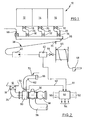
- zeigt äußerst schematisch eine Abgabevorrichtung nach der Erfindung.
- Fig. 2
- zeigt schematisch einen Teil der Abgabevorrichtung nach
Fig. 1 . - Fig. 3
- zeigt ein Rückschlagventil mit Sensor für die Abgabevorrichtung nach den
Figuren 1 und 2 .
- Fig. 1
- shows very schematically a dispensing device according to the invention.
- Fig. 2
- schematically shows a part of the dispenser after
Fig. 1 , - Fig. 3
- shows a check valve with sensor for the dispenser after the
Figures 1 and 2 ,
In
In
Im Leitungsabschnitt 24 zwischen Kollektorventil 30 und Bodenventil 18 ist ein Gehäuse 60 geflanscht, das in Verbindung steht mit einem nach oben gerichteten gekrümmten Rohrstutzen 62. Zwischen dem Rohrstutzen 62 und dem Gehäuse 60 ist ein Rückschlagventil 64 angeordnet. Am freien Ende weist der Rohrstutzen 62 einen Anschluss 66 auf, mit dem die Abgabepistole 48 verbunden werden kann. Dies ist im Einzelnen nicht dargestellt. Mit dem Rohrstutzen ist ein Druckluftanschluss 72 verbunden. Jeder Kammer 12 bis 16 ist ein Rohrstutzen 62 zugeordnet. In
Nach Beendigung des Abgabevorgangs kann das Produkt, das sich im Leitungsabschnitt 24, im Kollektor 36 und in der Abgabeleitung 38 sowie im Schlauch 46 befindet, in die Kammer 12 zurückgefördert werden. Zu diesem Zweck wird die Abgabepistole 48 mit dem Anschluss 66 dichtend verbunden. Anschließend wird das Bodenventil 18 geöffnet. Das Kollektorventil 30 ist geschlossen. Es wird nach Beendigung des Abgabevorgangs geschlossen. Anschließend wird die Pumpe 40 in Betrieb gesetzt und das Medium wird in die Kammer 12 zurückgepumpt.After completion of the dispensing operation, the product, which is in the
Die Rückführung des Mediums aus Kollektor und Abgabeleitung kann auf zwei verschiedene Weisen erfolgen. Im einen Fall wird der Kollektor 36 durch Schwerkraft bei laufender Pumpe geleert, wobei ein Lüftungsventil 68 die Entleerung zulässt. Die Entleerung erfolgt bis kurz vor der Pumpe 40, was etwa durch einen Leermeldesensor 70 angezeigt wird. Sein Signal wird auf die Steuervorrichtung 50 gegeben, welche die Pumpe 40 stoppt oder das Abgabeventil 44 schließt. Anschließend wird das Bodenventil einer weiteren Kammer, beispielsweise der Tankkammer 14 oder 16, mit dem Bodenventil 20 bzw. 22 geöffnet, sodass das noch im System befindliche "alte" Medium durch das "neue" Medium herausgedrückt und in die Tankkammer 12 rückgeführt wird. Über den Volumenzähler 42 und durch die bekannten Volumina im Abgabesystem kann festgestellt werden, wann das neue Medium an der Abgabepistole 48 angekommen ist. Eine andere Möglichkeit besteht darin, das "alte" Medium im gesamten Abgabesystem durch das "neue" Medium herauszudrücken. Auch hier kann über den Volumenzähler 42 festgestellt werden, wann das neue Medium an der Abgabepistole 48 angekommen ist. Im letzteren Fall ist die Produktvermischung größer als im ersteren Fall.The return of the medium from the collector and the discharge line can be done in two different ways. In one case, the
Nach Beendigung des beschriebenen Rückführvorgangs befindet sich noch Medium im Rohrstutzen 62. Dieses wird mit Hilfe der über den Anschluss 72 zugeführten Druckluft und bei geschlossener Abgabepistole 48 am Anschluss 46 über das Rückschlagventil 64 ebenfalls in die zugeordnete Kammer rückgedrückt. Danach wird die Abgabepistole vom Anschluss 66 entfernt und die Abgabe des neuen Mediums über die Abgabepistole 48 kann in der beschriebenen Art und Weise erfolgen.After completion of the described return operation is still medium in the
In
In der Steuervorrichtung 50 ist auch die Zuordnung der Anschlüsse 66 für die Rückführung zu den einzelnen Kammern 12 bis 16 registriert. Bei Auftauchen eines Überwachungssignals "weiß" die Steuervorrichtung, in welche Tankkammer eine Rückführung eines Mediums erfolgt. Dadurch besteht eine Überwachungsmöglichkeit der Rückführung in die zutreffende Kammer. Eine irrtümliche Rückführung in eine falsche Kammer wird sofort bemerkt und kann von der Steuervorrichtung 50 festgestellt werden, indem etwa die Pumpe 40 stillgesetzt oder das Abgabeventil 44 geschlossen wird. Auch eine manipulierte Rückführung in die unzutreffende Kammer zwecks späteren Entwendens des Mediums aus dieser Kammer kann auf diese Weise ebenfalls entweder registriert oder gestoppt werden.In the
Der Volumenzähler 42 zählt, wie erwähnt, auch das rückgeführte Volumen. Wird jedoch nach Beendigung dieses Vorgangs der Volumenzähler 42 nicht auf Null zurückgestellt und die Abgabepistole 48 an einen Kundentank angeschlossen, wird der Kunde um die Menge an Produkt betrogen, die vom Volumenzähler während der Rückführung des Produkts im Kreis registriert hat. Auch diese Manipulation kann daher durch die erfindungsgemäße Vorrichtung angezeigt oder durch sonstige Maßnahmen verhindert werden.The
Wie beschrieben, ist das Ventilglied 82 durch die Feder 84 gegen den Ventilsitz 74 vorgespannt. Wird zum Beispiel Druckluft dem Rohrstutzen 62 zugeführt, öffnet das Ventilglied 82 zwar um einen gewissen Betrag, um die Druckluft hindurchzulassen, der Öffnungsweg des Ventilglieds 82 ist jedoch signifikant geringer als der, den es beim Durchfließen von flüssigem Medium zurücklegt. Erst der letztere Weg wird vom Sensor 90 erfasst und zu einem Überwachungssignal gewandelt. Dadurch wird durch Druckluft eine verursachte Manipulation verhindert.As described, the
Claims (10)
- A device for dispensing liquid media from individual chambers of a tanker truck, wherein each of the chambers (12, 14, 16) is connected to a collector (36) through a floor valve (18, 20, 22) and a collector valve (30, 32, 34), and the collector (36) is connected via a discharge line (38) to a discharge hose (46) that has a discharge nozzle (48) at the end, wherein furthermore a pump (40) and a volume meter (42) are arranged in the discharge line (38), wherein in a line section (24, 26, 28) between the floor valve (18, 20, 22) and collector valve (30, 32, 34), there is a connection (66) for the discharge nozzle (48) which is connected via a check valve to the line section (24, 26, 28), characterized in that a sensor (90) is assigned to the connection before, after, or in the check valve and emits a monitoring signal to a control device (50) of the discharge device when a liquid medium flows through the connection.
- The device according to claim 1, characterized in that the control device (50) correlates the monitoring signal and the signal from the volume meter (42), and the control signal (50) generates a feedback signal when the signals have a predetermined correlation.
- The device according to claim 2, characterized in that the control device (50) monitors whether the first or last signal from the volume meter (42) and the monitoring signal appear within a predetermined time window, wherein the first signal corresponds to the start, and the last signal corresponds to the stop of the volume meter (42).
- The device according to one of claims 2 or 3, characterized in that the sensor (90) only responds when a specific stream of fluid flows through the connection at a predetermined pressure.
- The device according to one of claims 1 to 4, characterized in that the monitoring signals of the sensors are assigned to the chambers (12, 14, 16) or floor valves (18, 20, 22) in the control device (50), and the control device (50) thereby identifies the chamber (12, 14, 16) in which a fluid medium is returning.
- The device according to claim 5, characterized in that the control device (50) stops the return when the monitoring signal is not assigned to that chamber (12, 14, 16) from which the returned medium originates from the discharge line (38), or belongs to the chamber (12, 14, 16) to which the medium is to be returned.
- The device according to one of claims 3 to 6, characterized in that the control device (50) automatically resets the volume meter (42) to zero after returning ends.
- The device according to claim 7, characterized in that the connection for the discharge nozzle has a pipe sleeve (62) that is connected to a housing (60) which is arranged between the floor valve and collector valve along the line section (24).
- The device according to claim 8, characterized in that the sensor (90) is arranged in a wall of the housing (60) or pipe sleeve, and is assigned to a guide pushrod (86) of the check valve that is guided in a guide hole in the valve housing (78).
- The device according to one of claims 8 or 9, characterized in that the sensor (90) is a proximity sensor.
Priority Applications (1)
| Application Number | Priority Date | Filing Date | Title |
|---|---|---|---|
| PL10009365T PL2301800T3 (en) | 2009-09-21 | 2010-09-09 | Device for dispensing liquid media from individual chambers of a tanker |
Applications Claiming Priority (1)
| Application Number | Priority Date | Filing Date | Title |
|---|---|---|---|
| DE202009012992U DE202009012992U1 (en) | 2009-09-21 | 2009-09-21 | Device for dispensing liquid media from individual chambers of a tanker truck |
Publications (3)
| Publication Number | Publication Date |
|---|---|
| EP2301800A2 EP2301800A2 (en) | 2011-03-30 |
| EP2301800A3 EP2301800A3 (en) | 2013-03-06 |
| EP2301800B1 true EP2301800B1 (en) | 2014-12-24 |
Family
ID=42096789
Family Applications (1)
| Application Number | Title | Priority Date | Filing Date |
|---|---|---|---|
| EP10009365.7A Active EP2301800B1 (en) | 2009-09-21 | 2010-09-09 | Device for dispensing liquid media from individual chambers of a tanker |
Country Status (5)
| Country | Link |
|---|---|
| EP (1) | EP2301800B1 (en) |
| DE (1) | DE202009012992U1 (en) |
| DK (1) | DK2301800T3 (en) |
| ES (1) | ES2531756T3 (en) |
| PL (1) | PL2301800T3 (en) |
Families Citing this family (3)
| Publication number | Priority date | Publication date | Assignee | Title |
|---|---|---|---|---|
| DE102012010055A1 (en) * | 2012-03-20 | 2013-09-26 | HyPneu Service GmbH | Device and method for monitoring the tightness of compressed air-consuming or compressed air-carrying pneumatic elements |
| GB201416730D0 (en) * | 2014-09-22 | 2014-11-05 | Mechtronic Ltd | Fuel delivery apparatus and method |
| DE102016109436B4 (en) | 2016-05-23 | 2023-03-23 | Saeta Gmbh & Co. Kg | Installation and method for dispensing liquid from a tank truck |
Family Cites Families (2)
| Publication number | Priority date | Publication date | Assignee | Title |
|---|---|---|---|---|
| US3360000A (en) * | 1966-04-15 | 1967-12-26 | Gloster Saro Ltd | Discharging arrangements for bulk fluids |
| GB2321895B (en) | 1997-02-04 | 1999-01-27 | Maidment Tanker Services Limit | Product return system |
-
2009
- 2009-09-21 DE DE202009012992U patent/DE202009012992U1/en not_active Expired - Lifetime
-
2010
- 2010-09-09 ES ES10009365.7T patent/ES2531756T3/en active Active
- 2010-09-09 DK DK10009365T patent/DK2301800T3/en active
- 2010-09-09 PL PL10009365T patent/PL2301800T3/en unknown
- 2010-09-09 EP EP10009365.7A patent/EP2301800B1/en active Active
Also Published As
| Publication number | Publication date |
|---|---|
| ES2531756T3 (en) | 2015-03-18 |
| DK2301800T3 (en) | 2015-04-07 |
| EP2301800A2 (en) | 2011-03-30 |
| EP2301800A3 (en) | 2013-03-06 |
| PL2301800T3 (en) | 2015-05-29 |
| DE202009012992U1 (en) | 2010-04-08 |
Similar Documents
| Publication | Publication Date | Title |
|---|---|---|
| DE102006001866B4 (en) | Method and device for dispensing a fluid from a tank | |
| DE60005306T2 (en) | FUEL VAPOR RECOVERY SYSTEM TEST | |
| EP2202496B1 (en) | Piston-type dosing device with supervised valve | |
| DE102017123296B4 (en) | Fluid delivery assembly for removing gas bubbles from a fluid path | |
| EP2301800B1 (en) | Device for dispensing liquid media from individual chambers of a tanker | |
| EP1923349A1 (en) | Method for determining the gas return rate in petrol pumps | |
| EP1268341A1 (en) | Device and method for transporting a medium | |
| EP0895960A1 (en) | Process and device for dispensing liquid from a truck comprising multiple storage tanks | |
| EP3570902A1 (en) | Dialysate concentration measurement sensor diagnosis | |
| DE102017117568A1 (en) | Decontamination arrangement, system and decontamination process | |
| DE3228265C2 (en) | ||
| EP2633921B1 (en) | Painting system supplied by a single-piston pump | |
| DE69532920T2 (en) | Device for the volumetric delivery of liquids | |
| DE19963799A1 (en) | Liquid laboratory chemicals dosing station has programmable control unit for controlling delivery pump and dosing valve at delivery point | |
| EP0700865B1 (en) | Method and apparatus for monitoring and/or callibration of piston flowmeter in petrol stations | |
| EP2703788B1 (en) | Metering device and method for calibrating chambers of a tank | |
| DE102014010823B4 (en) | Method for operating a dosing system and dosing system | |
| DE102018218502B4 (en) | Method for detecting a faulty installation of a waste water pipe of a drinks machine | |
| DE10105545C1 (en) | Device for emptying fuel gauge in tanker wagons has lower emptying connection on gas measuring block connected through pump to collecting container and with upper discharge valve which shuts off during emptying | |
| EP3283234A1 (en) | Apparatus and method for the dosed dispensing of a liquid | |
| EP3861417A1 (en) | Liquid ejection device for a vehicle wash facility, and method for operating same | |
| DE4401808C1 (en) | Storage tank filling equipment | |
| EP3861416A1 (en) | Liquid ejection device for a vehicle wash facility, and method for operating same | |
| WO2022013194A1 (en) | Bioreactor cleaning installation for bioreactors in rail vehicles | |
| DE102017108884A1 (en) | metering |
Legal Events
| Date | Code | Title | Description |
|---|---|---|---|
| PUAI | Public reference made under article 153(3) epc to a published international application that has entered the european phase |
Free format text: ORIGINAL CODE: 0009012 |
|
| AK | Designated contracting states |
Kind code of ref document: A2 Designated state(s): AL AT BE BG CH CY CZ DE DK EE ES FI FR GB GR HR HU IE IS IT LI LT LU LV MC MK MT NL NO PL PT RO SE SI SK SM TR |
|
| AX | Request for extension of the european patent |
Extension state: BA ME RS |
|
| PUAL | Search report despatched |
Free format text: ORIGINAL CODE: 0009013 |
|
| AK | Designated contracting states |
Kind code of ref document: A3 Designated state(s): AL AT BE BG CH CY CZ DE DK EE ES FI FR GB GR HR HU IE IS IT LI LT LU LV MC MK MT NL NO PL PT RO SE SI SK SM TR |
|
| AX | Request for extension of the european patent |
Extension state: BA ME RS |
|
| RIC1 | Information provided on ipc code assigned before grant |
Ipc: B60P 3/22 20060101AFI20130125BHEP |
|
| 17P | Request for examination filed |
Effective date: 20130902 |
|
| RBV | Designated contracting states (corrected) |
Designated state(s): AL AT BE BG CH CY CZ DE DK EE ES FI FR GB GR HR HU IE IS IT LI LT LU LV MC MK MT NL NO PL PT RO SE SI SK SM TR |
|
| GRAP | Despatch of communication of intention to grant a patent |
Free format text: ORIGINAL CODE: EPIDOSNIGR1 |
|
| INTG | Intention to grant announced |
Effective date: 20140707 |
|
| GRAS | Grant fee paid |
Free format text: ORIGINAL CODE: EPIDOSNIGR3 |
|
| GRAA | (expected) grant |
Free format text: ORIGINAL CODE: 0009210 |
|
| AK | Designated contracting states |
Kind code of ref document: B1 Designated state(s): AL AT BE BG CH CY CZ DE DK EE ES FI FR GB GR HR HU IE IS IT LI LT LU LV MC MK MT NL NO PL PT RO SE SI SK SM TR |
|
| REG | Reference to a national code |
Ref country code: GB Ref legal event code: FG4D Free format text: NOT ENGLISH |
|
| REG | Reference to a national code |
Ref country code: CH Ref legal event code: EP |
|
| REG | Reference to a national code |
Ref country code: IE Ref legal event code: FG4D Free format text: LANGUAGE OF EP DOCUMENT: GERMAN |
|
| REG | Reference to a national code |
Ref country code: AT Ref legal event code: REF Ref document number: 702954 Country of ref document: AT Kind code of ref document: T Effective date: 20150115 |
|
| REG | Reference to a national code |
Ref country code: DE Ref legal event code: R096 Ref document number: 502010008546 Country of ref document: DE Effective date: 20150212 |
|
| REG | Reference to a national code |
Ref country code: ES Ref legal event code: FG2A Ref document number: 2531756 Country of ref document: ES Kind code of ref document: T3 Effective date: 20150318 |
|
| REG | Reference to a national code |
Ref country code: SE Ref legal event code: TRGR |
|
| REG | Reference to a national code |
Ref country code: DK Ref legal event code: T3 Effective date: 20150401 |
|
| REG | Reference to a national code |
Ref country code: NL Ref legal event code: VDEP Effective date: 20141224 |
|
| PG25 | Lapsed in a contracting state [announced via postgrant information from national office to epo] |
Ref country code: LT Free format text: LAPSE BECAUSE OF FAILURE TO SUBMIT A TRANSLATION OF THE DESCRIPTION OR TO PAY THE FEE WITHIN THE PRESCRIBED TIME-LIMIT Effective date: 20141224 Ref country code: FI Free format text: LAPSE BECAUSE OF FAILURE TO SUBMIT A TRANSLATION OF THE DESCRIPTION OR TO PAY THE FEE WITHIN THE PRESCRIBED TIME-LIMIT Effective date: 20141224 Ref country code: NO Free format text: LAPSE BECAUSE OF FAILURE TO SUBMIT A TRANSLATION OF THE DESCRIPTION OR TO PAY THE FEE WITHIN THE PRESCRIBED TIME-LIMIT Effective date: 20150324 |
|
| REG | Reference to a national code |
Ref country code: LT Ref legal event code: MG4D |
|
| PG25 | Lapsed in a contracting state [announced via postgrant information from national office to epo] |
Ref country code: GR Free format text: LAPSE BECAUSE OF FAILURE TO SUBMIT A TRANSLATION OF THE DESCRIPTION OR TO PAY THE FEE WITHIN THE PRESCRIBED TIME-LIMIT Effective date: 20150325 Ref country code: LV Free format text: LAPSE BECAUSE OF FAILURE TO SUBMIT A TRANSLATION OF THE DESCRIPTION OR TO PAY THE FEE WITHIN THE PRESCRIBED TIME-LIMIT Effective date: 20141224 Ref country code: HR Free format text: LAPSE BECAUSE OF FAILURE TO SUBMIT A TRANSLATION OF THE DESCRIPTION OR TO PAY THE FEE WITHIN THE PRESCRIBED TIME-LIMIT Effective date: 20141224 |
|
| REG | Reference to a national code |
Ref country code: PL Ref legal event code: T3 |
|
| PG25 | Lapsed in a contracting state [announced via postgrant information from national office to epo] |
Ref country code: NL Free format text: LAPSE BECAUSE OF FAILURE TO SUBMIT A TRANSLATION OF THE DESCRIPTION OR TO PAY THE FEE WITHIN THE PRESCRIBED TIME-LIMIT Effective date: 20141224 |
|
| PG25 | Lapsed in a contracting state [announced via postgrant information from national office to epo] |
Ref country code: RO Free format text: LAPSE BECAUSE OF FAILURE TO SUBMIT A TRANSLATION OF THE DESCRIPTION OR TO PAY THE FEE WITHIN THE PRESCRIBED TIME-LIMIT Effective date: 20141224 Ref country code: EE Free format text: LAPSE BECAUSE OF FAILURE TO SUBMIT A TRANSLATION OF THE DESCRIPTION OR TO PAY THE FEE WITHIN THE PRESCRIBED TIME-LIMIT Effective date: 20141224 Ref country code: SK Free format text: LAPSE BECAUSE OF FAILURE TO SUBMIT A TRANSLATION OF THE DESCRIPTION OR TO PAY THE FEE WITHIN THE PRESCRIBED TIME-LIMIT Effective date: 20141224 |
|
| PG25 | Lapsed in a contracting state [announced via postgrant information from national office to epo] |
Ref country code: IS Free format text: LAPSE BECAUSE OF FAILURE TO SUBMIT A TRANSLATION OF THE DESCRIPTION OR TO PAY THE FEE WITHIN THE PRESCRIBED TIME-LIMIT Effective date: 20150424 |
|
| REG | Reference to a national code |
Ref country code: DE Ref legal event code: R097 Ref document number: 502010008546 Country of ref document: DE |
|
| REG | Reference to a national code |
Ref country code: HU Ref legal event code: AG4A Ref document number: E023917 Country of ref document: HU |
|
| PLBE | No opposition filed within time limit |
Free format text: ORIGINAL CODE: 0009261 |
|
| STAA | Information on the status of an ep patent application or granted ep patent |
Free format text: STATUS: NO OPPOSITION FILED WITHIN TIME LIMIT |
|
| 26N | No opposition filed |
Effective date: 20150925 |
|
| PG25 | Lapsed in a contracting state [announced via postgrant information from national office to epo] |
Ref country code: SI Free format text: LAPSE BECAUSE OF FAILURE TO SUBMIT A TRANSLATION OF THE DESCRIPTION OR TO PAY THE FEE WITHIN THE PRESCRIBED TIME-LIMIT Effective date: 20141224 |
|
| REG | Reference to a national code |
Ref country code: DE Ref legal event code: R119 Ref document number: 502010008546 Country of ref document: DE |
|
| PG25 | Lapsed in a contracting state [announced via postgrant information from national office to epo] |
Ref country code: LU Free format text: LAPSE BECAUSE OF FAILURE TO SUBMIT A TRANSLATION OF THE DESCRIPTION OR TO PAY THE FEE WITHIN THE PRESCRIBED TIME-LIMIT Effective date: 20150909 Ref country code: MC Free format text: LAPSE BECAUSE OF FAILURE TO SUBMIT A TRANSLATION OF THE DESCRIPTION OR TO PAY THE FEE WITHIN THE PRESCRIBED TIME-LIMIT Effective date: 20141224 |
|
| REG | Reference to a national code |
Ref country code: CH Ref legal event code: PL |
|
| REG | Reference to a national code |
Ref country code: IE Ref legal event code: MM4A |
|
| PG25 | Lapsed in a contracting state [announced via postgrant information from national office to epo] |
Ref country code: CH Free format text: LAPSE BECAUSE OF NON-PAYMENT OF DUE FEES Effective date: 20150930 Ref country code: IE Free format text: LAPSE BECAUSE OF NON-PAYMENT OF DUE FEES Effective date: 20150909 Ref country code: DE Free format text: LAPSE BECAUSE OF NON-PAYMENT OF DUE FEES Effective date: 20160401 Ref country code: LI Free format text: LAPSE BECAUSE OF NON-PAYMENT OF DUE FEES Effective date: 20150930 |
|
| REG | Reference to a national code |
Ref country code: FR Ref legal event code: PLFP Year of fee payment: 7 |
|
| PG25 | Lapsed in a contracting state [announced via postgrant information from national office to epo] |
Ref country code: MT Free format text: LAPSE BECAUSE OF FAILURE TO SUBMIT A TRANSLATION OF THE DESCRIPTION OR TO PAY THE FEE WITHIN THE PRESCRIBED TIME-LIMIT Effective date: 20141224 |
|
| PG25 | Lapsed in a contracting state [announced via postgrant information from national office to epo] |
Ref country code: SM Free format text: LAPSE BECAUSE OF FAILURE TO SUBMIT A TRANSLATION OF THE DESCRIPTION OR TO PAY THE FEE WITHIN THE PRESCRIBED TIME-LIMIT Effective date: 20141224 Ref country code: BG Free format text: LAPSE BECAUSE OF FAILURE TO SUBMIT A TRANSLATION OF THE DESCRIPTION OR TO PAY THE FEE WITHIN THE PRESCRIBED TIME-LIMIT Effective date: 20141224 |
|
| PG25 | Lapsed in a contracting state [announced via postgrant information from national office to epo] |
Ref country code: CY Free format text: LAPSE BECAUSE OF FAILURE TO SUBMIT A TRANSLATION OF THE DESCRIPTION OR TO PAY THE FEE WITHIN THE PRESCRIBED TIME-LIMIT Effective date: 20141224 |
|
| PG25 | Lapsed in a contracting state [announced via postgrant information from national office to epo] |
Ref country code: TR Free format text: LAPSE BECAUSE OF FAILURE TO SUBMIT A TRANSLATION OF THE DESCRIPTION OR TO PAY THE FEE WITHIN THE PRESCRIBED TIME-LIMIT Effective date: 20141224 |
|
| REG | Reference to a national code |
Ref country code: FR Ref legal event code: PLFP Year of fee payment: 8 |
|
| PG25 | Lapsed in a contracting state [announced via postgrant information from national office to epo] |
Ref country code: MK Free format text: LAPSE BECAUSE OF FAILURE TO SUBMIT A TRANSLATION OF THE DESCRIPTION OR TO PAY THE FEE WITHIN THE PRESCRIBED TIME-LIMIT Effective date: 20141224 |
|
| PG25 | Lapsed in a contracting state [announced via postgrant information from national office to epo] |
Ref country code: PT Free format text: LAPSE BECAUSE OF FAILURE TO SUBMIT A TRANSLATION OF THE DESCRIPTION OR TO PAY THE FEE WITHIN THE PRESCRIBED TIME-LIMIT Effective date: 20141224 |
|
| REG | Reference to a national code |
Ref country code: FR Ref legal event code: PLFP Year of fee payment: 9 |
|
| PG25 | Lapsed in a contracting state [announced via postgrant information from national office to epo] |
Ref country code: AL Free format text: LAPSE BECAUSE OF FAILURE TO SUBMIT A TRANSLATION OF THE DESCRIPTION OR TO PAY THE FEE WITHIN THE PRESCRIBED TIME-LIMIT Effective date: 20141224 |
|
| PGFP | Annual fee paid to national office [announced via postgrant information from national office to epo] |
Ref country code: GB Payment date: 20230921 Year of fee payment: 14 Ref country code: CZ Payment date: 20230828 Year of fee payment: 14 Ref country code: AT Payment date: 20230915 Year of fee payment: 14 |
|
| PGFP | Annual fee paid to national office [announced via postgrant information from national office to epo] |
Ref country code: SE Payment date: 20230921 Year of fee payment: 14 Ref country code: PL Payment date: 20230825 Year of fee payment: 14 Ref country code: HU Payment date: 20230901 Year of fee payment: 14 Ref country code: FR Payment date: 20230918 Year of fee payment: 14 Ref country code: DK Payment date: 20230921 Year of fee payment: 14 Ref country code: BE Payment date: 20230918 Year of fee payment: 14 |
|
| PGFP | Annual fee paid to national office [announced via postgrant information from national office to epo] |
Ref country code: ES Payment date: 20231019 Year of fee payment: 14 |
|
| PGFP | Annual fee paid to national office [announced via postgrant information from national office to epo] |
Ref country code: IT Payment date: 20230929 Year of fee payment: 14 |