EP2202496B1 - Piston-type dosing device with supervised valve - Google Patents
Piston-type dosing device with supervised valve Download PDFInfo
- Publication number
- EP2202496B1 EP2202496B1 EP09180057.3A EP09180057A EP2202496B1 EP 2202496 B1 EP2202496 B1 EP 2202496B1 EP 09180057 A EP09180057 A EP 09180057A EP 2202496 B1 EP2202496 B1 EP 2202496B1
- Authority
- EP
- European Patent Office
- Prior art keywords
- piston
- piston rod
- dosing
- closing
- membrane
- Prior art date
- Legal status (The legal status is an assumption and is not a legal conclusion. Google has not performed a legal analysis and makes no representation as to the accuracy of the status listed.)
- Active
Links
- 239000012528 membrane Substances 0.000 claims description 50
- 238000000034 method Methods 0.000 claims description 18
- 239000000463 material Substances 0.000 claims description 15
- 238000012544 monitoring process Methods 0.000 claims description 11
- 238000001514 detection method Methods 0.000 claims description 8
- 238000005429 filling process Methods 0.000 claims description 3
- 238000003860 storage Methods 0.000 claims description 2
- 238000003825 pressing Methods 0.000 description 8
- 239000000853 adhesive Substances 0.000 description 2
- 230000001070 adhesive effect Effects 0.000 description 2
- TZCXTZWJZNENPQ-UHFFFAOYSA-L barium sulfate Chemical compound [Ba+2].[O-]S([O-])(=O)=O TZCXTZWJZNENPQ-UHFFFAOYSA-L 0.000 description 2
- 239000011230 binding agent Substances 0.000 description 2
- 239000004848 polyfunctional curative Substances 0.000 description 2
- 238000011144 upstream manufacturing Methods 0.000 description 2
- 240000003517 Elaeocarpus dentatus Species 0.000 description 1
- 241001295925 Gegenes Species 0.000 description 1
- 238000005299 abrasion Methods 0.000 description 1
- 238000013459 approach Methods 0.000 description 1
- 238000004891 communication Methods 0.000 description 1
- 230000002950 deficient Effects 0.000 description 1
- 230000001419 dependent effect Effects 0.000 description 1
- 238000013461 design Methods 0.000 description 1
- 239000007788 liquid Substances 0.000 description 1
- 238000012423 maintenance Methods 0.000 description 1
- 238000004519 manufacturing process Methods 0.000 description 1
- 239000002245 particle Substances 0.000 description 1
- 235000011837 pasties Nutrition 0.000 description 1
- 238000007789 sealing Methods 0.000 description 1
- 239000007779 soft material Substances 0.000 description 1
- 210000002023 somite Anatomy 0.000 description 1
- 230000003068 static effect Effects 0.000 description 1
- 230000001360 synchronised effect Effects 0.000 description 1
Images


Classifications
-
- G—PHYSICS
- G01—MEASURING; TESTING
- G01F—MEASURING VOLUME, VOLUME FLOW, MASS FLOW OR LIQUID LEVEL; METERING BY VOLUME
- G01F11/00—Apparatus requiring external operation adapted at each repeated and identical operation to measure and separate a predetermined volume of fluid or fluent solid material from a supply or container, without regard to weight, and to deliver it
- G01F11/02—Apparatus requiring external operation adapted at each repeated and identical operation to measure and separate a predetermined volume of fluid or fluent solid material from a supply or container, without regard to weight, and to deliver it with measuring chambers which expand or contract during measurement
- G01F11/021—Apparatus requiring external operation adapted at each repeated and identical operation to measure and separate a predetermined volume of fluid or fluent solid material from a supply or container, without regard to weight, and to deliver it with measuring chambers which expand or contract during measurement of the piston type
-
- F—MECHANICAL ENGINEERING; LIGHTING; HEATING; WEAPONS; BLASTING
- F16—ENGINEERING ELEMENTS AND UNITS; GENERAL MEASURES FOR PRODUCING AND MAINTAINING EFFECTIVE FUNCTIONING OF MACHINES OR INSTALLATIONS; THERMAL INSULATION IN GENERAL
- F16K—VALVES; TAPS; COCKS; ACTUATING-FLOATS; DEVICES FOR VENTING OR AERATING
- F16K37/00—Special means in or on valves or other cut-off apparatus for indicating or recording operation thereof, or for enabling an alarm to be given
- F16K37/0025—Electrical or magnetic means
- F16K37/0041—Electrical or magnetic means for measuring valve parameters
-
- F—MECHANICAL ENGINEERING; LIGHTING; HEATING; WEAPONS; BLASTING
- F16—ENGINEERING ELEMENTS AND UNITS; GENERAL MEASURES FOR PRODUCING AND MAINTAINING EFFECTIVE FUNCTIONING OF MACHINES OR INSTALLATIONS; THERMAL INSULATION IN GENERAL
- F16K—VALVES; TAPS; COCKS; ACTUATING-FLOATS; DEVICES FOR VENTING OR AERATING
- F16K7/00—Diaphragm valves or cut-off apparatus, e.g. with a member deformed, but not moved bodily, to close the passage ; Pinch valves
- F16K7/12—Diaphragm valves or cut-off apparatus, e.g. with a member deformed, but not moved bodily, to close the passage ; Pinch valves with flat, dished, or bowl-shaped diaphragm
- F16K7/14—Diaphragm valves or cut-off apparatus, e.g. with a member deformed, but not moved bodily, to close the passage ; Pinch valves with flat, dished, or bowl-shaped diaphragm arranged to be deformed against a flat seat
- F16K7/17—Diaphragm valves or cut-off apparatus, e.g. with a member deformed, but not moved bodily, to close the passage ; Pinch valves with flat, dished, or bowl-shaped diaphragm arranged to be deformed against a flat seat the diaphragm being actuated by fluid pressure
-
- G—PHYSICS
- G01—MEASURING; TESTING
- G01F—MEASURING VOLUME, VOLUME FLOW, MASS FLOW OR LIQUID LEVEL; METERING BY VOLUME
- G01F15/00—Details of, or accessories for, apparatus of groups G01F1/00 - G01F13/00 insofar as such details or appliances are not adapted to particular types of such apparatus
- G01F15/005—Valves
Definitions
- the invention relates to piston dispensers with monitored valves, in particular inlet valves, and a method for monitoring the piston dispenser.
- the respective, mostly pasty, component is drawn up by retracting the metering piston via a connected inlet line from a storage container in a metering cylinder, which receives the desired dosing with retracted dosing, or flowed into the metering cylinder due to the overpressure in the reservoir and the dosing cylinder filled , Subsequently, the dosing amount contained in the dosing cylinder is fed and dosed out by pushing the dosing piston forward via an outlet line of the desired outlet opening, usually a nozzle or an upstream mixing tube. This is usually done simultaneously for two dosing cylinders next to each other for e.g. Binder and hardener of a two-component adhesive.
- an inlet valve in each inlet line and an outlet valve are installed in each outlet line in order to keep the outlet line closed during filling of the dosing cylinder and to keep the inlet line closed when dosing out to the outlet opening.
- the inlet and outlet valves are often designed as diaphragm valves, in which the component to be metered is located only on one side of the membrane, which can be pressed from the other side of the membrane by means of a lock cylinder against a pressing surface to the flow through the valve for the respective component.
- Another sometimes occurring source of error may be the tearing of the membrane, which is subject to relatively rapid wear, especially when dosing components containing abrasive particles, and a crack or even a leak due to no longer being smooth if the wear is not noticed in time. directed against the pressing surface, the surface of the membrane may be the result.
- Another source of error sometimes occurring may be that air from the reservoir with the material to be metered into one or more dosing, which is too low when emptying the metered amount because of the introduced air.
- the change interval of the membrane was first set very short, and tested the first change the state of wear of the membrane and then, if possible, the length of the change interval gradually increased to an acceptable level, without Risk of tearing the membrane due to wear.
- the diaphragm valves in particular the inlet valve, have not been monitored for their function, in particular not by monitoring the position of the closing piston.
- a reciprocating pump for conveying liquid is known, which is connected to the delivery line only via a single branch line and downstream and upstream of the mouth of the stub in a delivery line in each case has a check valve whose wear condition is to be detected by sound pickup on these valves.
- the wear of a valve adjusting device should be determined by deactivating the actuating device for the corresponding valve and then reactivating it and comparing the distances traveled by the actuating element with the path lengths covered in the original state of the valve. Deviations indicate wear on the actuator and / or valve.
- a monitoring of the piston position is particularly useful in the design of a diaphragm valve, since the membrane functionally must consist of a relatively soft material. Nevertheless, such a monitoring also makes sense in poppet valves or slide valves, in which relatively hard sealing surfaces are pressed against each other. Also, there is wear and leads to leaks.
- the predetermined setpoint values of the respective positions ie open position and / or closed position
- a corresponding position sensor which is arranged on the closing element, for example the closing piston
- the determination of the state of wear and timely replacement for example, the closing membrane or the other responsible closing element, eg the valve body of a poppet valve, has the goal.
- the change in the actual position of the closing piston in the closed position of the inlet valve is determined from the beginning either at each stroke or at certain time or numerical intervals, and as soon as the change in this actual position reaches a predetermined level, e.g. If the permissible thickness wear path of the closing membrane is reached or exceeded, a change instruction is issued to the operator for the closing membrane.
- the wear value e.g. the thickness-wear of the closing membrane
- parameters such as pneumatic pressure on the valve, temperature of the material to be dosed and / or dosing
- parameters of the material of the membrane one or more of these parameters can be additionally measured and determined by the controller for the determination the permissible thickness wear value are taken into account.
- the closing membrane is softer and more elastic due to the high temperature, and can be compressed more strongly at the same closing pressure, so that then the thickness-wear value must be set higher with increasing temperature.
- the actual values for both the rough detection and for the enemy detection are preferably carried out with the same single position sensor per valve.
- the piston rod which moves the dosing piston and / or the dosing piston itself is also completely retracted, especially with regard to reaching it Position detected, preferably using a position sensor of the same type as it is used to monitor the valves.
- the metering piston does not have to be actively withdrawn during filling, but is forced back due to the medium flowing into the metering cylinder with overpressure.
- the piston rod drive can still be in contact with the piston rod and thus the metering piston in order to provide a stop in the fully retracted position of the metering piston, ie the fully filled position of the metering cylinder with the desired metering volume.
- the piston rod drive from Dosing be solved - regardless of whether at the junction between the piston rod drive and piston rod or between the piston rod and metering - and be detected whether then the metering still moves backwards. This would only be the case if in the metering cylinder gas, so undesirable sucked or pressed air, was present and was compressed by the press-fitting and now pushes after removal of the piston rod drive and its counterforce from the metering further to the rear.
- Additional movement of the metering piston after reaching the regular retracted end position can thus detect air contained in the metering cylinder by a further sensor after disconnecting the piston rod drive.
- the fully advanced position of the piston rod and the metering piston is monitored analogously, as well as the incomplete extension can also be a reason for too low dosing volume.
- the piston dispenser according to the invention has inlet and outlet valves in the form of diaphragm valves, the closing membrane is acted upon on the side facing away from the medium to be conveyed by a closing piston, which in turn is moved in the axial direction by means of compressed air, preferably by in turn on the back of the Closing a second diaphragm, the control diaphragm, is arranged.
- the compressed air is then on the side facing away from the closing piston side of the control diaphragm.
- each valve to be monitored is a position sensor as well as at each of the piston rods to be monitored.
- All sensors are linked to a central monitoring control.
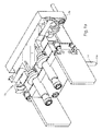
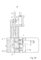
- the Figures 3 show one of the two piston dispensers for dosing a single component in the different phases of movement.
- two or even more metering pistons are provided side by side for metering a plurality of components to be mixed together, such as binders and hardeners of an adhesive, e.g. B. by a common drive with synchronous movements of their piston rods can be driven together.
- FIG. 3 shows, opens in the metering cylinder 3, in the lower end face, on the one hand, an inlet line 5, via which the component to be metered is supplied to the metering cylinder 3, and an outlet line 6, via which the defined metering volume contained therein after filling the metering cylinder 3 Component is ejected in the direction of the outlet opening, which - if two or more components are to be mixed - in a mixer, for example in a static mixing tube 14, opens, at the outlet opening 14a then the two components leaked sufficiently mixed.
- the inlet valve 15 In the inlet line 5, the inlet valve 15 is shown, together with the valve acting on this and controlling the pneumatic cylinder, and in de Outlet line 6, the outlet valve 16, which is generally constructed analogously to the inlet valve 15 and is also acted upon by a pneumatic cylinder.
- the entire dosing volume contained therein is squeezed out via the outlet 6. Since the outlet 6 to the actual outlet opening 14 a, approximately the front end of the mixing tube 14 according to FIG. 1a is constantly filled, occurs at each stroke from the outlet opening 14a, the dosing volume or the sum of the dosing volume of the two or more coupled dosing.
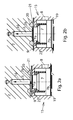
- FIGS. 1a and 1b show a section through the two inlet lines 5, which from the reservoirs 17a, b from the respective component via a in this inlet line 5 each arranged inlet valve 15 to the respective piston dispenser 1, that is, the metering cylinder 3, perform.
- the inlet valves 15 are each designed as diaphragm valves, one of which increases in FIG. 2a in the open position and in FIG. 2b is shown in the closed position.
- annular channel 20 is formed as a recessed groove in an end face of the housing 2, which - as best FIG. 1b shows - via the supply line 5 'with the respective reservoir 17a, b is in communication.
- the inlet line 5 which connects the inlet valve 15 with the respective metering piston 1 opens.
- the annular channel 20 and thus also the mouth of the inlet line 5 are located in a circular depression 21 of the end face of the base body 2, which extends at least to the radially outer edge of the annular channel 20.
- the lowering 21 is spanned by a flexible closing membrane 9, which bears tightly against the non-lowered surrounding area of the end face of the main body 2 and, in the unloaded state, according to the open position FIG. 2a , a sufficient axial distance between the closing membrane 9 and the bottom of the reduction 21 leaves free according to the depth of the reduction 21, that from the annular channel 20, the component to be metered in the flow direction 10 through this distance into the inlet line 5 and from there into the metering cylinder 3 with sufficient filling speed can flow.
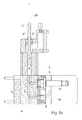
- a closing piston 7 On the rear side of the closing membrane 9, opposite the mouth of the inlet line 5, there is a closing piston 7, which has a flat front end face whose diameter is greater than the diameter of the mouth of the inlet line 5, namely as large as the circular pressing face located inside the annular channel 20 which also forms a flat surface.
- the closing piston 7 is axially, ie in the direction of the pressing surface and away from this, movable and is in its retracted position, the open position of this inlet valve 15, the closing piston 7 does not act on the closing membrane 9 in the direction of the pressing surface 2a, and in this retracted position of the closing piston 7 is biased by a coil spring 22 which is supported on the one hand on the housing 2 and on the other hand on a corresponding shoulder of the closing piston 7.
- the closing piston 7 is moved axially forward in the direction of pressing surface 2a until it presses the flexible closing membrane 9 against the pressing surface 2 and thereby closes the passage from the annular channel 20 to the inlet line 5.
- the closing piston 7 is pneumatically moved in this case by a control diaphragm 19 abuts on the rear end face 7b of the closing piston 7, which is acted upon on its rear side facing away from the closing piston 7 by means of compressed air and the locking piston 7 axially pressed forward with a force accordingly the applied pneumatic pressure to the system of the closing membrane 9 on the pressing surface 2a.
- the axial position of the closing piston 7 is now detected by means of a position sensor 8 at least in its closed position, preferably also detected in its open position or best of all the movement path of the closing piston.
- the position sensor 8 is located radially outside of the closing piston 7 in the housing 2 and is directed radially against the closing piston to preferably a shoulder or marking present there Feel contactless, the operating principle of the position sensor 8 is arbitrary. However, the position sensor 8 could just as well be directed in the axial direction against a corresponding shoulder of the closing piston 7.
- the bias of the coil spring 7, etc. - also depends on the thickness and elasticity of the closing membrane 9, the axial closed position of the closing piston 7 changes with increasing wear of the closing membrane 9, the is subject to abrasion due to the medium constantly flowing along it.
- Possibly. can be used for detecting the open and closed position of the closing piston 7 and separate position sensors.
- a tearing of the closing membrane 9 can be monitored by a moisture sensor 23 is positioned on the medium to be dosed, ie on the side of the closing piston 7, close to the closing membrane 9, approximately on the housing 2, which then abuts when due a cracked closing membrane 9 passes the moist medium to be dosed on the back of the closing membrane 9.
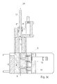
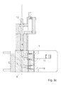
- Fig. 3 shows, in addition, that in addition the axial position of the metering piston 4 can be detected by a further position sensor 8 'in order to detect, above all, the correct fully retracted position of the metering piston 4, from which the metering volume correctly absorbed in the metering cylinder 3 depends:
- the position of the rear end of the metering piston 4 is detected in its rear retracted position by means of the second position sensor 8 '.
- metering piston 4 and piston rod 12 are integral or a play-free connected unit, instead of the position of the metering piston 4, the position of the piston rod 12 can be detected, for example by means of a mark attached thereto.
- the additional position sensor 8 is arranged somewhat further forward than the sensor 8. If the medium to be dispensed were to be pressed into the metering cylinder 3 during filling of the metering cylinder 3 and the metering piston 4 would thereby be pushed back, the additional position sensor would have to be pushed 8 "opposite the position sensor 8 'placed a little further back.
Description
Die Erfindung betrifft Kolbendosierer mit überwachten Ventilen, insbesondere Einlassventilen, sowie ein Verfahren zum Überwachen des Kolbendosierers.The invention relates to piston dispensers with monitored valves, in particular inlet valves, and a method for monitoring the piston dispenser.
Bei Kolbendosierern wird in einem Dosierzylinder, der bei zurückgezogenem Dosierkolben die gewünschte Dosiermenge aufnimmt, die jeweilige, meist pastöse, Komponente durch Zurückziehen des Dosierkolbens über eine angeschlossene Einlassleitung aus einem Vorratsbehälter aufgezogen oder auf Grund des Überdruckes im Vorratsbehälter in den Dosierzylinder eingeströmt und der Dosierzylinder gefüllt. Anschließend wird die im Dosierzylinder enthaltene Dosiermenge durch Vorwärtsschieben des Dosierkolbens über eine Auslassleitung der gewünschten Auslassöffnung, meist einer Düse oder einem vorgeschalteten Mischrohr, zugeführt und ausdosiert. Dies erfolgt meist für zwei Dosierzylinder gleichzeitig nebeneinander für z.B. Binder und Härter eines Zweikomponentenklebers.In piston dispensers, the respective, mostly pasty, component is drawn up by retracting the metering piston via a connected inlet line from a storage container in a metering cylinder, which receives the desired dosing with retracted dosing, or flowed into the metering cylinder due to the overpressure in the reservoir and the dosing cylinder filled , Subsequently, the dosing amount contained in the dosing cylinder is fed and dosed out by pushing the dosing piston forward via an outlet line of the desired outlet opening, usually a nozzle or an upstream mixing tube. This is usually done simultaneously for two dosing cylinders next to each other for e.g. Binder and hardener of a two-component adhesive.
Hierfür ist in jeder Einlassleitung ein Einlassventil und in jeder Auslassleitung ein Auslassventil, in der Regel I/O-Ventile, eingebaut, um beim Befüllen des Dosierzylinders die Auslassleitung geschlossen zu halten und beim Ausdosieren zur Auslassöffnung hin die Einlassleitung geschlossen zu halten.For this purpose, an inlet valve in each inlet line and an outlet valve, usually I / O valves, are installed in each outlet line in order to keep the outlet line closed during filling of the dosing cylinder and to keep the inlet line closed when dosing out to the outlet opening.
Die Ein- und Auslassventile sind häufig als Membranventile ausgebildet, bei der die zu dosierende Komponente sich nur auf einer Seite der Membran befindet, die von der anderen Seite der Membrane aus mittels eines Schließzylinders gegen eine Pressfläche gepresst werden kann, um den Durchfluss durch das Ventil für die jeweilige Komponente zu sperren.The inlet and outlet valves are often designed as diaphragm valves, in which the component to be metered is located only on one side of the membrane, which can be pressed from the other side of the membrane by means of a lock cylinder against a pressing surface to the flow through the valve for the respective component.
Um die Prozesssicherheit zu erhöhen, werden umfangreiche Anstrengungen unternommen, um Fehler beim Einsatz des Kolbendosierers zu vermeiden bzw. aufgetretene Fehler so schnell wie möglich zu erkennen und ihre Ursache bestimmen zu können.In order to increase the process reliability, extensive efforts are made to avoid mistakes in the use of the piston dispenser or to detect any errors as quickly as possible and to be able to determine their cause.
So kann das Dosierergebnis zu ungenau sein, also die dosierte Menge zu gering sein, indem überhöhte Arbeitsdrücke im Dosierer auftreten. Der Grund hierfür könnte sein, dass
- ein zu dünnes Mischrohr bzw. eine zu dünne Dosiernadel bei Einkomponentendosierern montiert ist,
- im Auslassbereich des Dosierers Bohrungen verstopft sind aufgrund unzureichender oder falscher Wartungsarbeiten,
- sich im Mischrohr bereits zu sehr ausgehärtetes Material befindet,
- die Dosiergeschwindigkeit, also der Füll- und Entleervorgang des Dosierzylinders, zu schnell durchgeführt wird, oder
- der Materialeingangsdruck beim Befüllen der Dosiereinrichtung zu hoch ist.
- a too thin mixing tube or a too thin dispensing needle is mounted in one-component dispensers,
- holes are blocked in the outlet area of the dosing unit due to insufficient or incorrect maintenance work,
- If there is already too much hardened material in the mixing tube,
- the dosing, ie the filling and emptying of the dosing, is carried out too quickly, or
- the material input pressure when filling the metering device is too high.
Eine weitere manchmal auftretende Fehlerquelle kann das Reißen der Membran sein, die vor allem beim Dosieren von Komponenten, die abrasive Partikel enthalten, einer relativ schnellen Abnutzung unterliegen und bei nicht rechtzeitigem Bemerken einer zu starken Abnutzung ein Riss oder auch eine Undichtigkeit aufgrund nicht mehr glatter, gegen die Pressfläche gerichteter, Oberfläche der Membran die Folge sein kann.Another sometimes occurring source of error may be the tearing of the membrane, which is subject to relatively rapid wear, especially when dosing components containing abrasive particles, and a crack or even a leak due to no longer being smooth if the wear is not noticed in time. directed against the pressing surface, the surface of the membrane may be the result.
Eine weitere manchmal auftretende Fehlerquelle kann sein, dass Luft aus dem Vorratsbehälter mit dem zu dosierenden Material in einen oder mehrere Dosierzylinder gelangt, wodurch beim Entleeren die dosierte Menge wegen der eingebrachten Luft zu gering ist.Another source of error sometimes occurring may be that air from the reservoir with the material to be metered into one or more dosing, which is too low when emptying the metered amount because of the introduced air.
Bisher wurde zur Überwachung des Membranverschleißes bei Inbetriebnahme einer Anlage mit einer neuen zu fördernden Komponente der Wechselintervall der Membran zunächst sehr kurz festgelegt, und beim ersten Wechseln der Verschleißzustand der Membran geprüft und anschließend nach Möglichkeit die Länge des Wechselintervalls schrittweise auf ein vertretbares Maß vergrößert, ohne ein Reißen der Membran durch Verschleiß zu riskieren.So far, to monitor the membrane wear when commissioning a system with a new component to be conveyed, the change interval of the membrane was first set very short, and tested the first change the state of wear of the membrane and then, if possible, the length of the change interval gradually increased to an acceptable level, without Risk of tearing the membrane due to wear.
Die Membranventile, insbesondere das Einlassventil, wurden dagegen nicht auf ihre Funktion überwacht, insbesondere nicht durch Überwachung der Position des Schließkolbens.By contrast, the diaphragm valves, in particular the inlet valve, have not been monitored for their function, in particular not by monitoring the position of the closing piston.
Wenn somit beim Ausdosieren des Materials durch die Auslassleitung das Einlassventil nicht vollständig korrekt geschlossen war - beispielsweise weil ein zu hoher Widerstand im Auspressweg vorhanden war oder der Arbeitsdruck in der Einlassleitung vom Vorratsbehälter her unzulässig hoch war oder ähnliches - wird ein Teil des Materials aus dem Dosierzylinder nicht über die Auslassleitung wie gewünscht zur Auslassöffnung gepresst, sondern durch das teilweise oder ganz offene Einlassventil zurück in den Vorratsbehälter, und das ausdosierte Volumen ist zu gering.Thus, if the inlet valve was not fully closed properly during metering out of the material through the outlet line - for example, because there was too much resistance in the discharge path, or the working pressure in the inlet line from the reservoir was prohibitively high or the like - some of the material would be out of the metering cylinder is not forced through the outlet as desired to the outlet, but through the partially or completely open inlet valve back into the reservoir, and the metered volume is too low.
Das gleiche tritt natürlich auf, wenn der Dosierzylinder gar nicht vollständig mit Material gefüllt war, bevor das Ausdosieren begann, beispielsweise weil der Dosierkolben nicht vollständig oder zu schnell in die zurückgezogene Position gefahren wurde.The same occurs, of course, when the dosing cylinder was not completely filled with material before dosing began, for example because the dosing piston was not driven fully or too quickly to the retracted position.
Aus der
Aus der
Auf Seite 7 erwähnt diese Schrift auch einen Stellungsgeber, um den Ventilzustand zu ermitteln, jedoch ist weder gesagt, wo dieser angeordnet sein soll, welches Teil des Ventils hinsichtlich seiner Position überwacht werden soll und welche Stellung dieses Elementes überwacht werden soll. Vor allem aber stellt diese Schrift selbst einen solchen Positionsgeber als unsinnig dar, da der Verschleißzustand bereits aufgrund der Schallanalyse bekannt sei.On
Aus der
Es werden also zurückgelegte Weglängen verglichen, jedoch keine Absolutpositionen bestimmt.Thus, traveled path lengths are compared, but no absolute positions are determined.
Es ist daher die Aufgabe gemäß der Erfindung, ein Verfahren zum Überwachen des Kolbendosierers und insbesondere von dessen Ventilen zu schaffen als auch einen entsprechenden Kolbendosierer, mit dessen Hilfe jederzeit eine exakte Dosiermenge erreicht werden kann.It is therefore the object of the invention to provide a method for monitoring the piston dispenser and in particular of its valves as well a corresponding piston dispenser, with the help of which an exact dosage can be achieved at any time.
Diese Aufgabe wird durch die Merkmale der Ansprüche 1 und 12 gelöst. Vorteilhafte Ausführungsformen ergeben sich aus den Unteransprüchen.This object is solved by the features of
Indem zumindest bei den Einlassventilen, besser bei allen Ventilen, die Stellung des Schließelementes, welches den Verschluss des Ventils bewirkt, insbesondere des Schließkolbens, detektiert wird, wird eine der häufigsten Fehlerursachen für zu geringe Dosiermengen vermieden bzw. sofort erkannt, da bereits beim ersten Nichterreichen des Schließzustandes ein Alarm ausgegeben wird.By at least in the intake valves, better in all valves, the position of the closing element, which causes the closure of the valve, in particular the closing piston, is detected, one of the most common causes of errors for too small Dosiermengen avoided or recognized immediately, since already at the first failure of the closed state an alarm is issued.
Gleiches kann auch für das Nichterreichen des Offenzustandes sowohl beim Einlass- als auch beim Auslassventil gelten, wobei das Detektieren der Zwischenzustände in Abhängigkeit von der Zeit sogar noch weiteren Aufschluss über das Verhalten des Ventils gibt.The same can also apply to the failure to reach the open state both in the inlet valve and in the outlet valve, with the detection of the intermediate states as a function of time even giving further information about the behavior of the valve.
Eine Überwachung der Kolbenstellung ist besonders bei der Bauform eines Membranventiles sinnvoll, da die Membran funktionsbedingt aus einem relativ weichen Material bestehen muss. Dennoch macht eine solche Überwachung auch bei Sitzventilen oder auch Schieberventilen einen Sinn, bei denen relativ harte Dichtflächen gegeneinander gepresst werden. Auch dabei findet ein Verschleiß statt und führt zu Undichtigkeiten.A monitoring of the piston position is particularly useful in the design of a diaphragm valve, since the membrane functionally must consist of a relatively soft material. Nevertheless, such a monitoring also makes sense in poppet valves or slide valves, in which relatively hard sealing surfaces are pressed against each other. Also, there is wear and leads to leaks.
Zur Überwachung werden die vorgegebenen Sollwerte der jeweiligen Stellungen, also Offenstellung und/oder Schließstellung, mit den Istwerten verglichen, die ein entsprechender Positionssensor, der am Schließelement, beispielsweise dem Schließkolben, angeordnet ist, der Steuerung meldet.For monitoring, the predetermined setpoint values of the respective positions, ie open position and / or closed position, are compared with the actual values which a corresponding position sensor, which is arranged on the closing element, for example the closing piston, reports to the control.
Anstelle oder auch ergänzend zur Abgabe eines Alarms können in diesem Fall automatisch weitere Überwachungsschritte veranlasst werden, um auch möglichst schnell Aufschluss über die Ursache des mangelhaften Zustandes zu gewinnen:
- So kann der Versorgungsdruck in der Einlassleitung gemessen werden, um zu überprüfen, dass sich dieser im zulässigen Bereich befindet,
- ebenso kann der steuernde Luftdruck auf der Steuerseite des Membranventils gemessen werden und mit den Sollwerten verglichen werden, da auch ein zu niedriger Steuerdruck eine mangelhafte Schließung der Schließmembran zur Folge haben kann, ebenso wie ein zu hoher Versorgungsdruck, der gegen das Einlassventil anliegt,
- darüber hinaus kann der Versorgungsdruck in der Einlassleitung auch bei korrekt angezeigter Offen- und Schließstellung regelmäßig überprüft werden, insbesondere indem der dynamische Druck am Einlassventil in der Einlassleitung während des Füllens des Dosierzylinder gemessen wird, und
- die Sollwerte können ferner automatisch bestimmt werden zu Beginn der Inbetriebnahme des Kolbendosierers mit einem neuen zu dosierenden Material. Alternativ können die Sollwerte auch manuell in die Steuerung eingegeben werden.
- Thus, the supply pressure in the inlet line can be measured to check that it is within the permissible range,
- Similarly, the controlling air pressure can be measured on the control side of the diaphragm valve and compared with the setpoints, since too low a control pressure may result in a poor closure of the closing membrane, as well as an excessive supply pressure, which rests against the inlet valve,
- In addition, the supply pressure in the inlet pipe can be regularly checked even when properly open and closed position, in particular by the dynamic pressure at the inlet valve in the inlet pipe during filling of the metering cylinder is measured, and
- the setpoints can also be determined automatically at the beginning of the commissioning of the piston dispenser with a new material to be dispensed. Alternatively, the setpoints can also be entered manually into the controller.
Neben dieser Grobdetektion der - vor allem - Schließstellung des Einlassventiles wird erfindungsgemäß auch eine Feindetektion durchgeführt, die das Ermitteln des Verschleißzustandes und rechtzeitiges Austauschen z.B. der Schließmembran oder des anderen verantwortlichen Schließelementes, z.B. des Ventilkörpers eines Sitzventils, zum Ziel hat.In addition to this rough detection of - especially - closed position of the intake valve according to the invention, an enemy detection is performed, the determination of the state of wear and timely replacement, for example, the closing membrane or the other responsible closing element, eg the valve body of a poppet valve, has the goal.
Hierfür wird die Veränderung der Ist-Position des Schließkolbens in der Schließstellung des Einlassventils von Beginn an entweder bei jedem Hub oder in bestimmen zeitlichen oder numerischen Abständen ermittelt, und sobald die Veränderung dieser Ist-Position ein vorher festgelegtes Maß, nämlich z.B. den zulässigen Dicken-Verschleißweg der Schließmembran, erreicht oder übersteigt, wird eine Wechselanweisung an den Betreiber für die Schließmembran ausgegeben.For this purpose, the change in the actual position of the closing piston in the closed position of the inlet valve is determined from the beginning either at each stroke or at certain time or numerical intervals, and as soon as the change in this actual position reaches a predetermined level, e.g. If the permissible thickness wear path of the closing membrane is reached or exceeded, a change instruction is issued to the operator for the closing membrane.
Da der Verschleißwert, also z.B. der Dicken-Verschleiß der Schließmembran, von Parametern wie Pneumatikdruck am Ventil, Temperatur des zu dosierenden Materials und/oder des Dosierers, Parameter des Materials der Membran etc. abhängen kann, können einer oder mehrere dieser Parameter zusätzlich gemessen und von der Steuerung für die Festlegung des zulässigen Dicken-Verschleißwertes mitberücksichtigt werden.Since the wear value, e.g. the thickness-wear of the closing membrane, may depend on parameters such as pneumatic pressure on the valve, temperature of the material to be dosed and / or dosing, parameters of the material of the membrane, one or more of these parameters can be additionally measured and determined by the controller for the determination the permissible thickness wear value are taken into account.
So könnte es beispielsweise sein, dass bei einer hohen Temperatur des zu dosierenden Materials die Schließmembran durch die hohe Temperatur weicher und elastischer wird, und sich bei gleichem Schließdruck stärker zusammenpressen lässt, so dass dann der Dicken-Verschleißwert mit steigender Temperatur höher gesetzt werden muss.So it could be, for example, that at a high temperature of the material to be metered, the closing membrane is softer and more elastic due to the high temperature, and can be compressed more strongly at the same closing pressure, so that then the thickness-wear value must be set higher with increasing temperature.
Dabei werden die Ist-Werte sowohl für die Grobdetektion als auch für die Feindetektion vorzugsweise mit dem gleichen einzigen Positionssensor pro Ventil durchgeführt.The actual values for both the rough detection and for the enemy detection are preferably carried out with the same single position sensor per valve.
Da eine weitere mögliche Ursache für zu geringes Dosiervolumen eine beim Füllvorgang des Dosierzylinders nicht vollständig zurückgezogene Dosierkolben sein kann, wird auch die den Dosierkolben bewegende Kolbenstange und/oder der Dosierkolben selbst hinsichtlich vor allem des Erreichens der vollständig zurückgezogenen Stellung detektiert, vorzugsweise mit Hilfe eines Positionssensors der gleichen Bauart wie er zur Überwachung der Ventile verwendet wird.Since a further possible cause of too small dosing volume can not be a completely withdrawn dosing piston during the filling process of the dosing cylinder, the piston rod which moves the dosing piston and / or the dosing piston itself is also completely retracted, especially with regard to reaching it Position detected, preferably using a position sensor of the same type as it is used to monitor the valves.
Dabei sind jedoch zwei unterschiedliche Vorgehensweisen beim Füllen des Dosierzylinders zu unterscheiden:
- Entweder wird der Dosierkolben über die Kolbenstange mit Hilfe des Kolbenstangenantriebes beim Füllen des Dosierzylinders aktiv zurückgezogen und dadurch das zu dosierende Medium aus einem Vorratsbehälter über die Einlassleitung in den Dosierzylinder eingesaugt.
- Either the metering piston is actively retracted via the piston rod by means of the piston rod drive during filling of the metering cylinder and thereby sucked the medium to be metered from a reservoir via the inlet line into the metering cylinder.
Die andere Möglichkeit besteht darin, dass in dem Vorratsbehälter ein Überdruck herrscht bzw. in der Einlassleitung eine Pumpe angeordnet ist, und das zu dosierende Medium in den Dosierzylinder aufgrund dieses Überdruckes hineinströmt, also eingepresst wird. In diesem Fall muss der Dosierkolben beim Füllen nicht aktiv zurückgezogen werden, sondern wird aufgrund des mit Überdruck in den Dosierzylinder einströmenden Mediums zurückgedrängt. Dabei kann jedoch der Kolbenstangenantrieb dennoch in Kontakt mit der Kolbenstange und damit dem Dosierkolben stehen, um einen Anschlag in der vollständig zurückgezogenen Stellung des Dosierkolbens, also der vollständig gefüllten Position des Dosierzylinders mit dem gewünschten Dosiervolumen, zu bieten. Trotz der nach dem Füllen in der richtigen zurückgezogenen Endposition befindlichen Lage des Dosierkolbens kann es sein, dass im Dosierzylinder eine zu geringe Menge an zu dosierendem Medium aufgenommen ist, und zwar dann, wenn zusätzlich zu dem zu dosierenden Medium unerwünschterweise Luft in den Dosierzylinder gelangt ist, beispielsweise weil diese Luft bereits im Vorratsbehälter vorhanden war und über die Einlassleitung in den Dosierzylinder gelangt ist.The other possibility is that there is an overpressure in the reservoir or a pump is arranged in the inlet line, and the medium to be metered flows into the metering cylinder due to this overpressure, that is to say it is pressed in. In this case, the metering piston does not have to be actively withdrawn during filling, but is forced back due to the medium flowing into the metering cylinder with overpressure. However, the piston rod drive can still be in contact with the piston rod and thus the metering piston in order to provide a stop in the fully retracted position of the metering piston, ie the fully filled position of the metering cylinder with the desired metering volume. Despite the position of the metering piston after filling in the correct retracted end position, it may be that a too small amount of medium to be metered is received in the metering cylinder, specifically if, in addition to the medium to be metered, undesired air has entered the metering cylinder For example, because this air was already present in the reservoir and has reached the metering cylinder via the inlet line.
Um dies zu detektieren, kann bei einem Füllen des Dosierzylinders mittels Überdruck und dadurch zurückweichendem Dosierkolben nach dem Erreichen der korrekten zurückgezogenen Endstellung des Dosierkolbens, die in der Regel durch Anlage am Kolbenstangenantrieb begrenzt wird, der Kolbenstangenantrieb vom Dosierkolben gelöst werden - egal, ob an der Verbindungsstelle zwischen Kolbenstangenantrieb und Kolbenstange oder zwischen Kolbenstange und Dosierkolben - und detektiert werden, ob sich daraufhin der Dosierkolben noch weiter rückwärts bewegt. Dies würde nur dann der Fall sein, wenn im Dosierzylinder Gas, also unerwünscht eingesaugte oder eingepresste Luft, vorhanden war und durch den Einpressvorgang komprimiert wurde und sich nun nach Entfernen des Kolbenstangenantriebes und dessen Gegenkraft aus den Dosierkolben weiter nach hinten schiebt.To detect this, in a filling of the metering cylinder by means of overpressure and thereby zurückweichendem metering after reaching the correct retracted end position of the metering, which is usually limited by contact with the piston rod drive, the piston rod drive from Dosing be solved - regardless of whether at the junction between the piston rod drive and piston rod or between the piston rod and metering - and be detected whether then the metering still moves backwards. This would only be the case if in the metering cylinder gas, so undesirable sucked or pressed air, was present and was compressed by the press-fitting and now pushes after removal of the piston rod drive and its counterforce from the metering further to the rear.
Bei einem Einsaugen des zu dosierenden Mediums in den Dosierzylinder durch aktives Zurückziehen des Dosierkolbens ist auch beim Zurückbewegen des Dosierkolbens eine Wirkverbindung zwischen Kolbenstangenantrieb und Dosierkolben notwendig. Bei dieser Vorgehensweise kann unzulässigerweise eingesaugte Luft ebenfalls durch Lösen der Verbindung zwischen Kolbenstangenantrieb und Dosierkolben detektiert werden:
- In diesem Fall würde sich bei eingeschlossener Luft im Dosierzylinder der Dosierkolben nicht weiter nach hinten, sondern nach vorne bewegen, da beim Einsaugen die Luft unter einem Unterdruck stand, der nach Abkoppeln des Kolbenstangenantriebes nicht mehr vorliegt.
- In this case, with trapped air in the metering cylinder, the metering piston would not move further to the rear, but to the front, because when sucked in, the air was under a negative pressure that is no longer present after uncoupling the piston rod drive.
Eine zusätzliche Bewegung des Dosierkolbens nach Erreichen der regulären zurückgezogenen Endstellung kann also durch einen weiteren Sensor nach Abkoppeln des Kolbenstangenantriebes im Dosierzylinder enthaltene Luft detektieren.Additional movement of the metering piston after reaching the regular retracted end position can thus detect air contained in the metering cylinder by a further sensor after disconnecting the piston rod drive.
Eine zusätzliche Detektionsmethode hierfür stellt auch - nach Erreichen der zurückgezogenen Endstellung des Dosierkolbens - dessen Verfahren nach vorne, allerdings bei geschlossenem sowohl Einlass- als auch Auslassventil dar, denn auch dabei würde im Dosierzylinder enthaltene Luft komprimiert werden und der Dosierkolben ließe sich nach vorne bewegen. Allerdings erfordert dies eine hohe Schließkraft sowohl des Einlass- als auch des Auslassventiles, wofür das Auslassventil ein aktiv angesteuertes Ventil sein muss, was den Herstellungsaufwand des Dosierers erhöht.An additional detection method for this is - after reaching the retracted end position of the metering - whose process forward, but with both inlet and outlet closed, because even in the dosing cylinder contained air would be compressed and the metering piston could move forward. However, this requires a high closing force of both the intake and the exhaust valve, for which the exhaust valve must be an actively controlled valve, which increases the manufacturing cost of the dosing.
Vorzugsweise wird auch die vollständig vorgeschobene Stellung der Kolbenstange bzw. des Dosierkolbens analog überwacht, da auch das nicht vollständige Ausfahren ebenso ein Grund für zu geringes Dosiervolumen sein kann.Preferably, the fully advanced position of the piston rod and the metering piston is monitored analogously, as well as the incomplete extension can also be a reason for too low dosing volume.
Eine weitere Fehlerquelle kann das Reißen der Schließmembran sein:
- Um das Reißen der Schließmembran sofort zu bemerken, wird erfindungsgemäß auf der von dem zu fördernden Material abgewandten Seite der Schließmembran ein entsprechender Sensor, vorzugsweise ein Feuchtigkeitssensor, angeordnet, da nur bei einem Riss in der Schließmembran Feuchtigkeit auf die andere Seite der Schließmembran vordringen kann.
- In order to immediately notice the tearing of the closing membrane, according to the invention a corresponding sensor, preferably a moisture sensor, is arranged on the side of the closing membrane facing away from the material to be conveyed, since moisture can penetrate onto the other side of the closing membrane only if there is a crack in the closing membrane.
Der erfindungsgemäße Kolbendosierer weist daher Einlass- und Auslassventile in der Form von Membranventilen auf, deren Schließmembran auf der vom zu fördernden Medium abgewandten Seite von einem Schließkolben beaufschlagt wird, der seinerseits wiederum mittels Druckluft in axialer Richtung bewegt wird, vorzugsweise indem wiederum auf der Rückseite des Schließkolbens eine zweite Membran, die Steuermembran, angeordnet ist.Therefore, the piston dispenser according to the invention has inlet and outlet valves in the form of diaphragm valves, the closing membrane is acted upon on the side facing away from the medium to be conveyed by a closing piston, which in turn is moved in the axial direction by means of compressed air, preferably by in turn on the back of the Closing a second diaphragm, the control diaphragm, is arranged.
Die Druckluftbeaufschlagung befindet sich dann auf der vom Schließkolben abgewandten Seite der Steuermembran.The compressed air is then on the side facing away from the closing piston side of the control diaphragm.
An jedem zu überwachenden Ventil befindet sich ein Positionssensor genauso wie an jeder der zu überwachenden Kolbenstangen.At each valve to be monitored is a position sensor as well as at each of the piston rods to be monitored.
Alle Sensoren sind mit einer zentralen Überwachungssteuerung verknüpft.All sensors are linked to a central monitoring control.
Ausführungsformen gemäß der Erfindung sind im Folgenden beispielhaft näher beschrieben. Es zeigen:
- Fig. 1:
- einen Schnitt durch die beiden Einlassleitungen und darin befindlichen Einlassventile,
- Fig. 2:
- Detaildarstellungen eines solchen Ventils, und
- Fig. 3:
- Schnitte durch einen der beiden Dosierkolben.
- Fig. 1:
- a section through the two inlet pipes and intake valves therein,
- Fig. 2:
- Detailed representations of such a valve, and
- 3:
- Cut through one of the two dosing pistons.
Die
Häufig sind in einer Dosiervorrichtung zwei oder sogar mehr Dosierkolben nebeneinander vorhanden zum Dosieren mehrerer miteinander zu mischender Komponenten wie etwa Binder und Härter eines Klebers, die z. B. von einem gemeinsamen Antrieb aus mit synchronen Bewegungen ihrer Kolbenstangen gemeinsam angetrieben werden können.Often, in a metering device, two or even more metering pistons are provided side by side for metering a plurality of components to be mixed together, such as binders and hardeners of an adhesive, e.g. B. by a common drive with synchronous movements of their piston rods can be driven together.
Wie
In der Einlassleitung 5 ist das Einlassventil 15 dargestellt, zusammen mit dem dieses Ventil beaufschlagenden und steuernden Pneumatikzylinder, sowie in de Auslassleitung 6 das Auslassventil 16, welches in der Regel analog zum Einlassventil 15 aufgebaut ist und ebenfalls von einem Pneumatikzylinder beaufschlagt ist.In the
Die
- Dabei
ist das Auslassventil 16 geschlossen unddas Einlassventil 15 geöffnet, sodass beim Zurückbewegen des Dosierkolbens 4 in Richtung sich vergrößerndes Volumen desArbeitsraumes im Dosierzylinder 3 das zu dosierende Medium aus dem Vorratsbehälter inden Dosierzylinder 3 angesaugt wird bzw. einströmt, bis sich der Dosierkolben gemäßFigur 3b in der vollständig zurückgezogenen Stellung befindet, die dem gewünschtenDosiervolumen im Dosierzylinder 3 entspricht.
- In this case, the
exhaust valve 16 is closed and theinlet valve 15 is opened, so that when moving back theDosierkolbens 4 in the direction of increasing volume of the working space in themetering cylinder 3, the medium to be metered from the reservoir is sucked into themetering cylinder 3 or flows in until the metering according toFIG. 3b is in the fully retracted position, which corresponds to the desired metering volume in themetering cylinder 3.
In dieser Stellung des Dosierkolbens 4 wird gemäß
Indem der Dosierkolben 4 gemäß der
Die
Die Einlassventile 15 sind dabei jeweils als Membranventile ausgeführt, von denen eines vergrößert in
Dabei ist in einer Stirnfläche des Gehäuses 2 ein Ringkanal 20 als vertiefte Nut ausgebildet, die - wie am besten
Im Zentrum des Ringkanals 20 mündet die Einlassleitung 5, die das Einlassventil 15 mit dem jeweiligen Dosierkolben 1 verbindet.In the center of the
Der Ringkanal 20 und damit auch die Mündung der Einlassleitung 5 befinden sich in einer kreisförmigen Absenkung 21 der Stirnfläche des Grundkörpers 2, die wenigstens bis zum radial äußeren Rand des Ringkanals 20 reicht.The
Die Absenkung 21 ist von einer flexiblen Schließmembran 9 überspannt, die dem nicht abgesenkten Umgebungsbereich der Stirnfläche des Grundkörpers 2 dicht anliegt und im unbelasteten Zustand, der Offenstellung gemäß
Wegen der dichten Anlage der Schließmembran 9 um die Absenkung 21 herum am Grundkörper 2 liegt die zu dosierende Komponente nur an einer Seite der Schließmembran 9 an.Because of the dense system of the closing membrane 9 around the
Auf der Rückseite der Schließmembran 9 gegenüberliegend der Mündung der Einlassleitung 5 befindet sich ein Schließkolben 7, der eine ebene vordere Stirnfläche besitzt, deren Durchmesser größer ist als der Durchmesser der Mündung der Einlassleitung 5, nämlich so groß wie die innerhalb des Ringkanals 20 liegende kreisförmige Pressfläche, die ebenfalls eine ebene Fläche bildet.On the rear side of the closing membrane 9, opposite the mouth of the
Der Schließkolben 7 ist axial, also in Richtung auf die Pressfläche zu und von dieser weg, bewegbar und befindet sich in seiner zurückgezogenen Position, der Offenstellung dieses Einlassventils 15 beaufschlagt der Schließkolben 7 die Schließmembran 9 noch nicht in Richtung der Pressfläche 2a, und in diese zurückgezogene Stellung ist der Schließkolben 7 mittels einer Spiralfeder 22 vorgespannt, die sich einerseits am Gehäuse 2 und andererseits an einer entsprechenden Schulter des Schließkolbens 7 abstützt.The
Zum Schließen des Einlassventils 15 wird der Schließkolben 7 axial vorwärts in Richtung Pressfläche 2a bewegt, bis er die flexible Schließmembran 9 an der Pressfläche 2 anpresst und dadurch den Durchgang vom Ringkanal 20 zur Einlassleitung 5 verschließt.To close the
In diese Schließstellung wird der Schließkolben 7 in diesem Fall pneumatisch bewegt, indem auf der hinteren Stirnfläche 7b des Schließkolbens 7 eine Steuermembran 19 anliegt, die auf ihrer vom Schließkolben 7 abgewandten Rückseite mittels Druckluft beaufschlagbar ist und den Schließkolben 7 axial vorwärts presst mit einer Kraft entsprechend dem anliegenden Pneumatikdruck bis zur Anlage der Schließmembran 9 an der Pressfläche 2a.In this closed position, the
Erfindungsgemäß wird nun mittels eines Positionssensors 8 die Axialposition des Schließkolbens 7 zumindest in seiner Schließstellung detektiert, vorzugsweise auch in seiner Offenstellung oder am besten der gesamte Bewegungsweg des Schließkolbens jeweils detektiert. In diesem Fall befindet sich der Positionssensor 8 radial außerhalb des Schließkolbens 7 im Gehäuse 2 und ist radial gegen den Schließkolben gerichtet, um eine dort vorhandene Schulter oder Markierung vorzugsweise berührungslos abzutasten, wobei das Funktionsprinzip des Positionssensors 8 frei wählbar ist. Ebenso gut könnte der Positionssensor 8 jedoch auch in axialer Richtung gegen eine entsprechende Schulter des Schließkolbens 7 gerichtet sein.According to the invention, the axial position of the
Da die Schließstellung des Schließkolbens 7 - neben der den Schließkolben 7 betätigenden Kraft, der Vorspannung der Spiralfeder 7 etc. - auch von der Dicke und Elastizität der Schließmembran 9 abhängt, verändert sich die axiale Schließposition des Schließkolbens 7 mit zunehmendem Verschleiß der Schließmembran 9, die aufgrund des ständig daran entlang strömenden Mediums einem Abrieb unterliegt.Since the closed position of the closing piston 7 - in addition to the
Sofern die Axialposition mittels des Positionssensors 8 genau genug detektiert werden kann, kann nicht nur das prinzipielle Erreichen der Schließposition des Schließkolbens 7 detektiert werden, sondern auch indirekt der Verschleißzustand der Schließmembran 9.If the axial position by means of the
Ggf. können für das Detektieren der Offen- und Schließ-Stellung des Schließkolbens 7 auch getrennte Positionssensoren eingesetzt werden.Possibly. can be used for detecting the open and closed position of the
Zusätzlich kann auch ein Reißen der Schließmembran 9 überwacht werden, indem auf der vom zu dosierenden Medium, also auf der Seite des Schließkolbens 7, nahe an der Schließmembran 9, etwa am Gehäuse 2, ein Feuchtigkeitssensor 23 positioniert ist, der dann anschlägt, wenn aufgrund einer gerissenen Schließmembran 9 das feuchte zu dosierende Medium auf die Rückseite der Schließmembran 9 gelangt.In addition, a tearing of the closing membrane 9 can be monitored by a
Im vorliegenden Fall wird mittels des zweiten Positionssensors 8' die Position des hinteren Endes des Dosierkolbens 4 in ihrer hinteren zurückgezogenen Position detektiert.In the present case, the position of the rear end of the
Sofern Dosierkolben 4 und Kolbenstange 12 einstückig oder eine spielfrei verbundene Einheit sind, kann statt der Position des Dosierkolbens 4 auch die Position der Kolbenstange 12 detektiert werden, zum Beispiel mittels einer daran angebrachten Markierung.If
Auf diese Art und Weise kann detektiert werden, ob der Dosierkolben 4 überhaupt am Ende des Füllvorganges die korrekte Endlage erreicht hat.In this way it can be detected whether the
Darüber hinaus ist in den
- Im dargestellten Fall ist davon ausgegangen, dass beim Füllen des
Dosierzylinders 3die Kolbenstange 12 und damit der damit verbundene Dosierkolben 4 aktiv mittels des Kolbenstangenantriebes 24 zurückgezogen wird, und dadurch die zu dosierende Komponente inden Dosierzylinder 3 eingesaugt wird. Eventuell mit eingesaugte Luft steht somit während diesesVorganges im Dosierzylinder 3 unter einem Unterdruck. Entkoppeltman den Kolbenstangenantrieb 24 nach Erreichen der Endlagevon der Kolbenstange 12, so würde sich dieLuft im Dosierzylinder 3 auf den Umgebungsdruck einstellen und dadurch in ihrem Volumen verringern, mit der Folge, dass derDosierkolben 4 auch ohne Beaufschlagung durchden Kolbenstangenantrieb 24 eine kleine Strecke vorwärtsfahren würde.
- In the illustrated case, it is assumed that when filling the
metering cylinder 3, thepiston rod 12 and thus the associatedmetering 4 actively retracted by means of thepiston rod drive 24, and thereby the component to be metered is sucked into themetering cylinder 3. Possibly with sucked air is thus during this process in themetering cylinder 3 under a negative pressure. Decoupling thepiston rod drive 24 after reaching the end position of thepiston rod 12, the air in themetering cylinder 3 would adjust to the ambient pressure and thereby reduce in volume, with the result that themetering piston 4 even without being acted upon by the piston rod drive 24 a small Would drive forwards.
Um dies zu detektieren, wird der zusätzliche Positionssensor 8" etwas weiter vorne angeordnet als der Sensor 8'. Würde beim Füllen des Dosierzylinders 3 das zu dosierende Medium dagegen in den Dosierzylinder 3 eingepresst werden und der Dosierkolben 4 dadurch zurückgeschoben werden, müsste der zusätzliche Positionssensor 8" gegenüber dem Positionssensor 8' etwas weiter hinten platziert werden.In order to detect this, the
- 11
- KolbendosiererPiston
- 22
- Grundkörperbody
- 2a2a
- PressflächePress area
- 33
- Dosierzylindermetering
- 44
- Dosierkolbendosing
- 55
- Einlassleitunginlet line
- 5'5 '
- Versorgungsleitungsupply line
- 66
- Auslassleitungoutlet pipe
- 77
- Schließkolbenclosing piston
- 7a7a
- vordere Stirnflächefront face
- 7b7b
- hintere Stirnflächerear face
- 8, 8', 8"8, 8 ', 8 "
- Positionssensorposition sensor
- 99
- Schließmembranclosing membrane
- 1010
- Fließrichtungflow direction
- 1111
- Steuerungcontrol
- 1212
- Kolbenstangepiston rod
- 13a, b13a, b
- Komponentecomponent
- 1414
- Mischrohrmixing tube
- 14a14a
- Austrittsöffnungoutlet opening
- 1515
- Einlassventilintake valve
- 1616
- Auslassventiloutlet valve
- 17a, b17a, b
- Vorratsbehälterreservoir
- 1818
- Motorengine
- 1919
- Steuermembrancontrol membrane
- 2020
- Rückkanalbackchannel
- 2121
- Absenkunglowering
- 2222
- Spiralfederspiral spring
- 2323
- Feuchtigkeitssensorhumidity sensor
- 2424
- KolbenstangenantriebPiston rod drive
Claims (15)
- A method for monitoring a piston dosing device (1) including- a base element (2),- in which a piston cylinder (3) is configured in which a dosing piston (4) is movable in a linear manner,- an inlet conduit (5) and an outlet conduit (6) which lead into the dosing cylinder (3),- an inlet valve (15) in the inlet conduit (5) and an outlet valve (16) in the outlet conduit (6),- respectively including a closure element,- wherein the valves (15, 16) are configured as compressed air controlled membrane valves in which the closure element loads a closing membrane (9),characterized in that- a position of the closure element is detected at least for the inlet valve (15), in particular also for the outlet valve (16),- an alarm is put out when nominal values of the closed position are not reached,- a variation of an actual position of the closure element in the closed position is determined over numerous dosing processes and compared with a predetermined maximum permissible thickness wear value of the closure membrane (9) and when the maximum permissible thickness wear value is exceeded, a change instruction for the closure membrane (9) is put out to the operator.
- The method according to claim 1,
characterized in that
the closure element is a closure piston (7).
(coarse detection) - The method according to claim 1 or 2,
characterized in that
nominal values are predetermined for the closing piston (7) for reaching the open position and also the closed position, and reaching the target values in the open position and also in the closed position is monitored by a position sensor (8). - The method according to one of the preceding claims,
characterized in that
an alarm is put out when the target values for the open position are not reached. - A method for monitoring a piston dosing device according to one of the preceding claims,
characterized in that
the following steps are performed automatically at the latest when the nominal values for the closed position and optionally also for the open position are not reached,- measuring a supply pressure in the inlet conduit (5), and/or- measuring an air pressure on the control side of the membrane valves and comparing it with the respective target values, and/or- measuring a supply pressure in the inlet conduit (5) in regular intervals also for a sufficient function of the inlet valve (15) as a dynamic pressure at the inlet valve (15) or directly in front. - The method according to one of the preceding claims,
characterized in that- nominal values are measured when starting up the piston dosing device (1) under real operating conditions and in particular the nominal values are automatically forwarded to a control (11) while adding previously manually entered tolerance values, or the nominal values are manually entered into the control (11).(fine detection) - The method according to one of the preceding claims,
characterized in that
the permissible wear value is predetermined as a function of at least one operating parameter, in particular the pneumatic pressure loading the membrane valve, the temperature of the material to be dosed, and/or of the dosing device, or other parameters, in particular elasticity parameters of the employed closing membrane. - The method according to one of the preceding claims,
characterized in that
reaching the nominal values for the open position and also for the closed position and also changing of the actual values of the closed position of the closing piston (7) is performed respectively with the same position sensor (8) at a valve (15, 16).
(detecting of piston rod) - The method according to one of the preceding claims,
characterized in that
reaching at least the completely pulled pack position of the piston rod (12) of the dosing piston (4) is detected during the filling process of the dosing cylinder (3) at least when the piston rod (12) is loaded by its drive (24), in particular also when the drive (24) is decoupled from the piston rod (12). - The method according to one of the preceding claims,
characterized in that
nominal values are predetermined for reaching the open position and also the closed position of the piston rod (12) and reaching the nominal value in the open position and also in the closed position is monitored by a position sensor (8').
(crack monitoring) - The method according to one of the preceding claims,
characterized in that
a presence of moisture is detected proximal to the closing membrane (9) on a side of the closing piston (7) and when moisture is present an alarm for switching the closing membrane (9) is put out to the operator. - A dosing device, in particular for simultaneous dosing, and optionally also mixing plural components (13a, b), comprising:- a respective piston dosing device (1) per component,- a dosing cylinder (3) in each piston dosing device, wherein a dosing piston (4) of the dosing cylinder is driven by a motor (18) through a piston rod (12) and wherein an inlet conduit (5) from the storage container (17a, b) and an outlet conduit to the nozzle opens into the dosing cylinder,- an inlet valve (15) with a closure element in each inlet conduit (5),- an outlet valve (16) with a closure element in each outlet conduit (6),- wherein the inlet valves (15) and the outlet valves (16) are configured as membrane valves, whose closing membrane (9) is respectively loaded with a closing piston (7) configured as a closure element,characterized in that- a first position sensor (8) is provided which detects an axial position of the closing piston (7) at least in the closing position,- wherein a second position sensor (8') is provided which detects a position of the piston rod (12) that is not connected with a piston rod drive (24).
- The dosing device according to claim 12,
characterized in that
the second position sensor (8') detects the position of the piston rod (12) in its completely pulled back position, wherein the piston rod is not connected with the piston rod drive (24). - The dosing device according to claim 12 and 13,
characterized in that
a second position sensor (8') is provided which detects a position of the piston rod (12) that is connected with the piston rod drive (24), wherein in particular a completely pulled back position of the piston rod (12) is detected. - The dosing device according to claim 12 and 13,
characterized in that
the piston rod drive (24) can be decoupled from the piston rod (12).
Applications Claiming Priority (1)
| Application Number | Priority Date | Filing Date | Title |
|---|---|---|---|
| DE102008062846.8A DE102008062846B4 (en) | 2008-12-23 | 2008-12-23 | Piston dispenser with monitored valve |
Publications (3)
| Publication Number | Publication Date |
|---|---|
| EP2202496A2 EP2202496A2 (en) | 2010-06-30 |
| EP2202496A3 EP2202496A3 (en) | 2014-07-02 |
| EP2202496B1 true EP2202496B1 (en) | 2015-08-05 |
Family
ID=42110149
Family Applications (1)
| Application Number | Title | Priority Date | Filing Date |
|---|---|---|---|
| EP09180057.3A Active EP2202496B1 (en) | 2008-12-23 | 2009-12-21 | Piston-type dosing device with supervised valve |
Country Status (2)
| Country | Link |
|---|---|
| EP (1) | EP2202496B1 (en) |
| DE (1) | DE102008062846B4 (en) |
Families Citing this family (9)
| Publication number | Priority date | Publication date | Assignee | Title |
|---|---|---|---|---|
| DE102015210208A1 (en) * | 2015-06-02 | 2016-12-08 | Gemü Gebr. Müller Apparatebau Gmbh & Co. Kommanditgesellschaft | Method for determining a state variable of a valve diaphragm of an electronically controlled and motor-driven diaphragm valve, and diaphragm valve system |
| DE102015210210A1 (en) | 2015-06-02 | 2016-12-08 | Gemü Gebr. Müller Apparatebau Gmbh & Co. Kommanditgesellschaft | Method for diagnosing a diaphragm valve, and diagnostic system for a diaphragm valve |
| DE102015210204A1 (en) | 2015-06-02 | 2016-12-08 | Gemü Gebr. Müller Apparatebau Gmbh & Co. Kommanditgesellschaft | Method for operating a diaphragm valve, and system and read-out device |
| EP3431849B1 (en) * | 2017-07-17 | 2020-09-16 | Siemens Aktiengesellschaft | Determining wear on a valve |
| WO2019106960A1 (en) * | 2017-11-29 | 2019-06-06 | 株式会社フジキン | Valve, method for diagnosing abnormality of valve, and computer program |
| KR102278093B1 (en) * | 2019-11-08 | 2021-07-16 | 한국원자력연구원 | Sensor tube of humidity sensor, humidity sensor assembly, tube assembly and humidity sensor system |
| DE102020107647A1 (en) | 2020-03-13 | 2021-09-16 | Wollin Gmbh | Dosing volume measuring device |
| DE102021119144B3 (en) | 2021-07-23 | 2022-12-08 | ventUP GmbH | Doser with encapsulated functional elements |
| DE102022116856A1 (en) | 2022-07-06 | 2024-01-11 | Scheugenpflug Gmbh | Dosing device 5 with chick valve |
Family Cites Families (8)
| Publication number | Priority date | Publication date | Assignee | Title |
|---|---|---|---|---|
| US4349885A (en) | 1979-03-20 | 1982-09-14 | Crosby Valve & Gage Company | Set pressure measuring system |
| DE3922660A1 (en) | 1989-07-10 | 1991-01-24 | Erich Scheugenpflug Maschinenb | Multiple metering dispenser for liquids - has common block with series of units of cylinder, its plunger with stroke adjusted to vol. required inlet and outlet bores |
| DE4326343A1 (en) | 1993-08-05 | 1995-02-09 | Honeywell Ag | Diganose system for control and shut-off valves |
| US5687098A (en) * | 1995-10-30 | 1997-11-11 | Fisher Controls International, Inc. | Device data acquisition |
| US6419462B1 (en) | 1997-02-24 | 2002-07-16 | Ebara Corporation | Positive displacement type liquid-delivery apparatus |
| DE10107558A1 (en) | 2001-02-17 | 2002-09-19 | Dornier Gmbh Lindauer | Dosing device for lubricants |
| DE10322194A1 (en) * | 2003-05-16 | 2004-12-09 | Siemens Ag | Diagnostic system and method for a valve, in particular a check valve of a positive displacement pump |
| DE102007020597A1 (en) * | 2007-05-02 | 2009-01-02 | Siemens Ag | Method for checking the functionality of a positioning device |
-
2008
- 2008-12-23 DE DE102008062846.8A patent/DE102008062846B4/en active Active
-
2009
- 2009-12-21 EP EP09180057.3A patent/EP2202496B1/en active Active
Also Published As
| Publication number | Publication date |
|---|---|
| DE102008062846A1 (en) | 2010-07-01 |
| EP2202496A2 (en) | 2010-06-30 |
| DE102008062846B4 (en) | 2018-03-15 |
| EP2202496A3 (en) | 2014-07-02 |
Similar Documents
| Publication | Publication Date | Title |
|---|---|---|
| EP2202496B1 (en) | Piston-type dosing device with supervised valve | |
| DE2911443C2 (en) | Pressure medium operated pump with variable delivery volume | |
| EP3440010B1 (en) | Emptying device for viscous materials, and method for same | |
| DE2612609A1 (en) | PUMP SYSTEM | |
| AT516945B1 (en) | Device for producing a mixture of at least one gas and at least one liquid plastic component | |
| EP1235025A1 (en) | Apparatus for metering lubricant | |
| DE1782349A1 (en) | Pump device for measuring and metering liquids | |
| EP3462140B1 (en) | Method and metering device for metered dispensing of fluid | |
| WO2014121887A1 (en) | Pressure regulator | |
| EP2790841B1 (en) | Measuring device for determining the volumetric flow rate of glue in a gluing device | |
| DE10038646A1 (en) | Variable fuel supply device | |
| CH699915B1 (en) | Operating a pneumatic device for the metered delivery of a liquid and pneumatic device. | |
| AT517359B1 (en) | Device with intermittently provided liquid plastic component | |
| DE102009057359A1 (en) | Pressure control device and flow rate control device | |
| DE19914499C2 (en) | Conveying device for pasty masses and method for determining their air content | |
| DE102021109076A1 (en) | Metering device and method for metering liquid media | |
| EP2884092B1 (en) | Device and method for adjusting a flow rate of an injection valve | |
| EP2105207B1 (en) | Receptable for powder-form substances, conveyer system for powder-form substances and method for operating the same | |
| CH616235A5 (en) | Device for testing fuel injection valves. | |
| EP3861417B1 (en) | Liquid ejection device for a vehicle wash facility, and method for operating same | |
| EP3861416B1 (en) | Liquid ejection device for a vehicle wash facility, and method for operating same | |
| EP3283234A1 (en) | Apparatus and method for the dosed dispensing of a liquid | |
| DE102004022226A1 (en) | Two-pipe distributor or progressive distributor for e.g. oil, has delivery chamber that doses distribution medium e.g. oil, delivered to opening, and leakage pipe provided to discharge distributor medium from sealing gap | |
| DE2257474C3 (en) | Monitoring device for a liquid distribution device | |
| AT215232B (en) | Control device for lubrication systems |
Legal Events
| Date | Code | Title | Description |
|---|---|---|---|
| PUAI | Public reference made under article 153(3) epc to a published international application that has entered the european phase |
Free format text: ORIGINAL CODE: 0009012 |
|
| AK | Designated contracting states |
Kind code of ref document: A2 Designated state(s): AT BE BG CH CY CZ DE DK EE ES FI FR GB GR HR HU IE IS IT LI LT LU LV MC MK MT NL NO PL PT RO SE SI SK SM TR |
|
| AX | Request for extension of the european patent |
Extension state: AL BA RS |
|
| PUAL | Search report despatched |
Free format text: ORIGINAL CODE: 0009013 |
|
| AK | Designated contracting states |
Kind code of ref document: A3 Designated state(s): AT BE BG CH CY CZ DE DK EE ES FI FR GB GR HR HU IE IS IT LI LT LU LV MC MK MT NL NO PL PT RO SE SI SK SM TR |
|
| AX | Request for extension of the european patent |
Extension state: AL BA RS |
|
| RIC1 | Information provided on ipc code assigned before grant |
Ipc: G01F 15/00 20060101ALI20140523BHEP Ipc: G01F 11/02 20060101AFI20140523BHEP |
|
| GRAP | Despatch of communication of intention to grant a patent |
Free format text: ORIGINAL CODE: EPIDOSNIGR1 |
|
| 17P | Request for examination filed |
Effective date: 20150102 |
|
| RBV | Designated contracting states (corrected) |
Designated state(s): AT BE BG CH CY CZ DE DK EE ES FI FR GB GR HR HU IE IS IT LI LT LU LV MC MK MT NL NO PL PT RO SE SI SK SM TR |
|
| INTG | Intention to grant announced |
Effective date: 20150213 |
|
| RIN1 | Information on inventor provided before grant (corrected) |
Inventor name: SCHEUGENPFLUG, ERICH |
|
| GRAS | Grant fee paid |
Free format text: ORIGINAL CODE: EPIDOSNIGR3 |
|
| GRAA | (expected) grant |
Free format text: ORIGINAL CODE: 0009210 |
|
| AK | Designated contracting states |
Kind code of ref document: B1 Designated state(s): AT BE BG CH CY CZ DE DK EE ES FI FR GB GR HR HU IE IS IT LI LT LU LV MC MK MT NL NO PL PT RO SE SI SK SM TR |
|
| REG | Reference to a national code |
Ref country code: GB Ref legal event code: FG4D Free format text: NOT ENGLISH |
|
| REG | Reference to a national code |
Ref country code: CH Ref legal event code: EP |
|
| REG | Reference to a national code |
Ref country code: AT Ref legal event code: REF Ref document number: 740978 Country of ref document: AT Kind code of ref document: T Effective date: 20150815 |
|
| REG | Reference to a national code |
Ref country code: IE Ref legal event code: FG4D Free format text: LANGUAGE OF EP DOCUMENT: GERMAN |
|
| REG | Reference to a national code |
Ref country code: DE Ref legal event code: R096 Ref document number: 502009011360 Country of ref document: DE |
|
| REG | Reference to a national code |
Ref country code: LT Ref legal event code: MG4D |
|
| REG | Reference to a national code |
Ref country code: NL Ref legal event code: MP Effective date: 20150805 |
|
| PG25 | Lapsed in a contracting state [announced via postgrant information from national office to epo] |
Ref country code: GR Free format text: LAPSE BECAUSE OF FAILURE TO SUBMIT A TRANSLATION OF THE DESCRIPTION OR TO PAY THE FEE WITHIN THE PRESCRIBED TIME-LIMIT Effective date: 20151106 Ref country code: NO Free format text: LAPSE BECAUSE OF FAILURE TO SUBMIT A TRANSLATION OF THE DESCRIPTION OR TO PAY THE FEE WITHIN THE PRESCRIBED TIME-LIMIT Effective date: 20151105 Ref country code: FI Free format text: LAPSE BECAUSE OF FAILURE TO SUBMIT A TRANSLATION OF THE DESCRIPTION OR TO PAY THE FEE WITHIN THE PRESCRIBED TIME-LIMIT Effective date: 20150805 Ref country code: LV Free format text: LAPSE BECAUSE OF FAILURE TO SUBMIT A TRANSLATION OF THE DESCRIPTION OR TO PAY THE FEE WITHIN THE PRESCRIBED TIME-LIMIT Effective date: 20150805 Ref country code: LT Free format text: LAPSE BECAUSE OF FAILURE TO SUBMIT A TRANSLATION OF THE DESCRIPTION OR TO PAY THE FEE WITHIN THE PRESCRIBED TIME-LIMIT Effective date: 20150805 |
|
| PG25 | Lapsed in a contracting state [announced via postgrant information from national office to epo] |
Ref country code: PL Free format text: LAPSE BECAUSE OF FAILURE TO SUBMIT A TRANSLATION OF THE DESCRIPTION OR TO PAY THE FEE WITHIN THE PRESCRIBED TIME-LIMIT Effective date: 20150805 Ref country code: IS Free format text: LAPSE BECAUSE OF FAILURE TO SUBMIT A TRANSLATION OF THE DESCRIPTION OR TO PAY THE FEE WITHIN THE PRESCRIBED TIME-LIMIT Effective date: 20151205 Ref country code: ES Free format text: LAPSE BECAUSE OF FAILURE TO SUBMIT A TRANSLATION OF THE DESCRIPTION OR TO PAY THE FEE WITHIN THE PRESCRIBED TIME-LIMIT Effective date: 20150805 Ref country code: PT Free format text: LAPSE BECAUSE OF FAILURE TO SUBMIT A TRANSLATION OF THE DESCRIPTION OR TO PAY THE FEE WITHIN THE PRESCRIBED TIME-LIMIT Effective date: 20151207 Ref country code: HR Free format text: LAPSE BECAUSE OF FAILURE TO SUBMIT A TRANSLATION OF THE DESCRIPTION OR TO PAY THE FEE WITHIN THE PRESCRIBED TIME-LIMIT Effective date: 20150805 Ref country code: SE Free format text: LAPSE BECAUSE OF FAILURE TO SUBMIT A TRANSLATION OF THE DESCRIPTION OR TO PAY THE FEE WITHIN THE PRESCRIBED TIME-LIMIT Effective date: 20150805 |
|
| PG25 | Lapsed in a contracting state [announced via postgrant information from national office to epo] |
Ref country code: NL Free format text: LAPSE BECAUSE OF FAILURE TO SUBMIT A TRANSLATION OF THE DESCRIPTION OR TO PAY THE FEE WITHIN THE PRESCRIBED TIME-LIMIT Effective date: 20150805 |
|
| PG25 | Lapsed in a contracting state [announced via postgrant information from national office to epo] |
Ref country code: SK Free format text: LAPSE BECAUSE OF FAILURE TO SUBMIT A TRANSLATION OF THE DESCRIPTION OR TO PAY THE FEE WITHIN THE PRESCRIBED TIME-LIMIT Effective date: 20150805 Ref country code: CZ Free format text: LAPSE BECAUSE OF FAILURE TO SUBMIT A TRANSLATION OF THE DESCRIPTION OR TO PAY THE FEE WITHIN THE PRESCRIBED TIME-LIMIT Effective date: 20150805 Ref country code: EE Free format text: LAPSE BECAUSE OF FAILURE TO SUBMIT A TRANSLATION OF THE DESCRIPTION OR TO PAY THE FEE WITHIN THE PRESCRIBED TIME-LIMIT Effective date: 20150805 Ref country code: DK Free format text: LAPSE BECAUSE OF FAILURE TO SUBMIT A TRANSLATION OF THE DESCRIPTION OR TO PAY THE FEE WITHIN THE PRESCRIBED TIME-LIMIT Effective date: 20150805 Ref country code: IT Free format text: LAPSE BECAUSE OF FAILURE TO SUBMIT A TRANSLATION OF THE DESCRIPTION OR TO PAY THE FEE WITHIN THE PRESCRIBED TIME-LIMIT Effective date: 20150805 |
|
| REG | Reference to a national code |
Ref country code: DE Ref legal event code: R097 Ref document number: 502009011360 Country of ref document: DE |
|
| PG25 | Lapsed in a contracting state [announced via postgrant information from national office to epo] |
Ref country code: RO Free format text: LAPSE BECAUSE OF FAILURE TO SUBMIT A TRANSLATION OF THE DESCRIPTION OR TO PAY THE FEE WITHIN THE PRESCRIBED TIME-LIMIT Effective date: 20150805 Ref country code: BE Free format text: LAPSE BECAUSE OF NON-PAYMENT OF DUE FEES Effective date: 20151231 |
|
| PLBE | No opposition filed within time limit |
Free format text: ORIGINAL CODE: 0009261 |
|
| STAA | Information on the status of an ep patent application or granted ep patent |
Free format text: STATUS: NO OPPOSITION FILED WITHIN TIME LIMIT |
|
| 26N | No opposition filed |
Effective date: 20160509 |
|
| PG25 | Lapsed in a contracting state [announced via postgrant information from national office to epo] |
Ref country code: LU Free format text: LAPSE BECAUSE OF FAILURE TO SUBMIT A TRANSLATION OF THE DESCRIPTION OR TO PAY THE FEE WITHIN THE PRESCRIBED TIME-LIMIT Effective date: 20151221 Ref country code: MC Free format text: LAPSE BECAUSE OF FAILURE TO SUBMIT A TRANSLATION OF THE DESCRIPTION OR TO PAY THE FEE WITHIN THE PRESCRIBED TIME-LIMIT Effective date: 20150805 |
|
| REG | Reference to a national code |
Ref country code: CH Ref legal event code: PL |
|
| GBPC | Gb: european patent ceased through non-payment of renewal fee |
Effective date: 20151221 |
|
| PG25 | Lapsed in a contracting state [announced via postgrant information from national office to epo] |
Ref country code: SI Free format text: LAPSE BECAUSE OF FAILURE TO SUBMIT A TRANSLATION OF THE DESCRIPTION OR TO PAY THE FEE WITHIN THE PRESCRIBED TIME-LIMIT Effective date: 20150805 |
|
| REG | Reference to a national code |
Ref country code: IE Ref legal event code: MM4A |
|
| REG | Reference to a national code |
Ref country code: FR Ref legal event code: ST Effective date: 20160831 |
|
| PG25 | Lapsed in a contracting state [announced via postgrant information from national office to epo] |
Ref country code: IE Free format text: LAPSE BECAUSE OF NON-PAYMENT OF DUE FEES Effective date: 20151221 Ref country code: CH Free format text: LAPSE BECAUSE OF NON-PAYMENT OF DUE FEES Effective date: 20151231 Ref country code: GB Free format text: LAPSE BECAUSE OF NON-PAYMENT OF DUE FEES Effective date: 20151221 Ref country code: LI Free format text: LAPSE BECAUSE OF NON-PAYMENT OF DUE FEES Effective date: 20151231 |
|
| PG25 | Lapsed in a contracting state [announced via postgrant information from national office to epo] |
Ref country code: FR Free format text: LAPSE BECAUSE OF NON-PAYMENT OF DUE FEES Effective date: 20151231 |
|
| REG | Reference to a national code |
Ref country code: AT Ref legal event code: MM01 Ref document number: 740978 Country of ref document: AT Kind code of ref document: T Effective date: 20151221 |
|
| PG25 | Lapsed in a contracting state [announced via postgrant information from national office to epo] |
Ref country code: AT Free format text: LAPSE BECAUSE OF NON-PAYMENT OF DUE FEES Effective date: 20151221 Ref country code: BG Free format text: LAPSE BECAUSE OF FAILURE TO SUBMIT A TRANSLATION OF THE DESCRIPTION OR TO PAY THE FEE WITHIN THE PRESCRIBED TIME-LIMIT Effective date: 20150805 Ref country code: SM Free format text: LAPSE BECAUSE OF FAILURE TO SUBMIT A TRANSLATION OF THE DESCRIPTION OR TO PAY THE FEE WITHIN THE PRESCRIBED TIME-LIMIT Effective date: 20150805 Ref country code: HU Free format text: LAPSE BECAUSE OF FAILURE TO SUBMIT A TRANSLATION OF THE DESCRIPTION OR TO PAY THE FEE WITHIN THE PRESCRIBED TIME-LIMIT; INVALID AB INITIO Effective date: 20091221 |
|
| PG25 | Lapsed in a contracting state [announced via postgrant information from national office to epo] |
Ref country code: CY Free format text: LAPSE BECAUSE OF FAILURE TO SUBMIT A TRANSLATION OF THE DESCRIPTION OR TO PAY THE FEE WITHIN THE PRESCRIBED TIME-LIMIT Effective date: 20150805 |
|
| PG25 | Lapsed in a contracting state [announced via postgrant information from national office to epo] |
Ref country code: TR Free format text: LAPSE BECAUSE OF FAILURE TO SUBMIT A TRANSLATION OF THE DESCRIPTION OR TO PAY THE FEE WITHIN THE PRESCRIBED TIME-LIMIT Effective date: 20150805 Ref country code: MT Free format text: LAPSE BECAUSE OF FAILURE TO SUBMIT A TRANSLATION OF THE DESCRIPTION OR TO PAY THE FEE WITHIN THE PRESCRIBED TIME-LIMIT Effective date: 20150805 |
|
| PG25 | Lapsed in a contracting state [announced via postgrant information from national office to epo] |
Ref country code: MK Free format text: LAPSE BECAUSE OF FAILURE TO SUBMIT A TRANSLATION OF THE DESCRIPTION OR TO PAY THE FEE WITHIN THE PRESCRIBED TIME-LIMIT Effective date: 20150805 |
|
| PGFP | Annual fee paid to national office [announced via postgrant information from national office to epo] |
Ref country code: DE Payment date: 20220630 Year of fee payment: 14 |
|
| P01 | Opt-out of the competence of the unified patent court (upc) registered |
Effective date: 20230526 |