EP2301685A1 - Procédé de commande pour une installation de traitement d'un produit de laminage étendu en longueur - Google Patents
Procédé de commande pour une installation de traitement d'un produit de laminage étendu en longueur Download PDFInfo
- Publication number
- EP2301685A1 EP2301685A1 EP09171068A EP09171068A EP2301685A1 EP 2301685 A1 EP2301685 A1 EP 2301685A1 EP 09171068 A EP09171068 A EP 09171068A EP 09171068 A EP09171068 A EP 09171068A EP 2301685 A1 EP2301685 A1 EP 2301685A1
- Authority
- EP
- European Patent Office
- Prior art keywords
- manipulated variable
- rolling stock
- plant
- manipulated
- control device
- Prior art date
- Legal status (The legal status is an assumption and is not a legal conclusion. Google has not performed a legal analysis and makes no representation as to the accuracy of the status listed.)
- Withdrawn
Links
- 238000000034 method Methods 0.000 title claims description 54
- 238000003801 milling Methods 0.000 title 1
- 238000005096 rolling process Methods 0.000 claims abstract description 152
- 238000011144 upstream manufacturing Methods 0.000 claims abstract description 47
- 238000004393 prognosis Methods 0.000 claims abstract description 21
- 230000008859 change Effects 0.000 claims description 14
- 238000011156 evaluation Methods 0.000 claims description 11
- 238000004590 computer program Methods 0.000 claims description 10
- 238000009434 installation Methods 0.000 claims description 9
- 238000005265 energy consumption Methods 0.000 claims description 3
- 239000000463 material Substances 0.000 claims description 3
- 230000003466 anti-cipated effect Effects 0.000 claims 1
- 241000196324 Embryophyta Species 0.000 description 59
- 238000001816 cooling Methods 0.000 description 52
- 230000000875 corresponding effect Effects 0.000 description 42
- 230000006870 function Effects 0.000 description 16
- 239000002826 coolant Substances 0.000 description 9
- 229910000831 Steel Inorganic materials 0.000 description 4
- 238000005266 casting Methods 0.000 description 4
- 238000009749 continuous casting Methods 0.000 description 4
- 238000012545 processing Methods 0.000 description 4
- 239000010959 steel Substances 0.000 description 4
- 238000013459 approach Methods 0.000 description 3
- 229910052751 metal Inorganic materials 0.000 description 3
- 239000002184 metal Substances 0.000 description 3
- RYGMFSIKBFXOCR-UHFFFAOYSA-N Copper Chemical compound [Cu] RYGMFSIKBFXOCR-UHFFFAOYSA-N 0.000 description 2
- 229910052782 aluminium Inorganic materials 0.000 description 2
- XAGFODPZIPBFFR-UHFFFAOYSA-N aluminium Chemical compound [Al] XAGFODPZIPBFFR-UHFFFAOYSA-N 0.000 description 2
- 229910001566 austenite Inorganic materials 0.000 description 2
- 238000013461 design Methods 0.000 description 2
- 238000010438 heat treatment Methods 0.000 description 2
- 230000006698 induction Effects 0.000 description 2
- 238000005457 optimization Methods 0.000 description 2
- 230000008569 process Effects 0.000 description 2
- 230000003068 static effect Effects 0.000 description 2
- 238000012546 transfer Methods 0.000 description 2
- 230000009466 transformation Effects 0.000 description 2
- 229910001369 Brass Inorganic materials 0.000 description 1
- CWYNVVGOOAEACU-UHFFFAOYSA-N Fe2+ Chemical compound [Fe+2] CWYNVVGOOAEACU-UHFFFAOYSA-N 0.000 description 1
- 235000010678 Paulownia tomentosa Nutrition 0.000 description 1
- 240000002834 Paulownia tomentosa Species 0.000 description 1
- 239000004411 aluminium Substances 0.000 description 1
- 239000010951 brass Substances 0.000 description 1
- 230000001276 controlling effect Effects 0.000 description 1
- 239000010949 copper Substances 0.000 description 1
- 229910052802 copper Inorganic materials 0.000 description 1
- 230000002596 correlated effect Effects 0.000 description 1
- 230000001419 dependent effect Effects 0.000 description 1
- 230000010354 integration Effects 0.000 description 1
- 230000004048 modification Effects 0.000 description 1
- 238000012986 modification Methods 0.000 description 1
- 230000009467 reduction Effects 0.000 description 1
- 238000007711 solidification Methods 0.000 description 1
- 230000008023 solidification Effects 0.000 description 1
- 230000036962 time dependent Effects 0.000 description 1
- 230000001960 triggered effect Effects 0.000 description 1
- XLYOFNOQVPJJNP-UHFFFAOYSA-N water Substances O XLYOFNOQVPJJNP-UHFFFAOYSA-N 0.000 description 1
Images


Classifications
-
- B—PERFORMING OPERATIONS; TRANSPORTING
- B21—MECHANICAL METAL-WORKING WITHOUT ESSENTIALLY REMOVING MATERIAL; PUNCHING METAL
- B21B—ROLLING OF METAL
- B21B37/00—Control devices or methods specially adapted for metal-rolling mills or the work produced thereby
- B21B37/74—Temperature control, e.g. by cooling or heating the rolls or the product
- B21B37/76—Cooling control on the run-out table
Definitions
- the present invention further relates to a computer program which has machine code which can be processed directly by a control device for a treatment plant for a rolling stock, in particular a strip-shaped rolling stock, and whose processing by the control device causes the control device to carry out such a control method.
- the present invention further relates to a control device for a treatment plant for a rolling stock, in particular a strip-shaped rolling stock, which is designed such that it performs such a control method in operation.
- a control device for a treatment plant for a rolling stock in particular a strip-shaped rolling stock, which is designed such that it performs such a control method in operation.
- the aforementioned objects are well known. Purely by way of example is on the DE 101 56 008 A1 or the corresponding one US Pat. No. 7,197,802 B2 directed. Also the EP 1 596 999 B1 or the corresponding ones US Pat. No. 7,251,971 B2 and US 7,310,981 B2 can be mentioned in this context.
- each piece of equipment is controlled separately by itself.
- the upstream part of the plant is designed as a finishing train and the downstream part of the plant is designed as a cooling section
- cooling of the sections of the rolling stock takes place in the cooling section, so that the sections of the rolling stock leave the cooling section at a predetermined reel temperature.
- a tuning of the operation of the two parts of the system takes place in the prior art only in that the final rolling temperature of the respective section is detected metrologically and the cooling section is specified as the starting value for the respective section.
- the manipulated variable detectors by means of which the manipulated variables for the individual devices are determined, can be considered conventional Controller be designed, for example, as a P, PI or PID controller. It is already known from the cited prior art to design the controllers as prediction controllers which have a prediction horizon. In particular, the latter approach already leads to relatively good results. However, the last-mentioned approaches can still be improved, in particular with regard to the configuration of the manipulated variable determination.
- the object of the present invention is to carry out a corresponding improved control variable determination.
- control method having the features of claim 1.
- Advantageous embodiments of the control method according to the invention are the subject of the dependent claims 2 to 12.
- At least one of the state of the treatment plant passing through rolling material locally influencing facilities is arranged in the upstream part of the plant.
- the control device may alternatively be formed as a single, not divided into a plurality of sub-control devices, controlling the entire treatment plant control device or be divided into several sub-control devices.
- the respective manipulated variable determiner is preferably implemented by the treatment installation on one and the same sub-control device during the entire passage of the respective section of the rolling stock.
- control device can implement a manipulated variable detector for all sections of the rolling stock, which acts as a global manipulated variable determinator on the mass flow of the rolling stock.
- Further input variables of the global manipulated variable determiner can be determined as required. It is preferably provided that the input variables also include expected states of at least one section of the rolling stock that has not yet entered the upstream part of the installation and / or expected preliminary manipulated variables determined by a corresponding local control-variable determiner for this section of the rolling stock and the respective corresponding evaluation variable.
- the at least one manipulated variable detector outputs at a plurality of points in time an actuating variable to the device which influences the state of at least one of the sections of the rolling stock passing through the treatment system.
- the time interval of a first and a second of the times is smaller than the first forecast horizon.
- the at least one Stellieremittler for determining the output of the first time manipulated variable a for the second of the times expected control variable determined and this expected manipulated variable in the determination of temporally after the second of the times, but still within the first forecast horizon predicted states considered.
- the at least one manipulated variable determiner can be designed as a model-predictive controller.
- the first forecast horizon can be determined as needed.
- the first prognosis horizon can be determined in such a way that it extends at least from the initial influencing of the state of the rolling stock in the upstream part of the installation to the outlet of the rolling stock from the downstream part of the installation.
- the prognosis refers only to the individual sections of the rolling stock.
- the control method can be further improved in that the control device determines expected states of the respective device for at least one of the devices affecting the state of the rolling stock within a second forecast horizon, and the control device determines the states of the respective device expected during the second forecast horizon when determining the taken into account the manipulated variable detectors output to the respective device manipulated variables.
- the at least one manipulated variable determinants determine the manipulated variable by optimizing (ie maximizing or minimizing) an objective function, wherein in the target function except the deviation of a predicted state of at least a portion of the rolling stock of a corresponding desired state energy consumption the treatment plant is received.
- the finishing train usually has several rolling stands, which are passed through by the rolling stock during the passage of the finishing line in succession.
- the control method according to the invention is also applicable, inter alia, if no cooling devices are arranged in front of the rolling mill of the finishing train that has passed through first, and between the rolling stands of the finishing train.
- the upstream part of the plant is designed as a finishing train and the downstream part of the plant is designed as a cooling section.
- the downstream part of the plant is designed as a finishing train.
- the upstream plant part is preferably formed in this case as a furnace, for example as an induction furnace.
- the control method according to the invention is particularly applicable to an embodiment of the treatment plant in which the furnace is preceded by a roughing, Vorstrus a continuous casting is arranged upstream and the plant is operated at a casting speed, so that a speed at which the rolling enters the finishing train , Is determined by the casting speed and the reduction in cross-section of the rolling stock in the roughing train.
- the object is further achieved by a computer program of the type mentioned, whose machine code is designed such that its processing by the control device causes the control device executes an inventive control method.
- the computer program can in particular be stored on a data carrier in machine-readable form (in particular in an exclusively machine-readable form, for example electronically).
- control device for a treatment plant for a rolling stock in particular a strip-shaped rolling stock, which is designed such that it carries out an inventive control method during operation.
- the upstream or downstream plant part 2, 3 is designed as a finishing train.
- the upstream plant part 2 is designed as a finishing train.
- the downstream system part 3 is designed as a finishing train.
- the finishing train usually has a plurality of rolling stands 4, which are traversed by the rolling stock 1 during the passage of the finishing line in succession.
- the rolling stands 4 of the finishing mill the rolling stock 1 is rolled in a cross-section reducing manner.
- the number of rolling stands 4 is usually between 4 and 8, for example at 6 or 7. Alternatively, a reversing rolling can take place. In this case, a single roll stand 4 is usually available.
- the other part of the plant 3, 2 is formed as part of the plant different from the finishing train.
- the downstream part of the plant is designed as a cooling section, which has a roller table 5 and cooling devices 6.
- the cross section of the rolling stock 1 (with the exception of the thermal shrinkage) is not changed. In the cooling section, therefore, no reshaping of the rolling stock 1 takes place more.
- the upstream plant part 2 is formed as a furnace, for example as an induction furnace.
- the upstream part of the plant 2 in turn a further part of the plant 7 is arranged upstream.
- the finishing train additionally be preceded by a furnace and / or other components.
- the furnace as a further part of the plant 7 upstream of a roughing.
- the roughing in turn is a continuous casting 8 upstream.
- downstream part of the plant 3 according to the dashed representation of FIG. 1 be subordinate to other system parts 9.
- the finishing train be subordinated as a further part of the system 9 a cooling section.
- the other system parts 7, 9 can be integrated into the control concept explained in more detail below. Alternatively, it is possible to operate only the upstream and downstream plant part 2, 3 in the manner according to the invention and to operate the other plant parts 7, 9 in another way.
- the boundaries between the plant parts 8, 7, 2, 3, 9 can be determined as needed.
- the boundaries between the plant parts 8, 7, 2, 3, 9 between the last active element of the respective upstream plant part 8, 7, 2, 3 and the first active element of each subordinate plant part 7, 2, 3, 9 are.
- the border between an oven and a furnace part 7 upstream, for example, the roughing 7, therefore, lies between the last frame of the roughing train 7 and the first heater 18 of the furnace.
- the boundary between an oven and the finishing line is between the last heating device 18 of the furnace and the first stand 4 of the finishing train.
- the boundary between the finishing train and the cooling section is between the last rolling stand 4 of the finishing train and the first cooling device 6 of the cooling section.
- a temperature measuring station 19 (or another measuring station, for example for the strip thickness or the strip profile) is arranged between in each case two directly successive plant parts 8, 7, 2, 3, 9, preferably the location of the corresponding measuring device 19 forms the boundary between the plant parts 8, 7, 2, 3, 9.
- the treatment plant of 1 to 5 is controlled by a control device 10 (only in FIG. 1 shown).
- the control device 10 is generally designed as a software programmable control device. This is in FIG. 1 indicated that within the control device 10, the letters " ⁇ P" are inscribed.
- the mode of operation of the control device 10 is therefore determined by a computer program 11.
- the computer program 11 has machine code 12, which can be processed directly by the control device 10.
- the execution of the machine code 12 by the control device 10 causes the control device 10 to carry out a control method which will be explained in more detail below. Due to the processing of the machine code 12, the control device 10 is designed such that it executes an inventive control method during operation.
- the computer program 11 can be supplied to the control device 10 in any desired manner, for example via a computer-computer connection. In particular, a supply via the World Wide Web or a Local Area Network come into question. Alternatively, it is possible to supply the computer program 11 to the control device 10 via a mobile data carrier 13, on which the computer program 11 is stored in machine-readable form.
- the mobile data carrier 13 is in FIG. 1 shown as a USB memory stick. However, it could also be designed differently.
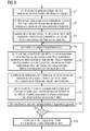
- a step S1 the control unit 10 is supplied with an instantaneous state Z and the instantaneous location of a point 14 of the rolling stock 1.
- the current location is related to the processing plant. He is at the beginning of the upstream part of the plant 2, in the embodiment of FIG. 2 and 3 that is, for example, in front of the first rolling stand 4 of the finishing train. If the finishing mill as shown by FIG. 2 Interstand cooling means 15 and also before the first rolling stand 4 of the finishing train such an intermediate stand cooling device 15 is arranged, the place is also in front of this intermediate stand cooling device 15. Optionally, the place may also be further forward.
- the place is arranged elsewhere.
- the location must be in front of the furnace, more precisely in front of the first heater 18 of the furnace.
- the location must be arranged before the beginning of the first part of the installation involved in the control method according to the invention or even further in front.
- the state Z can be specified to the control device 10 from the outside or otherwise predetermined. Alternatively, it can be detected metrologically. Also mixed forms are possible.
- a temperature measuring station 19 may be arranged, by means of which the current temperature T of the point 14 of the rolling stock 1 at whose surface is detected.
- the temperature profile over the thickness of the rolling stock 1 can be determined, for example, via a model. Such models are well known to those skilled in the art.
- the temperature T of the point 14 is often in a range in which, based on the temperature, it can be clearly decided in which phase state the rolling stock 1 is present.
- the temperature at the entrance of the finishing train is usually 1,000 ° C or more and thus far above the transformation temperature (about 723 ° C to 911 ° C) of steel. It is therefore known that the rolling stock 1 is in the phase state "austenite" in this case.
- the dimensions of the rolling stock 1 - for example, in a strip-shaped rolling stock, the strip thickness and the bandwidth - can be determined otherwise or the control device 10 may be known in other ways.
- the control device 10 uses a desired final state Z *, which the point 14 should have after passing through the downstream system part 3, to determine a desired final variable.
- the control device 10 can determine a desired end enthalpy, a desired final temperature, a desired phase fraction of the rolling stock 1, for example the proportion of austenite in steel etc.
- the desired end size of the control device 10 can also be specified.
- the detected point control means 10 implements a manipulated variable determiner 16 (see FIG FIGS. 10 and 11 ).
- the manipulated variable determiner 16 is initialized and started in the context of the step S3 with the state Z of the corresponding point 14.
- the manipulated variable detector 16 is coupled as a local manipulated variable determiner 16 to the respective point 14 of the rolling stock 1. He stays during the entire run of the point 14 through the treatment plant to this point 14 coupled.
- the implemented local manipulated variable determiner 16 always outputs a manipulated variable S to a device of the treatment system when the respective device acts on the respective point 14 of the rolling stock 1.
- the respective device influences the state Z of the rolling mill 1 passing through the treatment plant only locally, ie at the point at which the respective device is arranged.
- Other locations of the rolling stock 1 may be influenced by other facilities, but not by this facility, at the time the facility concerned acts on the point 14 of the rolling stock 1 concerned.
- the times at which the individual facilities of the treatment plant - for example, the cooling devices 6 and the interstand cooling devices 15 of FIG. 2 or the heaters 18 of the furnace of FIG. 4 - Act on the corresponding point 14 of the rolling stock 1, can be determined easily.
- the local manipulated variable determiner 16 applies a provisional manipulated variable profile.
- the local manipulated variable determiner 16 determines an expected state of the corresponding point 14 that is expected at the end of the forecast horizon within a forecast horizon based on a model 17 of the rolling stock 1 implemented within the control device 10.
- the local manipulated variable determiner 16 determines the expected state of the corresponding point 14 on the assumption that a currently given mass flow path, with which the corresponding point 14 is likely to pass through the treatment plant now and in the future, is not changed.
- time-dependent differential equations must be solved to determine the expected state. It is in this case, it is necessary to update the state in small time steps. In this case, therefore, the entire state history is determined.
- the corresponding models 17 are known as such and not the subject of the present invention. They are based on Fourier's equation of heat transfer, phase transformation models, heat transfer models, rolling models, etc.
- the local manipulated variable determiner 16 takes into account the manipulated variable S with which it next controls one of the devices Z influencing the state Z of the corresponding point 14.
- the local manipulated variable determiner 16 In individual cases - for example, if only a single heater 18 is present - the local manipulated variable determiner 16 outputs a manipulated variable S only at a single point in time. As a rule, however, the local command value determiner 16 outputs a manipulated variable S at several points in time to the device which directly influences the respective point 14 of the rolling stock 1. If the time interval of the further time points from the instant at which the local manipulated variable determinator outputs its manipulated variable S is smaller than the prognosis horizon of the local manipulated variable determiner 16, the local manipulated variable determiner 16 determines not only the manipulated variable S to be output next but also for the inside Each of the additional time points lying in the forecast horizon has an expected manipulated variable.
- the local manipulated variable determiner 16 assumes that the instantaneous mass flow profile, with which the point under consideration 14 is likely to pass now and in the future, does not change.
- the local command variable determiner 16 takes the determined manipulated variables determined into account when determining the state of the corresponding point 14 of the rolling stock 1 expected at the end of the forecast horizon.
- the local manipulated variable determinator 16 can be designed for this purpose, in particular, as a model predictive controller.
- the local manipulated variable determiner 16 determines its manipulated variable S by optimizing (i.e., minimizing or maximizing) an objective function.
- the deviation of the predicted state from a corresponding desired state of the point 14 of the rolling stock 1 is, of course, entered into the objective function.
- the states themselves or quantities derived from the states can be used here.
- control device 10 can also be predetermined for other locations of the treatment plant and / or for certain times, calculated from the arrival of the corresponding point 14 of the rolling stock 1 in the treatment plant, desired intermediate states. If this is the case, of course corresponding desired intermediate variables are determined for the corresponding locations and / or times and taken into account in the determination of the manipulated variable S of the local manipulated variable determiner 16.
- the objective function is usually a function with a large number of variables.
- the objective function is usually minimized (or maximized) according to the SQP procedure.
- the SQP process is known to those skilled in the art.
- the local manipulated variable determiner 16 outputs the manipulated variable S, which is determined by it, to be currently outputted in a step S7 to the device by means of which the state Z of the relevant point 14 can be influenced at the moment.
- the corresponding device determines the control device 10, for example by means of the already mentioned tracking. Furthermore, the respective local manipulated variable determiner 16 updates the state Z of the point 14 assigned to it.
- the local manipulated variable determiner 16 for example, on cooling devices 6, 15 act.
- the cooling devices can in the cooling section of FIG. 2 be arranged.
- the cooling devices can be arranged in the finishing train be, in the according to FIG. 2
- the local manipulated variable detector 16 act on the heaters 18 of the furnace.
- the corresponding devices are thus arranged in the upstream part of the plant 2.
- the prediction horizon of the local manipulated variable determiner 16 is suitably determined. In particular, it is determined in such a way that, at normal rolling speeds, the local command value determiner 16 is triggered at a point in time when it activates a device located in the upstream part of the installation 2 (for example in the embodiment according to FIG FIG. 2 one of the intermediate stand cooling devices 15 or in the embodiment according to FIG. 4 one of the heaters 18 of the furnace) takes into account a predicted state of the corresponding point 14 of the rolling stock 1, which is assumed by the corresponding point 14 of the rolling stock 1 only when the corresponding point 14 is located in the downstream part of the plant 3.
- FIG. 2 This situation is in FIG. 2 clearly illustrated by the fact that purely by way of example various possible forecasting horizons are drawn.
- the possible forecast horizons are in FIG. 2 designated by the reference numerals PH1 to PH3.
- the local manipulated variable determiner 16 when determining the manipulated variable S for the last interstate cooling device 15 of the finishing train, the local manipulated variable determiner 16 considers expected states of the corresponding point 14 of the rolling stock 1, which the corresponding point 14 assumes only in the cooling section. In accordance with the prognosis horizon PH2, this is already the case when the local manipulated variable determiner 16 determines the manipulated variable S for the penultimate interstate cooling device 15. According to the prognosis horizon PH3, the prognosis horizon may even be determined in such a way that it changes from the first influencing of the state of the Rolled material 1 in the upstream part of the plant 2 (ie, for example FIG.
- the forecast horizon can be static or dynamic.
- the forecast horizon at the beginning of the forecast is static until the forecast horizon reaches the end of the downstream plant part 3 (or in general of the last part of the plant involved in the control process according to the invention).
- the forecast horizon is preferably shortened dynamically, so that it extends from the respective current position of the local control variable determiner 16 associated point 14 to the end of the downstream part of the plant 3.
- the prognosis horizon like a telescope rod, in which one end is bound to the point 14 assigned to the respective local manipulated variable determiner 16 and the other end "protrudes into the future”.
- the telescopic rod remains extended until the other end "abuts" the end of the downstream equipment part 3. Thereafter, the telescopic rod is "pushed together" accordingly.
- step S8 and S9 the control device 10 checks whether the relevant point 14 has exited the downstream system part 3, that is, for example, in the embodiment of FIG FIG. 2 has left the cooling section. If not, the controller 10 returns to step S4. If so, the controller 10 proceeds to step S10. In step S10, the control device 10 deletes the local command value determiner 16 implemented for the leaked point 14. The leaked point 14 is not considered further, at least in the context of the control method according to the invention.
- the procedure of FIG. 6 is executed clocked.
- a new point 14 of the rolling stock 1 is detected in each case with a work cycle which is generally between 0.1 and 1.0 seconds.
- Preferred values of the power stroke are between 0.2 and 0.5 seconds, for example 0.3 seconds.
- the controller 10 performs the above in connection with FIG. 6 therefore explained in parallel for all points 14, which are at a certain time in the treatment plant.
- each of the points 14 therefore corresponds to a portion of the rolling stock 1 whose length is the product of the power stroke with the instantaneous input speed v, with which the corresponding point 14 enters the upstream part of the plant 2.
- the method comprises steps S11 to S24.
- the steps S11 to S20 correspond to 1: 1 with the steps S1 to S10 of FIG. 6 , for the steps S11 to S20, therefore, no further explanations are required.
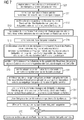
- step S21 the controller 10 implements a global manipulated variable determiner 20 (see FIG FIGS. 10 and 11 ).
- the global manipulated variable determinator 20 acts on the mass flow of the rolling stock 1 and thus on all points 14 / sections 14 of the rolling stock 1 at the same time.
- the integration of the global manipulated variable determinant 20 in the control method according to the invention is achieved by the steps S22 and S23.
- step S22 the global manipulated variable determiner 20 determines a new mass flow profile. The determination is made on the basis of the manipulated variables S determined by the local manipulated variable detectors 16 in step S16.
- the global manipulated variable determinator 20 preferably takes into account both the manipulated variables S to be output by the local manipulated variable detectors 16 in step S17 and those determined by the local manipulated variable detectors 16 expected manipulated variables that are within the forecast horizon of the local manipulated variable determinants 16.
- the first three of the variables mentioned are for each manipulated variable (regardless of whether output in step S15 or only within the forecast horizon) in each case to the device 6, 15, 18, to which the respective local manipulated variable determiner 16 acts at the corresponding output time.
- the consideration of the maximum possible manipulated variable change is only meaningful if the global manipulated variable determinator 20 sets a number of manipulated variables S in relation to one another, which are output from the same local manipulated variable determiner 16 or from several local manipulated variable detectors 16 to the same device 6, 15, 18 in succession.
- the manipulated variables S 'of the global manipulated variable determiner 20 can also be evaluated.
- the global manipulated variable determiner 20 attempts to optimize the evaluation in step S22. For example, the global manipulated variable determiner 20 attempts to keep the manipulated variables S to be output and expected by the local manipulated variable determinants 16 within the permissible range, spaced as far as possible from the manipulation limits and to keep the expected rates of change within the permissible frame. At the same time, the global manipulated variable determinant 20 takes into account the corresponding limits for the mass flow.
- the global manipulated variable determiner 20 can also be designed as a model-predictive controller.
- step S23 the local manipulated variable determinants 16 determine their final manipulated variables S on the basis of the provisional manipulated variables, the mass flow profile newly determined in step S22, and the previously valid mass flow profile.
- step S16 in which the local manipulated variable investigators have to calculate the expected state of the corresponding section 14 of the rolling stock 1 up to its forecast horizon
- step S20 it may be sufficient to scale only the manipulated variables S currently to be output. Even a complete recalculation is not excluded.
- the manipulated variables S determined in step S16 are only provisional manipulated variables S.
- step S17 only the local manipulated variable determinants 16 output their manipulated variable S to the corresponding devices 6, 15, 18.
- step S24 which is carried out virtually simultaneously to step S17, the global manipulated variable determiner 20 outputs to actuators for the mass flow - for example to speed controls 21 for the rolling stands 4 - corresponding manipulated variables S 'from.
- the global manipulated variable determiner 20 outputs its manipulated variables S 'at a point in time at which a plurality of sections 14 in the upstream system part 2 (according to FIG FIG. 2 and FIG. 3 for example, the finishing train) are located.
- the global manipulated variable determiner 20 also has a prognosis horizon.
- the forecast horizon can be analogous to FIG. 2 be determined as needed. It can be equal to the forecast horizon of the local Be manipulated variable detector 16 or be different from this.
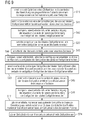
- FIG. 3 shows - purely by way of example - some possible prognosis horizons of the global manipulated variable determinant 20, in FIG. 3 denoted PH4 and PH5.
- the forecast horizon extends from the beginning of the upstream plant part 2 to the first device 6 of the downstream plant part 3, by means of which the state of the rolling stock 1 can be locally influenced.
- the input variables of the global manipulated variable determinant 20 also include expected states of sections 14 of the rolling stock 1 that have not yet entered the upstream system part 2. For this purpose, it is only necessary to implement, initialize and start the corresponding local command value determiner 16 in advance for each section 14. If this local manipulated variable determiner 16 continues to determine already expected local manipulated variables for the portion 14 of the rolling stock 1 that has not yet entered the upstream part 2, the input variables of the global manipulated variable determinator 20 also include these expected manipulated variables and the corresponding evaluation variables.
- FIG. 7 The procedure of FIG. 7 is also according to a treatment plant FIG. 2 applicable. It is also according to a treatment plant FIG. 4 applicable.
- the control device 20 for at least one of the state Z of the rolling stock 1 influencing devices 6, 15, 18, 21 within a further (second) forecast horizon expected states of the respective device 6, 15, 18, 21 and determines the states of the respective device 6, 15, 18, 21 expected during this prognosis horizon in the determination of the manipulated variables S output by the manipulated variable determinants 16, 20 to the respective device 6, 15, 18, 21 'S' taken into account.
- FIG. 8 shows a possible embodiment of FIG. 6 .
- FIG. 9 a possible embodiment of FIG. 7 ,
- step S31 the controller 10 determines, for at least one of the devices 6, 15, 18, which are influenced by the local command value determinants 16, their expected states.
- step S32 if necessary, the control device 10, taking into account the expected states of the respective device 6, 15, 18, corrects the manipulated variables S output from the local manipulated variable detectors 16 to the devices 6, 15, 18.
- a specific cooling device 6 of the cooling section is acted upon in a specific working cycle of the control device 10 by a specific section 14 of the rolling stock 1 with a coolant (for example water).
- a coolant for example water
- the same cooling device 6 acts on the next section 14, in the next but one working cycle on the next but one section 14.
- the local manipulated variable determiner 16 which acts on the said cooling device in the specific working cycle, has as relative Control value 80% determined.
- the cooling device 6 following the first-mentioned cooling device 6 should be controlled by the three local manipulated variable detectors just mentioned with 60%, 60% and 40%. Assume further that the cooling means 6 are of the same design and can change their coolant flow from one stroke to the next by a maximum of 25%.
- steps S31 and S32 are not present, only the section 6 passing first through the two coolers 6 is correctly cooled at 80% and 60%.
- the second section can only be cooled by the first cooling device with 55%, because the first cooling device 6, the flow rate of coolant, starting from 80%, can not throttle faster. The error is 5%.
- the next section is cooled at 30% instead of 20%. The reason is the same: the corresponding cooling device 6 can only throttle the flow of coolant from 55% to 30%.
- steps S41 and S42 may be present.
- the steps S41 and S42 correspond in content to the steps S31 and S32 of FIG. 8 .
- steps S43 and S44 there may be steps S43 and S44 inserted after step S23.
- the steps S43 and S44 can also be described in terms of the steps S31 and S32 of FIG. 8 correspond.
- the presence of steps S43 and S44 in addition to steps S41 and S42 may therefore be particularly useful because the manipulated variables S of the local manipulated variable determinants 16 may have changed due to step S22.
- steps S45 and S46 may furthermore be useful to follow steps S45 and S46 in step S22.
- steps S45 and S46 analogous procedures are taken with respect to the mass flow actuators 21 in steps S31 and S32.
- the control device 10 which implements the control method according to the invention, must have a high computing power. It may be possible to use this computing power according to the representation of FIG. 10 in a single, unified, not divided into several sub-control devices to realize control device 10, which controls the entire treatment plant. Alternatively, it is according to the representation of FIG. 11 possible that the control device 10 is divided into a plurality of sub-control devices 22. However, if such a division is made, each implemented local manipulated variable determiner 16 is preferably implemented on one and the same subcontroller 22 during the entire passage of the respective section 14 of the rolling stock 1 through the treatment plant. It is therefore preferably not the case that the respective local manipulated variable determiner 16, for example, from the in FIG. 11 left illustrated sub-controller 22 to the in FIG. 11 Partial control device 22 shown on the right is transmitted when - for example - the corresponding portion 14 of the rolling stock 1 from the upstream part of the plant 2 in the downstream part of the plant 3 passes.
- the present invention has many advantages.
- an inter-plant forecast is realized for the first time.
- a model prediction and, associated with it, a prognosis are already being used.
- the forecasts are made in the prior art, however, always limited to the respective part of the plant 2, 3.
- the oven as upstream unit part 2 to use to set the final rolling temperature at the outlet of the finishing train as a subordinate part of the plant 3. Only the forecast horizon has to be chosen sufficiently large.
- the input speed v, with which the rolling stock 1 enters the finishing train may be determined, for example, because the finishing mill, as shown in FIG FIG. 5 on the one hand as a further upstream device 7 the roughing and this in turn the continuous casting 8 are arranged upstream.
- For a casting speed of the continuous casting 8 is essentially determined by the solidification behavior of the cast metal and adjustable only within very narrow limits.
- the input speed v of the rolling stock 1 is determined in this case by the more or less fixed predetermined casting speed and the cross-sectional decrease of the rolling stock 1 in the roughing train.
Landscapes
- Engineering & Computer Science (AREA)
- Mechanical Engineering (AREA)
- Control Of Metal Rolling (AREA)
- Feedback Control In General (AREA)
Priority Applications (5)
| Application Number | Priority Date | Filing Date | Title |
|---|---|---|---|
| EP09171068A EP2301685A1 (fr) | 2009-09-23 | 2009-09-23 | Procédé de commande pour une installation de traitement d'un produit de laminage étendu en longueur |
| PL10754744T PL2480351T3 (pl) | 2009-09-23 | 2010-09-17 | Sposób sterowania instalacją do obróbki dla wydłużonego materiału walcowanego |
| EP10754744.0A EP2480351B1 (fr) | 2009-09-23 | 2010-09-17 | Procédé de commande pour une installation de traitement d'un matériau laminé allongé |
| PCT/EP2010/063663 WO2011036093A2 (fr) | 2009-09-23 | 2010-09-17 | Procédé de commande pour une installation de traitement d'un matériau laminé allongé |
| CN201080042639.6A CN102497941B (zh) | 2009-09-23 | 2010-09-17 | 用于延长的轧件的处理设备的控制方法 |
Applications Claiming Priority (1)
| Application Number | Priority Date | Filing Date | Title |
|---|---|---|---|
| EP09171068A EP2301685A1 (fr) | 2009-09-23 | 2009-09-23 | Procédé de commande pour une installation de traitement d'un produit de laminage étendu en longueur |
Publications (1)
| Publication Number | Publication Date |
|---|---|
| EP2301685A1 true EP2301685A1 (fr) | 2011-03-30 |
Family
ID=41820136
Family Applications (2)
| Application Number | Title | Priority Date | Filing Date |
|---|---|---|---|
| EP09171068A Withdrawn EP2301685A1 (fr) | 2009-09-23 | 2009-09-23 | Procédé de commande pour une installation de traitement d'un produit de laminage étendu en longueur |
| EP10754744.0A Not-in-force EP2480351B1 (fr) | 2009-09-23 | 2010-09-17 | Procédé de commande pour une installation de traitement d'un matériau laminé allongé |
Family Applications After (1)
| Application Number | Title | Priority Date | Filing Date |
|---|---|---|---|
| EP10754744.0A Not-in-force EP2480351B1 (fr) | 2009-09-23 | 2010-09-17 | Procédé de commande pour une installation de traitement d'un matériau laminé allongé |
Country Status (4)
| Country | Link |
|---|---|
| EP (2) | EP2301685A1 (fr) |
| CN (1) | CN102497941B (fr) |
| PL (1) | PL2480351T3 (fr) |
| WO (1) | WO2011036093A2 (fr) |
Cited By (4)
| Publication number | Priority date | Publication date | Assignee | Title |
|---|---|---|---|---|
| EP2527053A1 (fr) * | 2011-05-24 | 2012-11-28 | Siemens Aktiengesellschaft | Procédé de commande pour une voie de laminage |
| EP2527054A1 (fr) * | 2011-05-24 | 2012-11-28 | Siemens Aktiengesellschaft | Procédé de commande pour une voie de laminage |
| EP2540404A1 (fr) * | 2011-06-27 | 2013-01-02 | Siemens Aktiengesellschaft | Procédé de commande pour un laminoir à bandes à chaud |
| EP3060358B1 (fr) | 2013-10-25 | 2017-11-15 | SMS group GmbH | Train de laminage à chaud de bandes d'aluminium et procédé de laminage à chaud d'une bande d'aluminium |
Families Citing this family (1)
| Publication number | Priority date | Publication date | Assignee | Title |
|---|---|---|---|---|
| EP3623068B1 (fr) | 2018-09-12 | 2021-07-14 | Primetals Technologies Germany GmbH | Dispositifs d'application de tunnels de refroidissement à l'aide d'un second embranchement |
Citations (5)
| Publication number | Priority date | Publication date | Assignee | Title |
|---|---|---|---|---|
| JPS63168211A (ja) * | 1986-12-27 | 1988-07-12 | Sumitomo Metal Ind Ltd | 熱延プロセスにおける温度制御方法 |
| US6286349B1 (en) * | 1997-03-11 | 2001-09-11 | Betriebsforschungsinstitut Vdeh-Institut Fur Angewandte Forschung Gmbh | Flatness measurement system for metal strip |
| DE10156008A1 (de) | 2001-11-15 | 2003-06-05 | Siemens Ag | Steuerverfahren für eine einer Kühlstrecke vorgeordnete Fertigstraße zum Walzen von Metall-Warmband |
| EP1596999A2 (fr) * | 2003-02-25 | 2005-11-23 | Siemens Aktiengesellschaft | Procede de regulation de la temperature d'une bande metallique, en particulier dans un parcours de refroidissement |
| US7310981B2 (en) | 2003-02-25 | 2007-12-25 | Siemens Aktiengesellschaft | Method for regulating the temperature of strip metal |
Family Cites Families (3)
| Publication number | Priority date | Publication date | Assignee | Title |
|---|---|---|---|---|
| ATE189627T1 (de) * | 1995-09-06 | 2000-02-15 | Schloemann Siemag Ag | Warmbandproduktionsanlage für das walzen von dünnem walzband |
| NL1003293C2 (nl) * | 1996-06-07 | 1997-12-10 | Hoogovens Staal Bv | Werkwijze en inrichting voor het vervaardigen van een stalen band. |
| JP2004034056A (ja) * | 2002-07-01 | 2004-02-05 | Sumitomo Light Metal Ind Ltd | 熱間圧延機における温度制御方法及び温度制御装置 |
-
2009
- 2009-09-23 EP EP09171068A patent/EP2301685A1/fr not_active Withdrawn
-
2010
- 2010-09-17 PL PL10754744T patent/PL2480351T3/pl unknown
- 2010-09-17 EP EP10754744.0A patent/EP2480351B1/fr not_active Not-in-force
- 2010-09-17 CN CN201080042639.6A patent/CN102497941B/zh not_active Expired - Fee Related
- 2010-09-17 WO PCT/EP2010/063663 patent/WO2011036093A2/fr active Application Filing
Patent Citations (8)
| Publication number | Priority date | Publication date | Assignee | Title |
|---|---|---|---|---|
| JPS63168211A (ja) * | 1986-12-27 | 1988-07-12 | Sumitomo Metal Ind Ltd | 熱延プロセスにおける温度制御方法 |
| US6286349B1 (en) * | 1997-03-11 | 2001-09-11 | Betriebsforschungsinstitut Vdeh-Institut Fur Angewandte Forschung Gmbh | Flatness measurement system for metal strip |
| DE10156008A1 (de) | 2001-11-15 | 2003-06-05 | Siemens Ag | Steuerverfahren für eine einer Kühlstrecke vorgeordnete Fertigstraße zum Walzen von Metall-Warmband |
| US7197802B2 (en) | 2001-11-15 | 2007-04-03 | Siemens Aktiengesellschaft | Control method for a finishing train and a finishing train |
| EP1596999A2 (fr) * | 2003-02-25 | 2005-11-23 | Siemens Aktiengesellschaft | Procede de regulation de la temperature d'une bande metallique, en particulier dans un parcours de refroidissement |
| EP1596999B1 (fr) | 2003-02-25 | 2006-12-20 | Siemens Aktiengesellschaft | Procede de regulation de la temperature d'une bande metallique, en particulier dans un parcours de refroidissement |
| US7251971B2 (en) | 2003-02-25 | 2007-08-07 | Siemens Aktiengesellschaft | Method for regulating the temperature of strip metal |
| US7310981B2 (en) | 2003-02-25 | 2007-12-25 | Siemens Aktiengesellschaft | Method for regulating the temperature of strip metal |
Cited By (22)
| Publication number | Priority date | Publication date | Assignee | Title |
|---|---|---|---|---|
| RU2576971C2 (ru) * | 2011-05-24 | 2016-03-10 | Прайметалз Текнолоджиз Джермани Гмбх | Способ управления для прокатного стана |
| EP2697002B1 (fr) | 2011-05-24 | 2015-08-12 | Primetals Technologies Germany GmbH | Procédé de commande pour train de laminoir |
| WO2012159868A1 (fr) | 2011-05-24 | 2012-11-29 | Siemens Aktiengesellschaft | Procédé de commande pour train de laminoir |
| WO2012159866A1 (fr) | 2011-05-24 | 2012-11-29 | Siemens Aktiengesellschaft | Procédé de commande pour train de laminage |
| US9751165B2 (en) | 2011-05-24 | 2017-09-05 | Primetals Technologies Germany Gmbh | Control method for mill train |
| US9547290B2 (en) | 2011-05-24 | 2017-01-17 | Primetals Technologies Germany Gmbh | Control method for a rolling train |
| CN103547384A (zh) * | 2011-05-24 | 2014-01-29 | 西门子公司 | 用于轧机列的控制方法 |
| CN103547385A (zh) * | 2011-05-24 | 2014-01-29 | 西门子公司 | 用于轧机列的控制方法 |
| CN103547384B (zh) * | 2011-05-24 | 2016-08-24 | 普锐特冶金技术德国有限公司 | 用于轧机列的控制方法 |
| EP2697001B1 (fr) | 2011-05-24 | 2015-08-12 | Primetals Technologies Germany GmbH | Procédé de commande pour train de laminage |
| EP2527054A1 (fr) * | 2011-05-24 | 2012-11-28 | Siemens Aktiengesellschaft | Procédé de commande pour une voie de laminage |
| US20140129023A1 (en) * | 2011-05-24 | 2014-05-08 | Siemens Aktiengesellschaft | Control method for a rolling train |
| US20140088752A1 (en) * | 2011-05-24 | 2014-03-27 | Siemens Aktiengesellschaft | Control method for mill train |
| RU2583550C2 (ru) * | 2011-05-24 | 2016-05-10 | Прайметалз Текнолоджиз Джермани Гмбх | Способ управления прокатным станом |
| CN103547385B (zh) * | 2011-05-24 | 2016-03-09 | 西门子公司 | 用于轧机列的控制方法 |
| EP2527053A1 (fr) * | 2011-05-24 | 2012-11-28 | Siemens Aktiengesellschaft | Procédé de commande pour une voie de laminage |
| CN103619501B (zh) * | 2011-06-27 | 2016-01-20 | 西门子公司 | 用于热轧带材生产线的控制方法 |
| CN103619501A (zh) * | 2011-06-27 | 2014-03-05 | 西门子公司 | 用于热轧带材生产线的控制方法 |
| WO2013000677A1 (fr) | 2011-06-27 | 2013-01-03 | Siemens Aktiengesellschaft | Procédé de commande pour un train à feuillards à chaud |
| EP2540404A1 (fr) * | 2011-06-27 | 2013-01-02 | Siemens Aktiengesellschaft | Procédé de commande pour un laminoir à bandes à chaud |
| US9815100B2 (en) | 2011-06-27 | 2017-11-14 | Primetals Technologies Germany Gmbh | Method for controlling a hot strip rolling line |
| EP3060358B1 (fr) | 2013-10-25 | 2017-11-15 | SMS group GmbH | Train de laminage à chaud de bandes d'aluminium et procédé de laminage à chaud d'une bande d'aluminium |
Also Published As
| Publication number | Publication date |
|---|---|
| PL2480351T3 (pl) | 2014-09-30 |
| EP2480351B1 (fr) | 2014-04-30 |
| WO2011036093A3 (fr) | 2011-11-10 |
| EP2480351A2 (fr) | 2012-08-01 |
| WO2011036093A2 (fr) | 2011-03-31 |
| CN102497941A (zh) | 2012-06-13 |
| CN102497941B (zh) | 2014-10-15 |
Similar Documents
| Publication | Publication Date | Title |
|---|---|---|
| EP2566633B1 (fr) | Procédé pour faire fonctionner un train finisseur avec prédiction de la vitesse de commande | |
| EP1444059B1 (fr) | Procede pour commander un train finisseur monte en amont d'une section de refroidissement et concu pour laminer des feuillards metalliques a chaud | |
| EP2697001B1 (fr) | Procédé de commande pour train de laminage | |
| EP2456897B1 (fr) | Procédé de commande et/ou de réglage d'un four à induction pour un laminoir, dispositif de commande et/ou de réglage pour un laminoir et laminoir destiné à la fabrication d'un produit de laminage | |
| DE19963186B4 (de) | Verfahren zur Steuerung und/oder Regelung der Kühlstrecke einer Warmbandstrasse zum Walzen von Metallband und zugehörige Vorrichtung | |
| EP2603333B1 (fr) | Procédé de détermination en temps réel de la température et de la géométrie d'un feuillard métallique laminé à chaud dans un train finisseur | |
| EP2712332B1 (fr) | Procédé de commande pour un train à feuillards à chaud | |
| EP2697002B1 (fr) | Procédé de commande pour train de laminoir | |
| EP2480351B1 (fr) | Procédé de commande pour une installation de traitement d'un matériau laminé allongé | |
| DE102006047718A1 (de) | Verfahren zur Nachverfolgung des physikalischen Zustands eines Warmblechs oder Warmbands im Rahmen der Steuerung einer Grobblechwalzstraße zur Bearbeitung eines Warmblechs oder Warmbands | |
| EP1596999B2 (fr) | Procede de regulation de la temperature d'une bande metallique, en particulier dans un parcours de refroidissement | |
| EP2603332A1 (fr) | Procédé de détermination de grandeurs de commande d'un train de laminoir comportant plusieurs cages pour laminer une bande de métal | |
| EP3071343B1 (fr) | Procédé de fonctionnement pour une voie de refroidissement et voie de refroidissement | |
| EP3495056A1 (fr) | Commande améliorée de la gestion de l'eau d'un circuit de refroidissement | |
| DE10321791A1 (de) | Verfahren zur Regelung der Temperatur eines Metallbandes, insbesondere in einer Fertigstraße zum Walzen von Metall-Warmband | |
| EP4364867A1 (fr) | Laminage d'acier avec détection technique de mesure de la conversion de phase | |
| WO2023285078A1 (fr) | Utilisation de marge de tolérance pour densité dépendant de l'état lors de la résolution d'une équation de conductivité thermique | |
| EP2755134A1 (fr) | Commande d'une installation technique avec CPU et GPU | |
| WO2024208661A1 (fr) | Procédé de fonctionnement d'une installation de coulée-laminage continue à cage refouleuse | |
| DE10321792A1 (de) | Verfahren zur Regelung der Temperatur eines Metallbandes, insbesondere in einer Kühlstrecke |
Legal Events
| Date | Code | Title | Description |
|---|---|---|---|
| PUAI | Public reference made under article 153(3) epc to a published international application that has entered the european phase |
Free format text: ORIGINAL CODE: 0009012 |
|
| AK | Designated contracting states |
Kind code of ref document: A1 Designated state(s): AT BE BG CH CY CZ DE DK EE ES FI FR GB GR HR HU IE IS IT LI LT LU LV MC MK MT NL NO PL PT RO SE SI SK SM TR |
|
| AX | Request for extension of the european patent |
Extension state: AL BA RS |
|
| STAA | Information on the status of an ep patent application or granted ep patent |
Free format text: STATUS: THE APPLICATION IS DEEMED TO BE WITHDRAWN |
|
| 18D | Application deemed to be withdrawn |
Effective date: 20111001 |