EP2301397B1 - Flame tamers and arrangement thereof for barbeque grills - Google Patents
Flame tamers and arrangement thereof for barbeque grills Download PDFInfo
- Publication number
- EP2301397B1 EP2301397B1 EP20090171637 EP09171637A EP2301397B1 EP 2301397 B1 EP2301397 B1 EP 2301397B1 EP 20090171637 EP20090171637 EP 20090171637 EP 09171637 A EP09171637 A EP 09171637A EP 2301397 B1 EP2301397 B1 EP 2301397B1
- Authority
- EP
- European Patent Office
- Prior art keywords
- burner box
- barbeque
- flame
- barbeque burner
- extending
- Prior art date
- Legal status (The legal status is an assumption and is not a legal conclusion. Google has not performed a legal analysis and makes no representation as to the accuracy of the status listed.)
- Active
Links
Images


Classifications
-
- A—HUMAN NECESSITIES
- A47—FURNITURE; DOMESTIC ARTICLES OR APPLIANCES; COFFEE MILLS; SPICE MILLS; SUCTION CLEANERS IN GENERAL
- A47J—KITCHEN EQUIPMENT; COFFEE MILLS; SPICE MILLS; APPARATUS FOR MAKING BEVERAGES
- A47J37/00—Baking; Roasting; Grilling; Frying
- A47J37/06—Roasters; Grills; Sandwich grills
- A47J37/07—Roasting devices for outdoor use; Barbecues
- A47J37/0786—Accessories
-
- A—HUMAN NECESSITIES
- A47—FURNITURE; DOMESTIC ARTICLES OR APPLIANCES; COFFEE MILLS; SPICE MILLS; SUCTION CLEANERS IN GENERAL
- A47J—KITCHEN EQUIPMENT; COFFEE MILLS; SPICE MILLS; APPARATUS FOR MAKING BEVERAGES
- A47J37/00—Baking; Roasting; Grilling; Frying
- A47J37/06—Roasters; Grills; Sandwich grills
- A47J37/067—Horizontally disposed broiling griddles
- A47J37/0682—Horizontally disposed broiling griddles gas-heated
-
- A—HUMAN NECESSITIES
- A47—FURNITURE; DOMESTIC ARTICLES OR APPLIANCES; COFFEE MILLS; SPICE MILLS; SUCTION CLEANERS IN GENERAL
- A47J—KITCHEN EQUIPMENT; COFFEE MILLS; SPICE MILLS; APPARATUS FOR MAKING BEVERAGES
- A47J37/00—Baking; Roasting; Grilling; Frying
- A47J37/06—Roasters; Grills; Sandwich grills
- A47J37/07—Roasting devices for outdoor use; Barbecues
- A47J37/0704—Roasting devices for outdoor use; Barbecues with horizontal fire box
- A47J37/0713—Roasting devices for outdoor use; Barbecues with horizontal fire box with gas burners
Definitions
- the present invention relates to a design of flame tamer for use in a barbeque burner box and more particularly to flame tamers that have protruding openings for guiding the heat energy from heat sources toward particular directions so that the heat energy can be evenly distributed to enhance the cooking efficiency.
- the invention relates also to ways of arrangement of the flame tamers in the barbeque burner box.
- a known flame tamer for a barbeque burner box is to be bridged on a barbeque burner box above a heat source.
- This design of flame tamer has a double-beveled configuration. Small holes may be made on the flame tamer for allowing upward hot air to pass.
- this design of flame tamer cannot distribute heat energy evenly throughout the whole area of the barbeque cooking surface. During cooking, there is a temperature difference between the hot spot around the center of the barbeque cooking surface and the cold spot around the border of the barbeque grill. This temperature difference results in low cooking efficiency and waste of fuel energy, and the food tends to be overcooked or undercooked.
- US Pat. No. 6332395 teaches the use of a board in a barbeque burner box above a heat source to enhance heat distribution. However, this arrangement cannot evenly distribute heat energy throughout the whole cooking area. US Pat. No. 5617778 teaches the application of apertures to guide heat source. This measure still cannot achieve even distribution of heat source. US Pat. No. 6187359 teaches the use of a resistant metal plate for placing over the burners. The plate has a series of louvered openings which allow heat to rise from the barbeque flames while blocking the flames.
- US 4 446 776 discloses is a heating appliance comprising a first and second section, the first section having a top surface supported by side walls via an interconnecting conical transition section.
- the top surface is formed with a peripherally extending raised rim adjacent a plurality of apertures arranged in groups wherein adjacent groups are separated by a spacing having a louvered vent therein.
- a second raised rim separates a second group of louvered vents which are radially aligned with the spacing between adjacent apertures within each group of apertures. Air pockets in the surface underside are aligned with the raised rims.
- a cover or second section having a plurality of openings is formed with a declined extending lip for positioning on the conical transition section;
- US 5 617 778 discloses a gas barbecue having a rectangular body, gas control means, a cooking grill, and a burner assembly.
- the burner assembly includes an elongate tube burner and a generally L-shaped tube burner having a primary tube member and a secondary tube member intersecting the primary tube member thereby forming the general L shape.
- the free end of the secondary tube member is positioned in close proximity to the elongate tube burner such that the ignition of the elongate tube burner causes cross-ignition of the L-shaped tube burner when gas is supplied thereto.
- US 2 884 849 discloses a grill for cooking food comprising a body of generally rectangular configuration formed of sheet material having a main portion formed with longitudinally extending corrugations providing upwardly opening grooves and with down-turned sides whose lower marginal portions are in-turned to form with said main portion inwardly opening channels, said sides being of greater height at one end of the body than at the other end thereof so that the main portion will be disposed in a sloping position from end to end when the body is supported with said in-turned portions resting on a horizontally positioned support, said grooves being open at their lower ends to permit liquid to flow off of said main portion along the grooves when the body is so upported, said main portion having openings in the sides of said grooves above the bottoms of the grooves and a liquid receiving and rigidifying member removably supported in said channels and extending beyond the lower ends of said grooves in position to receive liquid from the grooves; said member having a portion positioned for engagement with said corrugations beneath the bottoms of said grooves along the lower end of said
- the present invention has been accomplished under the circumstances in view. It is the object of the present invention to provide a flame tamer for bridging in a barbeque burner box in a barbeque grill set to distribute heat energy evenly over the barbeque cooking surface so that the food can be cooked evenly and efficiently, thus saving much energy consumption.
- a flame tamer for use in a barbeque burner box is to be bridged on two opposite peripheral walls, namely, the front and rear walls of the barbeque burner box, having at least one protruding opening for guiding the hot air from the heat source in the barbeque burner box toward at least one of the peripheral walls of the barbeque burner box so that the food can be cooked evenly and efficiently on the barbeque cooking surface.
- a left flame tamer, a right flame tamer and at least one middle flame tamer are bridged on the front wall and rear wall of the barbeque burner box above the heat sources.
- the left flame tamer is disposed close to the left sidewall of the barbeque burner box, having at least one first protruding opening extending in a direction toward the left sidewall of the barbeque burner box and at least one second protruding opening extending in a direction toward the front wall of the barbeque burner box.
- the right flame tamer is disposed close to the right sidewall of the barbeque burner box, having at least one first protruding opening extending in a direction toward the right sidewall of the barbeque burner box and at least one second protruding opening extending in a direction toward the front wall of the barbeque burner box.
- the at least one middle flame tamer is set between the left flame tamer and the right flame tamer.
- Each middle flame tamer has at least one first protruding opening disposed at one end thereof and extending in a direction toward the front wall of the barbeque burner box.
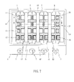
- a barbeque burner box 4 of a barbeque grill set has four peripheral walls 41, 42, 43 and 44.
- the flame tamers 1, 2, 3 commonly have at least one protruding opening facing one of the peripheral walls 41, 42, 43 or 44 of the barbeque burner box 4 (see FIG. 7 ) for guiding the upward flow of hot air from the heat sources 5 (see FIG, 8 and FIG. 9 ) toward the cold spot of the barbeque burner box 4 to rapidly and evenly distribute the thermal energy over the whole area of the barbeque grill 6 to cook the food on the barbeque grill 6, thereby saving energy consumption and preventing the food from being unevenly cooked.
- the first flame tamer 1 in accordance with the first embodiment of the present invention is supported between two opposite peripheral walls, namely, the front wall 42 and the rear wall 44 of the barbeque burner box 4 near one side wall 41 (the left side of the barbeque burner box 4), having at least one, for example three, first protruding openings 11 arranged in line and extending in a direction toward the left side wall 41 and at least one, for example two, second protruding openings 12 extending in a direction toward the front wall 42.
- At least one second flame tamer 2 in accordance with the second embodiment of the present invention is supported between the front wall 42 and the rear wall 44 of the barbeque burner box 4 in the middle, having at least one, for example two, protruding openings 21 extending in a direction toward the front wall 42.
- the number of the second flame tamer 2 to be bridged on the barbeque burner box 4 is determined according to the size of the barbeque burner box 4. According to the application example shown in FIG. 7 , two pieces of second flame tamers 2 are bridged on the barbeque burner box 4 in the middle.
- the third flame tamer 3 in accordance with the third embodiment of the present invention is supported between the front wall 42 and the rear wall 44 of the barbeque burner box 4 near the other side wall 43 (the right side of the barbeque burner box 4), having at least one, for example three, first protruding openings 31 arranged in line and extending in a direction toward the right side wall 43 of the barbeque burner box 4 and at least one, for example two, second protruding openings 32 extending in a direction toward the front wall 42.
- the aforesaid flame tamers 1, 2 and 3 are bridged on the barbeque burner box 4 above the heat sources 5.
- the heat sources 5 are elongated gas burners (see FIG. 9 ) controllable by respective burner control knobs 7. When the heat sources 5 are activated, heat energy is transferred to the flame tamers 1, 2 and 3 and evenly distributed through the whole area of the barbeque grill 6.
- the protruding openings 11, 12, 21, 31 and 32 of the flame tamers 1, 2 and 3 guide part of the heat energy toward the border area of the barbeque burner box 4 so that heat energy is evenly distributed throughout the whole area of the barbeque grill 6 to cook food thoroughly, thus achieving high cooking efficiency and preventing the food from being overcooked or undercooked.
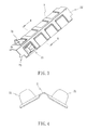
- Each of the flame tamers 1, 2 and 3 has a plate body with a double-beveled configuration.
- Each of the protruding openings (11, 12, 21, 31 or 32) comprises an opening on the plate body and a chute protruding over the opening in a certain direction for guiding the hot air flowing through the opening. Except the protruding openings 11, 12, 21, 31 or 32, the plate body forming each of the flame tamers is an enclosed surface.
- the flame tamers 1, 2 and 3 preferably have a concave convex surface configuration.
- the flame tamer 1 further has a front extension portion 14 and a rear extension portion 13 for supporting on the front wall 42 and the rear wall 44 of the barbeque burner box 4 respectively.
- the flame tamer 2 further has a front extension portion 23 and a rear extension portion 22
- the flame tamer 3 further has a front extension portion 34 and a rear extension portion 33, for supporting on the front wall 42 and the rear extension wall 44 respectively.
- the heat sources 5 of the barbeque burner box 4 are not limited to fuel gas. Further, the configurations of the flame tamers 1, 2 and 3 may be changed, however the protruding openings 11, 12, 21, 31 and 32 are requisite structural features. As far as the length, width and material are concerned, they are determined according to actual needs. However, excellent heat distribution is necessary. Further, the shape, opening and elevation angle of the protruding openings 11, 12, 21, 31 and 32 as well as the positioning structure between the flame tamers 1, 2 and 3 and the front wall 42 and the rear wall 44 of the barbeque burner box 4 can be altered.
Landscapes
- Engineering & Computer Science (AREA)
- Food Science & Technology (AREA)
- Baking, Grill, Roasting (AREA)
Description
- The present invention relates to a design of flame tamer for use in a barbeque burner box and more particularly to flame tamers that have protruding openings for guiding the heat energy from heat sources toward particular directions so that the heat energy can be evenly distributed to enhance the cooking efficiency. The invention relates also to ways of arrangement of the flame tamers in the barbeque burner box.
- A known flame tamer for a barbeque burner box is to be bridged on a barbeque burner box above a heat source. This design of flame tamer has a double-beveled configuration. Small holes may be made on the flame tamer for allowing upward hot air to pass. However, this design of flame tamer cannot distribute heat energy evenly throughout the whole area of the barbeque cooking surface. During cooking, there is a temperature difference between the hot spot around the center of the barbeque cooking surface and the cold spot around the border of the barbeque grill. This temperature difference results in low cooking efficiency and waste of fuel energy, and the food tends to be overcooked or undercooked.
-
US Pat. No. 6332395 teaches the use of a board in a barbeque burner box above a heat source to enhance heat distribution. However, this arrangement cannot evenly distribute heat energy throughout the whole cooking area.US Pat. No. 5617778 teaches the application of apertures to guide heat source. This measure still cannot achieve even distribution of heat source.US Pat. No. 6187359 teaches the use of a resistant metal plate for placing over the burners. The plate has a series of louvered openings which allow heat to rise from the barbeque flames while blocking the flames. -
US 4 446 776 discloses is a heating appliance comprising a first and second section, the first section having a top surface supported by side walls via an interconnecting conical transition section. The top surface is formed with a peripherally extending raised rim adjacent a plurality of apertures arranged in groups wherein adjacent groups are separated by a spacing having a louvered vent therein. A second raised rim separates a second group of louvered vents which are radially aligned with the spacing between adjacent apertures within each group of apertures. Air pockets in the surface underside are aligned with the raised rims. A cover or second section having a plurality of openings is formed with a declined extending lip for positioning on the conical transition section;US 5 617 778 discloses a gas barbecue having a rectangular body, gas control means, a cooking grill, and a burner assembly. The burner assembly includes an elongate tube burner and a generally L-shaped tube burner having a primary tube member and a secondary tube member intersecting the primary tube member thereby forming the general L shape. The free end of the secondary tube member is positioned in close proximity to the elongate tube burner such that the ignition of the elongate tube burner causes cross-ignition of the L-shaped tube burner when gas is supplied thereto. -
US 2 884 849 discloses a grill for cooking food comprising a body of generally rectangular configuration formed of sheet material having a main portion formed with longitudinally extending corrugations providing upwardly opening grooves and with down-turned sides whose lower marginal portions are in-turned to form with said main portion inwardly opening channels, said sides being of greater height at one end of the body than at the other end thereof so that the main portion will be disposed in a sloping position from end to end when the body is supported with said in-turned portions resting on a horizontally positioned support, said grooves being open at their lower ends to permit liquid to flow off of said main portion along the grooves when the body is so upported, said main portion having openings in the sides of said grooves above the bottoms of the grooves and a liquid receiving and rigidifying member removably supported in said channels and extending beyond the lower ends of said grooves in position to receive liquid from the grooves; said member having a portion positioned for engagement with said corrugations beneath the bottoms of said grooves along the lower end of said main portion to hold the same against flexing.
DE G9205776 discloses a folded flame tamer for a grill.
DE 4236773 discloses a bended flame tamer having a cross section shape of a wave with openings in the slopes. - Because conventional designs cannot guide heat source to be evenly distributed over the whole area of the barbeque cooking surface, the temperature around the center area of the barbeque cooking surface will be relatively higher than the border area of the barbeque cooking surface, resulting in low cooking efficiency and waste of fuel gas.
- The present invention has been accomplished under the circumstances in view. It is the object of the present invention to provide a flame tamer for bridging in a barbeque burner box in a barbeque grill set to distribute heat energy evenly over the barbeque cooking surface so that the food can be cooked evenly and efficiently, thus saving much energy consumption.
- To achieve this object of the present invention, a flame tamer for use in a barbeque burner box is to be bridged on two opposite peripheral walls, namely, the front and rear walls of the barbeque burner box, having at least one protruding opening for guiding the hot air from the heat source in the barbeque burner box toward at least one of the peripheral walls of the barbeque burner box so that the food can be cooked evenly and efficiently on the barbeque cooking surface.
- In one application example, a left flame tamer, a right flame tamer and at least one middle flame tamer are bridged on the front wall and rear wall of the barbeque burner box above the heat sources. The left flame tamer is disposed close to the left sidewall of the barbeque burner box, having at least one first protruding opening extending in a direction toward the left sidewall of the barbeque burner box and at least one second protruding opening extending in a direction toward the front wall of the barbeque burner box. The right flame tamer is disposed close to the right sidewall of the barbeque burner box, having at least one first protruding opening extending in a direction toward the right sidewall of the barbeque burner box and at least one second protruding opening extending in a direction toward the front wall of the barbeque burner box. The at least one middle flame tamer is set between the left flame tamer and the right flame tamer. Each middle flame tamer has at least one first protruding opening disposed at one end thereof and extending in a direction toward the front wall of the barbeque burner box.
-
FIG. 1 is a perspective view of a flame tamer in accordance with a first embodiment of the present invention. -
FIG. 2 is a sectional view taken along line A-A ofFIG. 1 . -
FIG. 3 is a perspective view of a flame tamer in accordance with a second embodiment of the present invention. -
FIG. 4 is a sectional view taken along line B-B ofFIG. 3 . -
FIG. 5 is a perspective view of a flame tamer in accordance with a third embodiment of the present invention. -
FIG. 6 is a sectional view taken along line C-C ofFIG. 5 . -
FIG. 7 is a top view of the present invention, showing flame tamers of the first, second and third embodiments arranged on a barbeque burner box. -
FIG. 8 is a sectional view taken along line D-D ofFIG. 7 . -
FIG. 9 is schematic sectional assembly of the present invention, showing the flame tamers bridged on the barbeque burner box above the heat sources. - Referring to
FIGS. 1-6 , first, second andthird flame tamers FIG. 7 , abarbeque burner box 4 of a barbeque grill set has fourperipheral walls flame tamers peripheral walls FIG. 7 ) for guiding the upward flow of hot air from the heat sources 5 (seeFIG, 8 and FIG. 9 ) toward the cold spot of thebarbeque burner box 4 to rapidly and evenly distribute the thermal energy over the whole area of thebarbeque grill 6 to cook the food on thebarbeque grill 6, thereby saving energy consumption and preventing the food from being unevenly cooked. - Referring to
FIG. 7 andFIGS. 1 and 2 again, thefirst flame tamer 1 in accordance with the first embodiment of the present invention is supported between two opposite peripheral walls, namely, thefront wall 42 and therear wall 44 of thebarbeque burner box 4 near one side wall 41 (the left side of the barbeque burner box 4), having at least one, for example three, first protrudingopenings 11 arranged in line and extending in a direction toward theleft side wall 41 and at least one, for example two, secondprotruding openings 12 extending in a direction toward thefront wall 42. - Referring to
FIG. 3, FIG. 4 andFIG. 7 again, at least onesecond flame tamer 2 in accordance with the second embodiment of the present invention is supported between thefront wall 42 and therear wall 44 of thebarbeque burner box 4 in the middle, having at least one, for example two, protrudingopenings 21 extending in a direction toward thefront wall 42. The number of thesecond flame tamer 2 to be bridged on thebarbeque burner box 4 is determined according to the size of thebarbeque burner box 4. According to the application example shown inFIG. 7 , two pieces ofsecond flame tamers 2 are bridged on thebarbeque burner box 4 in the middle. - Referring to
FIG. 5, FIG. 6 andFIG. 7 again, thethird flame tamer 3 in accordance with the third embodiment of the present invention is supported between thefront wall 42 and therear wall 44 of thebarbeque burner box 4 near the other side wall 43 (the right side of the barbeque burner box 4), having at least one, for example three, first protrudingopenings 31 arranged in line and extending in a direction toward theright side wall 43 of thebarbeque burner box 4 and at least one, for example two, secondprotruding openings 32 extending in a direction toward thefront wall 42. - Referring to
FIG. 8 , theaforesaid flame tamers barbeque burner box 4 above theheat sources 5. According to this application example, theheat sources 5 are elongated gas burners (seeFIG. 9 ) controllable by respectiveburner control knobs 7. When theheat sources 5 are activated, heat energy is transferred to theflame tamers barbeque grill 6. At the same time, the protrudingopenings flame tamers barbeque burner box 4 so that heat energy is evenly distributed throughout the whole area of thebarbeque grill 6 to cook food thoroughly, thus achieving high cooking efficiency and preventing the food from being overcooked or undercooked. - Each of the
flame tamers protruding openings flame tamers flame tamer 1 further has afront extension portion 14 and arear extension portion 13 for supporting on thefront wall 42 and therear wall 44 of thebarbeque burner box 4 respectively. Similarly, theflame tamer 2 further has afront extension portion 23 and arear extension portion 22, and theflame tamer 3 further has afront extension portion 34 and arear extension portion 33, for supporting on thefront wall 42 and therear extension wall 44 respectively. - There is no any special limitation on the configuration of the
barbeque burner box 4. Theheat sources 5 of thebarbeque burner box 4 are not limited to fuel gas. Further, the configurations of theflame tamers openings openings flame tamers front wall 42 and therear wall 44 of thebarbeque burner box 4 can be altered. - Although particular embodiments of the invention have been described in detail for purposes of illustration, various modifications and enhancements may be made without departing from the scope of the invention. Accordingly, the invention is not to be limited except as by the appended claims.
Claims (6)
- A barbeque burner box (4) with a flame tamer (1,2,3) for bridging on the barbeque burner box (4) above heat sources (5) in said barbeque burner box (4) to distribute heat energy from the heat sources (5) evenly in said barbeque burner box (4), said flame tamer(1,2,3) having at least one protruding opening (11,12,21, 31, 32) extending in direction toward at least one of peripheral walls (41, 42, 43,44) of said barbeque burner box (4),
characterised in that the flame tamer (1,2,3) is rectangular:wherein said flame tamer (1) is bridged on a front wall (42) and a rear wall (44) between a left sidewall(41) and a right sidewall(43) of said barbeque burner box (4) and disposed close to said left sidewall (41), having at least one protruding opening (11) extending in a direction toward said left sidewall (41) and at least one protruding opening (12) extending in a direction toward said front wall (42),orwherein said flame tamer (2) is bridged on a front wall (42) and a rear wall (44) of said barbeque burner box (4) and spaced between a left sidewall (41) and a right sidewall (43) of said barbeque burner box (4), having at least one protruding opening (21) extending in a direction toward said front wall (42);orwherein said flame tamer (3) is bridged on a front wall (42) and a rear wall (44) between a left sidewall (41) and a right sidewall (43) of said barbeque burner box (4) and disposed close to said right sidewall (43), having at least one protruding opening (31) extending in a direction toward said right sidewall (43) and at least one protruding opening (32) extending in a direction toward said front wall (42). - A barbeque burner box as claimed in claim 1, wherein the flame tamer has a plate body with a curved configuration.
- A barbeque burner box as claimed in claim 1, wherein the flame tamer has an enclosed surface area except where said at least one protruding opening is formed.
- A barbeque burner box as claimed in claim 1, wherein the flame tamer comprises a plate body with one or more concave or convex surface portions.
- A barbeque burner box as claimed in claim 1, wherein the flame tamer has a front extension portion (34) and a rear extension portion (33) respectively extending from front and rear ends thereof for bridging on two opposite peripheral walls of said barbeque burner box (4).
- A barbeque burner box as claimed in claim 1, wherein the arrangement comprises:a set of flame tamers including a left flame tamer (1), a right flame (3) tamer and at least one middle flame tamer (2), each said flame tamer bridged on the front wall and the rear wall of said barbeque burner box (4) above heat sources (5), anda barbeque grill (6) in said barbeque burner box (4), wherein:said left flame tamer (1) is disposed close to the left sidewall(41) of said barbeque burner box (4), having at least one first protruding opening (11) extending in a direction toward the left sidewall of said barbeque burner box (4) and at least one second protruding opening (12) extending in a direction toward the front wall (42) of said barbeque burner box (4);said right flame tamer (3) is disposed close to the right sidewall (43)of said barbeque burner box (4), having at least one first protruding opening (31) extending in a direction toward the right sidewall of said barbeque burner box (4) and at least one second protruding opening (32) extending in a direction toward the front wall of said barbeque burner box (4); andsaid at least one middle flame tamer (2) is set between said left flame tamer (1) and said right flame tamer (3), each said middle flame tamer having at least one first protruding opening disposed (21) at a front end thereof and extending in a direction toward the front wall (42) of said barbeque burner box (4).
Priority Applications (1)
| Application Number | Priority Date | Filing Date | Title |
|---|---|---|---|
| EP20090171637 EP2301397B1 (en) | 2009-09-29 | 2009-09-29 | Flame tamers and arrangement thereof for barbeque grills |
Applications Claiming Priority (1)
| Application Number | Priority Date | Filing Date | Title |
|---|---|---|---|
| EP20090171637 EP2301397B1 (en) | 2009-09-29 | 2009-09-29 | Flame tamers and arrangement thereof for barbeque grills |
Publications (2)
| Publication Number | Publication Date |
|---|---|
| EP2301397A1 EP2301397A1 (en) | 2011-03-30 |
| EP2301397B1 true EP2301397B1 (en) | 2012-09-19 |
Family
ID=41698253
Family Applications (1)
| Application Number | Title | Priority Date | Filing Date |
|---|---|---|---|
| EP20090171637 Active EP2301397B1 (en) | 2009-09-29 | 2009-09-29 | Flame tamers and arrangement thereof for barbeque grills |
Country Status (1)
| Country | Link |
|---|---|
| EP (1) | EP2301397B1 (en) |
Cited By (2)
| Publication number | Priority date | Publication date | Assignee | Title |
|---|---|---|---|---|
| CN103142148A (en) * | 2013-03-04 | 2013-06-12 | 广东新宝电器股份有限公司 | High-efficiency electric oven |
| US10244894B2 (en) | 2016-02-29 | 2019-04-02 | The Boltz Group, LLC | Radiant embers cooking system |
Families Citing this family (2)
| Publication number | Priority date | Publication date | Assignee | Title |
|---|---|---|---|---|
| CN203735340U (en) * | 2014-02-26 | 2014-07-30 | 陆晶信息咨询(深圳)有限公司 | Barbecuing stove |
| ES2957386T3 (en) * | 2020-03-04 | 2024-01-18 | Test Rite Tepro Gmbh | Grill |
Family Cites Families (7)
| Publication number | Priority date | Publication date | Assignee | Title |
|---|---|---|---|---|
| US2884849A (en) * | 1957-09-20 | 1959-05-05 | Martin E Priem | Grill |
| US4446776A (en) * | 1983-04-18 | 1984-05-08 | Krischer Metal Products Co., Inc. | Heating accessory |
| DE9205776U1 (en) * | 1992-04-29 | 1992-08-06 | Jaksch, Rudi, 3171 Vordorf | Grill tray as grill grate for the garden grill with integrated grease drip tray |
| DE4236773C2 (en) * | 1992-10-30 | 1999-12-30 | Alcan Gmbh | Grill bowl |
| CA2150768A1 (en) | 1995-06-01 | 1996-12-02 | Wolfgang Schroeter | Gas barbecue |
| US6187359B1 (en) | 1999-05-12 | 2001-02-13 | Anthony Mark Zuccarini | Method and apparatus for baking foods in a barbeque grill |
| US6332395B1 (en) | 2001-05-31 | 2001-12-25 | Grand Hall Enterprise Co., Ltd. | Structure of a barbeque push-cart |
-
2009
- 2009-09-29 EP EP20090171637 patent/EP2301397B1/en active Active
Cited By (2)
| Publication number | Priority date | Publication date | Assignee | Title |
|---|---|---|---|---|
| CN103142148A (en) * | 2013-03-04 | 2013-06-12 | 广东新宝电器股份有限公司 | High-efficiency electric oven |
| US10244894B2 (en) | 2016-02-29 | 2019-04-02 | The Boltz Group, LLC | Radiant embers cooking system |
Also Published As
| Publication number | Publication date |
|---|---|
| EP2301397A1 (en) | 2011-03-30 |
Similar Documents
| Publication | Publication Date | Title |
|---|---|---|
| US8113191B2 (en) | Flame tamers and arrangement thereof for barbeque grills | |
| CA2302457C (en) | Burner with piloting ports | |
| US8875622B2 (en) | Heat transfer element for barbecue grill | |
| CA2373581A1 (en) | Method and apparatus for baking foods in a barbeque grill | |
| US20050247208A1 (en) | Double heating-type pots | |
| EP2301397B1 (en) | Flame tamers and arrangement thereof for barbeque grills | |
| US6098613A (en) | Venting system for gas oven | |
| EP2027800B1 (en) | Heat distributing cooking grate | |
| US6604519B1 (en) | Gas apparatus for heating and/or cooking food | |
| WO2018053022A1 (en) | Zonal barbecue grill with carryover provision | |
| EP1585922B1 (en) | Apparatus for ventilation in a radiation gas range | |
| US20060207588A1 (en) | Diffusion plate and grate assembly for a gas burner | |
| KR101721910B1 (en) | Steam plate for direct fire grilled | |
| US9226613B2 (en) | Gas barbecue | |
| US20070068505A1 (en) | Gas fired cooktop and method of assembling | |
| KR20090015234A (en) | Cooking board | |
| CA2678140C (en) | Flame tamers and arrangement thereof for barbecue grills | |
| EP0995950B1 (en) | Domestic cooking hob, with gas burner having variable positioning | |
| AU2009100919A4 (en) | Flame tamers and arrangement thereof for barbeque grills | |
| KR101214249B1 (en) | Gridiron | |
| KR200238657Y1 (en) | A grill | |
| KR100221694B1 (en) | Meat roaster | |
| ES2906389T3 (en) | Grill device with pressurized air supply | |
| KR100796321B1 (en) | Roasting device | |
| GB2169699A (en) | Utensil support for a gas cooker |
Legal Events
| Date | Code | Title | Description |
|---|---|---|---|
| PUAI | Public reference made under article 153(3) epc to a published international application that has entered the european phase |
Free format text: ORIGINAL CODE: 0009012 |
|
| AK | Designated contracting states |
Kind code of ref document: A1 Designated state(s): AT BE BG CH CY CZ DE DK EE ES FI FR GB GR HR HU IE IS IT LI LT LU LV MC MK MT NL NO PL PT RO SE SI SK SM TR |
|
| AX | Request for extension of the european patent |
Extension state: AL BA RS |
|
| 17P | Request for examination filed |
Effective date: 20110318 |
|
| 17Q | First examination report despatched |
Effective date: 20110419 |
|
| GRAP | Despatch of communication of intention to grant a patent |
Free format text: ORIGINAL CODE: EPIDOSNIGR1 |
|
| GRAS | Grant fee paid |
Free format text: ORIGINAL CODE: EPIDOSNIGR3 |
|
| GRAA | (expected) grant |
Free format text: ORIGINAL CODE: 0009210 |
|
| RIN1 | Information on inventor provided before grant (corrected) |
Inventor name: HONG, DAVID |
|
| AK | Designated contracting states |
Kind code of ref document: B1 Designated state(s): AT BE BG CH CY CZ DE DK EE ES FI FR GB GR HR HU IE IS IT LI LT LU LV MC MK MT NL NO PL PT RO SE SI SK SM TR |
|
| REG | Reference to a national code |
Ref country code: GB Ref legal event code: FG4D |
|
| REG | Reference to a national code |
Ref country code: CH Ref legal event code: EP |
|
| REG | Reference to a national code |
Ref country code: IE Ref legal event code: FG4D |
|
| REG | Reference to a national code |
Ref country code: AT Ref legal event code: REF Ref document number: 575571 Country of ref document: AT Kind code of ref document: T Effective date: 20121015 |
|
| REG | Reference to a national code |
Ref country code: DE Ref legal event code: R096 Ref document number: 602009009771 Country of ref document: DE Effective date: 20121115 |
|
| PG25 | Lapsed in a contracting state [announced via postgrant information from national office to epo] |
Ref country code: NO Free format text: LAPSE BECAUSE OF FAILURE TO SUBMIT A TRANSLATION OF THE DESCRIPTION OR TO PAY THE FEE WITHIN THE PRESCRIBED TIME-LIMIT Effective date: 20121219 Ref country code: FI Free format text: LAPSE BECAUSE OF FAILURE TO SUBMIT A TRANSLATION OF THE DESCRIPTION OR TO PAY THE FEE WITHIN THE PRESCRIBED TIME-LIMIT Effective date: 20120919 Ref country code: LT Free format text: LAPSE BECAUSE OF FAILURE TO SUBMIT A TRANSLATION OF THE DESCRIPTION OR TO PAY THE FEE WITHIN THE PRESCRIBED TIME-LIMIT Effective date: 20120919 Ref country code: HR Free format text: LAPSE BECAUSE OF FAILURE TO SUBMIT A TRANSLATION OF THE DESCRIPTION OR TO PAY THE FEE WITHIN THE PRESCRIBED TIME-LIMIT Effective date: 20120919 |
|
| REG | Reference to a national code |
Ref country code: NL Ref legal event code: VDEP Effective date: 20120919 |
|
| REG | Reference to a national code |
Ref country code: AT Ref legal event code: MK05 Ref document number: 575571 Country of ref document: AT Kind code of ref document: T Effective date: 20120919 |
|
| REG | Reference to a national code |
Ref country code: LT Ref legal event code: MG4D Effective date: 20120919 |
|
| PG25 | Lapsed in a contracting state [announced via postgrant information from national office to epo] |
Ref country code: SI Free format text: LAPSE BECAUSE OF FAILURE TO SUBMIT A TRANSLATION OF THE DESCRIPTION OR TO PAY THE FEE WITHIN THE PRESCRIBED TIME-LIMIT Effective date: 20120919 Ref country code: GR Free format text: LAPSE BECAUSE OF FAILURE TO SUBMIT A TRANSLATION OF THE DESCRIPTION OR TO PAY THE FEE WITHIN THE PRESCRIBED TIME-LIMIT Effective date: 20121220 Ref country code: SE Free format text: LAPSE BECAUSE OF FAILURE TO SUBMIT A TRANSLATION OF THE DESCRIPTION OR TO PAY THE FEE WITHIN THE PRESCRIBED TIME-LIMIT Effective date: 20120919 Ref country code: LV Free format text: LAPSE BECAUSE OF FAILURE TO SUBMIT A TRANSLATION OF THE DESCRIPTION OR TO PAY THE FEE WITHIN THE PRESCRIBED TIME-LIMIT Effective date: 20120919 |
|
| PG25 | Lapsed in a contracting state [announced via postgrant information from national office to epo] |
Ref country code: CZ Free format text: LAPSE BECAUSE OF FAILURE TO SUBMIT A TRANSLATION OF THE DESCRIPTION OR TO PAY THE FEE WITHIN THE PRESCRIBED TIME-LIMIT Effective date: 20120919 Ref country code: MC Free format text: LAPSE BECAUSE OF NON-PAYMENT OF DUE FEES Effective date: 20120930 Ref country code: NL Free format text: LAPSE BECAUSE OF FAILURE TO SUBMIT A TRANSLATION OF THE DESCRIPTION OR TO PAY THE FEE WITHIN THE PRESCRIBED TIME-LIMIT Effective date: 20120919 Ref country code: IS Free format text: LAPSE BECAUSE OF FAILURE TO SUBMIT A TRANSLATION OF THE DESCRIPTION OR TO PAY THE FEE WITHIN THE PRESCRIBED TIME-LIMIT Effective date: 20130119 Ref country code: EE Free format text: LAPSE BECAUSE OF FAILURE TO SUBMIT A TRANSLATION OF THE DESCRIPTION OR TO PAY THE FEE WITHIN THE PRESCRIBED TIME-LIMIT Effective date: 20120919 Ref country code: BE Free format text: LAPSE BECAUSE OF FAILURE TO SUBMIT A TRANSLATION OF THE DESCRIPTION OR TO PAY THE FEE WITHIN THE PRESCRIBED TIME-LIMIT Effective date: 20120919 Ref country code: RO Free format text: LAPSE BECAUSE OF FAILURE TO SUBMIT A TRANSLATION OF THE DESCRIPTION OR TO PAY THE FEE WITHIN THE PRESCRIBED TIME-LIMIT Effective date: 20120919 Ref country code: ES Free format text: LAPSE BECAUSE OF FAILURE TO SUBMIT A TRANSLATION OF THE DESCRIPTION OR TO PAY THE FEE WITHIN THE PRESCRIBED TIME-LIMIT Effective date: 20121230 |
|
| PG25 | Lapsed in a contracting state [announced via postgrant information from national office to epo] |
Ref country code: PL Free format text: LAPSE BECAUSE OF FAILURE TO SUBMIT A TRANSLATION OF THE DESCRIPTION OR TO PAY THE FEE WITHIN THE PRESCRIBED TIME-LIMIT Effective date: 20120919 Ref country code: SK Free format text: LAPSE BECAUSE OF FAILURE TO SUBMIT A TRANSLATION OF THE DESCRIPTION OR TO PAY THE FEE WITHIN THE PRESCRIBED TIME-LIMIT Effective date: 20120919 Ref country code: PT Free format text: LAPSE BECAUSE OF FAILURE TO SUBMIT A TRANSLATION OF THE DESCRIPTION OR TO PAY THE FEE WITHIN THE PRESCRIBED TIME-LIMIT Effective date: 20130121 |
|
| REG | Reference to a national code |
Ref country code: IE Ref legal event code: MM4A |
|
| PG25 | Lapsed in a contracting state [announced via postgrant information from national office to epo] |
Ref country code: AT Free format text: LAPSE BECAUSE OF FAILURE TO SUBMIT A TRANSLATION OF THE DESCRIPTION OR TO PAY THE FEE WITHIN THE PRESCRIBED TIME-LIMIT Effective date: 20120919 |
|
| PLBE | No opposition filed within time limit |
Free format text: ORIGINAL CODE: 0009261 |
|
| STAA | Information on the status of an ep patent application or granted ep patent |
Free format text: STATUS: NO OPPOSITION FILED WITHIN TIME LIMIT |
|
| PG25 | Lapsed in a contracting state [announced via postgrant information from national office to epo] |
Ref country code: DK Free format text: LAPSE BECAUSE OF FAILURE TO SUBMIT A TRANSLATION OF THE DESCRIPTION OR TO PAY THE FEE WITHIN THE PRESCRIBED TIME-LIMIT Effective date: 20120919 Ref country code: IE Free format text: LAPSE BECAUSE OF NON-PAYMENT OF DUE FEES Effective date: 20120929 Ref country code: BG Free format text: LAPSE BECAUSE OF FAILURE TO SUBMIT A TRANSLATION OF THE DESCRIPTION OR TO PAY THE FEE WITHIN THE PRESCRIBED TIME-LIMIT Effective date: 20121219 |
|
| 26N | No opposition filed |
Effective date: 20130620 |
|
| PG25 | Lapsed in a contracting state [announced via postgrant information from national office to epo] |
Ref country code: IT Free format text: LAPSE BECAUSE OF FAILURE TO SUBMIT A TRANSLATION OF THE DESCRIPTION OR TO PAY THE FEE WITHIN THE PRESCRIBED TIME-LIMIT Effective date: 20120919 |
|
| REG | Reference to a national code |
Ref country code: DE Ref legal event code: R097 Ref document number: 602009009771 Country of ref document: DE Effective date: 20130620 |
|
| PG25 | Lapsed in a contracting state [announced via postgrant information from national office to epo] |
Ref country code: CY Free format text: LAPSE BECAUSE OF FAILURE TO SUBMIT A TRANSLATION OF THE DESCRIPTION OR TO PAY THE FEE WITHIN THE PRESCRIBED TIME-LIMIT Effective date: 20120919 Ref country code: MT Free format text: LAPSE BECAUSE OF FAILURE TO SUBMIT A TRANSLATION OF THE DESCRIPTION OR TO PAY THE FEE WITHIN THE PRESCRIBED TIME-LIMIT Effective date: 20120919 |
|
| PG25 | Lapsed in a contracting state [announced via postgrant information from national office to epo] |
Ref country code: TR Free format text: LAPSE BECAUSE OF FAILURE TO SUBMIT A TRANSLATION OF THE DESCRIPTION OR TO PAY THE FEE WITHIN THE PRESCRIBED TIME-LIMIT Effective date: 20120919 |
|
| REG | Reference to a national code |
Ref country code: CH Ref legal event code: PL |
|
| PG25 | Lapsed in a contracting state [announced via postgrant information from national office to epo] |
Ref country code: SM Free format text: LAPSE BECAUSE OF FAILURE TO SUBMIT A TRANSLATION OF THE DESCRIPTION OR TO PAY THE FEE WITHIN THE PRESCRIBED TIME-LIMIT Effective date: 20120919 Ref country code: LU Free format text: LAPSE BECAUSE OF NON-PAYMENT OF DUE FEES Effective date: 20120929 |
|
| PG25 | Lapsed in a contracting state [announced via postgrant information from national office to epo] |
Ref country code: HU Free format text: LAPSE BECAUSE OF FAILURE TO SUBMIT A TRANSLATION OF THE DESCRIPTION OR TO PAY THE FEE WITHIN THE PRESCRIBED TIME-LIMIT Effective date: 20090929 Ref country code: CH Free format text: LAPSE BECAUSE OF NON-PAYMENT OF DUE FEES Effective date: 20130930 Ref country code: LI Free format text: LAPSE BECAUSE OF NON-PAYMENT OF DUE FEES Effective date: 20130930 |
|
| PG25 | Lapsed in a contracting state [announced via postgrant information from national office to epo] |
Ref country code: MK Free format text: LAPSE BECAUSE OF FAILURE TO SUBMIT A TRANSLATION OF THE DESCRIPTION OR TO PAY THE FEE WITHIN THE PRESCRIBED TIME-LIMIT Effective date: 20120919 |
|
| REG | Reference to a national code |
Ref country code: FR Ref legal event code: PLFP Year of fee payment: 8 |
|
| REG | Reference to a national code |
Ref country code: FR Ref legal event code: PLFP Year of fee payment: 9 |
|
| REG | Reference to a national code |
Ref country code: FR Ref legal event code: PLFP Year of fee payment: 10 |
|
| PGFP | Annual fee paid to national office [announced via postgrant information from national office to epo] |
Ref country code: GB Payment date: 20250930 Year of fee payment: 17 |
|
| PGFP | Annual fee paid to national office [announced via postgrant information from national office to epo] |
Ref country code: FR Payment date: 20250930 Year of fee payment: 17 |
|
| PGFP | Annual fee paid to national office [announced via postgrant information from national office to epo] |
Ref country code: DE Payment date: 20250930 Year of fee payment: 17 |