EP2300103B1 - Method and system for signaling, guiding and alerting - Google Patents
Method and system for signaling, guiding and alerting Download PDFInfo
- Publication number
- EP2300103B1 EP2300103B1 EP09765959.3A EP09765959A EP2300103B1 EP 2300103 B1 EP2300103 B1 EP 2300103B1 EP 09765959 A EP09765959 A EP 09765959A EP 2300103 B1 EP2300103 B1 EP 2300103B1
- Authority
- EP
- European Patent Office
- Prior art keywords
- light source
- mode
- source string
- fire
- light sources
- Prior art date
- Legal status (The legal status is an assumption and is not a legal conclusion. Google has not performed a legal analysis and makes no representation as to the accuracy of the status listed.)
- Active
Links
- 238000000034 method Methods 0.000 title claims description 22
- 230000011664 signaling Effects 0.000 title claims description 11
- 238000001514 detection method Methods 0.000 claims description 54
- 239000000779 smoke Substances 0.000 claims description 30
- 230000003068 static effect Effects 0.000 claims description 23
- 231100001261 hazardous Toxicity 0.000 description 5
- 239000004020 conductor Substances 0.000 description 4
- 238000005286 illumination Methods 0.000 description 4
- 108010066057 cabin-1 Proteins 0.000 description 1
- 238000009434 installation Methods 0.000 description 1
- 239000003973 paint Substances 0.000 description 1
Images


Classifications
-
- A—HUMAN NECESSITIES
- A62—LIFE-SAVING; FIRE-FIGHTING
- A62B—DEVICES, APPARATUS OR METHODS FOR LIFE-SAVING
- A62B3/00—Devices or single parts for facilitating escape from buildings or the like, e.g. protection shields, protection screens; Portable devices for preventing smoke penetrating into distinct parts of buildings
-
- B—PERFORMING OPERATIONS; TRANSPORTING
- B60—VEHICLES IN GENERAL
- B60R—VEHICLES, VEHICLE FITTINGS, OR VEHICLE PARTS, NOT OTHERWISE PROVIDED FOR
- B60R21/00—Arrangements or fittings on vehicles for protecting or preventing injuries to occupants or pedestrians in case of accidents or other traffic risks
- B60R21/01—Electrical circuits for triggering passive safety arrangements, e.g. airbags, safety belt tighteners, in case of vehicle accidents or impending vehicle accidents
- B60R21/015—Electrical circuits for triggering passive safety arrangements, e.g. airbags, safety belt tighteners, in case of vehicle accidents or impending vehicle accidents including means for detecting the presence or position of passengers, passenger seats or child seats, and the related safety parameters therefor, e.g. speed or timing of airbag inflation in relation to occupant position or seat belt use
- B60R21/01512—Passenger detection systems
- B60R21/01552—Passenger detection systems detecting position of specific human body parts, e.g. face, eyes or hands
-
- F—MECHANICAL ENGINEERING; LIGHTING; HEATING; WEAPONS; BLASTING
- F21—LIGHTING
- F21S—NON-PORTABLE LIGHTING DEVICES; SYSTEMS THEREOF; VEHICLE LIGHTING DEVICES SPECIALLY ADAPTED FOR VEHICLE EXTERIORS
- F21S4/00—Lighting devices or systems using a string or strip of light sources
- F21S4/20—Lighting devices or systems using a string or strip of light sources with light sources held by or within elongate supports
- F21S4/22—Lighting devices or systems using a string or strip of light sources with light sources held by or within elongate supports flexible or deformable, e.g. into a curved shape
- F21S4/24—Lighting devices or systems using a string or strip of light sources with light sources held by or within elongate supports flexible or deformable, e.g. into a curved shape of ribbon or tape form, e.g. LED tapes
-
- F—MECHANICAL ENGINEERING; LIGHTING; HEATING; WEAPONS; BLASTING
- F21—LIGHTING
- F21V—FUNCTIONAL FEATURES OR DETAILS OF LIGHTING DEVICES OR SYSTEMS THEREOF; STRUCTURAL COMBINATIONS OF LIGHTING DEVICES WITH OTHER ARTICLES, NOT OTHERWISE PROVIDED FOR
- F21V33/00—Structural combinations of lighting devices with other articles, not otherwise provided for
- F21V33/0064—Health, life-saving or fire-fighting equipment
- F21V33/0076—Safety or security signalisation, e.g. smoke or burglar alarms, earthquake detectors; Self-defence devices
-
- G—PHYSICS
- G08—SIGNALLING
- G08B—SIGNALLING OR CALLING SYSTEMS; ORDER TELEGRAPHS; ALARM SYSTEMS
- G08B5/00—Visible signalling systems, e.g. personal calling systems, remote indication of seats occupied
- G08B5/22—Visible signalling systems, e.g. personal calling systems, remote indication of seats occupied using electric transmission; using electromagnetic transmission
- G08B5/36—Visible signalling systems, e.g. personal calling systems, remote indication of seats occupied using electric transmission; using electromagnetic transmission using visible light sources
-
- G—PHYSICS
- G08—SIGNALLING
- G08B—SIGNALLING OR CALLING SYSTEMS; ORDER TELEGRAPHS; ALARM SYSTEMS
- G08B7/00—Signalling systems according to more than one of groups G08B3/00 - G08B6/00; Personal calling systems according to more than one of groups G08B3/00 - G08B6/00
- G08B7/06—Signalling systems according to more than one of groups G08B3/00 - G08B6/00; Personal calling systems according to more than one of groups G08B3/00 - G08B6/00 using electric transmission, e.g. involving audible and visible signalling through the use of sound and light sources
- G08B7/066—Signalling systems according to more than one of groups G08B3/00 - G08B6/00; Personal calling systems according to more than one of groups G08B3/00 - G08B6/00 using electric transmission, e.g. involving audible and visible signalling through the use of sound and light sources guiding along a path, e.g. evacuation path lighting strip
-
- H—ELECTRICITY
- H05—ELECTRIC TECHNIQUES NOT OTHERWISE PROVIDED FOR
- H05B—ELECTRIC HEATING; ELECTRIC LIGHT SOURCES NOT OTHERWISE PROVIDED FOR; CIRCUIT ARRANGEMENTS FOR ELECTRIC LIGHT SOURCES, IN GENERAL
- H05B45/00—Circuit arrangements for operating light-emitting diodes [LED]
- H05B45/10—Controlling the intensity of the light
-
- H—ELECTRICITY
- H05—ELECTRIC TECHNIQUES NOT OTHERWISE PROVIDED FOR
- H05B—ELECTRIC HEATING; ELECTRIC LIGHT SOURCES NOT OTHERWISE PROVIDED FOR; CIRCUIT ARRANGEMENTS FOR ELECTRIC LIGHT SOURCES, IN GENERAL
- H05B47/00—Circuit arrangements for operating light sources in general, i.e. where the type of light source is not relevant
- H05B47/10—Controlling the light source
- H05B47/105—Controlling the light source in response to determined parameters
-
- B—PERFORMING OPERATIONS; TRANSPORTING
- B60—VEHICLES IN GENERAL
- B60R—VEHICLES, VEHICLE FITTINGS, OR VEHICLE PARTS, NOT OTHERWISE PROVIDED FOR
- B60R21/00—Arrangements or fittings on vehicles for protecting or preventing injuries to occupants or pedestrians in case of accidents or other traffic risks
- B60R21/01—Electrical circuits for triggering passive safety arrangements, e.g. airbags, safety belt tighteners, in case of vehicle accidents or impending vehicle accidents
- B60R2021/01204—Actuation parameters of safety arrangents
- B60R2021/01211—Expansion of air bags
- B60R2021/01225—Expansion of air bags control of expansion volume
Description
- The invention relates to a method according to the preamble of
claim 1 for controlling guiding, signal or alert lights, particularly the signal lights of an emergency escape route in case of fire, in which method there are controlled light sources, such as LED light sources, arranged in succession. - The invention also relates to a system according to claim 8.
- In general, the invention relates to systems for signaling, guiding and alerting people, in which systems people are signaled, guided and alerted by means of light sources, particularly light sources arranged in succession, for example in a string configuration.
- There are known various systems for guiding people in hazardous situations, for instance in case of fire, to the emergency escape routes of buildings or vessels. Among these systems, let us point out illumination arrangements of emergency escape routes, or emergency escape routes that are marked in some other way, for example by reflective paint or tape.
- There are known signal lights where the light sources are fastened in succession in a string-like configuration. The light sources in the string are arranged to be switched on in a hazardous situation and to illuminate the escape route. In many targets of usage, such as hotels or passenger ships, there are defined escape routes for emergency situations, and people should follow these routes in case of an evacuation. However, people do not always behave in a controlled way in emergency situations, and they do not follow the predetermined escape routes. There can be many reasons for this. People do not necessarily observe the possible emergency escape routes and the markings pointing to said routes. Moreover, in emergency situations people tend to use routes that are already familiar. On the other hand, in case of a fire, the marked escape route may, due to the location of the fire, prove to be impossible, in which case known arrangements may guide people in a wrong direction and even towards the fire. Prior art document
US4347499 A discloses a system according to the preamble of claim 8. The object of the present invention is to realize a completely novel arrangement for a signaling, guiding and alerting system in evacuation situations, by means of which arrangement the drawbacks of known arrangements can be avoided. Another object of the present invention is to realize a system by means of which people in a fire situation can be guided away from the fire area as efficiently as possible. - The method according to the invention is defined by
claim 1. In addition, the method according to the invention is characterized by what is set forth in claims 2 - 7. The system according to the invention is defined by claim 8. Moreover, the system according to the invention is characterized by what is set forth in claims 19-14. The system according to the invention has several remarkable advantages. By means of the method and system according to the invention, in a hazardous situation people can be efficiently guided out along escape routes, as the light sources are activated, and by means of their first mode, the dynamic mode, the light is used for guiding people towards the escape routes. By adjusting a light source string or part thereof, located in the vicinity of the fire spot, to a second mode, a static mode, where the illumination given by the light source string or part thereof is increased by switching on several light sources, typically all light sources provided at said spot, there is achieved a maximal light as the smoke is at densest. At the same time, the light source strings or parts thereof that are in the first mode, adjacent to the light source string that is in the static mode, guide people away from the light source string that is in the static mode, i.e. away from the vicinity of the fire. Now people are prevented or at least efficiently instructed from going in the wrong direction, towards the fire. By setting the light sources in a string that is arranged in the lower part of the space, in the wall or preferably in the floor, there is achieved an easy installation and a good attention value. By adjusting the mode of the light source string, it is possible to change for instance the color of the light from the light source, such as the color of the LED light. - The invention is explained in more detail below with reference to an example and to the appended drawings, where
-
Figures 1-10 show a simplified graph illustrating a system according to an embodiment of the invention, viewed from above in the different steps of the operational functions, where-
Figure 1 is a graph showing an embodiment of the system viewed from above, -
Figure 1a is a simplified illustration of a detail of a system according to the invention, -
Figure 2 illustrates the embodiment ofFigure 1 in a situation where fire has started in a section of the target of application, -
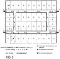
Figure 3 is a graph illustrating a system according to an embodiment of the invention in the first step, -
Figure 4 is a graph illustrating a system according to an embodiment of the invention in the second step, -
Figure 5 is a graph illustrating a system according to an embodiment of the invention in the first mode, -
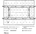
Figure 6 is a graph illustrating a system according to an embodiment of the invention in the first mode, in a second situation, -
Figure 7 is a graph illustrating a system according to an embodiment of the invention in the first mode, in a third situation, -
Figure 8 is a graph illustrating a system according to an embodiment of the invention in the second mode, -
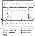
Figure 9 is a graph illustrating a system according to an embodiment of the invention in the second mode, in a second situation, and -
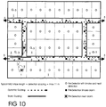
Figure 10 is a graph illustrating a system according to an embodiment of the invention in the second mode, in a third situation.
-
- In the invention, there are sequentially arranged light sources 40 (
Figure 1 a) , which are controlled in a way known as such, so that the sequentially arranged light sources form alight source string 4, which is installed in spaces that people use when exiting from a hazardous situation. These are for instance corridor spaces in hotels or other buildings or vessels, such as passenger ships. Thelight source string 4 or at least part thereof can be set in at least two modes. The first is a dynamic mode, where thelight sources 40 are switched on and off, so that there is created an illusion of movement. Now a person who sees the illusion of movement created by means of thelight sources 40 of the light source string is guided towards the proceeding direction of the "movement" of thelight source string 4. Typically the illusion of movement is achieved by controlling thelight sources 40 in groups, where the movement is created by switching on the next light source and respectively by switching off the previous one. The light sources are arranged/coupled in a string, particularly in aconductor string 41, where they are controlled in the way described above. Now there is achieved an illusion of movement by the light sources, i.e. by "trickling" the light, and said illusion of movement is created at least along part of the length of thelight source string 4, but typically along the whole length of the light source string. In the first mode, i.e. the dynamic mode, the "moving" light of thelight string 4 is typically created for example by groups of 3 light sources, where the light of one light source is switched on, and the rest of the two are switched off. The illusion of movement is obtained as the next light is switched on and the previous light is switched off. Thelight source strings 4 can be connected in succession, so that the illusion of movement can continue from one light source string to the next. When desired, the rate of the movement created by light can be adjusted, and the direction of the movement can also be changed. - The
light source string 4 or at least part of it also has a second mode, a static mode, where thelight sources 40 of the string or part of the string are illuminated. Typically the static, brighter illumination is created so that alllight sources 40 of at least onelight source string 4 or at least part of the light source string are switched to be illuminated simultaneously. The light source string is controlled to change modes between the dynamic and the static mode. The light source string can also have other modes. In a preferred embodiment, the color of the light emitted by the light source can be changed. -
Figure 1a illustrates alight source string 4. Thelight sources 40 can advantageously be for example light emitting diodes, LED light sources, which are fastened to aconductor string 41, for instance to a conductor string described in the patent publicationFl 108106 B control system 10, so that the control system receives signals fromseveral fire detectors 3 connected thereto. - In case of fire, many buildings or vessels are provided with
fire detectors 3. There are many different types of fire detectors. The regular types are smoke detectors, which send a signal to the control system when there is generated smoke that is typical of a fire. On the other hand, there are known temperature-sensitive detectors. In many cases, the employedfire detectors 3 are provided with both features, i.e. smoke detection and heat detection. This type of fire detector gives a signal of both smoke generation and of a temperature that surpasses a given predetermined value. In case of a fire, smoke is spread in a wide area, in which case the smoke detectors of several different fire detectors typically give an alarm, i.e. a signal. In a fire situation, a heat detector in turn only reacts when the fire has approached near the detector, i.e. it reacts to the fire in way that is more location-specific than with a smoke detector. There are also known flame detectors that give a signal after detecting a flame. The system according to the invention is arranged to function so that alight source string 4 or at least part thereof is activated in a situation where two or more fire detection signals have been received from adetector 3 arranged in alight source string 4 or part thereof. Now the activatedlight source string 4 is arranged to be first switched to a dynamic mode and to point in a suitable direction of anescape route 5, for example by changing the mode of thelight sources 40, for instance by "trickling" the light. -
Figures 1 - 10 illustrate in a simplified graph of the operation of a signaling, guiding and alert light system according to an embodiment of the invention, in connection with a cabin fire aboard a vessel. Thecabins 1 and thecorridor spaces 2 are provided withfire detectors 3, which include both smoke detection and heat detection functions. Thecorridor spaces 2 are provided with light source strings 4, which are represented in the activated mode inFigures 5 - 10. Figures 5 - 10 represent several light source strings 4 that can be controlled either separately and/or as a group. The light source strings 4 are typically arranged in succession, for example in the lower part of thecorridor space 2, typically on the floor. Thelight source string 4 can be fastened directly onto the mounting surface, or embedded therein. Thelight sources 40 can also be separately fastened to the mounting surface. - Consequently, in
Figure 1 , there is represented a part of the cabin department of the vessel, comprising a large number ofadjacent cabins 1 andcorridor spaces 2 of the cabin department. In the embodiment illustrated in the drawing, each cabin is provided with afire detector 3. Respectively, the corridor spaces are provided withfire detectors 3 spaced at suitable intervals. There are fourescape routes 5 from the cabin department, and the corridor spaces lead to said routes. The drawing depicts two elongate corridor spaces, as well as transversal corridor spaces arranged at regular intervals in perpendicular to said corridor spaces. The cabin department could also be for example part of a hotel or other building, for instance an office building, in which case the cabins would be room spaces. -
Figure 2 represents a situation where fire F has started in one of thecabins 1. In this situation, the cabin door has been left open. InFigure 3 , the smoke detector of thecabin fire detector 3 has reacted to the smoke generated by the fire and has given an alarm signal. InFigure 4 , the smoke generated by the fire has spread through the open door in thecorridor space 2 in the vicinity of the cabin. Now the smoke detector of thefire detector 3 located near the cabin in thecorridor space 2 has given an alarm signal. On the basis of these two signals, the light source strings 4 are switched, according toFigure 5 , to be activated to a dynamic mode, where they point to the escape routes by means of moving lights, for instance by "trickling" the lights, in a way that is programmed in advance. InFigure 5 , they point towards theescape routes 5. In the drawing, the light source strings 4 are represented in a simplified form, so that in the picture of thelight source string 4, an arrow points to the direction shown by thelight source string 4 in the first mode, i.e. the dynamic mode. In the embodiment ofFigure 5 , each of the elongate corridor spaces, where theescape routes 5 are located at the ends of the corridors, are provided with four light source strings 4, or the light source string comprises four sections. The transversal corridor spaces connecting the lengthwise light source strings each comprise two light source strings 4, or the light source string comprises two sections. In the embodiment ofFigure 5 , the light source strings are arranged to guide people evenly towards thedifferent escape routes 5. The guiding signal of the strings points in the opposite directions at roughly halfway of the length of the corridor spaces. Depending on the embodiment in question, the light source strings are in advance programmed to point in the desired direction as the system is activated. - Regrettably the fire continues and proceeds further, in which case, according to
Figure 6 , the temperature in thecabins 1 has risen, so that the temperature-sensitive detector 3' of the fire detector provided in thecabin 1 has given a signal. Smoke has spread in the corridor space, and thereseveral fire detectors 3 have given an alarm signal caused by detected smoke. The light source strings help people to find an escape route in the smoke-filled corridor space. - According to
Figure 7 , the temperature caused by the fire also rises outside the cabin, and the heat detector of the fire detector 3' placed in thecorridor space 2 outside the cabin gives an alarm signal. Now the light source string 4' located in thecorridor space 2 and allocated to the fire detector 3' is arranged to be switched to the static mode (Figure 8 ), where the light is not "trickling" anymore, but the luminosity of thelight source string 4 is increased by switching thelight sources 40 to emit constant light. This improves visibility in the smoke-filledcorridor space 2 in the vicinity of the site of fire. In addition, the light source strings 4 or light source string sections adjacent to the light source string 4' or part thereof that has been switched to the static mode are arranged to point in the exit direction, i.e. away from the site of fire or at least away from the light source string 4' that is in the static mode. - If the fire continues further, the heat detectors of possibly even several corridor space fire detectors 3' (
Figure 9 ) react, and on the basis of the signals given by them, more light source strings 4' or at least parts thereof are switched to the static mode (Figure 10 ), where at least the luminosity of the light emitted by them is increased by switching at least the major part of the light sources on. - Depending on the properties of the
light source 40, for example the color of the light emitted by the light source can be changed, when thelight source string 4 is switched to the static mode.Figure 10 represents two light source strings 4' in the static mode. With respect to these, the adjacent light source strings 4 are in the dynamic mode, indicating the direction of the escape route. - In the embodiment of the drawings, a
light source string 4 comprises sequentially arrangedlight sources 40. Thelight source string 4 can be divided into several sections, at least in length. The light sources in the light source string can be any suitable light sources, such as light emitting diodes, LED lights. - In the static mode the
light sources 40, typically all light sources in the light source string or part thereof, are in a mode where the light sources emit light. In color, the light can be different in the different modes of the light source string. - Typically the control of the
light sources 40 is arranged according to the signals received from thefire detectors 3. The control system or thecontrol device 10 controls thelight sources 40 in thelight source string 4. When necessary, the system can also be activated manually, and likewise deactivated. - Thus the invention relates to a method for controlling guiding, signal or alert lights, particularly the signal lights of emergency escape routes in a fire situation, in which method there are controlled sequentially arranged light sources, such as LED light sources. In the first step of the method, there are activated sequentially arranged
light sources 40, which are most advantageously arranged as alight source string 4 or at least part of a light source string, on the basis of a signal received from afire detector 3, to a first mode, in which first mode the sequentially arranged light sources are used for indicating the direction of an escape route, and/or to a second mode, where thelight sources 40 are switched to emit continuous light. - According to a preferred embodiment, in the second step the
light sources 40 of thelight source string 4, 4' or at least part thereof are switched from the first mode to a second mode, a static mode, where thelight sources 40 are switched to emit continuous light, on the basis of a heat detection or flame detection signal received from thefire detector 3. - According to the method, in order to activate the sequentially arranged
light sources 40, i.e. thelight source string 4, to a first mode there are needed at least two fire detection signals from the fire detectors, such as two smoke detection signals fromdifferent fire detectors 3 or a smoke detection signal and a heat or flame detection signal from one and the same fire detector. Sequentially arranged light sources, i.e. alight source string 4, 4' or at least part thereof, are switched to a second mode, a static mode, on the basis of a fire detection signal, particularly heat or flame detection signal, received from afire detector 3 connected thereto. - According to a preferred embodiment, a
light source string 4, 4' or at least part thereof is switched from the first mode to a second mode on the basis of a fire detection signal received from at least one fire detector connected thereto, said fire detector 3' being arranged in the same space with the light source string, particularly in acorridor space 2, advantageously in a section where thelight source string 4, 4' is located, or in the vicinity thereof. - According to a preferred embodiment, at least one fire detection signal is a heat detection signal, particularly from the
corridor space 2, from the fire detector 3'. - According to a preferred embodiment, the pointing direction of the
light source string 4 adjacent to the light source string 4' switched to the second mode, the static mode, saidlight source string 4 being preferably switched to the first mode, i.e. the dynamic mode, is adjusted to point away from the light source string 4' switched to the static mode. - According to a preferred embodiment, in targets with
several escape routes 5, the sequentially arranged light sources, i.e. light source strings 4, are in the first mode arranged to point to the nearest escape route and/or arranged to divide the people present in the target locations evenly between thedifferent escape routes 5. - According to a preferred embodiment, the
light source string 4 or at least part of the light source string is connected to receive a control signal from one or several fire detectors. - According to a preferred embodiment, the light sources employed in the method are LED light sources. The light sources can have several different modes. For example, it can be assumed that in the first, i.e. the dynamic mode, the light source has a first color that it emits. In the second mode, i.e. the static mode, the light source has a second color that it emits. In the second mode, the luminosity emitted by the light source string is higher than in the first mode, because all light sources of the
light source string 4, or part thereof, are advantageously switched to emit light in the second mode. - The invention also relates to a signaling, guiding or alert light system as defined by claim 8, particularly to a signal light system for emergency escape routes, said system comprising sequentially arranged light sources, such as LED light sources, and
fire detectors 3. Thelight sources 40, which are most advantageously arranged as alight source string 4 or at least as part of a light source string, are arranged to be switched to a first mode, i.e. a dynamic mode, where they are used for indicating the direction of the escape route, and/or to a second mode, where thelight sources 40 are switched to emit continuous light, on the basis of a fire detection signal received from afire detector 3. The sequentially arranged light sources, which are most advantageously arranged as alight source string 4 or at least as part of a light source string, also have at least one second mode, a static mode, where thelight sources 40 are switched to emit continuous light, on the basis of a heat detection or flame detection signal received from afire detector 3. The sequentially arranged light sources, i.e. alight source string 4, is arranged to be activated to the first mode, the dynamic mode, on the basis of at least two fire detection signals, such as smoke detection signals received from twodifferent fire detectors 3, or on the basis of smoke and heat detection or flame detection signals received from one and the same fire detector. The sequentially arranged light sources, i.e. alight source string 4, 4' or at least part thereof is arranged to be switched to the second mode, the static mode, on the basis of a least one fire detection signal, particularly heat or flame detection signal, received from afire detector 3 connected thereto. - According to a preferred embodiment, a
light source string 4, 4' or at least part thereof is arranged to be switched from the first mode to a second mode on the basis of at least one fire detection signal received from afire detector 3 connected thereto, said fire detector 3' being arranged in the same space with thelight source string 4, particularly in acorridor space 2, preferably in a section where thelight source string 4, 4' is located, or in the vicinity thereof. - According to a preferred embodiment, at least one fire detection signal is a heat or flame detection signal received from a fire detector 3' arranged in the
corridor space 2. - According to a preferred embodiment, the
fire detector 3 comprises means for giving a smoke and/or heat detection signal or a flame detection signal. - According to a preferred embodiment, the system is arranged to be connected to buildings, such as hotels, office buildings, residential buildings or the like, or to vessels, such as passenger ships.
- According to a preferred embodiment, the length of a section of sequentially arranged light sources, such as the length of the
light source string 4 or part thereof essentially corresponds to the distance left betweenseparate fire detectors 3, particularly in thecorridor space 2. - According to a preferred embodiment, adjacent to a
light source string 4 or part thereof or in the vicinity thereof, there is arranged afire detector 3, on the basis of the heat detection or flame detection signal whereof thelight source string 4 is arranged to be switched from the dynamic mode to the static mode. - The arrangement according to the invention is extremely advantageous and well suited to be used for example in hotels or passenger ships, as the signaling and guiding illumination for emergency escape routes, and as a system that speeds up evacuation procedures.
- Typically light source strings can also be used in other purposes than signaling and guiding passengers and/or pointing escape routes for example in hazardous situations.
- The light source string according to the invention can be based for example on a conductor string provided with LED light sources described in the patent publication
Fl 108106 B - The invention also relates to a device for a signaling, guiding or alert light system, particularly in a signal light system for emergency escape routes, said device comprising sequentially arranged light sources, such as LED light sources. The
light sources 40 are arranged as alight source string 4 or at least as part of a light source string, and the device comprises at least onefire detector 3, including both a smoke detector and a heat or flame detector, which are connected directly or through acontrol system 10 to the light source string or part thereof. - According to another embodiment, the invention relates to a device for a signaling, guiding or alert light system, particularly in a signal light system for emergency escape routes, said device comprising sequentially arranged light sources, such as LED light sources. The
light sources 40 are arranged as alight source string 4 or at least as part thereof, and the device comprises at least onefire detector 3, including both a smoke detector and a heat or flame detector, which are connected directly or through acontrol system 10 to the light source string or part thereof, so that thelight source string 4 or part thereof is provided with a fire detector allocated to it. - According to yet another embodiment, the invention relates to a device for a signaling, guiding or alert light system, particularly in a signal light system for emergency escape routes, said device comprising sequentially arranged light sources, such as LED light sources. The
light sources 40 are arranged as alight source string 4 or at least as part thereof, and the device comprises at least onefire detector 3, including both a smoke detector and a heat detector, which are connected directly or through acontrol system 10 to the light source string or part thereof, so that thefire detector 3 has onelight source string 4 or part thereof allocated to it. - The length of the light source string can be adjusted according to the needs of the target of application. In a preferred embodiment, the length of one light source string is adjusted to be the maximum operational diameter of the fire detector (or the maximum distance between adjacent fire detectors). In an embodiment, the distance between the fire detectors can be of the order 5 - 15 meters. advantageously 7 - 13 meters, preferably 9 - 11 meters. Now the string length is arranged respectively. Each
fire detector 3 located in the same space with alight source string 4 and affecting its modes is typically, but not necessarily, arranged in the center region of thelight source string 4, with respect to its lengthwise direction. - The light sources can also have other modes than the ones described above. For example, in a situation with disturbance or confusion, the light sources can be arranged to illuminate, in which case the light source string does not guide people, but the luminosity is maximal.
Claims (14)
- A method for controlling guiding, signal or alert lights, particularly the signal lights of an emergency escape route in a fire situation, in which method there are controlled sequentially arranged light sources, such as LED light sources, characterized in that in the method,
in the first step there are activated sequentially arranged light sources (40), which are arranged in a light source string (4) or at least as part of a light source string, on the basis of at least two fire detection signals from fire detectors, for instance two smoke detection signals from two separate fire detectors (3), or both a smoke detection signal and a heat or flame detection signal from one and the same fire detector, to a first mode, in which first mode the sequentially arranged light sources are used for indicating the direction of an escape route by the light sources being switched on and off so that there is created an illusion of movement, and
in the second step the light sources (40) of a light source string (4, 4') or at least part of it are switched from the first mode to a second mode, in which the light sources (40) are switched to emit continuous light,
wherein the light sources (40) of a light source string (4, 4') or at least part of it are switched from the first mode to the second mode on the basis of a heat detection or flame detection signal received from a fire detector (3) connected thereto. - A method according to any of the claims 1, characterized in that the light source string (4, 4') or at least part thereof is switched from the first mode to the second mode on the basis of a fire detection signal received from at least one fire detector connected thereto, said fire detector (3') being arranged in the same space with the light source string, particularly in a corridor space (2), preferably along a section where the light source string (4, 4') is located, or in the vicinity thereof.
- A method according to claims 1 or 2, characterized in that at least one fire detection signal is a heat or flame detection signal, received from a fire detector (3'), particularly from a corridor space (2).
- A method according to any of the claims 1 - 3, characterized in that the pointing direction of a light source string (4) that is adjacent to a light source string (4') switched to the second mode, the static mode, said light source string (4) being most suitably in the first mode, i.e. the dynamic mode, is arranged to point away from the light source string (4') that is in the static mode.
- A method according to any of the claims 1 - 4, characterized in that in targets with several escape routes (5), the sequentially arranged light sources i.e. light source strings (4) are in the first mode arranged to indicate the nearest escape route, and/or arranged to divide the people present in the target evenly towards the different escape routes (5).
- A method according to any of the claims 1 - 5, characterized in that the light source string (4) or at least part thereof is switched to receive a control signal from one or several fire detectors (3).
- A method according to any of the claims 1 - 6, characterized in that the light sources (40) employed in the method are LED light sources.
- A signaling, guiding or alert light system, particularly a signal light system for an emergency escape route, comprising sequentially arranged light sources, such as LED light sources, and fire detectors (3), characterized in that
the light sources (40), which are arranged as a light source string (4) or at least as part of a light source string, are arranged to be switched to a first mode on the basis of at least two fire detection signals from fire detectors, for instance two smoke detection signals from two separate fire detectors (3), or both a smoke detection signal and a heat or flame detection signal from one and the same fire detector, in which first mode the sequentially arranged light sources are arranged to indicate the direction of an escape route by the light sources being switched on and off so that there is created an illusion of movement, and
wherein the light sources (40) are arranged to be switched from the first mode to a second mode, in which the light sources (40) are switched to emit continuous light,
wherein the light sources (40) of a light source string (4, 4') or at least part of it are arranged to be switched from the first mode to a second mode on the basis of a heat detection or flame detection signal received from a fire detector (3) connected thereto. - A system according to claim 8, characterized in that a light source string (4, 4') or at least part thereof is arranged to be switched from the first mode to the second mode on the basis of at least one fire detection signal received from a fire detector (3) connected thereto, said fire detector (3') being arranged in the same space with the light source string (4), particularly in a corridor space (2), preferably along a section where the light source string (4, 4') is located, or in the vicinity thereof.
- A system according to claim 8 or 9, characterized in that at least one fire detection signal is a heat detection signal received from a fire detector (3') located in a corridor space (2).
- A system according to any of the claims 8 - 10, characterized in that the fire detector (3) comprises means for giving a smoke detection signal and/or a heat detection signal and/or a flame detection signal.
- A system according to any of the claims 8 - 11, characterized in that the system is arranged to be installed in buildings, such as hotels, office buildings, residential buildings or the like, or in vessels, such as passenger ships.
- A system according to any of the claims 8 - 12, characterized in that the length of a section of the sequentially arranged light sources, such as the length of a light source string (4) or part thereof, essentially corresponds to the distance left between individual fire detectors (3), particularly in a corridor space (2).
- A system according to claim 8, characterized in that next to a light source string (4) or part thereof, or in the vicinity thereof, there is arranged a fire detector (3), and that the light source string (3) is arranged to switch from the first mode to the second mode on the basis of a heat or flame detection signal received therefrom.
Priority Applications (2)
| Application Number | Priority Date | Filing Date | Title |
|---|---|---|---|
| PL09765959T PL2300103T3 (en) | 2008-06-19 | 2009-06-04 | Method and system for signaling, guiding and alerting |
| EP17170844.9A EP3222328B1 (en) | 2008-06-19 | 2009-06-04 | Method and system for signaling, guiding and alerting |
Applications Claiming Priority (2)
| Application Number | Priority Date | Filing Date | Title |
|---|---|---|---|
| FI20085621A FI122351B (en) | 2008-06-19 | 2008-06-19 | Procedure, system and device for display, guidance and warning |
| PCT/FI2009/050476 WO2009153393A1 (en) | 2008-06-19 | 2009-06-04 | Method, system and device for signaling, guiding and alerting |
Related Child Applications (2)
| Application Number | Title | Priority Date | Filing Date |
|---|---|---|---|
| EP17170844.9A Division EP3222328B1 (en) | 2008-06-19 | 2009-06-04 | Method and system for signaling, guiding and alerting |
| EP17170844.9A Division-Into EP3222328B1 (en) | 2008-06-19 | 2009-06-04 | Method and system for signaling, guiding and alerting |
Publications (3)
| Publication Number | Publication Date |
|---|---|
| EP2300103A1 EP2300103A1 (en) | 2011-03-30 |
| EP2300103A4 EP2300103A4 (en) | 2015-07-22 |
| EP2300103B1 true EP2300103B1 (en) | 2017-07-26 |
Family
ID=39589383
Family Applications (2)
| Application Number | Title | Priority Date | Filing Date |
|---|---|---|---|
| EP17170844.9A Active EP3222328B1 (en) | 2008-06-19 | 2009-06-04 | Method and system for signaling, guiding and alerting |
| EP09765959.3A Active EP2300103B1 (en) | 2008-06-19 | 2009-06-04 | Method and system for signaling, guiding and alerting |
Family Applications Before (1)
| Application Number | Title | Priority Date | Filing Date |
|---|---|---|---|
| EP17170844.9A Active EP3222328B1 (en) | 2008-06-19 | 2009-06-04 | Method and system for signaling, guiding and alerting |
Country Status (11)
| Country | Link |
|---|---|
| US (1) | US8717162B2 (en) |
| EP (2) | EP3222328B1 (en) |
| JP (1) | JP2011525021A (en) |
| KR (1) | KR101646286B1 (en) |
| AU (1) | AU2009259261B2 (en) |
| CA (1) | CA2724438C (en) |
| DK (1) | DK2300103T3 (en) |
| ES (2) | ES2954922T3 (en) |
| FI (1) | FI122351B (en) |
| PL (1) | PL2300103T3 (en) |
| WO (1) | WO2009153393A1 (en) |
Families Citing this family (15)
| Publication number | Priority date | Publication date | Assignee | Title |
|---|---|---|---|---|
| NL2002295C2 (en) * | 2008-12-05 | 2009-12-14 | Michel Robert Ten Wolde | Escape route illumination device for e.g. hotel, has lighting device mounted to wall at specific mounting height from floor, where lighting device illuminates predetermined area of floor |
| EP2643825B1 (en) * | 2010-11-22 | 2016-01-27 | Lumenox Limited | Emergency guidance display |
| DE102011103242B4 (en) | 2011-06-03 | 2018-10-18 | Marco Systemanalyse Und Entwicklung Gmbh | Intrinsically safe lamp |
| RU2617333C2 (en) | 2011-07-01 | 2017-04-24 | Филипс Лайтинг Холдинг Б.В. | Method of withdrawal person to reference site and light system comprising plurality of light sources, for use in such method |
| KR101357213B1 (en) * | 2012-02-07 | 2014-01-29 | 아이스파이프 주식회사 | Led illuminating apparatus for a parking lot and method for illuminating a parking lot using a led illuminating lamp |
| JP5850578B2 (en) * | 2013-07-23 | 2016-02-03 | 株式会社ティーエヌケー | Evacuation guidance system |
| US9824250B2 (en) * | 2013-11-04 | 2017-11-21 | Trimble Inc. | Location information within an area defined by a grid of radio-frequency tag circuits |
| JP5781144B2 (en) * | 2013-12-11 | 2015-09-16 | 株式会社ティーエヌケー | Guidance system |
| US9715800B2 (en) | 2015-04-01 | 2017-07-25 | International Business Machines Corporation | Lighting control for location finding |
| WO2017069788A1 (en) * | 2015-10-21 | 2017-04-27 | Kinkade Clifford | Fire safety visial aid |
| CA2929349A1 (en) * | 2016-04-29 | 2017-10-29 | Hubbell Incorporated | Light fixture |
| JP6486509B2 (en) * | 2018-01-09 | 2019-03-20 | ホーチキ株式会社 | Evacuation guidance system |
| US11037416B2 (en) | 2018-07-20 | 2021-06-15 | Comcast Cable Communications, Llc | Methods and systems for path lighting |
| CN111462441B (en) * | 2020-05-26 | 2022-05-06 | 合隆防爆电气有限公司 | Non-centralized low-voltage evacuation system with storage battery for lamp |
| CN111739238A (en) * | 2020-06-08 | 2020-10-02 | 珠海格力电器股份有限公司 | Dynamically-adjusted escape route generation method, system and device and fire detector |
Family Cites Families (25)
| Publication number | Priority date | Publication date | Assignee | Title |
|---|---|---|---|---|
| JPS5857795B2 (en) * | 1976-03-09 | 1983-12-21 | 三菱電機株式会社 | Dimming evacuation guide light |
| US4347499A (en) | 1981-01-02 | 1982-08-31 | Thomas F. Burkman, Sr. | Emergency guidance system |
| JPS61148596A (en) * | 1984-12-21 | 1986-07-07 | 株式会社竹中工務店 | Refuge guidance and survivor detector |
| GB2215105A (en) * | 1988-02-16 | 1989-09-13 | Richard William Henry Ford | Personnel evacuation system |
| JPH03238593A (en) * | 1990-02-15 | 1991-10-24 | Azusa Eng:Kk | Centralized control device for disaster preventing equipment |
| JP2745090B2 (en) * | 1992-03-21 | 1998-04-28 | ニッタン株式会社 | Display device and display control method |
| DK169931B1 (en) * | 1992-11-20 | 1995-04-03 | Scansafe International | Evacuation system |
| NO934463L (en) * | 1993-12-08 | 1995-06-09 | Jan Erik Vadseth | Lighting device with controllable light sources and light strip with such light sources |
| WO1996025729A1 (en) * | 1995-02-17 | 1996-08-22 | Rijlaarsdam Design Holding B.V. | Escape route indication system |
| JPH0991559A (en) * | 1995-09-20 | 1997-04-04 | Matsushita Electric Works Ltd | Heat and smoke hybrid type sensor |
| FI108106B (en) | 1996-11-25 | 2001-11-15 | Modular Technology Group Engin | A method for manufacturing a guide element and a guide element |
| JPH11200581A (en) * | 1998-01-16 | 1999-07-27 | Taisei Corp | Handrail |
| US6249221B1 (en) * | 1999-07-28 | 2001-06-19 | Joyce J. Reed | Emergency detector door illumination escape system |
| JP3924114B2 (en) * | 2000-06-26 | 2007-06-06 | 清水建設株式会社 | Stay limit state detection method |
| GB2370675B (en) | 2000-11-15 | 2003-04-30 | Maurice Bligh | Colour-coded evacuation signalling system |
| JP3917884B2 (en) * | 2002-04-03 | 2007-05-23 | 清水建設株式会社 | Stay limit state notification method |
| JP2004086566A (en) * | 2002-08-27 | 2004-03-18 | Matsushita Electric Works Ltd | Fire alarm for residence |
| DE10246033B4 (en) | 2002-10-02 | 2006-02-23 | Novar Gmbh | flight control system |
| WO2005079340A2 (en) | 2004-02-13 | 2005-09-01 | Lacasse Photoplastics, Inc. | Intelligent directional fire alarm system |
| US7255454B2 (en) * | 2004-06-24 | 2007-08-14 | Peterson John W | Emergency lighting system and method |
| JP4651322B2 (en) * | 2004-07-16 | 2011-03-16 | ホーチキ株式会社 | Fire alarm |
| US7026768B1 (en) * | 2004-08-04 | 2006-04-11 | Ruiz Carmelo C | Apparatus flashing lights in sequences indicating directions of movement in response to detected fire conditions and in response to an electrical power failure |
| US7218238B2 (en) | 2004-09-24 | 2007-05-15 | Edwards Systems Technology, Inc. | Fire alarm system with method of building occupant evacuation |
| US7800511B1 (en) * | 2006-03-07 | 2010-09-21 | Living Space International, Inc. | Emergency lighting system |
| JP5857795B2 (en) | 2011-05-17 | 2016-02-10 | 日産自動車株式会社 | Non-contact charger mounting structure |
-
2008
- 2008-06-19 FI FI20085621A patent/FI122351B/en active IP Right Grant
-
2009
- 2009-06-04 ES ES17170844T patent/ES2954922T3/en active Active
- 2009-06-04 DK DK09765959.3T patent/DK2300103T3/en active
- 2009-06-04 ES ES09765959.3T patent/ES2641594T3/en active Active
- 2009-06-04 EP EP17170844.9A patent/EP3222328B1/en active Active
- 2009-06-04 CA CA2724438A patent/CA2724438C/en active Active
- 2009-06-04 JP JP2011514073A patent/JP2011525021A/en active Pending
- 2009-06-04 KR KR1020117001086A patent/KR101646286B1/en active IP Right Grant
- 2009-06-04 US US12/999,882 patent/US8717162B2/en active Active
- 2009-06-04 AU AU2009259261A patent/AU2009259261B2/en active Active
- 2009-06-04 WO PCT/FI2009/050476 patent/WO2009153393A1/en active Application Filing
- 2009-06-04 PL PL09765959T patent/PL2300103T3/en unknown
- 2009-06-04 EP EP09765959.3A patent/EP2300103B1/en active Active
Non-Patent Citations (1)
| Title |
|---|
| None * |
Also Published As
| Publication number | Publication date |
|---|---|
| EP2300103A1 (en) | 2011-03-30 |
| EP3222328B1 (en) | 2023-08-09 |
| EP3222328A1 (en) | 2017-09-27 |
| KR20110033205A (en) | 2011-03-30 |
| CA2724438A1 (en) | 2009-12-23 |
| DK2300103T3 (en) | 2017-10-09 |
| US8717162B2 (en) | 2014-05-06 |
| EP3222328C0 (en) | 2023-08-09 |
| FI20085621A (en) | 2009-12-20 |
| ES2954922T3 (en) | 2023-11-27 |
| FI122351B (en) | 2011-12-15 |
| JP2011525021A (en) | 2011-09-08 |
| AU2009259261B2 (en) | 2014-04-24 |
| PL2300103T3 (en) | 2017-12-29 |
| AU2009259261A1 (en) | 2009-12-23 |
| ES2641594T3 (en) | 2017-11-10 |
| CA2724438C (en) | 2017-02-07 |
| WO2009153393A1 (en) | 2009-12-23 |
| EP2300103A4 (en) | 2015-07-22 |
| US20110089869A1 (en) | 2011-04-21 |
| FI20085621A0 (en) | 2008-06-19 |
| KR101646286B1 (en) | 2016-08-05 |
Similar Documents
| Publication | Publication Date | Title |
|---|---|---|
| EP2300103B1 (en) | Method and system for signaling, guiding and alerting | |
| US5815068A (en) | Guiding light system and lighting strip | |
| US7800511B1 (en) | Emergency lighting system | |
| NL2002295C2 (en) | Escape route illumination device for e.g. hotel, has lighting device mounted to wall at specific mounting height from floor, where lighting device illuminates predetermined area of floor | |
| US6998960B2 (en) | Method and apparatus for marking an escape route | |
| US5130909A (en) | Emergency lighting strip | |
| US7619538B1 (en) | Programmable, directing evacuation systems: apparatus and method | |
| US8083367B2 (en) | Emergency exit route illumination system and methods | |
| JP5667187B2 (en) | Light guidance system and control method thereof | |
| US20140132183A1 (en) | Method for guiding a human to a reference location, and lighting system comprising a plurality of light sources for use in such method | |
| CN102511201A (en) | Lighting system and method for controlling a lighting system | |
| GB2215105A (en) | Personnel evacuation system | |
| JP2007018240A (en) | Evacuation guide system | |
| GB2516073A (en) | Fire Safety Light | |
| GB2466656A (en) | Emergency exit guidance system employing electroluminescent wire | |
| WO2011029998A1 (en) | Illuminated sign and illuminated sign system | |
| EP2327062B1 (en) | Method and system for controlling, guiding and warning |
Legal Events
| Date | Code | Title | Description |
|---|---|---|---|
| PUAI | Public reference made under article 153(3) epc to a published international application that has entered the european phase |
Free format text: ORIGINAL CODE: 0009012 |
|
| 17P | Request for examination filed |
Effective date: 20101109 |
|
| AK | Designated contracting states |
Kind code of ref document: A1 Designated state(s): AT BE BG CH CY CZ DE DK EE ES FI FR GB GR HR HU IE IS IT LI LT LU LV MC MK MT NL NO PL PT RO SE SI SK TR |
|
| AX | Request for extension of the european patent |
Extension state: AL BA RS |
|
| DAX | Request for extension of the european patent (deleted) | ||
| RA4 | Supplementary search report drawn up and despatched (corrected) |
Effective date: 20150622 |
|
| RIC1 | Information provided on ipc code assigned before grant |
Ipc: A62B 3/00 20060101AFI20150616BHEP Ipc: F21S 4/00 20060101ALI20150616BHEP Ipc: G08B 5/36 20060101ALI20150616BHEP Ipc: G08B 7/06 20060101ALI20150616BHEP Ipc: G08B 17/00 20060101ALI20150616BHEP |
|
| 17Q | First examination report despatched |
Effective date: 20160127 |
|
| GRAP | Despatch of communication of intention to grant a patent |
Free format text: ORIGINAL CODE: EPIDOSNIGR1 |
|
| STAA | Information on the status of an ep patent application or granted ep patent |
Free format text: STATUS: GRANT OF PATENT IS INTENDED |
|
| INTG | Intention to grant announced |
Effective date: 20170316 |
|
| RIN1 | Information on inventor provided before grant (corrected) |
Inventor name: SUNDHOLM, GOERAN |
|
| GRAS | Grant fee paid |
Free format text: ORIGINAL CODE: EPIDOSNIGR3 |
|
| GRAA | (expected) grant |
Free format text: ORIGINAL CODE: 0009210 |
|
| STAA | Information on the status of an ep patent application or granted ep patent |
Free format text: STATUS: THE PATENT HAS BEEN GRANTED |
|
| AK | Designated contracting states |
Kind code of ref document: B1 Designated state(s): AT BE BG CH CY CZ DE DK EE ES FI FR GB GR HR HU IE IS IT LI LT LU LV MC MK MT NL NO PL PT RO SE SI SK TR |
|
| REG | Reference to a national code |
Ref country code: GB Ref legal event code: FG4D |
|
| REG | Reference to a national code |
Ref country code: CH Ref legal event code: EP |
|
| REG | Reference to a national code |
Ref country code: AT Ref legal event code: REF Ref document number: 911910 Country of ref document: AT Kind code of ref document: T Effective date: 20170815 |
|
| REG | Reference to a national code |
Ref country code: IE Ref legal event code: FG4D |
|
| REG | Reference to a national code |
Ref country code: DE Ref legal event code: R096 Ref document number: 602009047374 Country of ref document: DE |
|
| REG | Reference to a national code |
Ref country code: NL Ref legal event code: FP |
|
| REG | Reference to a national code |
Ref country code: DK Ref legal event code: T3 Effective date: 20171005 |
|
| REG | Reference to a national code |
Ref country code: SE Ref legal event code: TRGR |
|
| REG | Reference to a national code |
Ref country code: ES Ref legal event code: FG2A Ref document number: 2641594 Country of ref document: ES Kind code of ref document: T3 Effective date: 20171110 |
|
| REG | Reference to a national code |
Ref country code: NO Ref legal event code: T2 Effective date: 20170726 |
|
| REG | Reference to a national code |
Ref country code: LT Ref legal event code: MG4D |
|
| PG25 | Lapsed in a contracting state [announced via postgrant information from national office to epo] |
Ref country code: LT Free format text: LAPSE BECAUSE OF FAILURE TO SUBMIT A TRANSLATION OF THE DESCRIPTION OR TO PAY THE FEE WITHIN THE PRESCRIBED TIME-LIMIT Effective date: 20170726 Ref country code: HR Free format text: LAPSE BECAUSE OF FAILURE TO SUBMIT A TRANSLATION OF THE DESCRIPTION OR TO PAY THE FEE WITHIN THE PRESCRIBED TIME-LIMIT Effective date: 20170726 |
|
| PG25 | Lapsed in a contracting state [announced via postgrant information from national office to epo] |
Ref country code: BG Free format text: LAPSE BECAUSE OF FAILURE TO SUBMIT A TRANSLATION OF THE DESCRIPTION OR TO PAY THE FEE WITHIN THE PRESCRIBED TIME-LIMIT Effective date: 20171026 Ref country code: LV Free format text: LAPSE BECAUSE OF FAILURE TO SUBMIT A TRANSLATION OF THE DESCRIPTION OR TO PAY THE FEE WITHIN THE PRESCRIBED TIME-LIMIT Effective date: 20170726 Ref country code: GR Free format text: LAPSE BECAUSE OF FAILURE TO SUBMIT A TRANSLATION OF THE DESCRIPTION OR TO PAY THE FEE WITHIN THE PRESCRIBED TIME-LIMIT Effective date: 20171027 Ref country code: IS Free format text: LAPSE BECAUSE OF FAILURE TO SUBMIT A TRANSLATION OF THE DESCRIPTION OR TO PAY THE FEE WITHIN THE PRESCRIBED TIME-LIMIT Effective date: 20171126 |
|
| REG | Reference to a national code |
Ref country code: DE Ref legal event code: R026 Ref document number: 602009047374 Country of ref document: DE |
|
| PLBI | Opposition filed |
Free format text: ORIGINAL CODE: 0009260 |
|
| PG25 | Lapsed in a contracting state [announced via postgrant information from national office to epo] |
Ref country code: CZ Free format text: LAPSE BECAUSE OF FAILURE TO SUBMIT A TRANSLATION OF THE DESCRIPTION OR TO PAY THE FEE WITHIN THE PRESCRIBED TIME-LIMIT Effective date: 20170726 Ref country code: RO Free format text: LAPSE BECAUSE OF FAILURE TO SUBMIT A TRANSLATION OF THE DESCRIPTION OR TO PAY THE FEE WITHIN THE PRESCRIBED TIME-LIMIT Effective date: 20170726 |
|
| PLAX | Notice of opposition and request to file observation + time limit sent |
Free format text: ORIGINAL CODE: EPIDOSNOBS2 |
|
| 26 | Opposition filed |
Opponent name: HANNING & KAHL GMBH & CO. KG Effective date: 20180424 |
|
| PG25 | Lapsed in a contracting state [announced via postgrant information from national office to epo] |
Ref country code: SK Free format text: LAPSE BECAUSE OF FAILURE TO SUBMIT A TRANSLATION OF THE DESCRIPTION OR TO PAY THE FEE WITHIN THE PRESCRIBED TIME-LIMIT Effective date: 20170726 Ref country code: EE Free format text: LAPSE BECAUSE OF FAILURE TO SUBMIT A TRANSLATION OF THE DESCRIPTION OR TO PAY THE FEE WITHIN THE PRESCRIBED TIME-LIMIT Effective date: 20170726 |
|
| REG | Reference to a national code |
Ref country code: FR Ref legal event code: PLFP Year of fee payment: 10 |
|
| PG25 | Lapsed in a contracting state [announced via postgrant information from national office to epo] |
Ref country code: SI Free format text: LAPSE BECAUSE OF FAILURE TO SUBMIT A TRANSLATION OF THE DESCRIPTION OR TO PAY THE FEE WITHIN THE PRESCRIBED TIME-LIMIT Effective date: 20170726 |
|
| PLBB | Reply of patent proprietor to notice(s) of opposition received |
Free format text: ORIGINAL CODE: EPIDOSNOBS3 |
|
| REG | Reference to a national code |
Ref country code: BE Ref legal event code: MM Effective date: 20180630 |
|
| REG | Reference to a national code |
Ref country code: IE Ref legal event code: MM4A |
|
| PG25 | Lapsed in a contracting state [announced via postgrant information from national office to epo] |
Ref country code: LU Free format text: LAPSE BECAUSE OF NON-PAYMENT OF DUE FEES Effective date: 20180604 Ref country code: MC Free format text: LAPSE BECAUSE OF FAILURE TO SUBMIT A TRANSLATION OF THE DESCRIPTION OR TO PAY THE FEE WITHIN THE PRESCRIBED TIME-LIMIT Effective date: 20170726 |
|
| PG25 | Lapsed in a contracting state [announced via postgrant information from national office to epo] |
Ref country code: IE Free format text: LAPSE BECAUSE OF NON-PAYMENT OF DUE FEES Effective date: 20180604 |
|
| PG25 | Lapsed in a contracting state [announced via postgrant information from national office to epo] |
Ref country code: BE Free format text: LAPSE BECAUSE OF NON-PAYMENT OF DUE FEES Effective date: 20180630 |
|
| PG25 | Lapsed in a contracting state [announced via postgrant information from national office to epo] |
Ref country code: MT Free format text: LAPSE BECAUSE OF NON-PAYMENT OF DUE FEES Effective date: 20180604 |
|
| PLCK | Communication despatched that opposition was rejected |
Free format text: ORIGINAL CODE: EPIDOSNREJ1 |
|
| REG | Reference to a national code |
Ref country code: DE Ref legal event code: R100 Ref document number: 602009047374 Country of ref document: DE |
|
| REG | Reference to a national code |
Ref country code: AT Ref legal event code: UEP Ref document number: 911910 Country of ref document: AT Kind code of ref document: T Effective date: 20170726 |
|
| PG25 | Lapsed in a contracting state [announced via postgrant information from national office to epo] |
Ref country code: HU Free format text: LAPSE BECAUSE OF FAILURE TO SUBMIT A TRANSLATION OF THE DESCRIPTION OR TO PAY THE FEE WITHIN THE PRESCRIBED TIME-LIMIT; INVALID AB INITIO Effective date: 20090604 Ref country code: PT Free format text: LAPSE BECAUSE OF FAILURE TO SUBMIT A TRANSLATION OF THE DESCRIPTION OR TO PAY THE FEE WITHIN THE PRESCRIBED TIME-LIMIT Effective date: 20170726 |
|
| PG25 | Lapsed in a contracting state [announced via postgrant information from national office to epo] |
Ref country code: CY Free format text: LAPSE BECAUSE OF FAILURE TO SUBMIT A TRANSLATION OF THE DESCRIPTION OR TO PAY THE FEE WITHIN THE PRESCRIBED TIME-LIMIT Effective date: 20170726 Ref country code: MK Free format text: LAPSE BECAUSE OF NON-PAYMENT OF DUE FEES Effective date: 20170726 |
|
| PLBN | Opposition rejected |
Free format text: ORIGINAL CODE: 0009273 |
|
| STAA | Information on the status of an ep patent application or granted ep patent |
Free format text: STATUS: OPPOSITION REJECTED |
|
| 27O | Opposition rejected |
Effective date: 20200411 |
|
| PGFP | Annual fee paid to national office [announced via postgrant information from national office to epo] |
Ref country code: TR Payment date: 20220603 Year of fee payment: 14 Ref country code: PL Payment date: 20220602 Year of fee payment: 14 Ref country code: AT Payment date: 20220621 Year of fee payment: 14 |
|
| PGFP | Annual fee paid to national office [announced via postgrant information from national office to epo] |
Ref country code: CH Payment date: 20220701 Year of fee payment: 14 |
|
| P01 | Opt-out of the competence of the unified patent court (upc) registered |
Effective date: 20230614 |
|
| PGFP | Annual fee paid to national office [announced via postgrant information from national office to epo] |
Ref country code: NO Payment date: 20230622 Year of fee payment: 15 Ref country code: NL Payment date: 20230620 Year of fee payment: 15 Ref country code: FR Payment date: 20230620 Year of fee payment: 15 Ref country code: DK Payment date: 20230622 Year of fee payment: 15 Ref country code: DE Payment date: 20230620 Year of fee payment: 15 |
|
| PGFP | Annual fee paid to national office [announced via postgrant information from national office to epo] |
Ref country code: SE Payment date: 20230620 Year of fee payment: 15 Ref country code: FI Payment date: 20230621 Year of fee payment: 15 |
|
| PGFP | Annual fee paid to national office [announced via postgrant information from national office to epo] |
Ref country code: IT Payment date: 20230623 Year of fee payment: 15 Ref country code: GB Payment date: 20230622 Year of fee payment: 15 Ref country code: ES Payment date: 20230828 Year of fee payment: 15 |
|
| REG | Reference to a national code |
Ref country code: CH Ref legal event code: PL |
|
| REG | Reference to a national code |
Ref country code: AT Ref legal event code: MM01 Ref document number: 911910 Country of ref document: AT Kind code of ref document: T Effective date: 20230604 |
|
| PG25 | Lapsed in a contracting state [announced via postgrant information from national office to epo] |
Ref country code: AT Free format text: LAPSE BECAUSE OF NON-PAYMENT OF DUE FEES Effective date: 20230604 |
|
| PG25 | Lapsed in a contracting state [announced via postgrant information from national office to epo] |
Ref country code: AT Free format text: LAPSE BECAUSE OF NON-PAYMENT OF DUE FEES Effective date: 20230604 Ref country code: CH Free format text: LAPSE BECAUSE OF NON-PAYMENT OF DUE FEES Effective date: 20230630 |