EP2299526A1 - Fuel cell interconnector having excellent electrical conductivity, oxidation resistance, and low chromium volatility and method of manufacturing the same - Google Patents
Fuel cell interconnector having excellent electrical conductivity, oxidation resistance, and low chromium volatility and method of manufacturing the same Download PDFInfo
- Publication number
- EP2299526A1 EP2299526A1 EP10160115A EP10160115A EP2299526A1 EP 2299526 A1 EP2299526 A1 EP 2299526A1 EP 10160115 A EP10160115 A EP 10160115A EP 10160115 A EP10160115 A EP 10160115A EP 2299526 A1 EP2299526 A1 EP 2299526A1
- Authority
- EP
- European Patent Office
- Prior art keywords
- fuel cell
- electrical conductivity
- cell interconnector
- interconnector
- oxidation resistance
- Prior art date
- Legal status (The legal status is an assumption and is not a legal conclusion. Google has not performed a legal analysis and makes no representation as to the accuracy of the status listed.)
- Granted
Links
Images


Classifications
-
- H—ELECTRICITY
- H01—ELECTRIC ELEMENTS
- H01M—PROCESSES OR MEANS, e.g. BATTERIES, FOR THE DIRECT CONVERSION OF CHEMICAL ENERGY INTO ELECTRICAL ENERGY
- H01M8/00—Fuel cells; Manufacture thereof
- H01M8/02—Details
- H01M8/0202—Collectors; Separators, e.g. bipolar separators; Interconnectors
- H01M8/0204—Non-porous and characterised by the material
- H01M8/0206—Metals or alloys
- H01M8/0208—Alloys
- H01M8/021—Alloys based on iron
-
- H—ELECTRICITY
- H01—ELECTRIC ELEMENTS
- H01M—PROCESSES OR MEANS, e.g. BATTERIES, FOR THE DIRECT CONVERSION OF CHEMICAL ENERGY INTO ELECTRICAL ENERGY
- H01M8/00—Fuel cells; Manufacture thereof
- H01M8/02—Details
-
- H—ELECTRICITY
- H01—ELECTRIC ELEMENTS
- H01M—PROCESSES OR MEANS, e.g. BATTERIES, FOR THE DIRECT CONVERSION OF CHEMICAL ENERGY INTO ELECTRICAL ENERGY
- H01M8/00—Fuel cells; Manufacture thereof
- H01M8/02—Details
- H01M8/0202—Collectors; Separators, e.g. bipolar separators; Interconnectors
- H01M8/0204—Non-porous and characterised by the material
- H01M8/0223—Composites
- H01M8/0228—Composites in the form of layered or coated products
-
- H—ELECTRICITY
- H01—ELECTRIC ELEMENTS
- H01M—PROCESSES OR MEANS, e.g. BATTERIES, FOR THE DIRECT CONVERSION OF CHEMICAL ENERGY INTO ELECTRICAL ENERGY
- H01M8/00—Fuel cells; Manufacture thereof
- H01M8/04—Auxiliary arrangements, e.g. for control of pressure or for circulation of fluids
-
- Y—GENERAL TAGGING OF NEW TECHNOLOGICAL DEVELOPMENTS; GENERAL TAGGING OF CROSS-SECTIONAL TECHNOLOGIES SPANNING OVER SEVERAL SECTIONS OF THE IPC; TECHNICAL SUBJECTS COVERED BY FORMER USPC CROSS-REFERENCE ART COLLECTIONS [XRACs] AND DIGESTS
- Y02—TECHNOLOGIES OR APPLICATIONS FOR MITIGATION OR ADAPTATION AGAINST CLIMATE CHANGE
- Y02E—REDUCTION OF GREENHOUSE GAS [GHG] EMISSIONS, RELATED TO ENERGY GENERATION, TRANSMISSION OR DISTRIBUTION
- Y02E60/00—Enabling technologies; Technologies with a potential or indirect contribution to GHG emissions mitigation
- Y02E60/30—Hydrogen technology
- Y02E60/50—Fuel cells
-
- Y—GENERAL TAGGING OF NEW TECHNOLOGICAL DEVELOPMENTS; GENERAL TAGGING OF CROSS-SECTIONAL TECHNOLOGIES SPANNING OVER SEVERAL SECTIONS OF THE IPC; TECHNICAL SUBJECTS COVERED BY FORMER USPC CROSS-REFERENCE ART COLLECTIONS [XRACs] AND DIGESTS
- Y02—TECHNOLOGIES OR APPLICATIONS FOR MITIGATION OR ADAPTATION AGAINST CLIMATE CHANGE
- Y02P—CLIMATE CHANGE MITIGATION TECHNOLOGIES IN THE PRODUCTION OR PROCESSING OF GOODS
- Y02P70/00—Climate change mitigation technologies in the production process for final industrial or consumer products
- Y02P70/50—Manufacturing or production processes characterised by the final manufactured product
Landscapes
- Chemical & Material Sciences (AREA)
- Life Sciences & Earth Sciences (AREA)
- Engineering & Computer Science (AREA)
- Manufacturing & Machinery (AREA)
- Sustainable Development (AREA)
- Sustainable Energy (AREA)
- Chemical Kinetics & Catalysis (AREA)
- Electrochemistry (AREA)
- General Chemical & Material Sciences (AREA)
- Composite Materials (AREA)
- Fuel Cell (AREA)
Abstract
Description
- This application claims the priority of Korean Patent Application No.
10-2009-0088133 filed on September 17, 2009 - The present invention relates to a fuel cell interconnector, and more particularly, to a fuel cell interconnector that reduces chromium volatilization and increases electrical conductivity and oxidation resistance by promoting the formation of a spinel oxide layer through a surface-deformed layer, and a method of manufacturing the same.
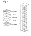
- As shown in
FIG. 1 , unit cells, each consisting of an anode, an electrolyte, and a cathode, and interconnectors connecting these unit cells are stacked upon one another to thereby form a fuel cell. - Among these components of the fuel cell, the interconnectors serve as both connectors interconnecting the individual unit cells to each other and separators separating the air from fuel being supplied from the fuel cell. Therefore, the interconnectors inside the fuel cell require high electrical conductivity, similar thermal expansion coefficients to those of the other parts of the fuel cell, oxidation resistance at operating temperature, particularly, at a high temperature of approximately 800°C, and economical efficiency.
- Graphite or ceramic materials, such as LaCrO3 doped with Cr-5Fe-Y2O3, have been widely used to form existing fuel cell interconnectors. However, these materials are currently being replaced with metallic materials due to formability and cost limitations.
- As for these metallic materials, which are taken into consideration to form fuel cell interconnectors, Cr-based compounds or high chromium (Cr) ferritic stainless steels are being considered. Representative examples of these Cr-based compounds or high Cr ferritic steels may include ZMG232L developed by Hitachi Metals and Crofer22 APU developed by ThyssenKrupp.
- Here, ZMG232L refers to a ferritic Fe-22 Cr alloy that contains 22% Cr and has 0.04% La and 0.22% Zr added thereto. The report says that ZMG232L has a thermal expansion coefficient of 12.8×10⁻⁶/°C and exhibits excellent oxidation resistance and electrical conductivity in a temperature range of 700 to 1000°C. It also says that these characteristics of ZMG232L are associated with the characteristics of oxides to be formed on the surface under oxidizing atmosphere. That is, as for the ZMG232L alloy, oxides to be formed on the surface have densely packed structures with high adhesion and excellent electrical conductivity.
- Meanwhile, Crofer22 APU, developed by ThyssenKrupp, refers to a ferritic Fe-Cr alloy, which was originally developed for an Auxiliary Power Unit (APU) on a vehicle. Here, Crofer22 APU contains a very small amount of 0.06% La in order to minimize chromium evaporation and reduce a thermal expansion coefficient. Mn and Ti are added thereto to thereby form an upper layer of (Mn,Cr)3O4 and a lower layer of Cr2O3 in an oxidizing atmosphere at high temperatures. Here, oxides (Mn,Cr)3O4 with a spinel structure reduce Cr evaporation.
- However, since the Cr-based alloys or high Cr ferritic stainless steels have high Cr contents, volatile Cr components are generated in the operating environment of fuel cells and prevent normal electro chemical reactions, resulting in poor cell performance. In addition, excellent electrical conductivity needs to be maintained for long periods of time at high temperatures. However, oxides to be formed on the surface thereof have insufficient stability, which causes an increase in the thickness of an oxide layer over time and thus a reduction in electrical conductivity.
- Recently, in order to solve these problems, technologies using surface treatments performed to control surface characteristics, particularly, the use of coatings, have started to make an appearance.
- Korean Patent Application Publication No.
2007-0041028 - In addition, Korean Patent Application Publication No.
2009-0068632 - An aspect of the present invention provides a fuel cell interconnector that reduces the chromium volatilization of the fuel cell interconnector and has excellent electrical conductivity and oxidation resistance, and a method of manufacturing the same.
- According to an aspect of the present invention, there is provided a fuel cell interconnector having excellent electrical conductivity, oxidation resistance, and low chromium volatility, including: a surface-deformed layer provided on a surface of a ferrite steel for a fuel cell interconnector and promoting formation of a Cr2MnO4 spinel oxide layer.
- According to another aspect of the present invention, there is provided a method of manufacturing a fuel cell interconnector having excellent electrical conductivity, oxidation resistance, and low chromium volatility, the method including: preparing a ferritic steel for a fuel cell interconnector; forming a surface-deformed layer on a surface of the ferritic steel; and forming a Cr2MnO4 spinel oxide layer by performing heat treatment at an operating temperature of a solid oxide fuel cell.
- The above and other aspects, features and other advantages of the present invention will be more clearly understood from the following detailed description taken in conjunction with the accompanying drawings, in which:
-
FIG. 1 is a schematic view illustrating a fuel cell and unit cells thereof; -
FIG. 2A depicts a graph illustrating the results of performing Auger electron spectroscopic analysis of a comparative example; -
FIG. 2B depicts a graph illustrating the results of performing Auger electron spectroscopic analysis of an inventive example 1; -
FIG. 2C depicts a graph illustrating the results of performing Auger electron spectroscopic analysis of an inventive example 2; -
FIG. 3 is a photograph obtained by observing a surface area of the inventive example 1; -
FIG. 4 is a HR image analysis photograph of the inventive example 1; -
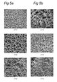
FIG. 5A shows SEM photographs according to a crystal surface of the comparative example; -
FIG. 5B shows SEM photographs according to a crystal surface of the inventive example 1; -
FIG. 6 depicts a graph illustrating results of measuring Cr volatility rates over time of the comparative example and the inventive examples 1 and 2; -
FIG. 7 depicts a graph illustrating results of measuring the Area Specific Resistances (ASR) of the comparative example and the inventive example 1; and -
FIG. 8 is a graph illustrating the results of measuring the mass gain of sample with time in order to check the oxidation resistance of each of the comparative example and the inventive example 1. - Exemplary embodiments of the present invention will now be described in detail with reference to the accompanying drawings.
- The present inventors have reached the present invention, finding that the diffusion of materials can be controlled by forming deformed layers on the surfaces of interconnectors of a fuel cell in the related art to thereby control oxide layers to be formed on the surfaces, so that electrical conductivity and oxidation resistance can be increased through ideal oxide layers.
- A method of manufacturing a fuel cell interconnector will now be described in detail.
- A method of manufacturing a fuel cell interconnector according to an exemplary embodiment of the invention includes preparing a ferritic steel for a fuel cell interconnector, forming a surface-deformed layer on the surface of the ferritic steel, and promoting the formation of a Cr2MnO4 spinel oxide layer by heat treatment at the operating temperature of a solid oxide fuel cell.
- The ferritic steel for a fuel cell interconnector is a high Cr ferritic steel, and preferably, a Fe-Mn-Cr ferritic stainless steel. However, any known materials to form fuel cell interconnectors can also be used therefor.
- According to this embodiment, a surface-deformed layer is formed on the surface of the ferritic steel. Here, in order to form the surface-deformed layer, various kinds of methods may be used. For example, the surface-deformed layer may be form by ion implantation, shot pinning, radio frequency processing, or skin pass rolling.
- When ion implantation is performed, pressure within an ion implantation chamber may be maintained at less than 5x10⁻⁶ Torr.
- Further, before carrying out ion implantation, an inert gas, such as Ar, is injected at a pressure of up to 2x10⁻³ Torr, and plasma is then generated at 800V DC to thereby perform a plasma cleaning process of the steel surface. Here, the plasma cleaning process may last 30 minutes or longer.
- As for the above-described ion implantation, carbon ions or nitrogen ions may be used. Methane (CH4) gas may be used for carbon ion implantation, and nitrogen (N2) gas may be used for nitrogen ion implantation.
- According to this embodiment of the invention, a deformed layer having a deformed structure is formed on the surface of a Fe-Cr ferritic steel to be used for an interconnector. Here, the deformed structure may include a nano-crystal structure or an amorphous structure. This nano-crystal structure or amorphous structure is formed through potential integration caused by deformation. The deformed layer having this structure provides a shorter diffusion path than a general fine polycrystalline structure, thereby promoting the diffusion of Mn.
- When a fuel cell is operated without forming a surface-deformed layer in the related art, chromium (Cr) is volatilized because Cr2O3 is mainly formed on the surface of an interconnector. However, in this invention, by forming the surface-deformed layer, the diffusion of Mn is promoted when the fuel cell is operated, thereby relatively reducing the Cr content and promoting the formation of a spinel oxide layer corresponding to Cr2MnO4.
- After the surface-deformed layer is formed, heat treatment is performed in a temperature range of 500 to 900°C to thereby form an oxide layer. The temperature range corresponds to the operating temperature of the fuel cell. As formation of the Cr2MnO4 spinel oxide layer is promoted by performing the heat treatment, Cr volatility is reduced, and the electrical conductivity and the oxidation resistance of the fuel cell are increased.
- Hereinafter, an interconnector of the fuel cell according to an exemplary embodiment of the invention will be described in detail.
- A Cr2MnO4 spinel oxide layer is uniformly formed on the surface of the fuel cell interconnector according to this embodiment through the surface-deformed layer from the beginning of the operation of the fuel cell. In the related art, Cr2O3 oxides are mostly formed initially when the operating temperature of the fuel cell is reached, and a Cr2MnO4 spinel oxide layer is formed after a period of time has elapsed. However, in this invention, after the deformed structure is formed, heat treatment is performed at the operating temperature of the fuel cell to thereby obtain a fuel cell interconnector in which a Cr2MnO4 spinel oxide layer is formed from the beginning.
- The Cr2MnO4 spinel oxide layer is formed, on a surface area of the interconnector, in the form of surface oxide particles having a larger size than the Cr2O3 oxides. With time, the entire surface area is covered with the Cr2MnO4 spinel oxide layer.
- Hereinafter, exemplary embodiments of the invention will be described in detail. However, the invention is not limited to the exemplary embodiments of the invention to be described below.
- As for test specimens, steel sheets Crofer22APU, which are manufactured by TKS and have recently come to prominence as fuel cell interconnectors, were used. The Crofer22APU steel sheet includes, by weight%: 22.78% Cr, 0.02% Si, 0.44% Mn, 0.07% Ti, 0.004% C, 0.01% Cu, 0.05% P, 0.0086% La, and the balance of Fe and unavoidable impurities.
- A surface-deformed layer was formed on the test specimens by ion implantation. Here, ion implantation was conducted under the following conditions.
- The pressure within an ion implantation chamber is maintained at 5x10⁻⁶ Torr or less.
- In addition, before performing ion implantation, Ar is injected at a pressure of up to 2x10⁻³ Torr, and plasma is generated at 800V DC to thereby perform a plasma cleaning process of the surface for 30 minutes or longer.
- RF plasma was generated at a power of 200W by using methane (CH4) gas for carbon ion implantation and nitrogen (N2) gas for nitrogen ion implantation, thereby performing ion implantation. The detailed conditions therefor are shown in Table 1.
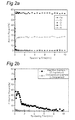
[Table 1] Pressure during gas injection (10-3 Torr) Bias (kV) Ion implantation time (min) RF plasma power (W) Frequency (Hz) Pulse width (µ sec) Expected ion dose (cm-2) Carbon implantation (CH4 gas) 2 -60 9 200 100 30 5x10¹⁶ Nitrogen implantation (N2 gas) 2 -60 15 200 100 30 5x10¹⁶ - After performing carbon (C) ion and nitrogen (N) ion implantation using the above-described method, Auger electron spectroscopic analysis was performed by milling the test specimens in a thickness direction, and the results thereof are shown in
FIGS. 2A to 2C . The result, as shown inFIG. 2A , corresponds to an unimplantated comparative example, the result, shown inFIG. 2B , corresponds to a carbon (C) ion implanted inventive example 1, and the result, shown inFIG. 2C , corresponds to an nitrogen (N) ion implanted inventive example 2. - For Auger electron spectroscopic analysis, samples are milled at a rate of approximately 150Å per minute. As shown in
FIGS. 2B and2C , the ion-implantation-affected zone is approximately 100nm. The zone from 15 to 30 has the largest amount of ions being implanted. This zone coincides with an area where a fine amorphous structure is formed, the area observed inFIG. 4 . -
FIG. 3 is a photograph showing a surface area of the inventive example 1. As shown inFIG. 3 , when C ion implantation is performed, a deformed structure having a thickness of 400 nm in parallel with the surface layer is formed. It can be seen that a nano-crystal structure and an amorphous structure are formed on the outermost surface through HR image analysis as shown inFIG. 4 . -
FIGS. 5A and 5B are SEM photographs according to the surface crystal planes on the surface areas of the comparative example and the inventive example 1, respectively. From the SEM photographs, shown inFIGS. 5A and 5B , the shapes of oxides are compared when oxidation is carried out after ion implantation. As shown inFIGS. 5A and 5B , as compared to the comparative example, the shapes of oxides were changed when oxidation was carried out after C ion implantation in the inventive example 1. That is, triangular oxides were observed in the (111) plane, while fine oxides were observed in the (110) and (100) planes. -
FIG. 6 depicts a graph illustrating the results of measuring Cr volatility rates over time with respect to the comparative example and the inventive examples 1 and 2. As shown in the graph ofFIG. 6 , Cr volatility was reduced to approximately one third when C or N ions were implanted. - Furthermore, in order to check an increase in electrical conductivity, the Area Specific resistances (ASR) of the comparative example and the inventive example 1 were measured, and the measured results thereof are shown in
FIG. 7 . As shown inFIG. 7 , the C ion implanted inventive example 1 had a low ASR, which showed that electrical conductivity was increased. - In order to check the oxidation of each the comparative example and the inventive example 1, mass gain of sample over time was measured, and the measured results are shown in
FIG. 8 . As shown inFIG. 8 , the excellent oxidation resistance of the inventive example 1 was maintained even after 500 hours of operation. - As set forth above, according to exemplary embodiments of the invention, the amount of Cr to be volatilized from a fuel cell interconnector is significantly reduced, electrical conductivity is increased, and oxidation resistance is increased, thereby markedly improving the performance of the entire fuel cell.
- Specific embodiments are described hereafter, with nummer only for reference purposes.
- A method embodiment 1 of manufacturing a fuel cell interconnector having excellent electrical conductivity, oxidation resistance, and low chromium volatility, the method comprising:
- preparing a ferritic steel for a fuel cell interconnector;
- forming a surface-deformed layer on a surface of the ferritic steel; and
- forming a Cr2MnO4 spinel oxide layer by performing heat treatment at an operating temperature of a solid oxide fuel cell.
- The method of method embodiment 1, wherein the surface-deformed layer comprises a nano-crystal structure or an amorphous structure.
- The method of method embodiment 1, wherein the surface-deformed layer comprises an amorphous structure
- The method of any one of method embodiment 1-3, wherein the surface-deformed layer is formed by any one of ion implantation, shot pinning, radio frequency processing, and skin pass rolling.
- The method of any one of method embodiments 1-4, wherein the operating temperature is within a range of 500 to 900°C.
- A fuel cell interconnector embodiment 1 having excellent electrical conductivity, oxidation resistance, and low chromium volatility, comprising: a surface-deformed layer provided on a surface of a ferritic steel for a fuel cell interconnector and promoting formation of a Cr2Mn04 spinel oxide layer.
- The fuel cell interconnector of the fuel cell interconnector embodiment 1, wherein the Cr2MnO4 spinel oxide layer is uniformly provided on a surface of the fuel cell interconnector from the beginning of an operation of a fuel cell.
- While the present invention has been shown and described in connection with the exemplary embodiments, it will be apparent to those skilled in the art that modifications and variations can be made without departing from the spirit and scope of the invention as defined by the appended claims.
Claims (7)
- A method of manufacturing a fuel cell interconnector having excellent electrical conductivity, oxidation resistance, and low chromium volatility, the method comprising:preparing a ferritic steel for a fuel cell interconnector;forming a surface-deformed layer on a surface of the ferritic steel; andforming a Cr2MnO4 spinel oxide layer by performing heat treatment at an operating temperature of a solid oxide fuel cell.
- The method of claim 1, wherein the surface-deformed layer comprises a nano-crystal structure.
- The method of claim 1, wherein the surface-deformed layer comprises an amorphous structure
- The method of any one of claims 1-3, wherein the surface-deformed layer is formed by any one of ion implantation, shot pinning, radio frequency processing, and skin pass rolling.
- The method of any one of claims 1-4, wherein the operating temperature is within a range of 500 to 900°C.
- A fuel cell interconnector having excellent electrical conductivity, oxidation resistance, and low chromium volatility, comprising:a surface-deformed layer provided on a surface of a ferritic steel for a fuel cell interconnector and promoting formation of a Cr2MnO4 spinel oxide layer.
- The fuel cell interconnector of claim 6, wherein the Cr2MnO4 spinel oxide layer is uniformly provided on a surface of the fuel cell interconnector from the beginning of an operation of a fuel cell.
Applications Claiming Priority (1)
| Application Number | Priority Date | Filing Date | Title |
|---|---|---|---|
| KR1020090088133A KR101042249B1 (en) | 2009-09-17 | 2009-09-17 | Fuel cell interconnector having excellent electrical conductivity, oxidation resistance and low chromium volatility and method for manufacturing the same |
Publications (2)
| Publication Number | Publication Date |
|---|---|
| EP2299526A1 true EP2299526A1 (en) | 2011-03-23 |
| EP2299526B1 EP2299526B1 (en) | 2013-06-12 |
Family
ID=42543259
Family Applications (1)
| Application Number | Title | Priority Date | Filing Date |
|---|---|---|---|
| EP10160115.1A Not-in-force EP2299526B1 (en) | 2009-09-17 | 2010-04-16 | Fuel cell interconnector having excellent electrical conductivity, oxidation resistance, and low chromium volatility and method of manufacturing the same |
Country Status (3)
| Country | Link |
|---|---|
| EP (1) | EP2299526B1 (en) |
| KR (1) | KR101042249B1 (en) |
| DK (1) | DK2299526T3 (en) |
Cited By (3)
| Publication number | Priority date | Publication date | Assignee | Title |
|---|---|---|---|---|
| WO2014046763A1 (en) * | 2012-09-24 | 2014-03-27 | Battelle Memorial Institute | Surface modification to prevent oxide scale spallation |
| JP5996137B1 (en) * | 2016-03-17 | 2016-09-21 | 大阪瓦斯株式会社 | Inter-cell connecting member and solid oxide fuel cell |
| EP3239342A4 (en) * | 2014-12-26 | 2018-05-16 | Posco | Austenitic-based stainless steel for fuel cell |
Families Citing this family (1)
| Publication number | Priority date | Publication date | Assignee | Title |
|---|---|---|---|---|
| KR101959380B1 (en) | 2017-03-17 | 2019-03-19 | 한국과학기술연구원 | Ferritic stainless steel with high oxidation resistance and fuel cell interconnector using the same and fuel cell |
Citations (6)
| Publication number | Priority date | Publication date | Assignee | Title |
|---|---|---|---|---|
| US20060286432A1 (en) * | 2005-06-15 | 2006-12-21 | Rakowski James M | Interconnects for solid oxide fuel cells and ferritic stainless steels adapted for use with solid oxide fuel cells |
| US20070077481A1 (en) * | 2005-09-30 | 2007-04-05 | Chatterjee Dilip K | Metallic structures for solid oxide fuel cells |
| KR20070041028A (en) | 2005-10-13 | 2007-04-18 | 재단법인 포항산업과학연구원 | Method of coating on fe-cr alloy for sofe interconnect |
| US7390582B2 (en) * | 2003-02-18 | 2008-06-24 | Forschungszentrum Julich Gmbh | Method for producing a protective coating for substrates that are subjected to high temperatures and form chromium oxide |
| KR100887831B1 (en) * | 2007-11-14 | 2009-03-09 | 현대자동차주식회사 | Surface reforming method of metal bipolar plate for fuel cell |
| KR20090068632A (en) | 2007-12-24 | 2009-06-29 | 주식회사 포스코 | A fabrication method of separators for planar solid oxide fuel cells |
Family Cites Families (2)
| Publication number | Priority date | Publication date | Assignee | Title |
|---|---|---|---|---|
| DE10025108A1 (en) | 2000-05-20 | 2001-11-29 | Forschungszentrum Juelich Gmbh | High temperature material |
| DE102006007598A1 (en) * | 2006-02-18 | 2007-08-30 | Forschungszentrum Jülich GmbH | Creep resistant ferritic steel |
-
2009
- 2009-09-17 KR KR1020090088133A patent/KR101042249B1/en active IP Right Grant
-
2010
- 2010-04-16 EP EP10160115.1A patent/EP2299526B1/en not_active Not-in-force
- 2010-04-16 DK DK10160115.1T patent/DK2299526T3/en active
Patent Citations (6)
| Publication number | Priority date | Publication date | Assignee | Title |
|---|---|---|---|---|
| US7390582B2 (en) * | 2003-02-18 | 2008-06-24 | Forschungszentrum Julich Gmbh | Method for producing a protective coating for substrates that are subjected to high temperatures and form chromium oxide |
| US20060286432A1 (en) * | 2005-06-15 | 2006-12-21 | Rakowski James M | Interconnects for solid oxide fuel cells and ferritic stainless steels adapted for use with solid oxide fuel cells |
| US20070077481A1 (en) * | 2005-09-30 | 2007-04-05 | Chatterjee Dilip K | Metallic structures for solid oxide fuel cells |
| KR20070041028A (en) | 2005-10-13 | 2007-04-18 | 재단법인 포항산업과학연구원 | Method of coating on fe-cr alloy for sofe interconnect |
| KR100887831B1 (en) * | 2007-11-14 | 2009-03-09 | 현대자동차주식회사 | Surface reforming method of metal bipolar plate for fuel cell |
| KR20090068632A (en) | 2007-12-24 | 2009-06-29 | 주식회사 포스코 | A fabrication method of separators for planar solid oxide fuel cells |
Cited By (5)
| Publication number | Priority date | Publication date | Assignee | Title |
|---|---|---|---|---|
| WO2014046763A1 (en) * | 2012-09-24 | 2014-03-27 | Battelle Memorial Institute | Surface modification to prevent oxide scale spallation |
| EP3239342A4 (en) * | 2014-12-26 | 2018-05-16 | Posco | Austenitic-based stainless steel for fuel cell |
| US10494707B2 (en) | 2014-12-26 | 2019-12-03 | Posco | Austenitic-based stainless steel for molten carbonate fuel cell |
| JP5996137B1 (en) * | 2016-03-17 | 2016-09-21 | 大阪瓦斯株式会社 | Inter-cell connecting member and solid oxide fuel cell |
| JP2017168358A (en) * | 2016-03-17 | 2017-09-21 | 大阪瓦斯株式会社 | Intercellular connection member and cell for solid oxide fuel cell |
Also Published As
| Publication number | Publication date |
|---|---|
| KR20110030141A (en) | 2011-03-23 |
| EP2299526B1 (en) | 2013-06-12 |
| DK2299526T3 (en) | 2013-09-16 |
| KR101042249B1 (en) | 2011-06-17 |
Similar Documents
| Publication | Publication Date | Title |
|---|---|---|
| EP2068389B1 (en) | Method for producing separator for fuel cell, separator for fuel cell, and fuel cell | |
| JP5133695B2 (en) | Fuel cell components | |
| EP2597710B1 (en) | Polymer electrolyte fuel cell comprising titanium separator | |
| EP2112250B1 (en) | Stainless separator for fuel cell and method of manufacturing the same | |
| KR101728248B1 (en) | Fuel cell separator | |
| KR101548064B1 (en) | Fuel cell separator | |
| EP1990855A1 (en) | Separator for solid polymer fuel cell and method for manufacturing the same | |
| EP1600520B1 (en) | Heat-resistant steel | |
| EP2104169A1 (en) | Alloy coating film for metal separator of fuel cell, method for producing the same, sputtering target material, metal separator and fuel cell | |
| EP2136427A1 (en) | Fuel Cell Interconnect Structures, And Related Devices And Processes | |
| WO2017169712A1 (en) | Titanium alloy material, separator, cell and fuel cell | |
| EP2031687A1 (en) | Pure titanium or titanium alloy separator for solid polymer fuel cell and method for producing the same | |
| EP2299526B1 (en) | Fuel cell interconnector having excellent electrical conductivity, oxidation resistance, and low chromium volatility and method of manufacturing the same | |
| JP6414369B1 (en) | Base material stainless steel plate for steel plate for fuel cell separator and method for producing the same | |
| EP3267521B1 (en) | Titanium material, separator, solid high-polymer fuel cell, and titanium-material manufacturing method | |
| EP1735865B1 (en) | Fuel cell separator, fuel cell stack, fuel cell vehicle, and method of manufacturing the fuel cell separator | |
| KR102298876B1 (en) | Separator for fuel cell and coating method of separator for fuel cell | |
| WO2018084184A1 (en) | Titanium material, constituent member for cells, cell, and solid polymer fuel cell | |
| JP2015069692A (en) | Fuel battery separator, and method for hydrophilic treatment thereof | |
| JP4854992B2 (en) | Separator for polymer electrolyte fuel cell and method for producing the same | |
| KR101356954B1 (en) | Stainless steel for polymer electrolyte membrane fuel cell separator and the method of manufacturing the same | |
| JP2017088955A (en) | Titanium material for separator of solid polymer form fuel cell and separator using the same | |
| KR101027222B1 (en) | OAE/Co Coating for Planar Solid Oxide Fuel Cell Interconnects | |
| KR100867819B1 (en) | Surface layer of metal bipolar plate for fuel cell and method for creating the same | |
| CN110212211B (en) | Stainless steel base material |
Legal Events
| Date | Code | Title | Description |
|---|---|---|---|
| PUAI | Public reference made under article 153(3) epc to a published international application that has entered the european phase |
Free format text: ORIGINAL CODE: 0009012 |
|
| AK | Designated contracting states |
Kind code of ref document: A1 Designated state(s): AT BE BG CH CY CZ DE DK EE ES FI FR GB GR HR HU IE IS IT LI LT LU LV MC MK MT NL NO PL PT RO SE SI SK SM TR |
|
| 17P | Request for examination filed |
Effective date: 20110914 |
|
| 17Q | First examination report despatched |
Effective date: 20111116 |
|
| GRAP | Despatch of communication of intention to grant a patent |
Free format text: ORIGINAL CODE: EPIDOSNIGR1 |
|
| RIN1 | Information on inventor provided before grant (corrected) |
Inventor name: KIM, HAE RYOUNG Inventor name: HAN, SEUNG HEE Inventor name: SUH, JIN YOO Inventor name: LEE, YOUNG SU Inventor name: SHIM, JAE HYEOK Inventor name: HONG, SEUNG HEE Inventor name: JUNG, WOO SANG Inventor name: CHO, YOUNG WHAN Inventor name: KIM, DONG IK |
|
| GRAS | Grant fee paid |
Free format text: ORIGINAL CODE: EPIDOSNIGR3 |
|
| GRAA | (expected) grant |
Free format text: ORIGINAL CODE: 0009210 |
|
| AK | Designated contracting states |
Kind code of ref document: B1 Designated state(s): AT BE BG CH CY CZ DE DK EE ES FI FR GB GR HR HU IE IS IT LI LT LU LV MC MK MT NL NO PL PT RO SE SI SK SM TR |
|
| REG | Reference to a national code |
Ref country code: GB Ref legal event code: FG4D |
|
| REG | Reference to a national code |
Ref country code: CH Ref legal event code: EP |
|
| REG | Reference to a national code |
Ref country code: AT Ref legal event code: REF Ref document number: 616973 Country of ref document: AT Kind code of ref document: T Effective date: 20130615 |
|
| REG | Reference to a national code |
Ref country code: IE Ref legal event code: FG4D |
|
| REG | Reference to a national code |
Ref country code: DE Ref legal event code: R096 Ref document number: 602010007749 Country of ref document: DE Effective date: 20130808 |
|
| REG | Reference to a national code |
Ref country code: DK Ref legal event code: T3 |
|
| PG25 | Lapsed in a contracting state [announced via postgrant information from national office to epo] |
Ref country code: SE Free format text: LAPSE BECAUSE OF FAILURE TO SUBMIT A TRANSLATION OF THE DESCRIPTION OR TO PAY THE FEE WITHIN THE PRESCRIBED TIME-LIMIT Effective date: 20130612 Ref country code: GR Free format text: LAPSE BECAUSE OF FAILURE TO SUBMIT A TRANSLATION OF THE DESCRIPTION OR TO PAY THE FEE WITHIN THE PRESCRIBED TIME-LIMIT Effective date: 20130913 Ref country code: FI Free format text: LAPSE BECAUSE OF FAILURE TO SUBMIT A TRANSLATION OF THE DESCRIPTION OR TO PAY THE FEE WITHIN THE PRESCRIBED TIME-LIMIT Effective date: 20130612 Ref country code: LT Free format text: LAPSE BECAUSE OF FAILURE TO SUBMIT A TRANSLATION OF THE DESCRIPTION OR TO PAY THE FEE WITHIN THE PRESCRIBED TIME-LIMIT Effective date: 20130612 Ref country code: SI Free format text: LAPSE BECAUSE OF FAILURE TO SUBMIT A TRANSLATION OF THE DESCRIPTION OR TO PAY THE FEE WITHIN THE PRESCRIBED TIME-LIMIT Effective date: 20130612 Ref country code: ES Free format text: LAPSE BECAUSE OF FAILURE TO SUBMIT A TRANSLATION OF THE DESCRIPTION OR TO PAY THE FEE WITHIN THE PRESCRIBED TIME-LIMIT Effective date: 20130923 Ref country code: NO Free format text: LAPSE BECAUSE OF FAILURE TO SUBMIT A TRANSLATION OF THE DESCRIPTION OR TO PAY THE FEE WITHIN THE PRESCRIBED TIME-LIMIT Effective date: 20130912 |
|
| REG | Reference to a national code |
Ref country code: AT Ref legal event code: MK05 Ref document number: 616973 Country of ref document: AT Kind code of ref document: T Effective date: 20130612 |
|
| REG | Reference to a national code |
Ref country code: NL Ref legal event code: VDEP Effective date: 20130612 |
|
| REG | Reference to a national code |
Ref country code: LT Ref legal event code: MG4D |
|
| PG25 | Lapsed in a contracting state [announced via postgrant information from national office to epo] |
Ref country code: HR Free format text: LAPSE BECAUSE OF FAILURE TO SUBMIT A TRANSLATION OF THE DESCRIPTION OR TO PAY THE FEE WITHIN THE PRESCRIBED TIME-LIMIT Effective date: 20130612 Ref country code: BG Free format text: LAPSE BECAUSE OF FAILURE TO SUBMIT A TRANSLATION OF THE DESCRIPTION OR TO PAY THE FEE WITHIN THE PRESCRIBED TIME-LIMIT Effective date: 20130912 |
|
| PG25 | Lapsed in a contracting state [announced via postgrant information from national office to epo] |
Ref country code: LV Free format text: LAPSE BECAUSE OF FAILURE TO SUBMIT A TRANSLATION OF THE DESCRIPTION OR TO PAY THE FEE WITHIN THE PRESCRIBED TIME-LIMIT Effective date: 20130612 |
|
| PG25 | Lapsed in a contracting state [announced via postgrant information from national office to epo] |
Ref country code: BE Free format text: LAPSE BECAUSE OF FAILURE TO SUBMIT A TRANSLATION OF THE DESCRIPTION OR TO PAY THE FEE WITHIN THE PRESCRIBED TIME-LIMIT Effective date: 20130612 Ref country code: PT Free format text: LAPSE BECAUSE OF FAILURE TO SUBMIT A TRANSLATION OF THE DESCRIPTION OR TO PAY THE FEE WITHIN THE PRESCRIBED TIME-LIMIT Effective date: 20131014 Ref country code: SK Free format text: LAPSE BECAUSE OF FAILURE TO SUBMIT A TRANSLATION OF THE DESCRIPTION OR TO PAY THE FEE WITHIN THE PRESCRIBED TIME-LIMIT Effective date: 20130612 Ref country code: EE Free format text: LAPSE BECAUSE OF FAILURE TO SUBMIT A TRANSLATION OF THE DESCRIPTION OR TO PAY THE FEE WITHIN THE PRESCRIBED TIME-LIMIT Effective date: 20130612 Ref country code: AT Free format text: LAPSE BECAUSE OF FAILURE TO SUBMIT A TRANSLATION OF THE DESCRIPTION OR TO PAY THE FEE WITHIN THE PRESCRIBED TIME-LIMIT Effective date: 20130612 Ref country code: IS Free format text: LAPSE BECAUSE OF FAILURE TO SUBMIT A TRANSLATION OF THE DESCRIPTION OR TO PAY THE FEE WITHIN THE PRESCRIBED TIME-LIMIT Effective date: 20131012 Ref country code: CZ Free format text: LAPSE BECAUSE OF FAILURE TO SUBMIT A TRANSLATION OF THE DESCRIPTION OR TO PAY THE FEE WITHIN THE PRESCRIBED TIME-LIMIT Effective date: 20130612 |
|
| PG25 | Lapsed in a contracting state [announced via postgrant information from national office to epo] |
Ref country code: RO Free format text: LAPSE BECAUSE OF FAILURE TO SUBMIT A TRANSLATION OF THE DESCRIPTION OR TO PAY THE FEE WITHIN THE PRESCRIBED TIME-LIMIT Effective date: 20130612 Ref country code: NL Free format text: LAPSE BECAUSE OF FAILURE TO SUBMIT A TRANSLATION OF THE DESCRIPTION OR TO PAY THE FEE WITHIN THE PRESCRIBED TIME-LIMIT Effective date: 20130612 Ref country code: PL Free format text: LAPSE BECAUSE OF FAILURE TO SUBMIT A TRANSLATION OF THE DESCRIPTION OR TO PAY THE FEE WITHIN THE PRESCRIBED TIME-LIMIT Effective date: 20130612 |
|
| PLBE | No opposition filed within time limit |
Free format text: ORIGINAL CODE: 0009261 |
|
| STAA | Information on the status of an ep patent application or granted ep patent |
Free format text: STATUS: NO OPPOSITION FILED WITHIN TIME LIMIT |
|
| 26N | No opposition filed |
Effective date: 20140313 |
|
| PG25 | Lapsed in a contracting state [announced via postgrant information from national office to epo] |
Ref country code: IT Free format text: LAPSE BECAUSE OF FAILURE TO SUBMIT A TRANSLATION OF THE DESCRIPTION OR TO PAY THE FEE WITHIN THE PRESCRIBED TIME-LIMIT Effective date: 20130612 |
|
| REG | Reference to a national code |
Ref country code: DE Ref legal event code: R097 Ref document number: 602010007749 Country of ref document: DE Effective date: 20140313 |
|
| PG25 | Lapsed in a contracting state [announced via postgrant information from national office to epo] |
Ref country code: LU Free format text: LAPSE BECAUSE OF FAILURE TO SUBMIT A TRANSLATION OF THE DESCRIPTION OR TO PAY THE FEE WITHIN THE PRESCRIBED TIME-LIMIT Effective date: 20140416 |
|
| REG | Reference to a national code |
Ref country code: CH Ref legal event code: PL |
|
| REG | Reference to a national code |
Ref country code: FR Ref legal event code: ST Effective date: 20141231 |
|
| REG | Reference to a national code |
Ref country code: IE Ref legal event code: MM4A |
|
| PG25 | Lapsed in a contracting state [announced via postgrant information from national office to epo] |
Ref country code: CH Free format text: LAPSE BECAUSE OF NON-PAYMENT OF DUE FEES Effective date: 20140430 Ref country code: LI Free format text: LAPSE BECAUSE OF NON-PAYMENT OF DUE FEES Effective date: 20140430 |
|
| PG25 | Lapsed in a contracting state [announced via postgrant information from national office to epo] |
Ref country code: FR Free format text: LAPSE BECAUSE OF NON-PAYMENT OF DUE FEES Effective date: 20140430 |
|
| PG25 | Lapsed in a contracting state [announced via postgrant information from national office to epo] |
Ref country code: IE Free format text: LAPSE BECAUSE OF NON-PAYMENT OF DUE FEES Effective date: 20140416 |
|
| PG25 | Lapsed in a contracting state [announced via postgrant information from national office to epo] |
Ref country code: MT Free format text: LAPSE BECAUSE OF FAILURE TO SUBMIT A TRANSLATION OF THE DESCRIPTION OR TO PAY THE FEE WITHIN THE PRESCRIBED TIME-LIMIT Effective date: 20130612 |
|
| PG25 | Lapsed in a contracting state [announced via postgrant information from national office to epo] |
Ref country code: SM Free format text: LAPSE BECAUSE OF FAILURE TO SUBMIT A TRANSLATION OF THE DESCRIPTION OR TO PAY THE FEE WITHIN THE PRESCRIBED TIME-LIMIT Effective date: 20130612 |
|
| PG25 | Lapsed in a contracting state [announced via postgrant information from national office to epo] |
Ref country code: CY Free format text: LAPSE BECAUSE OF FAILURE TO SUBMIT A TRANSLATION OF THE DESCRIPTION OR TO PAY THE FEE WITHIN THE PRESCRIBED TIME-LIMIT Effective date: 20130612 Ref country code: MC Free format text: LAPSE BECAUSE OF NON-PAYMENT OF DUE FEES Effective date: 20130612 |
|
| PG25 | Lapsed in a contracting state [announced via postgrant information from national office to epo] |
Ref country code: HU Free format text: LAPSE BECAUSE OF FAILURE TO SUBMIT A TRANSLATION OF THE DESCRIPTION OR TO PAY THE FEE WITHIN THE PRESCRIBED TIME-LIMIT; INVALID AB INITIO Effective date: 20100416 Ref country code: TR Free format text: LAPSE BECAUSE OF FAILURE TO SUBMIT A TRANSLATION OF THE DESCRIPTION OR TO PAY THE FEE WITHIN THE PRESCRIBED TIME-LIMIT Effective date: 20130612 |
|
| PG25 | Lapsed in a contracting state [announced via postgrant information from national office to epo] |
Ref country code: MK Free format text: LAPSE BECAUSE OF FAILURE TO SUBMIT A TRANSLATION OF THE DESCRIPTION OR TO PAY THE FEE WITHIN THE PRESCRIBED TIME-LIMIT Effective date: 20130612 |
|
| PGFP | Annual fee paid to national office [announced via postgrant information from national office to epo] |
Ref country code: GB Payment date: 20190321 Year of fee payment: 10 |
|
| PGFP | Annual fee paid to national office [announced via postgrant information from national office to epo] |
Ref country code: DK Payment date: 20190321 Year of fee payment: 10 |
|
| PGFP | Annual fee paid to national office [announced via postgrant information from national office to epo] |
Ref country code: DE Payment date: 20190320 Year of fee payment: 10 |
|
| REG | Reference to a national code |
Ref country code: DE Ref legal event code: R119 Ref document number: 602010007749 Country of ref document: DE |
|
| REG | Reference to a national code |
Ref country code: DK Ref legal event code: EBP Effective date: 20200430 |
|
| PG25 | Lapsed in a contracting state [announced via postgrant information from national office to epo] |
Ref country code: DE Free format text: LAPSE BECAUSE OF NON-PAYMENT OF DUE FEES Effective date: 20201103 |
|
| GBPC | Gb: european patent ceased through non-payment of renewal fee |
Effective date: 20200416 |
|
| PG25 | Lapsed in a contracting state [announced via postgrant information from national office to epo] |
Ref country code: DK Free format text: LAPSE BECAUSE OF NON-PAYMENT OF DUE FEES Effective date: 20200430 Ref country code: GB Free format text: LAPSE BECAUSE OF NON-PAYMENT OF DUE FEES Effective date: 20200416 |