EP2299208A2 - Eisqualitätsmesssystem mit digitaler Bildgebung - Google Patents
Eisqualitätsmesssystem mit digitaler Bildgebung Download PDFInfo
- Publication number
- EP2299208A2 EP2299208A2 EP10173779A EP10173779A EP2299208A2 EP 2299208 A2 EP2299208 A2 EP 2299208A2 EP 10173779 A EP10173779 A EP 10173779A EP 10173779 A EP10173779 A EP 10173779A EP 2299208 A2 EP2299208 A2 EP 2299208A2
- Authority
- EP
- European Patent Office
- Prior art keywords
- ice
- storage bin
- digital image
- cube storage
- ice cube
- Prior art date
- Legal status (The legal status is an assumption and is not a legal conclusion. Google has not performed a legal analysis and makes no representation as to the accuracy of the status listed.)
- Withdrawn
Links
- 238000003384 imaging method Methods 0.000 title description 4
- 238000005057 refrigeration Methods 0.000 claims description 8
- 238000001514 detection method Methods 0.000 claims description 3
- 238000012545 processing Methods 0.000 claims description 3
- 238000000034 method Methods 0.000 claims 8
- 230000011664 signaling Effects 0.000 claims 2
- 230000003213 activating effect Effects 0.000 claims 1
- 238000004519 manufacturing process Methods 0.000 description 7
- 238000004458 analytical method Methods 0.000 description 6
- 238000003708 edge detection Methods 0.000 description 4
- 238000005516 engineering process Methods 0.000 description 2
- 230000015572 biosynthetic process Effects 0.000 description 1
- 230000015556 catabolic process Effects 0.000 description 1
- 239000003086 colorant Substances 0.000 description 1
- 238000006731 degradation reaction Methods 0.000 description 1
- 238000011156 evaluation Methods 0.000 description 1
- 229910044991 metal oxide Inorganic materials 0.000 description 1
- 150000004706 metal oxides Chemical class 0.000 description 1
- 238000012986 modification Methods 0.000 description 1
- 230000004048 modification Effects 0.000 description 1
- 238000012544 monitoring process Methods 0.000 description 1
- 238000003672 processing method Methods 0.000 description 1
- 238000012552 review Methods 0.000 description 1
- 239000004065 semiconductor Substances 0.000 description 1
- 239000007787 solid Substances 0.000 description 1
Images




Classifications
-
- F—MECHANICAL ENGINEERING; LIGHTING; HEATING; WEAPONS; BLASTING
- F25—REFRIGERATION OR COOLING; COMBINED HEATING AND REFRIGERATION SYSTEMS; HEAT PUMP SYSTEMS; MANUFACTURE OR STORAGE OF ICE; LIQUEFACTION SOLIDIFICATION OF GASES
- F25C—PRODUCING, WORKING OR HANDLING ICE
- F25C5/00—Working or handling ice
- F25C5/18—Storing ice
- F25C5/182—Ice bins therefor
- F25C5/187—Ice bins therefor with ice level sensing means
-
- G—PHYSICS
- G01—MEASURING; TESTING
- G01F—MEASURING VOLUME, VOLUME FLOW, MASS FLOW OR LIQUID LEVEL; METERING BY VOLUME
- G01F23/00—Indicating or measuring liquid level or level of fluent solid material, e.g. indicating in terms of volume or indicating by means of an alarm
- G01F23/22—Indicating or measuring liquid level or level of fluent solid material, e.g. indicating in terms of volume or indicating by means of an alarm by measuring physical variables, other than linear dimensions, pressure or weight, dependent on the level to be measured, e.g. by difference of heat transfer of steam or water
- G01F23/28—Indicating or measuring liquid level or level of fluent solid material, e.g. indicating in terms of volume or indicating by means of an alarm by measuring physical variables, other than linear dimensions, pressure or weight, dependent on the level to be measured, e.g. by difference of heat transfer of steam or water by measuring the variations of parameters of electromagnetic or acoustic waves applied directly to the liquid or fluent solid material
- G01F23/284—Electromagnetic waves
- G01F23/292—Light, e.g. infrared or ultraviolet
-
- F—MECHANICAL ENGINEERING; LIGHTING; HEATING; WEAPONS; BLASTING
- F25—REFRIGERATION OR COOLING; COMBINED HEATING AND REFRIGERATION SYSTEMS; HEAT PUMP SYSTEMS; MANUFACTURE OR STORAGE OF ICE; LIQUEFACTION SOLIDIFICATION OF GASES
- F25C—PRODUCING, WORKING OR HANDLING ICE
- F25C2400/00—Auxiliary features or devices for producing, working or handling ice
- F25C2400/10—Refrigerator units
-
- F—MECHANICAL ENGINEERING; LIGHTING; HEATING; WEAPONS; BLASTING
- F25—REFRIGERATION OR COOLING; COMBINED HEATING AND REFRIGERATION SYSTEMS; HEAT PUMP SYSTEMS; MANUFACTURE OR STORAGE OF ICE; LIQUEFACTION SOLIDIFICATION OF GASES
- F25C—PRODUCING, WORKING OR HANDLING ICE
- F25C2600/00—Control issues
- F25C2600/04—Control means
-
- F—MECHANICAL ENGINEERING; LIGHTING; HEATING; WEAPONS; BLASTING
- F25—REFRIGERATION OR COOLING; COMBINED HEATING AND REFRIGERATION SYSTEMS; HEAT PUMP SYSTEMS; MANUFACTURE OR STORAGE OF ICE; LIQUEFACTION SOLIDIFICATION OF GASES
- F25C—PRODUCING, WORKING OR HANDLING ICE
- F25C2700/00—Sensing or detecting of parameters; Sensors therefor
- F25C2700/02—Level of ice
Definitions
- the present invention pertains to the art of refrigerators and, more particularly, to a sensing system that employs digital imaging technology to determine a level and/or quality of ice cubes in an ice cube storage bin.
- Sensing a level of ice cubes in an ice cube storage bin is well known in the art. That is, refrigerators that employ automatic ice makers have, for years, employed a mechanism of one form or another to detect a level of ice in an ice cube storage bin. Basically, when the level of ice reaches a predetermined point, the ice maker is deactivated to prevent overflow. Most level sensing arrangements employ a bale arm that is pivotally mounted to the ice maker. The bale arm extends into the ice cube storage bin and is acted upon by ice cubes contained therein. More specifically, as the level of ice cubes in the ice cube storage bin rises, the bale is urged upward.
- the bale arm acts upon a switch to temporarily shut off the ice maker, thereby halting ice production.
- the bale arm moves downward, the ice maker is activated and a new ice production cycle is initiated.
- the present invention is directed to a refrigerator including a cabinet having top, bottom, rear and opposing side walls that collectively define a refrigerator body having a refrigeration, e.g., freezer, compartment.
- the refrigerator further includes a door mounted to the cabinet for selectively providing access to the refrigeration compartment.
- the refrigeration compartment is provided with an ice maker, with the formed ice being stored in an ice cube storage bin.
- the refrigerator employs an ice cube sensing system that utilizes digital images to determine a property, particularly quality, of ice cubes in the ice cube storage bin.
- the ice cube sensing system employs a digital image capture device which is focused upon the ice bin.
- the digital image capture device is coupled to a digital image analyzing system that scans digital images of the ice cube storage bin to determine the presence of ice clumps or stale ice within the ice bin.
- digital images of ice cubes within the ice bin are processed to determine a centroid or center of the ice cube mass. If the centroid is determined to be outside acceptable boundaries, then an ice clump event is detected and an alert sent to a user interface.
- the system also determines the size of ice cubes within the ice bin and compares them to a minimum desired ice cube size. If the size of the ice cubes is below the minimum desired ice cube size, then a stale ice event is detected and an alert sent to a user interface.
- Figure 1 is an upper left perspective view of a refrigerator incorporating an ice level and quality sensing system constructed in accordance with the present invention
- Figure 2 is an upper right perspective view of a digital image capture portion of the ice level and quality sensing system of the present invention
- Figure 3 is a side elevational view of an ice bin illustrating ice cubes contrasted against a referenced image
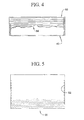
- Figure 4 is a side elevational view illustrating a level indication captured by the digital image capture device of Figure 2 ;
- Figure 5 is a mathematical representation of a level of ice contained within an ice cube storage bin
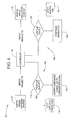
- Figure 6 is a flow chart illustrating an ice level and quality sensing algorithm employed in the present invention.
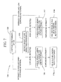
- Figure 7 is a flow chart presenting the details of the quality sensing portion of the ice level and quality sensing system of Figure 6 ;
- Figure 8 is a front view of a refrigerator having a door mounted dispensing system and incorporating an ice level and quality sensing system of the present invention
- Figures 9A-9C illustrate the degradation in quality of ice over time and the formation of ice clumps in the door-mounted ice cube storage bin
- Figure 10 illustrates the use of imaging tools of the present invention to identify and evaluate individual ice cube sizes
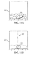
- Figure 11A depicts non-clumped ice within an ice bin
- Figure 11B depicts the non-clumped ice of Figure 10A after image processing
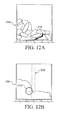
- Figure 12A depicts clumped ice within an ice bin
- Figure 12B depicts the clumped ice of Figure 11A after image processing.
- Refrigerator 2 includes a cabinet 4 having a top wall 6, a bottom wall 7, a rear wall 8, and opposing sidewalls 9 and 10 that collectively define a refrigerator body. Refrigerator 2 is further shown to include a liner 14 that defines a refrigeration compartment, such as a freezer compartment 16. A fresh food compartment 18 is arranged alongside freezer compartment 16 such that refrigerator 2 defines a side-by-side model.
- a cabinet 4 having a top wall 6, a bottom wall 7, a rear wall 8, and opposing sidewalls 9 and 10 that collectively define a refrigerator body.
- Refrigerator 2 is further shown to include a liner 14 that defines a refrigeration compartment, such as a freezer compartment 16.
- a fresh food compartment 18 is arranged alongside freezer compartment 16 such that refrigerator 2 defines a side-by-side model.
- the present invention can be readily incorporated into various refrigerator models, including top mount, bottom mount and French-style door model refrigerators.
- refrigerator 2 includes a freezer compartment door 21 and a fresh food compartment door 22 pivotally mounted to cabinet 4 for selectively providing access to freezer compartment 16 and fresh food compartment 18 respectively.
- each compartment door 21, 22 includes a corresponding handle 24, 25.
- refrigerator 2 is provided with an ice making system 35 including an automatic ice maker 38 positioned above a transparent ice cube storage bin 40.
- ice making system 35 automatically detects a level and quality of ice cubes contained within ice cube storage bin 40.
- ice making system 35 includes a controller 43 which receives input from a digital image capture device 47. Digital images from digital image capture device 47 are passed to a digital image analyzing system 50 which preferably determines both the level and quality of ice cubes within ice cube storage bin 40. Level data is passed to controller 43 to establish ice production cycles for ice maker 38.
- controller 43 will signal ice maker 38 to continue ice production. However, in the event that digital image analyzing system 50 determines that the level of ice cubes in ice cube storage bin 40 is at or above the predetermined level, controller 43 signals ice maker 38 to cease ice production. Also, if digital image analyzing system 50 determines that the quality of ice cubes within ice cube storage bin 40 is below a predetermined level, a signal is presented on a display 54, such as an LCD display, indicating that the ice cubes should be replaced.
- a display 54 such as an LCD display
- digital image capture device 47 takes the form of a digital camera 64.
- Digital camera 64 can take on a variety of forms, such as a charged/coupled device (CCD) camera or complimentary metal oxide semiconductor (CMOS) camera.
- Digital camera 64 is preferably operatively connected to a light source 65 which produces light of one or more wavelengths. That is, light source 65 can bathe ice cube storage bin 40 in white light, colored light or non-visible light depending upon a particular parameter of interest.
- digital camera 64 is operated to capture digital images of ice cubes 66 stored within ice cube storage bin 40.
- ice cubes 66 are contrasted against a reference image 69 for clarity.
- ice bin 40 is arranged between reference image 69 and digital camera 64.
- reference image 69 includes multiple distinct regions 71 which repeat within reference image 69.
- reference image 69 could also be a solid image or simply any desired image chosen to provide contrast for ice cubes 66.
- digital camera 64 is positioned to capture a side view 79 of ice cube storage bin 40, such as shown in Figure 3 , to develop an image profile 84 of ice cubes 66 such as shown in Figure 4 .
- image profile 84 is passed to digital image analyzing system 50. Analyzing system 50 creates a mathematical representation 90 of image profile 84 for evaluation purposes as illustrated in Figure 5 .
- Mathematical representation 90 includes a level indicator or metric 92 which enables analyzing system 50 to determine an actual level of ice cubes 66 in ice cube storage bin 40.
- ice making system 35 includes a first or level analysis portion 100 and a second or quality analysis portion 104.
- level analysis portion 100 determines the particular level of ice cubes 66 within ice cube storage bin 40. More specifically, digital image capture device 47 periodically captures and sends digital images, such as shown in Figure 4 , to controller 43. Controller 43 passes the digital images to digital image analyzing system 50 which produces mathematical representation 90. At this point, analyzing system 50 determines an ice level in ice cube storage bin 40. The result is passed back to controller 43 for review in step 107.
- controller 43 If the level of ice is below a predetermined level, controller 43 signals ice maker 38 to continue making ice in block 109. If, however, the level of ice is at or above the predetermined, desired level, controller 43 signals ice maker 38 to cease ice production at 110.
- ice making system 35 is also capable of determining a quality of the ice within ice cube storage bin 40. As will be detailed more fully below, if controller 43 determines the quality of ice within ice cube storage bin 40 at 115. If the quality of ice is acceptable, display 54 will indicate that the ice is fresh at 115. If the quality is poor, a signal is passed to display 54 indicating that ice cubes 66 should be discarded at 119. After the ice is discarded, ice maker 38 will produce fresh ice which is deposited into ice storage bin 40.
- digital image capture device 47 first captures a photograph or digital image of ice within ice cube storage bin 40 in step 133.
- the digital image is analyzed by digital image analyzing system 50 to determine a level of ice cubes within ice cube storage bin 40 in step 136. If the level of ice cubes is low, digital camera 64 activates light source 65 which bathes ice cubes 66 in light and a new digital image is captured in step 139.
- the new digital image is passed back to digital image analyzing system 50 for analysis.
- Analyzing system 50 includes an edge detection portion 140.
- Edge detection portion 140 employs an edge detection algorithm to determine if edge portions of ice cubes 66 are sharp (indicating that the ice is fresh) or rounded (indicating that the ice cubes are older).
- Digital image analyzing system 50 also evaluates the intensity of ice cubes 66 obtained in the new digital image. If the level of ice cubes 66 is low and the intensity of the ice cubes is uneven, a determination is made that the ice cubes are old and should be discarded. As noted above, a signal is passed to display 54 in step 119a to notify the user that the ice cubes 66 are no longer fresh.
- digital camera 64 activates light source 65 and captures an image of the ice cubes within ice cube storage bin 40 in step 141 using, for example, non-visible light.
- the image captured in step 141 is passed back to digital image analyzing system 50 for analysis. After evaluating edge portions of ice cubes 66, analyzing system 50 evaluates the intensity of the digital image.
- analyzing system 50 determines that the level of ice cubes in ice cube storage bin is high and the image captured in step 141 is uneven, a determination is made that the ice cubes contain voids, are old (e.g., soft with rounded edges) or uneven and should be replaced. This determination is signaled on display 54 in step 119b.
- digital image capture device 47 of the present invention may be utilized in a refrigerator 200 having an automatic ice dispensing system 202 including an ice dispensing bin 204 and a door-mounted dispenser 210 as depicted in Figure 8 .
- Automatic ice dispensing systems such as that employed with the invention, are well known in the art and, therefore, basic details thereof need not be discussed herein. Instead, the manner in which ice making system 35 may be utilized to determine ice shrinking and clumping will now be described in detail.
- digital image capture device 47 periodically captures and sends digital images to controller 43 and controller 43 passes the digital images to digital image analyzing system 50.
- ice cubes 212 in ice dispensing bin 204 may shrink over time and develop clumps of ice such as indicated at 213 in Figure 9C .
- digital image analyzing system 50 will also detect ice shrinkage over time. That is, the digital images of ice cubes located on the outer edges of dispensing bin 204 (i.e., ice cubes in clear view of digital camera 64) are compared to determine differences in ice characteristics from image to image.
- Figure 10 depicts ice size characteristics for a single image taken by digital camera 64.
- digital image analyzing system 50 detects that multiple ice cubes are smaller than a minimum expected cube size, then a signal will be sent to display 54 to indicate stale ice.
- system 50 utilizes multiple image processing methods including edge detection interpolation and region of interest identification (ROI).
- digital image analyzing system 50 monitors ice within ice dispensing bin 204 to detect ice clumping.
- ice dispensing bin 204 includes an auger 218 (see, for example, Figure 12A ) which is positioned in the middle of bin 204 and rotates in order to aide in dispensing ice from bin 204 and preventing ice clumps from forming in bin 204. Therefore, when clumping of ice occurs, the clumps are usually located at the sides and corners of bin 204. For these reasons, monitoring a centroid or center of mass of a volume of ice allows for accurate detection of ice clumps.
- a first image shown in Figure 11A is sent to digital image analyzing system 50 where it is processed to determine a centroid 220 of the volume of ice within bin 204 as depicted in Figure 11B . If system 50 determines that centroid 220 is within a pre-determined boundary indicated at 230, then no clumping event is detected. However, if clumping of ice has occurred, as depicted in Figures 12A and 12B , a centroid 220' of the volume of ice will fall outside of predetermined boundary 230 and system 50 will recognize an ice clumping event. Upon detection of an ice clumping event, a signal is sent to display 54 to alert a user.
- the present invention enables a refrigerator to automatically control ice production to ensure that consumers have an adequate or desired amount of ice.
- the sensing system of the present invention enables the quality of the ice in the ice cube storage bin to be determined.
- consumers are provided the option of discarding ice that may be less than fresh.
- the number and location of cameras can vary in accordance with the present invention. For example, cameras can be located above, behind, alongside or even below the ice cube storage bin to capture digital images.
- the particular color of light employed by the light source can vary in accordance with the present invention to include white light, various colors of light, and, non-visible light in order to reveal different properties of the ice cubes.
- the ice cube storage bin and, for that matter, the ice maker can be door mounted in the freezer compartment or, as indicated above, even provided in a dedicated freezer compartment located within the fresh food compartment of the refrigerator.
- the invention is not limited to dispensing model refrigerators but could be employed in models which make ice that needs to be manually removed from an ice cube storage bin.
Landscapes
- Physics & Mathematics (AREA)
- Electromagnetism (AREA)
- Thermal Sciences (AREA)
- Engineering & Computer Science (AREA)
- Fluid Mechanics (AREA)
- General Physics & Mathematics (AREA)
- Mechanical Engineering (AREA)
- General Engineering & Computer Science (AREA)
- Cold Air Circulating Systems And Constructional Details In Refrigerators (AREA)
- Production, Working, Storing, Or Distribution Of Ice (AREA)
Applications Claiming Priority (1)
| Application Number | Priority Date | Filing Date | Title |
|---|---|---|---|
| US12/550,893 US8156748B2 (en) | 2007-04-27 | 2009-08-31 | Ice quality sensing system employing digital imaging |
Publications (1)
| Publication Number | Publication Date |
|---|---|
| EP2299208A2 true EP2299208A2 (de) | 2011-03-23 |
Family
ID=43303275
Family Applications (1)
| Application Number | Title | Priority Date | Filing Date |
|---|---|---|---|
| EP10173779A Withdrawn EP2299208A2 (de) | 2009-08-31 | 2010-08-24 | Eisqualitätsmesssystem mit digitaler Bildgebung |
Country Status (2)
| Country | Link |
|---|---|
| US (1) | US8156748B2 (de) |
| EP (1) | EP2299208A2 (de) |
Cited By (1)
| Publication number | Priority date | Publication date | Assignee | Title |
|---|---|---|---|---|
| WO2023153654A1 (ko) * | 2022-02-10 | 2023-08-17 | 삼성전자주식회사 | 냉장고 및 냉장고의 제어방법 |
Families Citing this family (20)
| Publication number | Priority date | Publication date | Assignee | Title |
|---|---|---|---|---|
| JP2008011266A (ja) * | 2006-06-29 | 2008-01-17 | Ricoh Co Ltd | 複合画像形成方法及び複合画像形成装置 |
| US20080072610A1 (en) * | 2006-09-26 | 2008-03-27 | General Electric Company | Apparatus and method for controlling operation of an icemaker |
| KR101456572B1 (ko) * | 2008-05-27 | 2014-10-31 | 엘지전자 주식회사 | 냉장고 제빙기의 만빙 감지 장치의 센서 히터 제어 방법 |
| KR101535481B1 (ko) * | 2008-04-15 | 2015-07-09 | 엘지전자 주식회사 | 냉장고 제빙기의 만빙 감지 장치 |
| KR101456571B1 (ko) * | 2008-05-01 | 2014-10-31 | 엘지전자 주식회사 | 냉장고 제빙기의 만빙 감지 장치 및 그 만빙 감지 방법 |
| KR101474439B1 (ko) * | 2008-05-27 | 2014-12-19 | 엘지전자 주식회사 | 냉장고 제빙기의 만빙 감지 장치의 센서 히터 제어 방법 |
| US20100139299A1 (en) * | 2008-04-15 | 2010-06-10 | Dong-Hoon Lee | Refrigerator and full ice level sensing apparatus thereof |
| KR101535484B1 (ko) * | 2008-04-15 | 2015-07-09 | 엘지전자 주식회사 | 냉장고 제빙기의 만빙 감지 장치 |
| KR101535482B1 (ko) * | 2008-04-15 | 2015-07-09 | 엘지전자 주식회사 | 냉장고 제빙기의 만빙 감지 장치 |
| KR20110044014A (ko) * | 2009-10-22 | 2011-04-28 | 엘지이노텍 주식회사 | 냉장고의 성에 제거 시스템 및 그 방법 |
| KR101201101B1 (ko) * | 2010-03-26 | 2012-11-13 | 웅진코웨이주식회사 | 냉수탱크 |
| DE102010034176A1 (de) * | 2010-08-12 | 2012-02-16 | Würth Elektronik Ics Gmbh & Co. Kg | Behälter mit Erfassungsvorrichtung |
| CA2771634A1 (en) * | 2011-03-10 | 2012-09-10 | Spinnaker Process Instruments | Networked freezer stocking management |
| DE102012201089A1 (de) * | 2012-01-25 | 2013-07-25 | BSH Bosch und Siemens Hausgeräte GmbH | Kältegerät mit einem kältefach |
| JP6313014B2 (ja) * | 2013-08-27 | 2018-04-18 | 東芝ライフスタイル株式会社 | カメラシステム、冷蔵庫 |
| US9243833B2 (en) * | 2013-11-05 | 2016-01-26 | General Electric Company | Ice making system for a refrigerator appliance and a method for determining an ice level within an ice bucket |
| US10731908B2 (en) | 2017-04-26 | 2020-08-04 | Electrolux Home Products, Inc. | Refrigeration appliance with cold air supply for ice maker and ice level sensor |
| KR102551358B1 (ko) * | 2018-09-21 | 2023-07-04 | 삼성전자주식회사 | 냉장고 내 객체의 상태와 관련된 정보를 제공하는 방법 및 시스템 |
| CN113625606B (zh) * | 2021-08-11 | 2022-11-15 | 上海秉越电子仪器有限公司 | 一种医用无尖刺冰泥制作控制系统 |
| US11747071B2 (en) | 2021-10-07 | 2023-09-05 | Haier Us Appliance Solutions, Inc. | Systems and methods for detecting and monitoring ice formation within an ice maker |
Family Cites Families (17)
| Publication number | Priority date | Publication date | Assignee | Title |
|---|---|---|---|---|
| US4822996A (en) | 1986-04-03 | 1989-04-18 | King-Seeley Thermos Company | Ice bin level sensor with time delay |
| US4938030A (en) | 1986-12-04 | 1990-07-03 | Schneider Metal Manufacturing Co. | Ice cube maker with new freeze and harvest control |
| JP3332483B2 (ja) | 1993-06-15 | 2002-10-07 | 三洋電機株式会社 | 氷供給装置 |
| US5901561A (en) | 1997-06-12 | 1999-05-11 | Scotsman Group, Inc. | Fault restart method |
| US6414301B1 (en) | 1998-05-14 | 2002-07-02 | Hoshizaki America, Inc. | Photoelectric ice bin control system |
| US6314745B1 (en) | 1998-12-28 | 2001-11-13 | Whirlpool Corporation | Refrigerator having an ice maker and a control system therefor |
| US6082130A (en) | 1998-12-28 | 2000-07-04 | Whirlpool Corporation | Ice delivery system for a refrigerator |
| US6050097A (en) | 1998-12-28 | 2000-04-18 | Whirlpool Corporation | Ice making and storage system for a refrigerator |
| US6351958B1 (en) | 2000-01-12 | 2002-03-05 | Whirlpool Corporation | Optic level sensing system for use in a refrigerator |
| US6561691B1 (en) | 2000-04-07 | 2003-05-13 | Tmo Enterprises Limited | Method and apparatus for the distribution of ice |
| SE522000C2 (sv) * | 2000-08-18 | 2004-01-07 | Rutger Roseen | Förfarande och anordning för att hålla reda på lagringstiden för i ett utrymme förvarade varor |
| JP2002156181A (ja) * | 2000-11-16 | 2002-05-31 | Yozan Inc | 冷蔵庫 |
| JP2002295959A (ja) | 2001-03-28 | 2002-10-09 | Seiko Epson Corp | 撮影装置付き冷蔵庫 |
| US6511694B2 (en) | 2001-04-06 | 2003-01-28 | The Pillsbury Company | Stable soft frozen desserts |
| AU5069202A (en) * | 2002-01-17 | 2003-07-24 | Lg Electronics Inc. | Apparatus and method for controlling cool air in refrigerator |
| US6581392B1 (en) | 2002-02-01 | 2003-06-24 | Scotsman Ice Systems | Ice machine and method for control thereof |
| US20060096303A1 (en) * | 2004-11-10 | 2006-05-11 | Kavounas Gregory T | Home refrigerator systems imaging their interior and methods |
-
2009
- 2009-08-31 US US12/550,893 patent/US8156748B2/en not_active Expired - Fee Related
-
2010
- 2010-08-24 EP EP10173779A patent/EP2299208A2/de not_active Withdrawn
Non-Patent Citations (1)
| Title |
|---|
| None |
Cited By (1)
| Publication number | Priority date | Publication date | Assignee | Title |
|---|---|---|---|---|
| WO2023153654A1 (ko) * | 2022-02-10 | 2023-08-17 | 삼성전자주식회사 | 냉장고 및 냉장고의 제어방법 |
Also Published As
| Publication number | Publication date |
|---|---|
| US20100046793A1 (en) | 2010-02-25 |
| US8156748B2 (en) | 2012-04-17 |
Similar Documents
| Publication | Publication Date | Title |
|---|---|---|
| US8156748B2 (en) | Ice quality sensing system employing digital imaging | |
| US9989295B2 (en) | Ice imaging system | |
| US8713949B2 (en) | Ice level and quality sensing system employing digital imaging | |
| US11235965B2 (en) | Hands free, controlled autofill for a dispenser | |
| US8322384B2 (en) | Select-fill dispensing system | |
| KR101456571B1 (ko) | 냉장고 제빙기의 만빙 감지 장치 및 그 만빙 감지 방법 | |
| US12062015B2 (en) | Refrigerator with contents monitoring system | |
| US8578730B2 (en) | Refrigerator ice and liquid dispenser incorporating imaging system | |
| KR101847703B1 (ko) | 물 자동급수장치 | |
| KR101830496B1 (ko) | 물 자동급수장치 | |
| EP4414634A1 (de) | System und verfahren zur erkennung und überwachung der eisbildung in einem eiserzeuger | |
| US20250164172A1 (en) | Refrigerator appliance and ice clumping prevention |
Legal Events
| Date | Code | Title | Description |
|---|---|---|---|
| PUAI | Public reference made under article 153(3) epc to a published international application that has entered the european phase |
Free format text: ORIGINAL CODE: 0009012 |
|
| AK | Designated contracting states |
Kind code of ref document: A2 Designated state(s): AL AT BE BG CH CY CZ DE DK EE ES FI FR GB GR HR HU IE IS IT LI LT LU LV MC MK MT NL NO PL PT RO SE SI SK SM TR |
|
| AX | Request for extension of the european patent |
Extension state: BA ME RS |
|
| STAA | Information on the status of an ep patent application or granted ep patent |
Free format text: STATUS: THE APPLICATION HAS BEEN WITHDRAWN |
|
| 18W | Application withdrawn |
Effective date: 20170518 |