EP2299032A2 - Druck anwendender, teleskopischer Abstandshalter - Google Patents
Druck anwendender, teleskopischer Abstandshalter Download PDFInfo
- Publication number
- EP2299032A2 EP2299032A2 EP10008459A EP10008459A EP2299032A2 EP 2299032 A2 EP2299032 A2 EP 2299032A2 EP 10008459 A EP10008459 A EP 10008459A EP 10008459 A EP10008459 A EP 10008459A EP 2299032 A2 EP2299032 A2 EP 2299032A2
- Authority
- EP
- European Patent Office
- Prior art keywords
- spacer
- pressure
- sheet metal
- metal rings
- outer tube
- Prior art date
- Legal status (The legal status is an assumption and is not a legal conclusion. Google has not performed a legal analysis and makes no representation as to the accuracy of the status listed.)
- Granted
Links
Images


Classifications
-
- E—FIXED CONSTRUCTIONS
- E04—BUILDING
- E04G—SCAFFOLDING; FORMS; SHUTTERING; BUILDING IMPLEMENTS OR AIDS, OR THEIR USE; HANDLING BUILDING MATERIALS ON THE SITE; REPAIRING, BREAKING-UP OR OTHER WORK ON EXISTING BUILDINGS
- E04G21/00—Preparing, conveying, or working-up building materials or building elements in situ; Other devices or measures for constructional work
- E04G21/24—Safety or protective measures preventing damage to building parts or finishing work during construction
- E04G21/26—Strutting means for wall parts; Supports or the like, e.g. for holding in position prefabricated walls
-
- B—PERFORMING OPERATIONS; TRANSPORTING
- B60—VEHICLES IN GENERAL
- B60P—VEHICLES ADAPTED FOR LOAD TRANSPORTATION OR TO TRANSPORT, TO CARRY, OR TO COMPRISE SPECIAL LOADS OR OBJECTS
- B60P7/00—Securing or covering of load on vehicles
- B60P7/06—Securing of load
- B60P7/135—Securing or supporting by load bracing means
- B60P7/15—Securing or supporting by load bracing means the load bracing means comprising a movable bar
-
- B—PERFORMING OPERATIONS; TRANSPORTING
- B61—RAILWAYS
- B61D—BODY DETAILS OR KINDS OF RAILWAY VEHICLES
- B61D45/00—Means or devices for securing or supporting the cargo, including protection against shocks
-
- E—FIXED CONSTRUCTIONS
- E04—BUILDING
- E04G—SCAFFOLDING; FORMS; SHUTTERING; BUILDING IMPLEMENTS OR AIDS, OR THEIR USE; HANDLING BUILDING MATERIALS ON THE SITE; REPAIRING, BREAKING-UP OR OTHER WORK ON EXISTING BUILDINGS
- E04G25/00—Shores or struts; Chocks
- E04G25/04—Shores or struts; Chocks telescopic
- E04G25/08—Shores or struts; Chocks telescopic with parts held relatively to each other by friction or gripping
-
- F—MECHANICAL ENGINEERING; LIGHTING; HEATING; WEAPONS; BLASTING
- F16—ENGINEERING ELEMENTS AND UNITS; GENERAL MEASURES FOR PRODUCING AND MAINTAINING EFFECTIVE FUNCTIONING OF MACHINES OR INSTALLATIONS; THERMAL INSULATION IN GENERAL
- F16B—DEVICES FOR FASTENING OR SECURING CONSTRUCTIONAL ELEMENTS OR MACHINE PARTS TOGETHER, e.g. NAILS, BOLTS, CIRCLIPS, CLAMPS, CLIPS OR WEDGES; JOINTS OR JOINTING
- F16B7/00—Connections of rods or tubes, e.g. of non-circular section, mutually, including resilient connections
- F16B7/10—Telescoping systems
- F16B7/14—Telescoping systems locking in intermediate non-discrete positions
-
- F—MECHANICAL ENGINEERING; LIGHTING; HEATING; WEAPONS; BLASTING
- F16—ENGINEERING ELEMENTS AND UNITS; GENERAL MEASURES FOR PRODUCING AND MAINTAINING EFFECTIVE FUNCTIONING OF MACHINES OR INSTALLATIONS; THERMAL INSULATION IN GENERAL
- F16B—DEVICES FOR FASTENING OR SECURING CONSTRUCTIONAL ELEMENTS OR MACHINE PARTS TOGETHER, e.g. NAILS, BOLTS, CIRCLIPS, CLAMPS, CLIPS OR WEDGES; JOINTS OR JOINTING
- F16B2/00—Friction-grip releasable fastenings
- F16B2/20—Clips, i.e. with gripping action effected solely by the inherent resistance to deformation of the material of the fastening
- F16B2/22—Clips, i.e. with gripping action effected solely by the inherent resistance to deformation of the material of the fastening of resilient material, e.g. rubbery material
- F16B2/24—Clips, i.e. with gripping action effected solely by the inherent resistance to deformation of the material of the fastening of resilient material, e.g. rubbery material of metal
- F16B2/241—Clips, i.e. with gripping action effected solely by the inherent resistance to deformation of the material of the fastening of resilient material, e.g. rubbery material of metal of sheet metal
- F16B2/245—Clips, i.e. with gripping action effected solely by the inherent resistance to deformation of the material of the fastening of resilient material, e.g. rubbery material of metal of sheet metal external, i.e. with contracting action
- F16B2/246—Clips, i.e. with gripping action effected solely by the inherent resistance to deformation of the material of the fastening of resilient material, e.g. rubbery material of metal of sheet metal external, i.e. with contracting action the clip being released by tilting the clip or a part thereof to a position in which the axis of the openings surrounding the gripped elements is parallel to, or coincides with, the axis of the gripped elements
Definitions
- the present invention relates to a pressure-applying telescopic spacer, which constitutes a manually operated tool for the evident purpose of establishing a distance and maintaining it under stress or a load, either by supporting the ends in parallel planes, or in perpendicular planes, or in planes forming an angle with one another, linear, or others that may exist.
- the object of the invention is to obtain a telescopic spacer that can work both by pressure and by pulling on the elements or portions to be spaced, providing a wide range of distances for a single level of the spacer, being versatile, structurally simple, lightweight, with instinctive and easy handling, being able to be handled using only one hand.
- Types of telescopic spacers mainly used in construction and used as props generally for supporting the formworks used in building floors, are known today.
- telescopic props are expandable and are made in multiple forms, having the common denominator that they all have unpractical locking means, in addition to being not altogether effective and difficult to being hard to handle and operate.
- the pressure-applying telescopic spacer that is proposed, being formed from two tubes telescopically coupled to one another, has novelty features that will be explained through the present description, which lead to advantages and new characteristics that will also be described.
- the spacer of the invention has as its main novelty features blocking means for blocking the axial movement between the tubes, these blocking means formed by sheet metal rings placed on top of one another forming a block, through which there passes with clearance the inner tube, said sheet metal rings being assembled on a part anchored on the outer tube, supported thereon through a portion or area of said rings, whereas in another opposite area or portion of said sheet metal rings there is supported and there applies pressure a spring which is intended for pivoting said rings towards a wedged (crossed) position in which the aforementioned sheet metal rings are driven into the inner tube, establishing the blocking of the latter so as to prevent its axial movement in the retracting direction with respect to the outer tube.
- a manual operation on the spring pressing against the sheet metal rings will allow recovering the normal position thereof, i.e., releasing the crossed position due to the wedging thereof, and thus achieve the unblocking to allow the axial movement of the inner tube with respect to the outer tube and establish the measurement of the spacer between the two portions or surfaces between which it must be assembled.
- the part for assembling the sheet metal rings used in the blocking of the two tubes of the spacer is preferably formed by a sort of sleeve assembled on the outer tube, such that one of the ends of that sleeve includes anchoring and immobilizing means for being anchored and immobilized on the outer tube, whereas the other end of such sleeve has a head-like expansion in which the sheet metal rings and the spring itself for pushing the former are arranged.
- the operation for the unblocking and corresponding sliding of the inner tube with respect to the outer tube can be carried out with both hands, one of them for acting on the spring and the other one for sliding the tube, although it can also be carried out with only one hand in the vertical position of the spacer, such that in said position, if the spring is acted upon and the unblocking is established, the inner tube can slide by itself by gravity due to its own weight.
- the spacer can only vary its measurement in the lengthening or extensibility direction, if the inner tube is pulled until overcoming the force of the spring, thus adopting a new dimension, thus coming closer to the required measurement or dimension.
- the inner tube will be completed with a stop limiting the sliding in the extensibility direction, to prevent it from being uncoupled from the outer tube.
- the spacer as a whole is complemented with respective supports provided at the free end of its tubes, the supports being formed by respective plates pivotably assembled on the ends of the tubes, such plates being able to adopt any angle, i.e., any inclination, furthermore having holes for the passage of screws or elements for fixing such plates on the bodies or surfaces to be spaced, i.e., between which the spacer is assembled.
- the support plate corresponding to the end considered as the lower end, or in other words of the outer tube, is connected with a sleeve through a rod and a spring, determining an approximation mechanism which gives way when it is operated to reduce the dimension or length of the spacer, which mechanism is practical when a slight pressure is required for the spacer to be fitted or to be maintained alone while performing other complementary adjustment work.
- the corresponding plate In relation to the upper support, i.e., the one corresponding to the free end of the inner tube, the corresponding plate is connected with the tube through a threaded rod with a nut established inside the end of the tube, forming a pressure-applying mechanism, such that in the rotation of the assembly of the spacer an increase of decrease of the final distance of the spacer itself or its pressure on the surfaces between which it is applied, depending on the rotation direction carried out, will be established.
- Said pressure-applying mechanism allows establishing a final approximation to the determined distance, or supplying a desired pressure thereon, in the event that the assembly of the spacer continues to be rotated once the contact has been reached.
- the pivoting assembly of the plates corresponding to the considered supports of the spacer allows such plates to be able to take on different inclinations or angles, which confers to the spacer a greater plurality since it is possible to space not only vertical levels but also inclined and even horizontal levels, provided that such plates are fixed, through their holes, to the surfaces between which the spacer is applied, which fixing can be performed on any type of surface.
- the plates will be complemented with elastic protectors to prevent sliding and marks of the surfaces to be spaced between which it is supported.
- the described spacer in addition to the features and characteristics thereof which have been mentioned, is resistance to the most severe and delicate conditions of use, without therefore having to limit the function of regulation or pressure between the distance to be delimited.
- Another advantage of the spacer is its easy, simple and quick release and recovery system, allowing its use with only one hand, in addition to taking advantage of the contradictory stresses of the components and intervening parts to be self-fixed more intensely as the stressing to which it is exposed at both ends increases.
- Another advantage is that it allows, by means of a minimal pressure, reaching its desired positioning, remaining stable in such position, prior to the position to be adopted, while it is decided whether the final arrangement of the actual spacer is that one or another one.
- the part assembled on the outer tube in which the sheet metal discs for blocking and the spring for pushing the former are in turn assembled, forms what can be considered as a manually operated handle for acting on said blocking means, i.e., on the sheet metal discs, as well as for increasing or decreasing the length of the spacer, for increasing the pressure on the surface of support by means of the rotation of the assembly, etc.
- such part which as has been stated above has a general sleeve shape, determining a volume including and harmonizing the assembly of components which makes the spacer operate.
- the spacer is reusable, with the possibility of exchanging the support plates for their use in various applications and allowing the use thereof to exert pressure or to exert pulling, in the latter case by substituting the support plates with simple hooks.
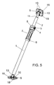
- the telescopic spacer of the invention is formed from two tubes (1 and 2) telescopically coupled to one another, the inner tube (2) being provided with a stop (3) limiting the movement in the extensibility direction thereof to prevent it from being unlinked from the outer tube (1).
- the blocking between tubes to prevent the extensibility and/or retraction thereof is achieved by means of sheet metal rings (4) placed on top of one another forming a joint ring through which there passes the inner tube (2) itself, which sheet metal rings (4) in the position of perpendicularity to the inner tube (2) itself allow the free movement thereof in the axial direction.
- those sheet metal rings (4) are driven by a spring (5) pressing on one of the end portions, intended for the wedging and driving of those sheet metal rings (4) on the inner tube (2) itself, since the other portion of such sheet metal rings (4) is supported on a part (6) assembled on the outer tube, which part (6) forms part of a sort of sleeve (7) provided at one of its ends with anchoring springs (8) for fixing that part (6) on the outer tube (1), since the other end, corresponding to reference number (6), forms an expansion or head in which the sheet metal rings (4) and the spring (5) itself are precisely housed, as can be clearly seen in Figures 1 and 2 .
- part (6) or assembly formed by the latter with the portion of the sleeve (7) form a sort of manually operated handle for the spacer.
- the positioning between the two surfaces to be spaced is performed by means of respective support plates (9) provided at the free ends of the tubes (1 and 2), such that the support plate (9) provided at the upper end, i.e., at the free end of the inner tube (2), is pivotably assembled through a pin or similar element with respect to a threaded rod (11), which is in turn screwed onto a threaded sleeve (12) established at the end of the inner tube (2), as can be seen in the detail of Figure 3 .
- the lower support plate (9), corresponding to the end of the outer tube (1), is in turn also pivotably assembled through another shaft or pin (10), like the one mentioned above, and which pivoting is performed with respect to a rod (13) projecting from the plate (9) itself, which rod has a limit flange (14) against the bottom (15) of a slot established in a sleeve (16) provided at the lower end of the outer tube, there being a spring (17) between the aforementioned limit flange (14) and the bottom of the sleeve (16).
- the support plates (9) can be complemented with a protective and non-slip surface (18) to prevent not only the sliding but also friction on the surfaces in which it is applied, which plates (9) in turn have through holes (19) for screws for fixing them to the surface in which they are applied.
- the mentioned plates (9) can be exchanged and substituted with hooks (20), as depicted in Figure 2 , and the spacer can be used as a pulling element instead of a pressure-applying element according to what has been mentioned above, with the particularity that in this case, i.e., in the embodiment of Figure 2 or when the spacer includes the hooks (20), the arrangement of the sheet metal discs (4) and the spring (5) is then reverse to the one shown in Figure 1 , and the same occurs with the limit flange (14) which is in the reverse situation, as can be clearly seen in this Figure 2 .
Landscapes
- Engineering & Computer Science (AREA)
- Architecture (AREA)
- Mechanical Engineering (AREA)
- Civil Engineering (AREA)
- Structural Engineering (AREA)
- General Engineering & Computer Science (AREA)
- Transportation (AREA)
- Forms Removed On Construction Sites Or Auxiliary Members Thereof (AREA)
- Clamps And Clips (AREA)
- Tents Or Canopies (AREA)
- Measuring Fluid Pressure (AREA)
Applications Claiming Priority (1)
| Application Number | Priority Date | Filing Date | Title |
|---|---|---|---|
| ES200901925A ES2380466B5 (es) | 2009-09-22 | 2009-09-22 | Distanciador telescopico de presion |
Publications (3)
| Publication Number | Publication Date |
|---|---|
| EP2299032A2 true EP2299032A2 (de) | 2011-03-23 |
| EP2299032A3 EP2299032A3 (de) | 2013-05-15 |
| EP2299032B1 EP2299032B1 (de) | 2017-11-22 |
Family
ID=43382452
Family Applications (1)
| Application Number | Title | Priority Date | Filing Date |
|---|---|---|---|
| EP10008459.9A Not-in-force EP2299032B1 (de) | 2009-09-22 | 2010-08-13 | Druck anwendender, teleskopischer Abstandshalter |
Country Status (3)
| Country | Link |
|---|---|
| US (1) | US8496217B2 (de) |
| EP (1) | EP2299032B1 (de) |
| ES (1) | ES2380466B5 (de) |
Cited By (4)
| Publication number | Priority date | Publication date | Assignee | Title |
|---|---|---|---|---|
| CN111395787A (zh) * | 2020-04-25 | 2020-07-10 | 田朝明 | 一种装配式建筑墙板安装辅助装置 |
| CN111962891A (zh) * | 2020-08-25 | 2020-11-20 | 福建建工亚鹰建筑科技发展有限公司 | 一种装配式建筑搭建用辅助固定机构 |
| CN112780105A (zh) * | 2021-02-04 | 2021-05-11 | 浙江本和建筑科技发展有限公司 | 一种易拆装建筑临边防护 |
| WO2021180756A1 (en) * | 2020-03-11 | 2021-09-16 | Nordiska Balco Ab | Telescopic pillar system and the use of such pillar system |
Families Citing this family (27)
| Publication number | Priority date | Publication date | Assignee | Title |
|---|---|---|---|---|
| WO2014018804A1 (en) * | 2012-07-25 | 2014-01-30 | Tarpy Paul | Duct stiffening device |
| US20160200557A1 (en) * | 2013-08-09 | 2016-07-14 | Je Hwan CHO | Vehicle lifter |
| US10576936B2 (en) * | 2015-12-07 | 2020-03-03 | James M. Markarian | Holder for motor vehicle wiper arms |
| USD793648S1 (en) * | 2016-01-08 | 2017-08-01 | Ningbo Zhongtian Union Mechanical & Electrical Manufacturing Co., Ltd. | Lifting cylinder |
| USD789015S1 (en) * | 2016-07-15 | 2017-06-06 | Ningbo Yinzhou Zhongtian Hydraulic Co., Ltd. | Lifting cylinder with balanced valve |
| KR101864849B1 (ko) * | 2017-11-09 | 2018-06-05 | 주식회사 신우기술 | 교량 재하 시험 장치 |
| KR101860927B1 (ko) * | 2017-11-09 | 2018-05-24 | 주식회사 흥찬엔지니어링 | 교량 재하 시험 장치 |
| WO2019162486A1 (en) * | 2018-02-26 | 2019-08-29 | Safetyrespect Ab | Support post |
| KR101932237B1 (ko) | 2018-05-10 | 2018-12-24 | 주식회사 흥찬엔지니어링 | 굴곡진 면인 지지부에서 사용 가능한 교량 재하 시험 장치 |
| KR101942462B1 (ko) | 2018-05-10 | 2019-01-28 | 주식회사 신우기술 | 지지부에 밀착되어 체결될 수 있는 교량 재하 시험 장치 |
| KR101932239B1 (ko) | 2018-05-10 | 2018-12-24 | 주식회사 흥찬엔지니어링 | 마찰을 최소화하며 굴곡진 면인 지지부에서 사용 가능한 교량 재하 시험 장치 |
| KR101932240B1 (ko) | 2018-05-10 | 2018-12-24 | 주식회사 흥찬엔지니어링 | 시험 대상 교량에 밀착될 수 있는 교량 재하 시험 장치 |
| KR101942461B1 (ko) | 2018-05-10 | 2019-01-28 | 주식회사 신우기술 | 시험 대상 교량에 밀착될 수 있는 교량 재하 시험 장치 |
| KR101942460B1 (ko) | 2018-05-10 | 2019-01-28 | 주식회사 신우기술 | 마찰이 최소화된 교량 재하 시험 장치 |
| KR101932238B1 (ko) | 2018-05-10 | 2018-12-24 | 주식회사 흥찬엔지니어링 | 마찰을 최소화한 교량 재하 시험 장치 |
| KR101942463B1 (ko) | 2018-05-10 | 2019-01-28 | 주식회사 신우기술 | 굴곡진 면인 지지부에서 사용 가능한 교량 재하 시험 장치 |
| US11097797B1 (en) * | 2019-03-27 | 2021-08-24 | Ryan Zeller | Wheel securing apparatus and method of use |
| US11208819B2 (en) * | 2019-07-12 | 2021-12-28 | Charles J. Mackarvich | Compression post with visual indication system |
| US11098493B2 (en) * | 2019-07-12 | 2021-08-24 | Charles J. Mackarvich | Compression post with retainer clip |
| US11927026B2 (en) * | 2020-03-16 | 2024-03-12 | Brandon W Baker | Pole stabilization assembly |
| CA3220514A1 (en) * | 2021-05-26 | 2022-12-01 | Robert GOLDSPINK | Improved prop assemblies |
| CN113404056A (zh) * | 2021-07-13 | 2021-09-17 | 上海茂裕建设工程有限公司 | 一种深基坑内取代换撑的钢管托换装置 |
| CN113530002B (zh) * | 2021-08-13 | 2022-07-08 | 山东天元建设机械有限公司 | 一种金属阻尼器安装装置及其施工方法 |
| CN114086774B (zh) * | 2021-12-17 | 2023-07-04 | 中国二十冶集团有限公司 | 预制墙板支撑方法 |
| CN114673348A (zh) * | 2022-03-03 | 2022-06-28 | 中国二冶集团有限公司 | 一种模板支撑器 |
| CN114718948B (zh) * | 2022-04-29 | 2023-09-01 | 四川化工职业技术学院 | 一种多功能机械工具扩展装置 |
| US12398742B1 (en) * | 2025-01-17 | 2025-08-26 | Shenzhen Zhihui Youpin Technology Co., LTD | Storage pole facilitating telescopic control adjustment |
Citations (5)
| Publication number | Priority date | Publication date | Assignee | Title |
|---|---|---|---|---|
| ES474270A3 (es) | 1978-10-17 | 1979-04-16 | Sirte S A | Puntal telescopico para encofrados de forjados. |
| ES245475U (es) | 1979-09-07 | 1980-01-01 | Mengibar Almagro Manuel | Puntal telescopico |
| ES1004562U (es) | 1988-02-01 | 1988-10-01 | Ajuria Larrea Antonio | Dispositivo de puntal telescopico. |
| ES1006160U (es) | 1987-08-27 | 1988-12-16 | Iglesias Cubillas Jose | Puntal telescopico para la construccion de obras y edificaciones. |
| ES1060333U (es) | 2005-05-17 | 2005-08-16 | David Pascual Ezama | Puntal telescopico. |
Family Cites Families (17)
| Publication number | Priority date | Publication date | Assignee | Title |
|---|---|---|---|---|
| BE531717A (de) * | ||||
| US2051969A (en) * | 1935-01-16 | 1936-08-25 | Louis W Shastock | Automatic tube adjuster for telescoping tubes |
| US2483395A (en) * | 1945-05-14 | 1949-10-04 | Chisholm Ryder Co Inc | Telescoping structure |
| US2504291A (en) * | 1945-07-18 | 1950-04-18 | Brainard Steel Company | Telescopic and adjustable building support |
| GB722819A (en) * | 1951-06-08 | 1955-02-02 | Jean Rodolphe Meili | Improvements in or relating to devices for locking telescopically-arranged tubes andprops comprising such tubes |
| US3210047A (en) * | 1963-06-17 | 1965-10-05 | Jackson George Wilbert | Shoring jack |
| JPS5513757U (de) * | 1978-07-13 | 1980-01-29 | ||
| FR2450324A1 (fr) * | 1979-02-27 | 1980-09-26 | Cinotto Simon | Dispositif de stabilisation pour panneaux verticaux |
| US5238213A (en) * | 1992-04-01 | 1993-08-24 | Lisle Corporation | Extendable support |
| JPH0649659U (ja) * | 1992-12-16 | 1994-07-08 | 株式会社長谷工コーポレーション | 伸縮式支持具 |
| WO1997046776A1 (en) * | 1996-06-07 | 1997-12-11 | Haworth, Inc. | Portable multiple-purpose floor-ceiling column for office |
| US5826847A (en) * | 1997-06-30 | 1998-10-27 | Warner; Stanley H. | Telescoping pole with quick length adjustment |
| US5988963A (en) * | 1998-10-26 | 1999-11-23 | Shiau; Hing-Horng | Cargo positioning frame |
| US6179514B1 (en) * | 1999-05-28 | 2001-01-30 | Kun-Chia Cheng | Telescopic tube joint |
| TW553332U (en) * | 2000-03-28 | 2003-09-11 | Chiung-Mei Huang | Improved alignment apparatus for retractable supporting shaft |
| CA2515750C (en) * | 2005-08-10 | 2014-06-03 | Jonathan Jonny Melic | Locking and lifting mechanism for safety fence support post |
| AU2007250511A1 (en) * | 2006-05-11 | 2007-11-22 | Cps Investment Holdings Pty Ltd | Building brace |
-
2009
- 2009-09-22 ES ES200901925A patent/ES2380466B5/es active Active
-
2010
- 2010-08-13 EP EP10008459.9A patent/EP2299032B1/de not_active Not-in-force
- 2010-09-17 US US12/885,275 patent/US8496217B2/en not_active Expired - Fee Related
Patent Citations (5)
| Publication number | Priority date | Publication date | Assignee | Title |
|---|---|---|---|---|
| ES474270A3 (es) | 1978-10-17 | 1979-04-16 | Sirte S A | Puntal telescopico para encofrados de forjados. |
| ES245475U (es) | 1979-09-07 | 1980-01-01 | Mengibar Almagro Manuel | Puntal telescopico |
| ES1006160U (es) | 1987-08-27 | 1988-12-16 | Iglesias Cubillas Jose | Puntal telescopico para la construccion de obras y edificaciones. |
| ES1004562U (es) | 1988-02-01 | 1988-10-01 | Ajuria Larrea Antonio | Dispositivo de puntal telescopico. |
| ES1060333U (es) | 2005-05-17 | 2005-08-16 | David Pascual Ezama | Puntal telescopico. |
Cited By (4)
| Publication number | Priority date | Publication date | Assignee | Title |
|---|---|---|---|---|
| WO2021180756A1 (en) * | 2020-03-11 | 2021-09-16 | Nordiska Balco Ab | Telescopic pillar system and the use of such pillar system |
| CN111395787A (zh) * | 2020-04-25 | 2020-07-10 | 田朝明 | 一种装配式建筑墙板安装辅助装置 |
| CN111962891A (zh) * | 2020-08-25 | 2020-11-20 | 福建建工亚鹰建筑科技发展有限公司 | 一种装配式建筑搭建用辅助固定机构 |
| CN112780105A (zh) * | 2021-02-04 | 2021-05-11 | 浙江本和建筑科技发展有限公司 | 一种易拆装建筑临边防护 |
Also Published As
| Publication number | Publication date |
|---|---|
| EP2299032B1 (de) | 2017-11-22 |
| EP2299032A3 (de) | 2013-05-15 |
| ES2380466B5 (es) | 2020-03-24 |
| ES2380466B1 (es) | 2013-03-22 |
| US20110068568A1 (en) | 2011-03-24 |
| ES2380466A1 (es) | 2012-05-11 |
| US8496217B2 (en) | 2013-07-30 |
Similar Documents
| Publication | Publication Date | Title |
|---|---|---|
| EP2299032A2 (de) | Druck anwendender, teleskopischer Abstandshalter | |
| KR100970820B1 (ko) | 사진기용 삼각대 | |
| EP2984256B1 (de) | Verbesserungen an einem ladegutentriegelungsmittel für teleskopische stützen | |
| US10125608B2 (en) | Temporary support and raising device | |
| US9161664B2 (en) | Shower rod with spring adjustment | |
| US10352344B2 (en) | Telescoping assembly | |
| EP2318618B1 (de) | Baustütze | |
| KR102812825B1 (ko) | 텔레스코픽 에지 보호 포스트 | |
| US9066637B2 (en) | Shower rod with macro and micro adjustment | |
| US20120068036A1 (en) | Pressure-applying telescopic spacer | |
| WO2013173713A1 (en) | Unitary, strike, drop-in anchor for concrete and the like | |
| CA2236062A1 (en) | A pit prop | |
| JP6220471B1 (ja) | 転倒防止支柱 | |
| EP2455564A1 (de) | Druckaufbringendes teleskopisches Distanzstück | |
| US3706441A (en) | Jacking devices | |
| CN222534049U (zh) | 一种可快速调节长度的装置 | |
| RU128911U1 (ru) | Опора трубопровода | |
| JP2007205081A (ja) | 支保工用パイプサポートの荷重解放装置 | |
| US2465378A (en) | Clamp | |
| CN214302822U (zh) | 一种脚手架用固定装置 | |
| JP3209688U (ja) | 手摺 | |
| NO311554B1 (no) | Teleskopisk stang | |
| HRP20090202A2 (hr) | Građevinska dvostrana i jednostrana stezna stopa | |
| CN114016734A (zh) | 建筑模板浇筑用固定结构及其使用方法 | |
| CS207229B1 (cs) | Zdvihací stojany k odvíjení kabelů z kabelových bubnů |
Legal Events
| Date | Code | Title | Description |
|---|---|---|---|
| PUAI | Public reference made under article 153(3) epc to a published international application that has entered the european phase |
Free format text: ORIGINAL CODE: 0009012 |
|
| AK | Designated contracting states |
Kind code of ref document: A2 Designated state(s): AL AT BE BG CH CY CZ DE DK EE ES FI FR GB GR HR HU IE IS IT LI LT LU LV MC MK MT NL NO PL PT RO SE SI SK SM TR |
|
| AX | Request for extension of the european patent |
Extension state: BA ME RS |
|
| 17P | Request for examination filed |
Effective date: 20110928 |
|
| PUAL | Search report despatched |
Free format text: ORIGINAL CODE: 0009013 |
|
| AK | Designated contracting states |
Kind code of ref document: A3 Designated state(s): AL AT BE BG CH CY CZ DE DK EE ES FI FR GB GR HR HU IE IS IT LI LT LU LV MC MK MT NL NO PL PT RO SE SI SK SM TR |
|
| AX | Request for extension of the european patent |
Extension state: BA ME RS |
|
| RIC1 | Information provided on ipc code assigned before grant |
Ipc: F16B 7/14 20060101ALI20130411BHEP Ipc: E21D 15/36 20060101ALI20130411BHEP Ipc: E04G 21/26 20060101AFI20130411BHEP Ipc: E04G 25/08 20060101ALI20130411BHEP |
|
| 17Q | First examination report despatched |
Effective date: 20130612 |
|
| GRAP | Despatch of communication of intention to grant a patent |
Free format text: ORIGINAL CODE: EPIDOSNIGR1 |
|
| RIC1 | Information provided on ipc code assigned before grant |
Ipc: F16B 2/24 20060101ALI20170609BHEP Ipc: B60P 7/15 20060101ALI20170609BHEP Ipc: B61D 45/00 20060101ALI20170609BHEP Ipc: E04G 21/26 20060101AFI20170609BHEP Ipc: E04G 25/08 20060101ALI20170609BHEP Ipc: F16B 7/14 20060101ALI20170609BHEP |
|
| INTG | Intention to grant announced |
Effective date: 20170626 |
|
| GRAS | Grant fee paid |
Free format text: ORIGINAL CODE: EPIDOSNIGR3 |
|
| GRAA | (expected) grant |
Free format text: ORIGINAL CODE: 0009210 |
|
| AK | Designated contracting states |
Kind code of ref document: B1 Designated state(s): AL AT BE BG CH CY CZ DE DK EE ES FI FR GB GR HR HU IE IS IT LI LT LU LV MC MK MT NL NO PL PT RO SE SI SK SM TR |
|
| REG | Reference to a national code |
Ref country code: GB Ref legal event code: FG4D |
|
| REG | Reference to a national code |
Ref country code: CH Ref legal event code: EP |
|
| REG | Reference to a national code |
Ref country code: IE Ref legal event code: FG4D |
|
| REG | Reference to a national code |
Ref country code: AT Ref legal event code: REF Ref document number: 948557 Country of ref document: AT Kind code of ref document: T Effective date: 20171215 |
|
| REG | Reference to a national code |
Ref country code: DE Ref legal event code: R096 Ref document number: 602010046828 Country of ref document: DE |
|
| REG | Reference to a national code |
Ref country code: NL Ref legal event code: MP Effective date: 20171122 |
|
| REG | Reference to a national code |
Ref country code: LT Ref legal event code: MG4D |
|
| REG | Reference to a national code |
Ref country code: AT Ref legal event code: MK05 Ref document number: 948557 Country of ref document: AT Kind code of ref document: T Effective date: 20171122 |
|
| PG25 | Lapsed in a contracting state [announced via postgrant information from national office to epo] |
Ref country code: ES Free format text: LAPSE BECAUSE OF FAILURE TO SUBMIT A TRANSLATION OF THE DESCRIPTION OR TO PAY THE FEE WITHIN THE PRESCRIBED TIME-LIMIT Effective date: 20171122 Ref country code: NL Free format text: LAPSE BECAUSE OF FAILURE TO SUBMIT A TRANSLATION OF THE DESCRIPTION OR TO PAY THE FEE WITHIN THE PRESCRIBED TIME-LIMIT Effective date: 20171122 Ref country code: SE Free format text: LAPSE BECAUSE OF FAILURE TO SUBMIT A TRANSLATION OF THE DESCRIPTION OR TO PAY THE FEE WITHIN THE PRESCRIBED TIME-LIMIT Effective date: 20171122 Ref country code: NO Free format text: LAPSE BECAUSE OF FAILURE TO SUBMIT A TRANSLATION OF THE DESCRIPTION OR TO PAY THE FEE WITHIN THE PRESCRIBED TIME-LIMIT Effective date: 20180222 Ref country code: LT Free format text: LAPSE BECAUSE OF FAILURE TO SUBMIT A TRANSLATION OF THE DESCRIPTION OR TO PAY THE FEE WITHIN THE PRESCRIBED TIME-LIMIT Effective date: 20171122 Ref country code: FI Free format text: LAPSE BECAUSE OF FAILURE TO SUBMIT A TRANSLATION OF THE DESCRIPTION OR TO PAY THE FEE WITHIN THE PRESCRIBED TIME-LIMIT Effective date: 20171122 |
|
| PG25 | Lapsed in a contracting state [announced via postgrant information from national office to epo] |
Ref country code: BG Free format text: LAPSE BECAUSE OF FAILURE TO SUBMIT A TRANSLATION OF THE DESCRIPTION OR TO PAY THE FEE WITHIN THE PRESCRIBED TIME-LIMIT Effective date: 20180222 Ref country code: HR Free format text: LAPSE BECAUSE OF FAILURE TO SUBMIT A TRANSLATION OF THE DESCRIPTION OR TO PAY THE FEE WITHIN THE PRESCRIBED TIME-LIMIT Effective date: 20171122 Ref country code: GR Free format text: LAPSE BECAUSE OF FAILURE TO SUBMIT A TRANSLATION OF THE DESCRIPTION OR TO PAY THE FEE WITHIN THE PRESCRIBED TIME-LIMIT Effective date: 20180223 Ref country code: AT Free format text: LAPSE BECAUSE OF FAILURE TO SUBMIT A TRANSLATION OF THE DESCRIPTION OR TO PAY THE FEE WITHIN THE PRESCRIBED TIME-LIMIT Effective date: 20171122 Ref country code: LV Free format text: LAPSE BECAUSE OF FAILURE TO SUBMIT A TRANSLATION OF THE DESCRIPTION OR TO PAY THE FEE WITHIN THE PRESCRIBED TIME-LIMIT Effective date: 20171122 |
|
| REG | Reference to a national code |
Ref country code: FR Ref legal event code: PLFP Year of fee payment: 9 |
|
| PG25 | Lapsed in a contracting state [announced via postgrant information from national office to epo] |
Ref country code: CZ Free format text: LAPSE BECAUSE OF FAILURE TO SUBMIT A TRANSLATION OF THE DESCRIPTION OR TO PAY THE FEE WITHIN THE PRESCRIBED TIME-LIMIT Effective date: 20171122 Ref country code: SK Free format text: LAPSE BECAUSE OF FAILURE TO SUBMIT A TRANSLATION OF THE DESCRIPTION OR TO PAY THE FEE WITHIN THE PRESCRIBED TIME-LIMIT Effective date: 20171122 Ref country code: CY Free format text: LAPSE BECAUSE OF FAILURE TO SUBMIT A TRANSLATION OF THE DESCRIPTION OR TO PAY THE FEE WITHIN THE PRESCRIBED TIME-LIMIT Effective date: 20171122 Ref country code: EE Free format text: LAPSE BECAUSE OF FAILURE TO SUBMIT A TRANSLATION OF THE DESCRIPTION OR TO PAY THE FEE WITHIN THE PRESCRIBED TIME-LIMIT Effective date: 20171122 Ref country code: DK Free format text: LAPSE BECAUSE OF FAILURE TO SUBMIT A TRANSLATION OF THE DESCRIPTION OR TO PAY THE FEE WITHIN THE PRESCRIBED TIME-LIMIT Effective date: 20171122 |
|
| REG | Reference to a national code |
Ref country code: DE Ref legal event code: R097 Ref document number: 602010046828 Country of ref document: DE |
|
| PG25 | Lapsed in a contracting state [announced via postgrant information from national office to epo] |
Ref country code: PL Free format text: LAPSE BECAUSE OF FAILURE TO SUBMIT A TRANSLATION OF THE DESCRIPTION OR TO PAY THE FEE WITHIN THE PRESCRIBED TIME-LIMIT Effective date: 20171122 Ref country code: SM Free format text: LAPSE BECAUSE OF FAILURE TO SUBMIT A TRANSLATION OF THE DESCRIPTION OR TO PAY THE FEE WITHIN THE PRESCRIBED TIME-LIMIT Effective date: 20171122 Ref country code: RO Free format text: LAPSE BECAUSE OF FAILURE TO SUBMIT A TRANSLATION OF THE DESCRIPTION OR TO PAY THE FEE WITHIN THE PRESCRIBED TIME-LIMIT Effective date: 20171122 |
|
| PLBE | No opposition filed within time limit |
Free format text: ORIGINAL CODE: 0009261 |
|
| STAA | Information on the status of an ep patent application or granted ep patent |
Free format text: STATUS: NO OPPOSITION FILED WITHIN TIME LIMIT |
|
| 26N | No opposition filed |
Effective date: 20180823 |
|
| PG25 | Lapsed in a contracting state [announced via postgrant information from national office to epo] |
Ref country code: SI Free format text: LAPSE BECAUSE OF FAILURE TO SUBMIT A TRANSLATION OF THE DESCRIPTION OR TO PAY THE FEE WITHIN THE PRESCRIBED TIME-LIMIT Effective date: 20171122 |
|
| PG25 | Lapsed in a contracting state [announced via postgrant information from national office to epo] |
Ref country code: MC Free format text: LAPSE BECAUSE OF FAILURE TO SUBMIT A TRANSLATION OF THE DESCRIPTION OR TO PAY THE FEE WITHIN THE PRESCRIBED TIME-LIMIT Effective date: 20171122 |
|
| REG | Reference to a national code |
Ref country code: CH Ref legal event code: PL |
|
| GBPC | Gb: european patent ceased through non-payment of renewal fee |
Effective date: 20180813 |
|
| PG25 | Lapsed in a contracting state [announced via postgrant information from national office to epo] |
Ref country code: LI Free format text: LAPSE BECAUSE OF NON-PAYMENT OF DUE FEES Effective date: 20180831 Ref country code: CH Free format text: LAPSE BECAUSE OF NON-PAYMENT OF DUE FEES Effective date: 20180831 Ref country code: LU Free format text: LAPSE BECAUSE OF NON-PAYMENT OF DUE FEES Effective date: 20180813 |
|
| REG | Reference to a national code |
Ref country code: BE Ref legal event code: MM Effective date: 20180831 |
|
| REG | Reference to a national code |
Ref country code: IE Ref legal event code: MM4A |
|
| PG25 | Lapsed in a contracting state [announced via postgrant information from national office to epo] |
Ref country code: IE Free format text: LAPSE BECAUSE OF NON-PAYMENT OF DUE FEES Effective date: 20180813 |
|
| PG25 | Lapsed in a contracting state [announced via postgrant information from national office to epo] |
Ref country code: BE Free format text: LAPSE BECAUSE OF NON-PAYMENT OF DUE FEES Effective date: 20180831 |
|
| PG25 | Lapsed in a contracting state [announced via postgrant information from national office to epo] |
Ref country code: GB Free format text: LAPSE BECAUSE OF NON-PAYMENT OF DUE FEES Effective date: 20180813 |
|
| PG25 | Lapsed in a contracting state [announced via postgrant information from national office to epo] |
Ref country code: MT Free format text: LAPSE BECAUSE OF NON-PAYMENT OF DUE FEES Effective date: 20180813 |
|
| PG25 | Lapsed in a contracting state [announced via postgrant information from national office to epo] |
Ref country code: TR Free format text: LAPSE BECAUSE OF FAILURE TO SUBMIT A TRANSLATION OF THE DESCRIPTION OR TO PAY THE FEE WITHIN THE PRESCRIBED TIME-LIMIT Effective date: 20171122 |
|
| PG25 | Lapsed in a contracting state [announced via postgrant information from national office to epo] |
Ref country code: PT Free format text: LAPSE BECAUSE OF FAILURE TO SUBMIT A TRANSLATION OF THE DESCRIPTION OR TO PAY THE FEE WITHIN THE PRESCRIBED TIME-LIMIT Effective date: 20171122 Ref country code: HU Free format text: LAPSE BECAUSE OF FAILURE TO SUBMIT A TRANSLATION OF THE DESCRIPTION OR TO PAY THE FEE WITHIN THE PRESCRIBED TIME-LIMIT; INVALID AB INITIO Effective date: 20100813 |
|
| PG25 | Lapsed in a contracting state [announced via postgrant information from national office to epo] |
Ref country code: MK Free format text: LAPSE BECAUSE OF NON-PAYMENT OF DUE FEES Effective date: 20171122 |
|
| PG25 | Lapsed in a contracting state [announced via postgrant information from national office to epo] |
Ref country code: AL Free format text: LAPSE BECAUSE OF FAILURE TO SUBMIT A TRANSLATION OF THE DESCRIPTION OR TO PAY THE FEE WITHIN THE PRESCRIBED TIME-LIMIT Effective date: 20171122 Ref country code: IS Free format text: LAPSE BECAUSE OF FAILURE TO SUBMIT A TRANSLATION OF THE DESCRIPTION OR TO PAY THE FEE WITHIN THE PRESCRIBED TIME-LIMIT Effective date: 20180322 |
|
| P01 | Opt-out of the competence of the unified patent court (upc) registered |
Effective date: 20230612 |
|
| PGFP | Annual fee paid to national office [announced via postgrant information from national office to epo] |
Ref country code: IT Payment date: 20230822 Year of fee payment: 14 |
|
| PGFP | Annual fee paid to national office [announced via postgrant information from national office to epo] |
Ref country code: FR Payment date: 20230706 Year of fee payment: 14 Ref country code: DE Payment date: 20230706 Year of fee payment: 14 |
|
| REG | Reference to a national code |
Ref country code: DE Ref legal event code: R119 Ref document number: 602010046828 Country of ref document: DE |
|
| PG25 | Lapsed in a contracting state [announced via postgrant information from national office to epo] |
Ref country code: DE Free format text: LAPSE BECAUSE OF NON-PAYMENT OF DUE FEES Effective date: 20250301 |
|
| PG25 | Lapsed in a contracting state [announced via postgrant information from national office to epo] |
Ref country code: IT Free format text: LAPSE BECAUSE OF NON-PAYMENT OF DUE FEES Effective date: 20240813 |
|
| PG25 | Lapsed in a contracting state [announced via postgrant information from national office to epo] |
Ref country code: FR Free format text: LAPSE BECAUSE OF NON-PAYMENT OF DUE FEES Effective date: 20240831 |