EP2299020A1 - Hollow core slab with improved fire resistance - Google Patents
Hollow core slab with improved fire resistance Download PDFInfo
- Publication number
- EP2299020A1 EP2299020A1 EP09170369A EP09170369A EP2299020A1 EP 2299020 A1 EP2299020 A1 EP 2299020A1 EP 09170369 A EP09170369 A EP 09170369A EP 09170369 A EP09170369 A EP 09170369A EP 2299020 A1 EP2299020 A1 EP 2299020A1
- Authority
- EP
- European Patent Office
- Prior art keywords
- hollow core
- flange
- webs
- core slab
- slab according
- Prior art date
- Legal status (The legal status is an assumption and is not a legal conclusion. Google has not performed a legal analysis and makes no representation as to the accuracy of the status listed.)
- Withdrawn
Links
- 230000002787 reinforcement Effects 0.000 claims abstract description 36
- 238000005452 bending Methods 0.000 claims abstract description 20
- 239000000463 material Substances 0.000 claims abstract description 17
- 239000004567 concrete Substances 0.000 claims description 36
- 230000006835 compression Effects 0.000 claims description 6
- 238000007906 compression Methods 0.000 claims description 6
- 230000007423 decrease Effects 0.000 claims description 3
- 239000011513 prestressed concrete Substances 0.000 claims description 3
- 238000009408 flooring Methods 0.000 description 3
- 238000010276 construction Methods 0.000 description 2
- 238000011065 in-situ storage Methods 0.000 description 2
- 230000002265 prevention Effects 0.000 description 2
- 239000011150 reinforced concrete Substances 0.000 description 2
- 238000000354 decomposition reaction Methods 0.000 description 1
- 230000000694 effects Effects 0.000 description 1
- 230000000007 visual effect Effects 0.000 description 1
Images
Classifications
-
- E—FIXED CONSTRUCTIONS
- E04—BUILDING
- E04C—STRUCTURAL ELEMENTS; BUILDING MATERIALS
- E04C2/00—Building elements of relatively thin form for the construction of parts of buildings, e.g. sheet materials, slabs, or panels
- E04C2/30—Building elements of relatively thin form for the construction of parts of buildings, e.g. sheet materials, slabs, or panels characterised by the shape or structure
- E04C2/34—Building elements of relatively thin form for the construction of parts of buildings, e.g. sheet materials, slabs, or panels characterised by the shape or structure composed of two or more spaced sheet-like parts
-
- E—FIXED CONSTRUCTIONS
- E04—BUILDING
- E04C—STRUCTURAL ELEMENTS; BUILDING MATERIALS
- E04C2/00—Building elements of relatively thin form for the construction of parts of buildings, e.g. sheet materials, slabs, or panels
- E04C2/02—Building elements of relatively thin form for the construction of parts of buildings, e.g. sheet materials, slabs, or panels characterised by specified materials
- E04C2/04—Building elements of relatively thin form for the construction of parts of buildings, e.g. sheet materials, slabs, or panels characterised by specified materials of concrete or other stone-like material; of asbestos cement; of cement and other mineral fibres
- E04C2/06—Building elements of relatively thin form for the construction of parts of buildings, e.g. sheet materials, slabs, or panels characterised by specified materials of concrete or other stone-like material; of asbestos cement; of cement and other mineral fibres reinforced
Definitions
- This invention refers to a hollow core slab, defined as a precast slab of prestressed concrete, including, in span direction, a plurality of mainly parallel voids and concrete webs between said voids.
- Hollow core slabs have been used widely throughout the past three decades for flooring, roofing and occasionally for walls. They have been applied in buildings like hotels, offices, cinemas, car parks and shopping centres. Hollow core slabs are used in favour of conventional reinforced concrete slabs because their weight is significantly lower and considerably larger spans can be achieved. This results in significant overall savings in construction costs, as the load bearing structure can be constructed lighter. This again leads to reduced dimensions of the foundations. Another advantage of hollow core slabs with respect to conventional reinforced concrete slabs is that the construction time is shorter.
- a floor In order to construct a floor, concrete is poured in the joints between the hollow core slabs, which can be positioned beside and/or behind each other, and are supported by a load bearing structure.
- the joints are often filled with concrete that has a lower modulus of elasticity than the concrete that is used for the hollow core slabs.
- Hollow core slabs may be strengthened by additional concrete that is poured in the hollow cores or against one or more of the external surfaces.
- a concrete compression layer may e.g. be poured in-situ on top of the hollow core slab. This layer may contain reinforcement.
- special connection means for example anchors, may be used to connect the hollow core slab with the supporting or surrounding load bearing structure. These anchors are often partly incorporated in the concrete that is poured in the hollow cores.
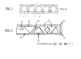
- FIG. 1 A typical cross-section of a hollow core slab is presented in figure 1 .
- the prestressing strands are represented by the black dots.
- the orientation of the concrete webs between the continuous voids of existing concrete hollow core slabs is mainly vertical. Only the orientation of the two outer webs is not mainly vertical because space is needed for a product specific clamp to lift the slabs and to facilitate in-situ making of a joint between the slabs.
- the shape of the voids of existing concrete hollow core slabs is for example circular, rectangular or elliptical.
- the slabs are significantly rounded off at their bottom corners. At least one of the reasons for doing so is to improve the visual appearance of a floor made up of hollow core slabs in which the vertical deformation of at least one of the slabs is larger than the deformation of the other slabs.
- Figure 1 is only illustrative.
- a novel hollow core slab having improved fire resistance which is achieved by providing the hollow core slab, i.e. the precast slab of prestressed concrete, including, in span direction, a plurality of mainly parallel voids and concrete webs between said voids, with one or more constructive elements, including means, dimensions, shapes, cross-sections and/or further arrangements for reducing the load on the webs and/or for increasing the resistance of the webs of the hollow core slab in case of fire, i.e. exposure to heat of the external surface of the bottom flange of the slab.
- the hollow core slab i.e. the precast slab of prestressed concrete, including, in span direction, a plurality of mainly parallel voids and concrete webs between said voids, with one or more constructive elements, including means, dimensions, shapes, cross-sections and/or further arrangements for reducing the load on the webs and/or for increasing the resistance of the webs of the hollow core slab in case of fire, i.e. exposure to heat of the external surface of the
- one or more constructive elements of the novel hollow core slab according to the invention include means, dimensions, shapes, cross-sections and/or further arrangements and/or configurations for reducing the shear and/or bending force in said webs and/or for increasing the shear and/or bending resistance or capacity of said webs.
- one or more constructive elements of the novel hollow core slab according to the invention include at least one of the following elements:
- Figure 1 shows the cross-section of a prior art hollow core slab, wherein the concrete slab 1 includes prestressing strands 2, as well as a number of voids 3 and concrete webs 4 or wall between the voids.
- the main direction of the webs 4 is mainly vertical, i.e. perpendicular to the (horizontal) top and bottom layers, called top flange 5 and bottom flange 6 respectively.
- horizontal cracks may originate when exposed to a fire (in an area below the hollow core slab).
- These horizontal cracks will occur, already in an early stage of the fire, due to the occurrence of shear and/or bending forces in said webs which exceed the shear and/or bending resistance (capacity) of these webs.
- the invention includes a novel hollow core slab configuration which -in order to counteract or prevent that, like in the prior art configuration, the shear and/or bending forces in the webs occurring during fire, will exceed the shear and/or bending resistance of those webs in a (too) early stage- include means, dimensions, shapes, cross-sections and/or further arrangements or configurations for reducing the shear and/or bending force in said webs and/or for increasing the shear and/or bending resistance or capacity of said webs.
- Figure 2 shows schematically a number of exemplary embodiments of such means, dimensions, shapes, cross-sections and/or further arrangements or configurations for reducing the shear and/or bending force in said webs and/or for increasing the shear and/or bending resistance or capacity of said webs, which will be discussed in the following point by point.
- a first preferred elaboration of the present invention concerns a cross-sectional shape consisting of a bottom and a top flange that are connected by at least two webs that have a more or less opposite, non-vertical orientation, see item 11 in figure 2 , which possibly could be completed with some mainly vertically oriented webs.
- the cross-section contains two or more webs that have a non-vertical orientation and together with at least a part of the bottom or the top flange form the shape of at least one triangle.
- the hollow cores are triangular or diamond-shaped.
- the corners of the hollow cores are rounded off.
- the cross-sectional shape concerns a truss comprising one or more triangular units.
- This first preferred elaboration is advantageous depending on the specific design of the hollow core slab, for example the thickness of the "hot” flange and the webs, the height and orientation of the webs and the length of the "hot” flange between the webs.
- This first preferred elaboration is advantageous when the increase of the capacity (i.e. the resistance) of the webs to resist horizontal forces, due to for example the fact that the non-vertical webs are loaded less on shear and bending and more on normal force than the vertical webs, is larger than the increase of the horizontal forces due to the fact that the non-vertical webs behave stiffer than the vertical webs.
- a second preferred elaboration of the present invention concerns expansion joints in the "hot” or “cold” flange of the hollow core slabs or in the compression layer if present, see item 12 in figure 2 .
- the expansion joints may be positioned anywhere in the "hot” or “cold” flanges and may be applied partially or fully (not drawn) through the thickness of the flanges.
- the expansion joints that are applied partially through the thickness of the flanges may be applied from the exterior surface of the hollow core slab or from the hollow cores.
- the expansion joints can be continuous over the length of the hollow core slab. Discontinuous expansion joints are not excluded.
- Expansion joints can be applied to hollow core slabs that have already been applied in existing buildings and to hollow core slabs that still have to be produced. Expansion joints may be filled with a material that has a low modulus of elasticity compared to that of concrete. The mechanical stress in this material is therefore negligible during fire.
- the expansion joints may also be filled with a material whose modulus of elasticity is comparable to that of concrete in case the material is cold and whose modulus of elasticity decreases significantly when it is heated during fire. The mechanical stress in this material is therefore negligible during fire.
- This second preferred elaboration is especially advantageous because it reduces the compressive force in the "hot” flange and the tensile force in the "cold” flange, and in the compression layer if present, thereby reducing the forces in the webs. Expansion joints can even force harmless vertical cracks in the flanges and the compression layer thereby preventing harmful horizontal cracks in the webs.
- a third preferred elaboration of the present invention concerns a non-homogeneous material distribution in the cross-section of the hollow core slab, two or more types of concrete are used anywhere in the cross-section, see item 13 in figure 2 where the cross-section is for example made up of four types of concrete with different properties.
- the "hot" flange is made of a concrete that has a low modulus of elasticity and/or tensile and/or compressive strength and/or thermal expansion coefficient. This is especially advantageous because it reduces the load on the webs when the "hot" flange is heated by a fire.
- a different concrete for the outer webs is for example advantageous when the bottom corners are significantly rounded off, the outer edges are not vertical and the outer cores have a normal size, which is often the case for prior art hollow core slabs and causes a relatively high bending moment in the outer webs during fire.
- a concrete with a high modulus of elasticity is used when the disadvantages of a stiffer concrete, causing an increase of load in the outer webs, do not weigh up against the advantages of the higher tensile strength, causing an increase of capacity of the outer webs.
- Using a different concrete for the "cold" web is for example advantageous when a low tensile strength forces a vertical crack in a part of the "cold" flange that is loaded under tension during fire, thereby preventing harmful horizontal cracks in the webs.
- a fourth preferred elaboration of the present invention concerns smaller outer cores that are positioned against the "cold" flange, see item 14 in figure 2 .
- These cores can have any shape.
- the cores are rounded off to prevent peak tensile stresses causing localized horizontal cracks in the outer webs. In item 14 in figure 2 this is clearly not the case.
- This fourth preferred elaboration is advantageous when the increase of the capacity of outer webs to resist horizontal forces, due to the fact that the outer webs contain more concrete and/or have an improved mechanical connection with at least one of the inner webs, is larger than the increase of the horizontal forces due to the fact that the outer webs behave stiffer.
- a fifth preferred elaboration of the present invention concerns the use of very wide outer webs or the absence of the outer cores and is not presented in figure 2 .
- An outer core is absent or an outer web is very wide when the minimum width of the outer web is three times the minimum width of the inner web with the smallest width.
- Using very wide webs or the absence of the outer cores is especially advantageous when the bottom corners of the hollow core slab are significantly rounded off and/or the outer edges are not vertical, which is the case for prior art hollow core slabs and causes a relatively high bending moment in the outer webs, potentially causing horizontal cracks
- This fifth preferred elaboration is advantageous when the increase of the capacity of outer webs to resist horizontal forces, due to the fact that the outer webs are wider, is larger than the increase of the horizontal forces due to the fact that the outer webs behave stiffer.
- a sixth preferred elaboration of the present invention concerns the use of bottom corners that are not significantly rounded off and is presented as item 16 in figure 2 .
- the height of the side of the "hot" flange which is not to come into (butt) contact with other slabs or any other building structure, e.g. by rounding off or bevelling, preferably has a maximum of about 10 mm, more preferably of about 5 mm.
- bottom corners that are not significantly rounded off is advantageous because this reduces the forces in the outer webs, especially the bending moment, because the compressive force in the "hot" flange does not need to be transferred vertically in the outer web before it can be transferred horizontally to the "hot” flange of the next hollow core slab.
- a seventh preferred elaboration concerns the use of vertical outer edges and is presented as item 17 in figure 2 .
- the top corners of the vertical outer edges may be rounded off and small spaces for product specific clamps to lift the slabs may be applied (not drawn). These spaces should be located in the upper half of the slab.
- the vertical outer edges of two adjacent slabs may be positioned directly against each other when a large contact surface can be achieved in practice.
- the hollow core slabs with vertical outer edges may also be placed at a distance that is preferably as small as possible. In this case the joint should be filled with a material that has mechanical properties comparable to the properties of the concrete used for the hollow core slabs.
- the reinforcement may consist of reinforcement bars or grids.
- Reinforcement bars or grids are preferably positioned on top of the prestressing strands.
- the reinforcement bars or grids are positioned at a regular distance in span direction of the hollow core slab.
- the reinforcement bars or grids are positioned in the colder top part of the "hot" flange.
- Having reinforcement in the "hot” flange is advantageous because it reduces the horizontal forces in the webs due to the fact that the internal resistance against expansion of the "hot” flange increases. Having reinforcement in the "hot” flange is furthermore advantageous because this can prevent the occurrence of horizontal cracks in the webs, depending on the specific design of a hollow core slab, due to the fact that the webs remain supported by the "hot” flange due to the prevention of vertical cracks in the "hot” flange or due to the prevention of decomposition of the "hot” flange, by the reinforcement.
- a ninth preferred elaboration of the present invention concerns the use of reinforcement in the webs and is presented as item 19 in figure 2 .
- the reinforcement may consist of reinforcement bars or grids.
- Preferably the reinforcement extends into the "hot” and/or "cold” flanges.
- Having reinforcement in the webs is advantageous when the disadvantages of a stiffer web, causing an increase of load in the webs, do not weigh up against the advantages of the increase of capacity of the webs, in case the concrete of the webs is cracked or not cracked.
Landscapes
- Engineering & Computer Science (AREA)
- Architecture (AREA)
- Civil Engineering (AREA)
- Structural Engineering (AREA)
- Building Environments (AREA)
Abstract
Hollow core slab comprising a top flange (14) and a bottom flange (18), a plurality of voids and webs (11) between said voids, said webs (11) extending between said bottom (18) and top (14) flange. The hollow core slab is provided with one or more constructive elements for reducing the shear and/or bending force in the webs and/or for increasing the shear and/or bending resistance or capacity of the webs. Such constructive elements may comprise e.g. non-vertical webs (11), expansion joints (12), non-homogeneous material distribution (13) in the slab, small outer cores, preferably positioned at the side of the top flange (14), wide outer webs and/or absence of outer cores, bottom comer not significantly rounded off (16), vertical outer edges (17), reinforcement means (18) in the bottom flange, reinforcement means (19) in at least part of the webs.
Description
- This invention refers to a hollow core slab, defined as a precast slab of prestressed concrete, including, in span direction, a plurality of mainly parallel voids and concrete webs between said voids.
- Hollow core slabs have been used widely throughout the past three decades for flooring, roofing and occasionally for walls. They have been applied in buildings like hotels, offices, cinemas, car parks and shopping centres. Hollow core slabs are used in favour of conventional reinforced concrete slabs because their weight is significantly lower and considerably larger spans can be achieved. This results in significant overall savings in construction costs, as the load bearing structure can be constructed lighter. This again leads to reduced dimensions of the foundations. Another advantage of hollow core slabs with respect to conventional reinforced concrete slabs is that the construction time is shorter.
- In order to construct a floor, concrete is poured in the joints between the hollow core slabs, which can be positioned beside and/or behind each other, and are supported by a load bearing structure. The joints are often filled with concrete that has a lower modulus of elasticity than the concrete that is used for the hollow core slabs. Hollow core slabs may be strengthened by additional concrete that is poured in the hollow cores or against one or more of the external surfaces. When a hollow core slab is used for flooring a concrete compression layer may e.g. be poured in-situ on top of the hollow core slab. This layer may contain reinforcement. Furthermore special connection means, for example anchors, may be used to connect the hollow core slab with the supporting or surrounding load bearing structure. These anchors are often partly incorporated in the concrete that is poured in the hollow cores.
- A typical cross-section of a hollow core slab is presented in
figure 1 . The prestressing strands are represented by the black dots. The orientation of the concrete webs between the continuous voids of existing concrete hollow core slabs is mainly vertical. Only the orientation of the two outer webs is not mainly vertical because space is needed for a product specific clamp to lift the slabs and to facilitate in-situ making of a joint between the slabs. The shape of the voids of existing concrete hollow core slabs is for example circular, rectangular or elliptical. The slabs are significantly rounded off at their bottom corners. At least one of the reasons for doing so is to improve the visual appearance of a floor made up of hollow core slabs in which the vertical deformation of at least one of the slabs is larger than the deformation of the other slabs.Figure 1 is only illustrative. - Recent research and fire damage have shown that the fire resistance with regard to the load bearing function of at least some existing hollow core slab types is significantly lower than their expected fire resistance based on tests and design calculations according to international standards. This is thought to be caused by horizontal cracks in the webs of the hollow core slab that already occur during a very early stage of the fire. Due to these horizontal cracks the slab subdivides in two parts. In one case, where hollow core slabs where used for flooring, these horizontal cracks lead to an early collapse of the bottom part of the hollow core slab floor, almost killing firemen. These horizontal cracks were rarely seen during tests performed according to international standards. In fire tests often vertical cracks occur in the flanges, at the position where the height of the flanges is least, instead of horizontal cracks in the webs. These vertical cracks are relatively harmless compared to the horizontal cracks because the vertical cracks only subdivide the hollow core slab into separate beams. Further discussion of the problems experienced with the fire resistance of existing hollow core slabs can be found at www.verenigingbwt.nl/ufc/file/bwti_sites/4816d782a86107dec06632afdb8a12f2/pu/Rapport_Rotterda m_parkeergarage_I.pdf.
- Where, in this application, is spoken of horizontal and vertical respectively, it must be understood that in most applications the hollow core slabs are installed as a floor in (mainly) horizontal position, i.e. the top flange and the bottom flange will extend mainly horizontally. When a fire occurs, the bottom flange will be the "hot flange" and the top flange will be the "cold flange". When, however, hollow core slabs would be mounted in upright position as a wall, the "hot flange" may be formed by one of both sides and the "cold flange" by the other side. Where appropriate, the notions "hot flange and "bottom flange" will be considered, in this patent application, as having the same meaning and implication and those notions are mutually interchangeable. The same applies, mutates mutandis, for the notions "cold flange" and "top flange".
- According to the present invention a novel hollow core slab is proposed having improved fire resistance which is achieved by providing the hollow core slab, i.e. the precast slab of prestressed concrete, including, in span direction, a plurality of mainly parallel voids and concrete webs between said voids, with one or more constructive elements, including means, dimensions, shapes, cross-sections and/or further arrangements for reducing the load on the webs and/or for increasing the resistance of the webs of the hollow core slab in case of fire, i.e. exposure to heat of the external surface of the bottom flange of the slab.
- More specifically, it is preferred that one or more constructive elements of the novel hollow core slab according to the invention include means, dimensions, shapes, cross-sections and/or further arrangements and/or configurations for reducing the shear and/or bending force in said webs and/or for increasing the shear and/or bending resistance or capacity of said webs.
- It is preferred that one or more constructive elements of the novel hollow core slab according to the invention, include at least one of the following elements:
- one or more, preferably two or more mainly non-square webs, where non-square is defined as non-perpendicular to the planes of the top and bottom flanges;
- one or more expansion joints;
- non-homogeneous material distribution in the slab;
- small outer cores, preferably positioned at the side of the top flange;
- wide outer webs and/or absence of outer cores;
- side edges not significantly rounded off or bevelled;
- mainly square outer edges, where square is defined as perpendicular to the planes of the flanges;
- reinforcement means in the bottom flange;
- reinforcement means in at least part of the webs.
- Hereinafter the present invention will be discussed more in detail with reference to some figures.
- Figure 1
- shows a prior art hollow core slab in cross-sectional view;
- Figure 2
- shows an exemplary embodiment of the novel hollow core slab in cross-sectional view.
-
Figure 1 shows the cross-section of a prior art hollow core slab, wherein theconcrete slab 1 includesprestressing strands 2, as well as a number ofvoids 3 and concrete webs 4 or wall between the voids. As can be seen the main direction of the webs 4 is mainly vertical, i.e. perpendicular to the (horizontal) top and bottom layers, called top flange 5 and bottom flange 6 respectively. In these vertical webs horizontal cracks may originate when exposed to a fire (in an area below the hollow core slab). These horizontal cracks will occur, already in an early stage of the fire, due to the occurrence of shear and/or bending forces in said webs which exceed the shear and/or bending resistance (capacity) of these webs. - As mentioned in the previous text the invention includes a novel hollow core slab configuration which -in order to counteract or prevent that, like in the prior art configuration, the shear and/or bending forces in the webs occurring during fire, will exceed the shear and/or bending resistance of those webs in a (too) early stage- include means, dimensions, shapes, cross-sections and/or further arrangements or configurations for reducing the shear and/or bending force in said webs and/or for increasing the shear and/or bending resistance or capacity of said webs.
-
Figure 2 shows schematically a number of exemplary embodiments of such means, dimensions, shapes, cross-sections and/or further arrangements or configurations for reducing the shear and/or bending force in said webs and/or for increasing the shear and/or bending resistance or capacity of said webs, which will be discussed in the following point by point. - A first preferred elaboration of the present invention concerns a cross-sectional shape consisting of a bottom and a top flange that are connected by at least two webs that have a more or less opposite, non-vertical orientation, see
item 11 infigure 2 , which possibly could be completed with some mainly vertically oriented webs. Preferably the cross-section contains two or more webs that have a non-vertical orientation and together with at least a part of the bottom or the top flange form the shape of at least one triangle. Preferably the hollow cores are triangular or diamond-shaped. Preferably the corners of the hollow cores are rounded off. Preferably the cross-sectional shape concerns a truss comprising one or more triangular units. - This first preferred elaboration is advantageous depending on the specific design of the hollow core slab, for example the thickness of the "hot" flange and the webs, the height and orientation of the webs and the length of the "hot" flange between the webs. This first preferred elaboration is advantageous when the increase of the capacity (i.e. the resistance) of the webs to resist horizontal forces, due to for example the fact that the non-vertical webs are loaded less on shear and bending and more on normal force than the vertical webs, is larger than the increase of the horizontal forces due to the fact that the non-vertical webs behave stiffer than the vertical webs.
- A second preferred elaboration of the present invention concerns expansion joints in the "hot" or "cold" flange of the hollow core slabs or in the compression layer if present, see
item 12 infigure 2 . The expansion joints may be positioned anywhere in the "hot" or "cold" flanges and may be applied partially or fully (not drawn) through the thickness of the flanges. The expansion joints that are applied partially through the thickness of the flanges may be applied from the exterior surface of the hollow core slab or from the hollow cores. The expansion joints can be continuous over the length of the hollow core slab. Discontinuous expansion joints are not excluded. Expansion joints can be applied to hollow core slabs that have already been applied in existing buildings and to hollow core slabs that still have to be produced. Expansion joints may be filled with a material that has a low modulus of elasticity compared to that of concrete. The mechanical stress in this material is therefore negligible during fire. - The expansion joints may also be filled with a material whose modulus of elasticity is comparable to that of concrete in case the material is cold and whose modulus of elasticity decreases significantly when it is heated during fire. The mechanical stress in this material is therefore negligible during fire.
- This second preferred elaboration is especially advantageous because it reduces the compressive force in the "hot" flange and the tensile force in the "cold" flange, and in the compression layer if present, thereby reducing the forces in the webs. Expansion joints can even force harmless vertical cracks in the flanges and the compression layer thereby preventing harmful horizontal cracks in the webs.
- A third preferred elaboration of the present invention concerns a non-homogeneous material distribution in the cross-section of the hollow core slab, two or more types of concrete are used anywhere in the cross-section, see
item 13 infigure 2 where the cross-section is for example made up of four types of concrete with different properties. - Preferably the "hot" flange is made of a concrete that has a low modulus of elasticity and/or tensile and/or compressive strength and/or thermal expansion coefficient. This is especially advantageous because it reduces the load on the webs when the "hot" flange is heated by a fire.
- It can be advantageous to use a different concrete for the outer webs, with a different modulus of elasticity and/or tensile and/or compressive strength, depending on the design of a specific hollow core slab, especially the absence of outer cores (see paragraph e.), the size and position of the outer cores (see paragraph d), the fact whether the bottom corners are significantly rounded off or not (see paragraph f), and the outer edges are vertical or not (see paragraph g).
- Using a different concrete for the outer webs is for example advantageous when the bottom corners are significantly rounded off, the outer edges are not vertical and the outer cores have a normal size, which is often the case for prior art hollow core slabs and causes a relatively high bending moment in the outer webs during fire. In this example it depends on the specific design of the hollow core slab whether a concrete with a high modulus of elasticity, tensile and compressive strength, or a concrete with a low modulus of elasticity, tensile and compressive strength, is advantageous. In this example a concrete with a high modulus of elasticity is used when the disadvantages of a stiffer concrete, causing an increase of load in the outer webs, do not weigh up against the advantages of the higher tensile strength, causing an increase of capacity of the outer webs.
- It can be advantageous to use a different concrete for the "cold" flange, with a different modulus of elasticity and/or tensile and/or compressive strength than the concrete that is used for the webs, depending on the design of a specific hollow core slab, for example the specific shape of the truss as mentioned in paragraph a.
- Using a different concrete for the "cold" web is for example advantageous when a low tensile strength forces a vertical crack in a part of the "cold" flange that is loaded under tension during fire, thereby preventing harmful horizontal cracks in the webs.
- A fourth preferred elaboration of the present invention concerns smaller outer cores that are positioned against the "cold" flange, see
item 14 infigure 2 . These cores can have any shape. Preferably the cores are rounded off to prevent peak tensile stresses causing localized horizontal cracks in the outer webs. Initem 14 infigure 2 this is clearly not the case. - Using smaller outer cores that are positioned against the "cold" flange is especially advantageous when the bottom corners of the hollow core slab are significantly rounded off and/or the outer edges are not vertical, which is the case for prior art hollow core slabs and causes a relatively high bending moment in the outer webs, potentially causing horizontal cracks
- This fourth preferred elaboration is advantageous when the increase of the capacity of outer webs to resist horizontal forces, due to the fact that the outer webs contain more concrete and/or have an improved mechanical connection with at least one of the inner webs, is larger than the increase of the horizontal forces due to the fact that the outer webs behave stiffer.
- A fifth preferred elaboration of the present invention concerns the use of very wide outer webs or the absence of the outer cores and is not presented in
figure 2 . An outer core is absent or an outer web is very wide when the minimum width of the outer web is three times the minimum width of the inner web with the smallest width. Using very wide webs or the absence of the outer cores is especially advantageous when the bottom corners of the hollow core slab are significantly rounded off and/or the outer edges are not vertical, which is the case for prior art hollow core slabs and causes a relatively high bending moment in the outer webs, potentially causing horizontal cracks - This fifth preferred elaboration is advantageous when the increase of the capacity of outer webs to resist horizontal forces, due to the fact that the outer webs are wider, is larger than the increase of the horizontal forces due to the fact that the outer webs behave stiffer.
- A sixth preferred elaboration of the present invention concerns the use of bottom corners that are not significantly rounded off and is presented as
item 16 infigure 2 . The height of the side of the "hot" flange which is not to come into (butt) contact with other slabs or any other building structure, e.g. by rounding off or bevelling, preferably has a maximum of about 10 mm, more preferably of about 5 mm. - Having bottom corners that are not significantly rounded off is advantageous because this reduces the forces in the outer webs, especially the bending moment, because the compressive force in the "hot" flange does not need to be transferred vertically in the outer web before it can be transferred horizontally to the "hot" flange of the next hollow core slab.
- A seventh preferred elaboration concerns the use of vertical outer edges and is presented as item 17 in
figure 2 . The top corners of the vertical outer edges may be rounded off and small spaces for product specific clamps to lift the slabs may be applied (not drawn). These spaces should be located in the upper half of the slab. The vertical outer edges of two adjacent slabs may be positioned directly against each other when a large contact surface can be achieved in practice. The hollow core slabs with vertical outer edges may also be placed at a distance that is preferably as small as possible. In this case the joint should be filled with a material that has mechanical properties comparable to the properties of the concrete used for the hollow core slabs. - Having vertical outer edges is especially advantageous when the bottom corners of the hollow core slabs are rounded off and outer hollow cores of normal size are present, which is often the case for prior art hollow core slabs.
- In this case filling of the joints with a material of which the modulus of elasticity and compressive strength is lower than that of the concrete used for the hollow core slabs, which is mostly the case in current practice, increases the bending moment in the outer webs because the stiffness of the horizontal support of the outer webs decreases. Furthermore the horizontal force will be transferred more concentrated through the bottom part of the joints. This effect is strengthened when the shape of the joint is non-vertical and causes an increase of tensile stresses in the outer webs possibly causing horizontal cracks in the webs. Therefore it is advantageous to have vertical outer edges.
- An eighth preferred elaboration of the present invention concerns the use of reinforcement in the "hot" flange and is presented as
item 18 infigure 2 . The reinforcement may consist of reinforcement bars or grids. Reinforcement bars or grids are preferably positioned on top of the prestressing strands. Preferably the reinforcement bars or grids are positioned at a regular distance in span direction of the hollow core slab. Preferably the reinforcement bars or grids are positioned in the colder top part of the "hot" flange. - Having reinforcement in the "hot" flange is advantageous because it reduces the horizontal forces in the webs due to the fact that the internal resistance against expansion of the "hot" flange increases. Having reinforcement in the "hot" flange is furthermore advantageous because this can prevent the occurrence of horizontal cracks in the webs, depending on the specific design of a hollow core slab, due to the fact that the webs remain supported by the "hot" flange due to the prevention of vertical cracks in the "hot" flange or due to the prevention of decomposition of the "hot" flange, by the reinforcement.
- A ninth preferred elaboration of the present invention concerns the use of reinforcement in the webs and is presented as
item 19 infigure 2 . The reinforcement may consist of reinforcement bars or grids. Preferably the reinforcement extends into the "hot" and/or "cold" flanges. - Having reinforcement in the webs is advantageous when the disadvantages of a stiffer web, causing an increase of load in the webs, do not weigh up against the advantages of the increase of capacity of the webs, in case the concrete of the webs is cracked or not cracked.
Claims (29)
- Hollow core slab (1), defined as a precast slab of prestressed concrete, including a first layer or flange, called first flange (5) hereinafter, and a second layer or flange, called second flange (6) hereinafter, a plurality of mainly parallel hollow cores or voids, called voids (3) hereinafter, and walls or webs, called webs (4) hereinafter, located between said voids and extending between said first flange and second flange,
wherein the hollow core slab is provided with one or more constructive elements, including means, dimensions, shapes, cross-sections and/or further arrangements for reducing the load on the webs and/or for increasing the resistance of the webs of the hollow core slab in case of fire, i.e. exposure of mainly one exterior surface of the slab to heat. - Hollow core slab according to claim 1, wherein one or more of said constructive elements of the hollow core slab include means, dimensions, shapes, cross-sections and/or further arrangements for reducing the shear and/or bending force in said webs and/or for increasing the shear and/or bending resistance or capacity of said webs.
- Hollow core slab according to claim 1 or 2, wherein one or more of said constructive elements of the hollow core slab according to the invention, include at least one of the following elements:- one or more, preferably two or more mainly non-square webs (11), where non-square is defined as non-perpendicular to the planes of the first and second flanges;- one or more expansion joints (12);- non-homogeneous material distribution (13) in the slab;- small outer cores, preferably positioned at the side of the first flange (14);- wide outer webs and/or absence of outer cores;- side edges not significantly rounded off or bevelled (16);- mainly square outer edges (17), where square is defined as perpendicular to the planes of the first and second flanges;- reinforcement means (18) in the second flange;- reinforcement means (19) in at least part of the webs.
- Hollow core slab according to any preceding claim, wherein the cross-sectional shape of the slab comprises a first flange and second flange which are interconnected by webs (11) having a mainly non-square orientation.
- Hollow core slab according to claim 4, wherein the cross-section comprises two or more webs having a mainly non-square orientation and at least part of the first flange or second flange forming the shape of at least one triangle.
- Hollow core slab according to claim 4, wherein at least part of the voids are triangular or diamond-shaped.
- Hollow core slab according to claim 6, wherein the corners of at least part of the voids are rounded off.
- Hollow core slab according to claim 6, wherein the cross-sectional shape includes a truss comprising one or more triangular units.
- Hollow core slab according to any preceding claim, comprising one or more expansion joints (12) in the first flange or second flange of the hollow core slab and/or in an additional or attached compression layer, said one or more expansion joints (12) extending over at least part of the length and/or width of the slab and/or the compression layer.
- Hollow core slab according to claim 9, said one or more expansion joints extending over at least part of the thickness of the material between the outer side of the first flange and/or second flange and relevant voids.
- Hollow core slab according to claim 9 or 10, said one or more expansion joints extending from the outer side of the first flange and/or second flange and/or from their inner sides, e.g. from one or more voids.
- Hollow core slab according to any of claims 9-11, wherein at least part of the expansion joints are at least partly filled with a material having a relatively low modulus of elasticity compared to that of concrete.
- Hollow core slab according to any of claims 9 - 11, wherein at least part of the expansion joints are at least partly filled with a material having a modulus of elasticity which is comparable to that of concrete in case the material is cold and whose modulus of elasticity decreases significantly when it is heated during fire.
- Hollow core slab according to any preceding claim, wherein the slab has a non-homogeneous material distribution (13) over the cross-section and/or over the width and/or over the length of the hollow core slab, e.g. by using two or more types of concrete at different slab locations.
- Hollow core slab according to claim 14, wherein the second flange is made of a concrete having a low modulus of elasticity and/or tensile strength and/or compressive strength and/or thermal expansion coefficient.
- Hollow core slab according to claim 14, wherein a different concrete is used for the inner and outer webs respectively, having different moduli of elasticity and/or tensile strengths and/or compressive strengths
- Hollow core slab according to any preceding claim, comprising outer voids (14) having smaller cross-sectional areas than the voids located more inwardly.
- Hollow core slab according to claim 17, said outer voids being located more towards the plane of the first flange than the voids located more inwardly.
- Hollow core slab according to any preceding claim, comprising very wide outer webs and/or absence of outer voids, said outer webs having a substantial larger cross-section thickness than the webs located more inwardly.
- Hollow core slab according to claim 19, wherein the minimum width of the outer web is at least twice, preferably, three times the minimum width of the webs located more inwardly.
- Hollow core slab according to any preceding claim, wherein at least part of the bottom corners (16) of the slab are not significantly rounded off or bevelled.
- Hollow core slab according to claim 21, wherein the rounding or bevelling of the slab at the relevant side edge or edges (16) has a maximum of 10 mm, preferably 5 mm.
- Hollow core slab according to any preceding claim, comprising mainly square outer edges (17).
- Hollow core slab according to any preceding claim, wherein the second flange comprises reinforcement means (18), e.g. reinforcement bars and/or reinforcement grids.
- Hollow core slab according to claim 24, comprising reinforcement bars and/or reinforcement grids positioned on top of prestressing strands (2).
- Hollow core slab according to claim 24 or 25, said reinforcement bars and/or reinforcement grids being positioned at regular distance in span direction of the slab.
- Hollow core slab according to any of claims 24 - 26, said reinforcement bars and/or reinforcement grids being positioned in the inside part of the second flange.
- Hollow core slab according to any preceding claim, wherein at least part of the webs comprise reinforcement means (19) in the webs, e.g. reinforcement bars and/or reinforcement grids.
- Hollow core slab according to claim 28, wherein said reinforcement means extend to the second flange and/or the first flange.
Priority Applications (3)
| Application Number | Priority Date | Filing Date | Title |
|---|---|---|---|
| EP09170369A EP2299020A1 (en) | 2009-09-15 | 2009-09-15 | Hollow core slab with improved fire resistance |
| PCT/NL2010/050593 WO2011034420A1 (en) | 2009-09-15 | 2010-09-15 | Hollow core slab with improved fire resistance |
| EP10760124A EP2478165A1 (en) | 2009-09-15 | 2010-09-15 | Hollow core slab with improved fire resistance |
Applications Claiming Priority (1)
| Application Number | Priority Date | Filing Date | Title |
|---|---|---|---|
| EP09170369A EP2299020A1 (en) | 2009-09-15 | 2009-09-15 | Hollow core slab with improved fire resistance |
Publications (1)
| Publication Number | Publication Date |
|---|---|
| EP2299020A1 true EP2299020A1 (en) | 2011-03-23 |
Family
ID=41401811
Family Applications (1)
| Application Number | Title | Priority Date | Filing Date |
|---|---|---|---|
| EP09170369A Withdrawn EP2299020A1 (en) | 2009-09-15 | 2009-09-15 | Hollow core slab with improved fire resistance |
Country Status (1)
| Country | Link |
|---|---|
| EP (1) | EP2299020A1 (en) |
Cited By (2)
| Publication number | Priority date | Publication date | Assignee | Title |
|---|---|---|---|---|
| CN107254930A (en) * | 2017-08-04 | 2017-10-17 | 徐焱 | A kind of wide cut hollow superimposed sheet |
| CN117432122A (en) * | 2023-10-27 | 2024-01-23 | 上海城建建设实业集团新型建筑材料嘉兴有限公司 | Prestressed hollow slab |
Citations (6)
| Publication number | Priority date | Publication date | Assignee | Title |
|---|---|---|---|---|
| FR1313240A (en) * | 1961-11-15 | 1962-12-28 | building elements | |
| GB1264771A (en) * | 1970-01-01 | 1972-02-23 | ||
| DE2754675A1 (en) * | 1977-12-08 | 1979-06-13 | Wilhelm Johannes Di Silberkuhl | Roof and ceiling structure load-bearing box unit - comprises half box reinforced concrete elements offset through half circle and joined (NL 12.6.79) |
| DE4007977A1 (en) * | 1989-03-16 | 1990-10-11 | 43 Sz Allami Epitoeipari Valla | Concrete panels for ceilings - have moulded ducts to receive electric cables |
| GB2268946A (en) * | 1992-07-23 | 1994-01-26 | Kuldip Singh Randhawa | Prestressing of concrete composite sections |
| EP1146180A1 (en) * | 2000-04-12 | 2001-10-17 | Ute Huk | Process for constructing a concrete floor element and concrete floor element |
-
2009
- 2009-09-15 EP EP09170369A patent/EP2299020A1/en not_active Withdrawn
Patent Citations (6)
| Publication number | Priority date | Publication date | Assignee | Title |
|---|---|---|---|---|
| FR1313240A (en) * | 1961-11-15 | 1962-12-28 | building elements | |
| GB1264771A (en) * | 1970-01-01 | 1972-02-23 | ||
| DE2754675A1 (en) * | 1977-12-08 | 1979-06-13 | Wilhelm Johannes Di Silberkuhl | Roof and ceiling structure load-bearing box unit - comprises half box reinforced concrete elements offset through half circle and joined (NL 12.6.79) |
| DE4007977A1 (en) * | 1989-03-16 | 1990-10-11 | 43 Sz Allami Epitoeipari Valla | Concrete panels for ceilings - have moulded ducts to receive electric cables |
| GB2268946A (en) * | 1992-07-23 | 1994-01-26 | Kuldip Singh Randhawa | Prestressing of concrete composite sections |
| EP1146180A1 (en) * | 2000-04-12 | 2001-10-17 | Ute Huk | Process for constructing a concrete floor element and concrete floor element |
Cited By (3)
| Publication number | Priority date | Publication date | Assignee | Title |
|---|---|---|---|---|
| CN107254930A (en) * | 2017-08-04 | 2017-10-17 | 徐焱 | A kind of wide cut hollow superimposed sheet |
| CN107254930B (en) * | 2017-08-04 | 2023-09-08 | 徐焱 | Broad-width hollow superimposed sheet |
| CN117432122A (en) * | 2023-10-27 | 2024-01-23 | 上海城建建设实业集团新型建筑材料嘉兴有限公司 | Prestressed hollow slab |
Similar Documents
| Publication | Publication Date | Title |
|---|---|---|
| US5099628A (en) | Apparatus for enhancing structural integrity of masonry structures | |
| KR101152270B1 (en) | Precast concrete slab system for building which have long span and require high design load and construction method using this system | |
| US8733050B2 (en) | Compressive force transmitting connection element | |
| EP0996795B1 (en) | Composite steel/concrete column | |
| Lai | Structural behavior of BubbleDeck® slabs and their application to lightweight bridge decks | |
| KR20090013830A (en) | Structural elements and how to use them | |
| KR101533576B1 (en) | Composite beam having truss reinforcement embedded in a concrete | |
| US20100170183A1 (en) | Reinforced load bearing structure | |
| MX2007008487A (en) | Composite energy absorbing structure. | |
| KR20100100711A (en) | T-typed precast concrete slab and contstruction method thereof | |
| US10640970B2 (en) | Concrete building elements and assemblies thereof, and related methods | |
| KR102382352B1 (en) | Composite column and composite column structure | |
| JP7098646B2 (en) | Bubble concrete composite building material | |
| CN112962843A (en) | Construction method for assembling construction sound insulation heat preservation form-removal-free concrete floor | |
| US20240368885A1 (en) | Composite foam-glass elements and use thereof | |
| CN110644618B (en) | Post-tensioned prestressing assembled concrete superposed beam steel bar structure and design method thereof | |
| CN110206164B (en) | Connecting structure of steel plate-encased concrete composite shear wall and concrete floor slab and construction method thereof | |
| CN211037391U (en) | Shear wall structure for optimizing stress distribution | |
| US20110258949A1 (en) | Prestressed slab element | |
| KR20100022703A (en) | Composite slab using deck plate made by glass fiber reinforced polymer | |
| CN110468953A (en) | Assembling type steel structure and assembled architecture | |
| CN117386066A (en) | A kind of prefabricated UHPC beam component and beam-plate connection structure | |
| KR100887706B1 (en) | Spacer embedded in slab and slab using same | |
| EP3480376B1 (en) | Flooring system | |
| WO2011034420A1 (en) | Hollow core slab with improved fire resistance |
Legal Events
| Date | Code | Title | Description |
|---|---|---|---|
| PUAI | Public reference made under article 153(3) epc to a published international application that has entered the european phase |
Free format text: ORIGINAL CODE: 0009012 |
|
| AK | Designated contracting states |
Kind code of ref document: A1 Designated state(s): AT BE BG CH CY CZ DE DK EE ES FI FR GB GR HR HU IE IS IT LI LT LU LV MC MK MT NL NO PL PT RO SE SI SK SM TR |
|
| AX | Request for extension of the european patent |
Extension state: AL BA RS |
|
| STAA | Information on the status of an ep patent application or granted ep patent |
Free format text: STATUS: THE APPLICATION IS DEEMED TO BE WITHDRAWN |
|
| 18D | Application deemed to be withdrawn |
Effective date: 20110924 |