EP2298640A1 - Ducted pre-swirl stator assembly - Google Patents
Ducted pre-swirl stator assembly Download PDFInfo
- Publication number
- EP2298640A1 EP2298640A1 EP10164448A EP10164448A EP2298640A1 EP 2298640 A1 EP2298640 A1 EP 2298640A1 EP 10164448 A EP10164448 A EP 10164448A EP 10164448 A EP10164448 A EP 10164448A EP 2298640 A1 EP2298640 A1 EP 2298640A1
- Authority
- EP
- European Patent Office
- Prior art keywords
- duct
- screw
- swirl stator
- center axis
- blades
- Prior art date
- Legal status (The legal status is an assumption and is not a legal conclusion. Google has not performed a legal analysis and makes no representation as to the accuracy of the status listed.)
- Granted
Links
Images




Classifications
-
- B—PERFORMING OPERATIONS; TRANSPORTING
- B63—SHIPS OR OTHER WATERBORNE VESSELS; RELATED EQUIPMENT
- B63H—MARINE PROPULSION OR STEERING
- B63H5/00—Arrangements on vessels of propulsion elements directly acting on water
- B63H5/07—Arrangements on vessels of propulsion elements directly acting on water of propellers
- B63H5/16—Arrangements on vessels of propulsion elements directly acting on water of propellers characterised by being mounted in recesses; with stationary water-guiding elements; Means to prevent fouling of the propeller, e.g. guards, cages or screens
-
- B—PERFORMING OPERATIONS; TRANSPORTING
- B63—SHIPS OR OTHER WATERBORNE VESSELS; RELATED EQUIPMENT
- B63H—MARINE PROPULSION OR STEERING
- B63H1/00—Propulsive elements directly acting on water
- B63H1/02—Propulsive elements directly acting on water of rotary type
- B63H1/12—Propulsive elements directly acting on water of rotary type with rotation axis substantially in propulsive direction
- B63H1/14—Propellers
- B63H1/28—Other means for improving propeller efficiency
-
- B—PERFORMING OPERATIONS; TRANSPORTING
- B63—SHIPS OR OTHER WATERBORNE VESSELS; RELATED EQUIPMENT
- B63H—MARINE PROPULSION OR STEERING
- B63H5/00—Arrangements on vessels of propulsion elements directly acting on water
- B63H5/02—Arrangements on vessels of propulsion elements directly acting on water of paddle wheels, e.g. of stern wheels
- B63H5/04—Arrangements on vessels of propulsion elements directly acting on water of paddle wheels, e.g. of stern wheels with stationary water-guiding elements
-
- Y—GENERAL TAGGING OF NEW TECHNOLOGICAL DEVELOPMENTS; GENERAL TAGGING OF CROSS-SECTIONAL TECHNOLOGIES SPANNING OVER SEVERAL SECTIONS OF THE IPC; TECHNICAL SUBJECTS COVERED BY FORMER USPC CROSS-REFERENCE ART COLLECTIONS [XRACs] AND DIGESTS
- Y02—TECHNOLOGIES OR APPLICATIONS FOR MITIGATION OR ADAPTATION AGAINST CLIMATE CHANGE
- Y02T—CLIMATE CHANGE MITIGATION TECHNOLOGIES RELATED TO TRANSPORTATION
- Y02T70/00—Maritime or waterways transport
- Y02T70/50—Measures to reduce greenhouse gas emissions related to the propulsion system
Definitions
- the present invention relates generally to ducted pre-swirl stator assemblies and, more particularly, to a ducted pre-swirl stator assembly in which a pre-swirl stator and a duct are arranged such that optimal coupling therebetween can be realized, thus enhancing the propulsion performances of a screw of a ship.
- a pre-swirl stator is provided on the stern boss of a ship ahead of a screw.
- the pre-swirl stator has a plurality of blades which are provided around the stern boss and extend predetermined lengths in radial directions.
- the pre-swirl stator varies an inflow angle at which fluid ahead of the screw flows towards the screw, thus enhancing the propulsion efficiency of the screw.
- the pre-swirl stator is a device for recovering energy loss with respect to the rotational direction.
- the conventional pre-swirl stator may induce damage to the blades attributable to cavitations or damage to the screw due to tip vortex cavitations which are generated on the outer ends of the blades.
- an increase in counter current on the screw due to the pre-swirl stator reduces the speed at which the screw rotates.
- the screw must be redesigned. Therefore, there are many limitations in applying the pre-swirl stator to existing ships.
- a cylindrical duct which is coupled to the outer ends of the blades of the pre-swirl stator is provided around the pre-swirl stator.
- the duct functions to accelerate fluid ahead of the screw when suction force is generated by the operation of the screw, thus generating additional thrust in the duct itself in the direction in which the ship is advanced.
- the duct accelerates and rectifies the flow of fluid ahead of the screw, thus enhancing the propulsion performances of the screw, and reducing propeller-induced hull-pressure fluctuations.
- the cylindrical duct is large in size, there is the probability of the problem of structural damage, and it is very difficult to ensure structural stability.
- an object of the present invention is to provide a ducted pre-swirl stator assembly in which a pre-swirl stator which varies an inflow angle of fluid into the screw to enhance the propulsion performances and a duct which accelerates and rectifies the flow of fluid drawn into the screw to further enhance the propulsion performance are configured and arranged such that the optimal coupling therebetween is realized, thus maximizing the propulsion performance of the screw.
- Another object of the present invention is to provide a ducted pre-swirl stator assembly which realizes the optimal arrangement between the pre-swirl stator and the duct, thus reducing damage attributable to cavitations generated in the screw, minimizing vibrations of the ship generated by cavitations, and reliably ensuring the structural strength with which the duct is supported on the hull of the ship.
- the present invention provides a ducted pre-swirl stator assembly, including: a pre-swirl stator provided on a stern boss of a hull, the pre-swirl stator having at least one blade extending in a radial direction based on a center axis of a screw; a cylindrical duct coupled to an outer end of the blade of the pre-swirl stator; and a support fastening the duct to the hull.
- a center axis of the duct is eccentric upwards and to the right from the center axis of the screw with respect to a direction indicated from a stern side to a bow side.
- an eccentricity of the center axis of the duct from the center axis of the screw may be set with respect to a diameter Dp of the screw such that an upward eccentricity (Hc) satisfies 0 ⁇ Hc ⁇ 0.3Dp and a rightward eccentricity (Bc) satisfies 0 ⁇ Bc ⁇ 0.2Dp.
- an inner diameter (Dd) of the duct may satisfy 0.5Dp ⁇ Dd ⁇ 1.0Dp with respect to the diameter (Dp) of the screw.
- the duct may have: an inclined curved portion on an inner surface of a leading edge of the duct, the inclined curved portion being inclined at an inclined angle ranging from 20° to 30°; an inclined linear portion on an inner surface of a tailing edge of the duct, the inclined linear portion being inclined at an inclined angle ranging from 2 ° to 6 ° ; and a horizontal linear portion formed between the inclined curved portion and the inclined linear portion, the horizontal linear portion being connected to the outer end of the blade of the pre-swirl stator.
- the inclined angle of each of the inclined curved portion and the inclined linear portion may be set with respect to a line extending from the horizontal linear portion in a direction parallel to the horizontal linear portion.
- lengths of the inclined curved portion, the horizontal linear portion and the inclined linear portion may respectively be 0.4 times, 0.2 times and 0.4 times a chord length of the duct.
- a distance between an end of a tailing edge of the duct and a center line of blades of the screw in a longitudinal direction of the hull may be set with respect to the diameter Dp of the screw such that 0.1Dp ⁇ H ⁇ 0.3Dp is satisfied.
- the support may include: an upper support member connecting an outer surface of the duct to a lower portion of the hull; and an upper support member connecting an inner surface of the duct to a lower portion of the stern boss.
- the blade of the pre-swirl stator may comprise a plurality of blades arranged such that based on the center axis of the screw, two blades are disposed on a port side and one blade is disposed on a starboard side, or two blades are disposed on the port side and two blades are disposed on the starboard side. At least one pair of blades of the port/starboard side blades of the pre-swirl stator may be level with the center axis of the screw, and a remaining blade or remaining blades of the pre-swirl stator may be inclined upwards with respect to the center axis of the screw.
- a stern boss 10 is disposed in the stern of a hull.
- a screw 12 is rotatably provided on the stern boss 10 such that the screw 12 can be rotated by drive force supplied from an engine.
- a pre-swirl stator 14 is provided on the stern boss 10 ahead of the screw 12 and radially extends based on a center axis X of the screw 12.
- a cylindrical duct 16 which is coupled to the outer end of the pre-swirl stator 14 is provided around the pre-swirl stator 14.
- the pre-swirl stator 14 comprises at least one or more blades which radially extend with respect to the center axis X of the screw 12.
- the blades of the pre-swirl stator 14 can be arranged in a variety of different manners. For example, based on the center axis X of the screw 12, the blades may be arranged such that two blades are disposed on the port side and one blade is disposed on the starboard side, or two blades are disposed on the port side and two blades are disposed on the starboard side. As shown in FIGS.
- the port/starboard side blades of the pre-swirl stator 14 at least one pair of blades is level with the center axis X of the screw 12, and the remaining blades of the pre-swirl stator 14 are inclined upwards at an angle of about 45° with respect to the horizontal plane including the center axis X of the screw 12.
- the duct 16 is fastened to the hull by a support 18.
- the support 18 includes an upper support member 18a which connects the outer surface of the duct 16 to the lower portion of the hull, and a lower support member 18b which connects the inner surface of the duct 16 to the lower portion of the stern boss 10.
- FIG. 5 illustrates an eccentric ratio of a center axis Y of the duct 16 to the center axis X of the screw 12.
- the center axis Y of the duct 16 is eccentric upwards and to the right from the center axis X of the screw 12 with respect to the direction indicated from the stern side towards the bow side.
- Eccentricity of the center axis Y of the duct 16 to the center axis X of the screw 12 is set such that 0 ⁇ Hc ⁇ 0.3Dp and 0 ⁇ Bc ⁇ 0.2Dp are satisfied.
- Dp denotes the diameter of the screw 12.
- Hc denotes the upward eccentricity at which the center axis Y of the duct 16 is eccentric upwards from the center axis X of the screw 12.
- Bc denotes a right eccentricity at which the center axis Y of the duct 16 is eccentric to the right from the center axis X of the screw 12.
- the lengths of the blades of the pre-swirl stator 14 are determined depending on the eccentric ratio of the center axis Y of the duct 16 to the center axis X of the screw 12, the lengths of the blades of the pre-swirl stator 14 are determined.
- the lengths of the blades of the pre-swirl stator 14 are set such that 3Dp ⁇ D1 ⁇ 0.7Dp, 0.6Dp ⁇ D2 ⁇ 1.0Dp and 0.5Dp ⁇ D3 ⁇ 1.2Dp are satisfied.
- D1, D2 and D3 respectively denote the lengths of the blades of the pre-swirl stator 14.
- the blades of the pre-swirl stator 14 extend from the circumferential outer surface of the stern boss 10 in the radial directions based on the center axis X of the screw 12 such that the lengths thereof satisfy the above-mentioned conditions, two blades are oriented level with the center axis X of the screw 12, and the remaining two blades are inclined upwards with respect to the horizontal plane including the center axis X of the screw 12.
- the inner diameter Dd of the duct 16 is set with respect to the diameter Dp of the screw 12 such that the inequality of 0.5Dp ⁇ Dd ⁇ 1.0Dp is satisfied.
- FIG. 7 shows the cross-section of the duct 16.
- the duct 16 has a hollow structure which is manufactured in such a way that rods 16a are respectively provided in a leading edge and a tailing edge of the duct 16 and boards are adhered to each other inside and outside based on the rods 16a. Therefore, the boards which form the duct 16 can be more easily adhered to each other using the rods 16a.
- the inside surface of the duct 16 includes, in positional sequence from the leading edge to the tailing edge, an inclined curved portion 16b, a horizontal linear portion 16c and an inclined linear portion 16d which are integrated with each other.
- the horizontal linear portion 16c is connected to the outer ends of the blades of the pre-swirl stator 14.
- the horizontal linear portion 16c is parallel to the center axis X of the screw 12, the coupling of the duct 16 to the pre-swirl stator 14 can be facilitated.
- horizontal lengths L1, L2 and L3 (on the extension line of the horizontal linear portion) of the inclined curved portion 16b, the horizontal linear portion 16c and the inclined linear portion 16d respectively are 0.4 times, 0.2 times and 0.4 times the chord length of the duct 16.
- an inclined angle ⁇ defined by the inclined curved portion 16b on the inner surface of the leading edge of the duct 16 is set such that it ranges from 20° to 30°
- an inclined angle ⁇ defined by the inclined linear portion 16d on the inner surface of the tailing edge of the duct 16 is set such that it ranges from 2° to 6°.
- the inclined curved portion 16b can smoothly guide fluid into the duct 16 and thus reduce the pressure of fluid around the inlet of the duct 16, thus increasing the current speed of the fluid.
- the inclined linear portion 16d guides fluid such that fluid can flow into the screw 12 after it is increased in current speed around the outlet of the duct 16. Therefore, the duct 16 can function to accelerate and rectify the flow of fluid, thus reducing propeller-induced hull-pressure fluctuations.
- a distance H between the end of the tailing edge of the duct 16 and the center line of the blades of the screw 12 is set such that the minimum gap between the duct 16 and the screw 12 which can prevent the duct 16 from interfering with the blades of the screw 12 can be ensured and the distance H is not greater than 0.3 times the diameter Dp of the screw 12.
- the minimum of the distance H is greater than or equal to 0.1 times the diameter Dp of the screw 12.
- the maximum of the distance H is less than or equal to 0.3 times the diameter Dp of the screw 12. The reason for the setting of the maximum of the distance H is to prevent the fluid flow from accelerating and to prevent the rectifying effect of the duct 16 from becoming worse.
- the pre-swirl stator 14 having the blades is provided on the circumferential outer surface of the stern boss 10 disposed at the stern side of the hull.
- the duct 16 is installed such that the center axis Y thereof is disposed at a position eccentric upwards and rightwards from the center axis X of the screw 12 and the outer ends of the blades of the pre-swirl stator 14 are coupled to the inner surface of the duct 16. Furthermore, the duct 16 is reliably fastened to the hull and the stern boss 10 by the support 18.
- the duct 16 changes an inflow angle at which fluid is drawn from the pre-swirl stator 14 into the screw 12, thus reducing a loss of kinetic energy of fluid, and increasing the axial kinetic energy of the fluid, thereby markedly enhancing the propulsion performance of the screw 12.
- the reason for the structure in which the center axis Y of the duct 16 is eccentric upwards and rightwards from the center axis Y of the screw 12 is that cavitation mainly occurs on the screw 12 in an 11 to 3 o'clock section based on the center axis X of the screw 12 in the direction indicated from the stern side towards the bow side.
- the current speed of fluid can be increased in the above-mentioned 11 to 3 o'clock section of the screw 12, thus reducing cavitation.
- FIG. 8 illustrates the case (expressed in red) where only the pre-swirl stator 14 is provided and the case (expressed in blue) where both the pre-swirl stator 14 and the duct 16 which is eccentric upwards and rightwards are installed.
- Vx of axial counter current of the screw 12 in a 50% portion and a 70% portion of the radius of the blade, it is to be interpreted that the case of the structure having both the pre-swirl stator 14 and the duct 16 which is eccentric upwards and rightwards is increased in the axial velocity into a screw 12 by about 15% compared to the case where only the pre-swirl stator 14 is provided.
- the case of the ducted pre-swirl stator reduces the volume of formed cavitation by 60%, because the duct 16 surrounds the outer ends of the blades of the pre-swirl stator 14 and thus conducts the fluid flow accelerating and rectifying function.
- the duct 16 is firmly fastened to the hull and the stern boss 10 by the support 18, the structural stability of the duct 16 can be further enhanced.
- propeller-induced hull-pressure fluctuations can be reduced to 50%.
- the present invention can markedly reduce hull-pressure fluctuations transmitted to the hull by generation of cavitation, thus improving the vibration performances of the hull.
- this can be more clearly interpreted by the graph of FIG. 10 which comparatively shows the effect on thrust and fluctuating pressure in the case where neither pre-swirl stator 14 nor the duct 16 are installed, the case where only the pre-swirl stator 14 is installed and the case where both the pre-swirl stator 14 and the duct 16 are installed.
- the recovery of energy loss of the pre-swirl stator 14 with respect to the rotational direction, and an additional thrust generating effect of the duct and an inflow current acceleration effect of the duct increase the thrust of the screw 12.
- the duct 16 functions to reduce fluctuating pressure in the screw 12.
- FIGS 11 and 12 compare velocity distributions Vx of axial counter currents in the screw 12 in the case where the center axis Y of the duct 16 is eccentrically displaced only upwards from the center axis X of the screw 12 and the case where the center axis Y of the duct 16 is eccentrically displaced rightwards and upwards from the center axis X of the screw 12.
- cavitations are mainly generated in a section between -10 ° and 50° of the entire rotational area of the screw 12, that is, in an 11 to 3 o'clock section based on the center axis X of the screw 12 in the direction indicated from the stern side towards the bow side. Therefore, to increase the axial velocity of fluid drawn into the screw 12 in this section, the center axis Y of the duct 16 is set such that it is eccentric upwards and rightwards from the center axis X of the screw 12.
- the axial velocity of fluid drawn into the screw 12 can be increased in the section between -10° and 50° of the entire rotational area of the screw 12, thus reducing the generation of cavitations.
- fluctuating pressure applied to the hull by cavitations generated in the screw 12 can be markedly reduced.
- the effects of improving the velocity distribution of fluid drawn into the screw 12 in such a way as to eccentrically displace the center axis Y of the duct 16 upwards and rightwards from the center axis X of the screw 12 can be appreciated by analyzing the velocity distributions Vx of axial counter currents in the screw 12 for the case of FIG. 11 where the center axis Y of the duct 16 is eccentrically displaced only upwards from the center axis X of the screw 12 and the case of FIG. 12 where the center axis Y of the duct 16 is eccentrically displaced rightwards and upwards from the center axis X of the screw 12.
- FIG. 11 is a graph comparing the velocity distribution Vx of axial counter current for the case where the center axis Y of the duct 16 is eccentrically displaced upwards from the center axis X of the screw 12 to that of the case where the center axis Y is aligned with the center axis X. It is clear that the axial velocity of fluid for the case of the upward eccentric axis structure is increased around a section corresponding to 0° of the entire rotational area of the screw 12 compared to that of the aligned axis structure. On the other hand, it is clear that the axial velocity of fluid of the case of the upward eccentric axis structure is reduced around a section corresponding to 50° of the entire rotational area of the screw 12 compared to that of the aligned axis structure.
- FIG. 12 is a graph comparing the velocity distribution Vx of axial counter current to the case where the center axis Y of the duct 16 is eccentrically displaced rightwards and upwards from the center axis X of the screw 12 to that of the case where it is eccentrically displaced only upwards therefrom. It can be understood that the axial velocity of fluid for the case of the upward and rightward eccentric axis structure is increased around a section corresponding to 50° of the entire rotational area of the screw 12 compared to that of the upward eccentric axis structure.
- an increase in the axial velocity of fluid drawn into the screw 12 is focused on a section of the entire rotational area of the screw 12 in which cavitations are mainly generated, thus maximizing the above-mentioned effects of the present invention.
- the inclined curved portion 16b which is formed in the leading edge of the duct 16 at the inclined angle ⁇ can guide the smooth inflow of fluid into the duct 16, thus promoting an increase in current speed of the fluid.
- FIG. 13 comparing variations of the current speed of fluid between the present invention and the conventional technique.
- the duct 16 of the present invention increases the current speed of the fluid by 5% compared to that of the conventional technique.
- the increase in current speed fluid exhibits the fluid flow accelerating and rectifying effect of the duct 16, thus restraining generation of cavitations in the screw 12, thereby mitigating propeller-induced hull-pressure fluctuations.
- FIG. 14 illustrating the rectification effect depending on the distance H between the end of the tailing edge of the duct 16 and the center axis X of the screw 12, it is appreciated that the rectification effect is maximized when the distance H is less 0.3 times the diameter Dp of the screw 12.
- the velocity distribution Vx is rapidly reduced compared to that of the case of 0.2 times. This proves the deterioration of propulsion performance and the effect of reducing the fluctuating pressure.
- the distance H between the end of the tailing edge of the duct 16 and the center axis X of the screw 12 is set at a range between the minimum distance at which interference between the screw 12 and duct 16 does not occur and the maximum distance at which the deterioration of current speed is not induced.
- a pre-swirl stator is provided ahead of a screw of a ship to vary an angle at which fluid is drawn into the screw when the ship is in motion, thus enhancing the propulsion performance.
- a duct is disposed ahead of the screw to accelerate and rectify the flow of fluid drawn into the screw such that the propulsion performance can be further enhanced.
- the duct is coupled to the pre-swirl stator such that the center axis of the duct is eccentric from the center axis of the screw. Thereby, the propulsion performance of the screw can be maximized.
- the present invention can reduce the volume of cavitations generated in the screw, thus mitigating fluctuating pressure of the screw applied to the hull of the ship, thereby minimizing the vibrations of the ship.
Landscapes
- Chemical & Material Sciences (AREA)
- Engineering & Computer Science (AREA)
- Combustion & Propulsion (AREA)
- Mechanical Engineering (AREA)
- Ocean & Marine Engineering (AREA)
- Structures Of Non-Positive Displacement Pumps (AREA)
Abstract
Description
- The present invention relates generally to ducted pre-swirl stator assemblies and, more particularly, to a ducted pre-swirl stator assembly in which a pre-swirl stator and a duct are arranged such that optimal coupling therebetween can be realized, thus enhancing the propulsion performances of a screw of a ship.
- Generally, a pre-swirl stator is provided on the stern boss of a ship ahead of a screw. The pre-swirl stator has a plurality of blades which are provided around the stern boss and extend predetermined lengths in radial directions. The pre-swirl stator varies an inflow angle at which fluid ahead of the screw flows towards the screw, thus enhancing the propulsion efficiency of the screw. In other words, the pre-swirl stator is a device for recovering energy loss with respect to the rotational direction.
- However, the conventional pre-swirl stator may induce damage to the blades attributable to cavitations or damage to the screw due to tip vortex cavitations which are generated on the outer ends of the blades. Furthermore, an increase in counter current on the screw due to the pre-swirl stator reduces the speed at which the screw rotates. Thus, in consideration of these problems, the screw must be redesigned. Therefore, there are many limitations in applying the pre-swirl stator to existing ships.
- Meanwhile, a cylindrical duct which is coupled to the outer ends of the blades of the pre-swirl stator is provided around the pre-swirl stator. The duct functions to accelerate fluid ahead of the screw when suction force is generated by the operation of the screw, thus generating additional thrust in the duct itself in the direction in which the ship is advanced. As such, the duct accelerates and rectifies the flow of fluid ahead of the screw, thus enhancing the propulsion performances of the screw, and reducing propeller-induced hull-pressure fluctuations. However, in the case where the cylindrical duct is large in size, there is the probability of the problem of structural damage, and it is very difficult to ensure structural stability.
- In conventional techniques, various structures which are a combination of the pre-swirl stator and the duct were proposed. However, a technique which can realize optimal coupling between the pre-swirl stator and the duct and thus maximize the propulsion efficiency and ensure the structural stability of the duct has not been developed.
- Accordingly, the present invention has been made keeping in mind the above problems occurring in the prior art, and an object of the present invention is to provide a ducted pre-swirl stator assembly in which a pre-swirl stator which varies an inflow angle of fluid into the screw to enhance the propulsion performances and a duct which accelerates and rectifies the flow of fluid drawn into the screw to further enhance the propulsion performance are configured and arranged such that the optimal coupling therebetween is realized, thus maximizing the propulsion performance of the screw.
- Another object of the present invention is to provide a ducted pre-swirl stator assembly which realizes the optimal arrangement between the pre-swirl stator and the duct, thus reducing damage attributable to cavitations generated in the screw, minimizing vibrations of the ship generated by cavitations, and reliably ensuring the structural strength with which the duct is supported on the hull of the ship.
- In order to accomplish the above object, the present invention provides a ducted pre-swirl stator assembly, including: a pre-swirl stator provided on a stern boss of a hull, the pre-swirl stator having at least one blade extending in a radial direction based on a center axis of a screw; a cylindrical duct coupled to an outer end of the blade of the pre-swirl stator; and a support fastening the duct to the hull. A center axis of the duct is eccentric upwards and to the right from the center axis of the screw with respect to a direction indicated from a stern side to a bow side.
- Preferably, an eccentricity of the center axis of the duct from the center axis of the screw may be set with respect to a diameter Dp of the screw such that an upward eccentricity (Hc) satisfies 0 < Hc < 0.3Dp and a rightward eccentricity (Bc) satisfies 0 < Bc < 0.2Dp. Furthermore, an inner diameter (Dd) of the duct may satisfy 0.5Dp ≤ Dd ≤ 1.0Dp with respect to the diameter (Dp) of the screw.
- The duct may have: an inclined curved portion on an inner surface of a leading edge of the duct, the inclined curved portion being inclined at an inclined angle ranging from 20° to 30°; an inclined linear portion on an inner surface of a tailing edge of the duct, the inclined linear portion being inclined at an inclined angle ranging from 2 ° to 6 ° ; and a horizontal linear portion formed between the inclined curved portion and the inclined linear portion, the horizontal linear portion being connected to the outer end of the blade of the pre-swirl stator. The inclined angle of each of the inclined curved portion and the inclined linear portion may be set with respect to a line extending from the horizontal linear portion in a direction parallel to the horizontal linear portion.
- In addition, lengths of the inclined curved portion, the horizontal linear portion and the inclined linear portion may respectively be 0.4 times, 0.2 times and 0.4 times a chord length of the duct. A distance between an end of a tailing edge of the duct and a center line of blades of the screw in a longitudinal direction of the hull may be set with respect to the diameter Dp of the screw such that 0.1Dp < H < 0.3Dp is satisfied.
- The support may include: an upper support member connecting an outer surface of the duct to a lower portion of the hull; and an upper support member connecting an inner surface of the duct to a lower portion of the stern boss.
- The blade of the pre-swirl stator may comprise a plurality of blades arranged such that based on the center axis of the screw, two blades are disposed on a port side and one blade is disposed on a starboard side, or two blades are disposed on the port side and two blades are disposed on the starboard side. At least one pair of blades of the port/starboard side blades of the pre-swirl stator may be level with the center axis of the screw, and a remaining blade or remaining blades of the pre-swirl stator may be inclined upwards with respect to the center axis of the screw.
- The above and other objects, features and advantages of the present invention will be more clearly understood from the following detailed description taken in conjunction with the accompanying drawings, in which:
-
FIG. 1 is a perspective view illustrating the installation of a ducted pre-swirl stator assembly, according to an embodiment of the present invention; -
FIGS. 2A and2B respectively are a side view showing the installation of the ducted pre-swirl stator assembly and a partially broken view of a duct to show the coupling among a pre-swirl stator, a duct and a hull according to the present invention; -
FIGS. 3 and4 are front views illustrating the arrangement between the pre-swirl stator and the duct ofFIGS. 1 and2 in the direction from the stern side towards the bow side; -
FIG. 5 is a view showing an eccentric ratio of the center axis of the duct to the center axis of a screw; -
FIG. 6 is a view showing the lengths of blades of the pre-swirl stator corresponding to the disposition of the duct which is eccentric from the center axis of the screw; -
FIG. 7 is a view showing the cross-section of the duct according to the present invention; -
FIG. 8 is a graph comparing distributions of counter currents for the case where only the pre-swirl stator is installed and the case where both the pre-swirl stator and the duct are installed; -
FIG. 9 is of graphs comparatively showing the volumes of cavitations formed in the case where only the pre-swirl stator is installed and in the case where both the pre-swirl stator and the duct are installed; -
FIG. 10 is a graph comparatively showing increments of thrust and fluctuating pressures of the case where neither the pre-swirl stator nor the duct are installed, the case where only the pre-swirl stator is installed and the case where both the pre-swirl stator and the duct are installed; -
FIG. 11 is a graph comparing the distribution of counter current when the center axis of the duct is eccentrically displaced upwards from the center axis of the screw to that of the case where the center axis of the duct is aligned with the center axis of the screw; -
FIG. 12 is a graph comparing distribution of counter current of the case where the center axis of the duct is eccentrically displaced rightwards and upwards from the center axis of the screw to that of the case where the center axis of the duct is eccentrically displaced only upwards from the center axis of the screw; -
FIG. 13 is of views comparatively showing distributions of variation in current speed depending on the profiles of the cross-sections of the ducts of the conventional technique and the present invention; and -
FIG. 14 is a graph comparatively showing fluid flow rectifying effects depending on the distance between the tailing edge of the duct and the axis of the screw. - Hereinafter, a ducted pre-swirl stator assembly according to a preferred embodiment of the present invention will be described in detail with reference to the attached drawings.
- As shown in the drawings, a
stern boss 10 is disposed in the stern of a hull. Ascrew 12 is rotatably provided on thestern boss 10 such that thescrew 12 can be rotated by drive force supplied from an engine. Apre-swirl stator 14 is provided on thestern boss 10 ahead of thescrew 12 and radially extends based on a center axis X of thescrew 12. Acylindrical duct 16 which is coupled to the outer end of thepre-swirl stator 14 is provided around thepre-swirl stator 14. - Preferably, the
pre-swirl stator 14 comprises at least one or more blades which radially extend with respect to the center axis X of thescrew 12. The blades of thepre-swirl stator 14 can be arranged in a variety of different manners. For example, based on the center axis X of thescrew 12, the blades may be arranged such that two blades are disposed on the port side and one blade is disposed on the starboard side, or two blades are disposed on the port side and two blades are disposed on the starboard side. As shown inFIGS. 3 and4 , in the embodiment, of the port/starboard side blades of thepre-swirl stator 14, at least one pair of blades is level with the center axis X of thescrew 12, and the remaining blades of thepre-swirl stator 14 are inclined upwards at an angle of about 45° with respect to the horizontal plane including the center axis X of thescrew 12. - The
duct 16 is fastened to the hull by asupport 18. As shown inFIGS. 2 through 4 , thesupport 18 includes anupper support member 18a which connects the outer surface of theduct 16 to the lower portion of the hull, and alower support member 18b which connects the inner surface of theduct 16 to the lower portion of thestern boss 10. -
FIG. 5 illustrates an eccentric ratio of a center axis Y of theduct 16 to the center axis X of thescrew 12. In the case where thescrew 12 is a typical clockwise-rotation type, the center axis Y of theduct 16 is eccentric upwards and to the right from the center axis X of thescrew 12 with respect to the direction indicated from the stern side towards the bow side. Eccentricity of the center axis Y of theduct 16 to the center axis X of thescrew 12 is set such that 0 < Hc < 0.3Dp and 0 < Bc < 0.2Dp are satisfied. Here, Dp denotes the diameter of thescrew 12. Hc denotes the upward eccentricity at which the center axis Y of theduct 16 is eccentric upwards from the center axis X of thescrew 12. In addition, Bc denotes a right eccentricity at which the center axis Y of theduct 16 is eccentric to the right from the center axis X of thescrew 12. - Furthermore, depending on the eccentric ratio of the center axis Y of the
duct 16 to the center axis X of thescrew 12, the lengths of the blades of thepre-swirl stator 14 are determined. In the case where the two blades are provided on each of the port and starboard sides based on the center axis X of thescrew 12, as shown inFIG. 6 , the lengths of the blades of thepre-swirl stator 14 are set such that 3Dp ≤ D1 ≤ 0.7Dp, 0.6Dp ≤ D2 ≤ 1.0Dp and 0.5Dp ≤ D3 ≤ 1.2Dp are satisfied. Here, D1, D2 and D3 respectively denote the lengths of the blades of thepre-swirl stator 14. When the blades of thepre-swirl stator 14 extend from the circumferential outer surface of thestern boss 10 in the radial directions based on the center axis X of thescrew 12 such that the lengths thereof satisfy the above-mentioned conditions, two blades are oriented level with the center axis X of thescrew 12, and the remaining two blades are inclined upwards with respect to the horizontal plane including the center axis X of thescrew 12. In addition, the inner diameter Dd of theduct 16 is set with respect to the diameter Dp of thescrew 12 such that the inequality of 0.5Dp ≤ Dd ≤ 1.0Dp is satisfied. -
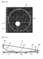
FIG. 7 shows the cross-section of theduct 16. Theduct 16 has a hollow structure which is manufactured in such a way thatrods 16a are respectively provided in a leading edge and a tailing edge of theduct 16 and boards are adhered to each other inside and outside based on therods 16a. Therefore, the boards which form theduct 16 can be more easily adhered to each other using therods 16a. - In this case, the inside surface of the
duct 16 includes, in positional sequence from the leading edge to the tailing edge, an inclinedcurved portion 16b, a horizontallinear portion 16c and an inclinedlinear portion 16d which are integrated with each other. The horizontallinear portion 16c is connected to the outer ends of the blades of thepre-swirl stator 14. Here, because the horizontallinear portion 16c is parallel to the center axis X of thescrew 12, the coupling of theduct 16 to thepre-swirl stator 14 can be facilitated. - Furthermore, horizontal lengths L1, L2 and L3 (on the extension line of the horizontal linear portion) of the inclined
curved portion 16b, the horizontallinear portion 16c and the inclinedlinear portion 16d respectively are 0.4 times, 0.2 times and 0.4 times the chord length of theduct 16. - Here, with respect to the extension line of the horizontal
linear portion 16c, an inclined angle α defined by the inclinedcurved portion 16b on the inner surface of the leading edge of theduct 16 is set such that it ranges from 20° to 30°, and an inclined angle β defined by the inclinedlinear portion 16d on the inner surface of the tailing edge of theduct 16 is set such that it ranges from 2° to 6°. - Hence, due to the inclined angle α of the inclined
curved portion 16b on the leading edge of theduct 16, the inclinedcurved portion 16b can smoothly guide fluid into theduct 16 and thus reduce the pressure of fluid around the inlet of theduct 16, thus increasing the current speed of the fluid. In addition, due to the inclined angle β of the inclinedlinear portion 16d, the inclinedlinear portion 16d guides fluid such that fluid can flow into thescrew 12 after it is increased in current speed around the outlet of theduct 16. Therefore, theduct 16 can function to accelerate and rectify the flow of fluid, thus reducing propeller-induced hull-pressure fluctuations. - Meanwhile, as shown in
FIG. 2A , a distance H between the end of the tailing edge of theduct 16 and the center line of the blades of thescrew 12 is set such that the minimum gap between theduct 16 and thescrew 12 which can prevent theduct 16 from interfering with the blades of thescrew 12 can be ensured and the distance H is not greater than 0.3 times the diameter Dp of thescrew 12. Preferably, the minimum of the distance H is greater than or equal to 0.1 times the diameter Dp of thescrew 12. Furthermore, the maximum of the distance H is less than or equal to 0.3 times the diameter Dp of thescrew 12. The reason for the setting of the maximum of the distance H is to prevent the fluid flow from accelerating and to prevent the rectifying effect of theduct 16 from becoming worse. - Hereinafter, the operation and effect of the ducted pre-swirl stator assembly according to the present invention will be explained.
- As stated above, the
pre-swirl stator 14 having the blades is provided on the circumferential outer surface of thestern boss 10 disposed at the stern side of the hull. Theduct 16 is installed such that the center axis Y thereof is disposed at a position eccentric upwards and rightwards from the center axis X of thescrew 12 and the outer ends of the blades of thepre-swirl stator 14 are coupled to the inner surface of theduct 16. Furthermore, theduct 16 is reliably fastened to the hull and thestern boss 10 by thesupport 18. Theduct 16 changes an inflow angle at which fluid is drawn from thepre-swirl stator 14 into thescrew 12, thus reducing a loss of kinetic energy of fluid, and increasing the axial kinetic energy of the fluid, thereby markedly enhancing the propulsion performance of thescrew 12. - Here, the reason for the structure in which the center axis Y of the
duct 16 is eccentric upwards and rightwards from the center axis Y of thescrew 12 is that cavitation mainly occurs on thescrew 12 in an 11 to 3 o'clock section based on the center axis X of thescrew 12 in the direction indicated from the stern side towards the bow side. In other words, due to the eccentric structure of theduct 16 according to the present invention, the current speed of fluid can be increased in the above-mentioned 11 to 3 o'clock section of thescrew 12, thus reducing cavitation. - This fact can be more clearly understood by the graph of
FIG. 8 which compares the distributions of counter currents in the case where only thepre-swirl stator 14 is provided on thestern boss 10 and the case where both thepre-swirl stator 14 and theduct 16 which is eccentric upwards and rightwards are installed. Here, the upward eccentricity Hc and the rightward eccentricity Bc of the center axis Y of theduct 16 with respect to the center axis X of thescrew 12 are set in the manner described above. - In detail,
FIG. 8 illustrates the case (expressed in red) where only thepre-swirl stator 14 is provided and the case (expressed in blue) where both thepre-swirl stator 14 and theduct 16 which is eccentric upwards and rightwards are installed. Referring toFIG. 8 , with regard to the velocity distributions Vx of axial counter current of thescrew 12 in a 50% portion and a 70% portion of the radius of the blade, it is to be interpreted that the case of the structure having both thepre-swirl stator 14 and theduct 16 which is eccentric upwards and rightwards is increased in the axial velocity into ascrew 12 by about 15% compared to the case where only thepre-swirl stator 14 is provided. - Furthermore, as shown in
FIG. 9 , when comparing the volume of cavitation formed in the case where only thepre-swirl stator 14 is installed and that of the case where both thepre-swirl stator 14 and theduct 16 are installed, the case of the ducted pre-swirl stator reduces the volume of formed cavitation by 60%, because theduct 16 surrounds the outer ends of the blades of thepre-swirl stator 14 and thus conducts the fluid flow accelerating and rectifying function. Here, since theduct 16 is firmly fastened to the hull and thestern boss 10 by thesupport 18, the structural stability of theduct 16 can be further enhanced. - As a result, propeller-induced hull-pressure fluctuations can be reduced to 50%. Thereby, the present invention can markedly reduce hull-pressure fluctuations transmitted to the hull by generation of cavitation, thus improving the vibration performances of the hull. Furthermore, this can be more clearly interpreted by the graph of
FIG. 10 which comparatively shows the effect on thrust and fluctuating pressure in the case where neitherpre-swirl stator 14 nor theduct 16 are installed, the case where only thepre-swirl stator 14 is installed and the case where both thepre-swirl stator 14 and theduct 16 are installed. That is, the recovery of energy loss of thepre-swirl stator 14 with respect to the rotational direction, and an additional thrust generating effect of the duct and an inflow current acceleration effect of the duct increase the thrust of thescrew 12. In addition, theduct 16 functions to reduce fluctuating pressure in thescrew 12. - Furthermore,
FIGS 11 and12 compare velocity distributions Vx of axial counter currents in thescrew 12 in the case where the center axis Y of theduct 16 is eccentrically displaced only upwards from the center axis X of thescrew 12 and the case where the center axis Y of theduct 16 is eccentrically displaced rightwards and upwards from the center axis X of thescrew 12. - In detail, in the case of the
typical screw 12 that rotates in the clockwise direction based on the direction indicated from the stern side of the hull, cavitations are mainly generated in a section between -10 ° and 50° of the entire rotational area of thescrew 12, that is, in an 11 to 3 o'clock section based on the center axis X of thescrew 12 in the direction indicated from the stern side towards the bow side. Therefore, to increase the axial velocity of fluid drawn into thescrew 12 in this section, the center axis Y of theduct 16 is set such that it is eccentric upwards and rightwards from the center axis X of thescrew 12. - Thereby, the axial velocity of fluid drawn into the
screw 12 can be increased in the section between -10° and 50° of the entire rotational area of thescrew 12, thus reducing the generation of cavitations. As a result, fluctuating pressure applied to the hull by cavitations generated in thescrew 12 can be markedly reduced. - In other words, the effects of improving the velocity distribution of fluid drawn into the
screw 12 in such a way as to eccentrically displace the center axis Y of theduct 16 upwards and rightwards from the center axis X of thescrew 12 can be appreciated by analyzing the velocity distributions Vx of axial counter currents in thescrew 12 for the case ofFIG. 11 where the center axis Y of theduct 16 is eccentrically displaced only upwards from the center axis X of thescrew 12 and the case ofFIG. 12 where the center axis Y of theduct 16 is eccentrically displaced rightwards and upwards from the center axis X of thescrew 12. - First,
FIG. 11 is a graph comparing the velocity distribution Vx of axial counter current for the case where the center axis Y of theduct 16 is eccentrically displaced upwards from the center axis X of thescrew 12 to that of the case where the center axis Y is aligned with the center axis X. It is clear that the axial velocity of fluid for the case of the upward eccentric axis structure is increased around a section corresponding to 0° of the entire rotational area of thescrew 12 compared to that of the aligned axis structure. On the other hand, it is clear that the axial velocity of fluid of the case of the upward eccentric axis structure is reduced around a section corresponding to 50° of the entire rotational area of thescrew 12 compared to that of the aligned axis structure. -
FIG. 12 is a graph comparing the velocity distribution Vx of axial counter current to the case where the center axis Y of theduct 16 is eccentrically displaced rightwards and upwards from the center axis X of thescrew 12 to that of the case where it is eccentrically displaced only upwards therefrom. It can be understood that the axial velocity of fluid for the case of the upward and rightward eccentric axis structure is increased around a section corresponding to 50° of the entire rotational area of thescrew 12 compared to that of the upward eccentric axis structure. - In conclusion, it can be appreciated that in the case of the present invention where the center axis Y of the
duct 16 is eccentrically displaced rightwards and upwards from the center axis X of thescrew 12, the axial velocity of fluid drawn into thescrew 12 is increased compared to that of the case where the center axis Y is aligned with the center axis X or eccentrically displaced only upwards therefrom. As such, an increase in the axial velocity of fluid drawn into thescrew 12 reduces the generation of cavitations and mitigates fluctuating pressure applied to the hull. In particular, in the present invention, an increase in the axial velocity of fluid drawn into thescrew 12 is focused on a section of the entire rotational area of thescrew 12 in which cavitations are mainly generated, thus maximizing the above-mentioned effects of the present invention. - Furthermore, referring to in
FIG. 7 showing the cross-section of theduct 16, the inclinedcurved portion 16b which is formed in the leading edge of theduct 16 at the inclined angle α can guide the smooth inflow of fluid into theduct 16, thus promoting an increase in current speed of the fluid. This can be interpreted by the views ofFIG. 13 comparing variations of the current speed of fluid between the present invention and the conventional technique. In detail, as shown in profiles of variations of the current speed of fluid which are formed around the ducts, theduct 16 of the present invention increases the current speed of the fluid by 5% compared to that of the conventional technique. The increase in current speed fluid exhibits the fluid flow accelerating and rectifying effect of theduct 16, thus restraining generation of cavitations in thescrew 12, thereby mitigating propeller-induced hull-pressure fluctuations. - In addition, referring to
FIG. 14 illustrating the rectification effect depending on the distance H between the end of the tailing edge of theduct 16 and the center axis X of thescrew 12, it is appreciated that the rectification effect is maximized when the distance H is less 0.3 times the diameter Dp of thescrew 12. In detail, when the distance H is greater than or equal to 0.3 times the diameter Dp of thescrew 12, the velocity distribution Vx is rapidly reduced compared to that of the case of 0.2 times. This proves the deterioration of propulsion performance and the effect of reducing the fluctuating pressure. Therefore, in the present invention, the distance H between the end of the tailing edge of theduct 16 and the center axis X of thescrew 12 is set at a range between the minimum distance at which interference between thescrew 12 andduct 16 does not occur and the maximum distance at which the deterioration of current speed is not induced. - As described above, in a ducted pre-swirl stator assembly according to the present invention, a pre-swirl stator is provided ahead of a screw of a ship to vary an angle at which fluid is drawn into the screw when the ship is in motion, thus enhancing the propulsion performance. A duct is disposed ahead of the screw to accelerate and rectify the flow of fluid drawn into the screw such that the propulsion performance can be further enhanced. To realize the optimum coupling between the duct and the pre-swirl stator, the duct is coupled to the pre-swirl stator such that the center axis of the duct is eccentric from the center axis of the screw. Thereby, the propulsion performance of the screw can be maximized.
- Furthermore, due to realization of the optimal arrangement between the pre-swirl stator and the duct, the present invention can reduce the volume of cavitations generated in the screw, thus mitigating fluctuating pressure of the screw applied to the hull of the ship, thereby minimizing the vibrations of the ship.
- Although the preferred embodiment of the present invention has been disclosed for illustrative purposes, those skilled in the art will appreciate that various modifications, additions and substitutions are possible, without departing from the scope and spirit of the invention as disclosed in the accompanying claims.
Claims (8)
- A ducted pre-swirl stator assembly, comprising:a pre-swirl stator provided on a stern boss of a hull, the pre-swirl stator having at least one blade extending in a radial direction based on a center axis of a screw;a cylindrical duct coupled to an outer end of the blade of the pre-swirl stator; anda support fastening the duct to the hull,wherein a center axis of the duct is eccentric upwards and rightwards from the center axis of the screw with respect to a direction indicated from a stern side to a bow side.
- The ducted pre-swirl stator assembly as set forth in claim 1, wherein an eccentricity of the center axis of the duct from the center axis of the screw is set with respect to a diameter Dp of the screw such that an upward eccentricity (Hc) satisfies 0 < Hc < 0.3Dp and a rightward eccentricity (Bc) satisfies 0 < Bc < 0.2Dp.
- The ducted pre-swirl stator assembly as set forth in claim 2, wherein an inner diameter (Dd) of the duct satisfies 0.5Dp ≤ Dd ≤ 1.0Dp with respect to the diameter (Dp) of the screw.
- The ducted pre-swirl stator assembly as set forth in claim 1 or 2, wherein the duct has:an inclined curved portion on an inner surface of a leading edge of the duct, the inclined curved portion being inclined at an inclined angle ranging from 20° to 30°;an inclined linear portion on an inner surface of a tailing edge of the duct, the inclined linear portion being inclined at an inclined angle ranging from 2 ° to 6 °; anda horizontal linear portion formed between the inclined curved portion and the inclined linear portion, the horizontal linear portion being connected to the outer end of the blade of the pre-swirl stator,wherein the inclined angle of each of the inclined curved portion and the inclined linear portion is set with respect to a line extending from the horizontal linear portion in a direction parallel to the horizontal linear portion.
- The ducted pre-swirl stator assembly as set forth in claim 4, wherein lengths of the inclined curved portion, the horizontal linear portion and the inclined linear portion respectively are 0.4 times, 0.2 times and 0.4 times a chord length of the duct.
- The ducted pre-swirl stator assembly as set forth in claim 1 or 2, wherein a distance between an end of a tailing edge of the duct and a center line of blades of the screw in a longitudinal direction of the hull is set with respect to the diameter Dp of the screw such that 0.1Dp < H < 0.3Dp is satisfied.
- The ducted pre-swirl stator assembly as set forth in claim 1 or 2, wherein the support comprises:an upper support member connecting an outer surface of the duct to a lower portion of the hull; andan upper support member connecting an inner surface of the duct to a lower portion of the stern boss.
- The ducted pre-swirl stator assembly as set forth in claim 1 or 2, wherein the blade of the pre-swirl stator comprises a plurality of blades arranged such that based on the center axis of the screw, two blades are disposed on a port side and one blade is disposed on a starboard side, or two blades are disposed on the port side and two blades are disposed on the starboard side, wherein at least one pair of blades of the port/starboard side blades of the pre-swirl stator is level with the center axis of the screw, and a remaining blade or remaining blades of the pre-swirl stator are inclined upwards with respect to the center axis of the screw.
Applications Claiming Priority (1)
| Application Number | Priority Date | Filing Date | Title |
|---|---|---|---|
| KR1020090087978A KR101023052B1 (en) | 2009-09-17 | 2009-09-17 | Current fixed wing with duct |
Publications (2)
| Publication Number | Publication Date |
|---|---|
| EP2298640A1 true EP2298640A1 (en) | 2011-03-23 |
| EP2298640B1 EP2298640B1 (en) | 2012-05-23 |
Family
ID=42983873
Family Applications (1)
| Application Number | Title | Priority Date | Filing Date |
|---|---|---|---|
| EP10164448A Revoked EP2298640B1 (en) | 2009-09-17 | 2010-05-31 | Ducted pre-swirl stator assembly |
Country Status (6)
| Country | Link |
|---|---|
| EP (1) | EP2298640B1 (en) |
| JP (1) | JP5539025B2 (en) |
| KR (1) | KR101023052B1 (en) |
| CN (1) | CN102020011B (en) |
| DK (1) | DK2298640T3 (en) |
| ES (1) | ES2387872T3 (en) |
Cited By (1)
| Publication number | Priority date | Publication date | Assignee | Title |
|---|---|---|---|---|
| CN121469785A (en) * | 2026-01-09 | 2026-02-06 | 大连船舶重工集团有限公司 | An energy-saving guide wheel top support device with pre-swirl guiding function |
Families Citing this family (15)
| Publication number | Priority date | Publication date | Assignee | Title |
|---|---|---|---|---|
| ES2502475T3 (en) * | 2011-11-11 | 2014-10-03 | Becker Marine Systems Gmbh & Co. Kg | Device for reducing the demand for propulsion power of a vessel |
| KR101402484B1 (en) * | 2012-05-15 | 2014-06-11 | 현대중공업 주식회사 | A propulsion apparatus for ship |
| KR101985450B1 (en) * | 2012-11-01 | 2019-06-03 | 대우조선해양 주식회사 | Duct Supporting Structure of Vessel and Vessel Having the same |
| DE202013101943U1 (en) | 2013-05-06 | 2013-06-11 | Becker Marine Systems Gmbh & Co. Kg | Device for reducing the power requirement of a watercraft |
| CN103332280B (en) * | 2013-07-01 | 2017-09-29 | 中国船舶科学研究中心上海分部 | Radiance type preposed guide wheel |
| KR101864355B1 (en) * | 2014-06-30 | 2018-06-04 | 현대중공업 주식회사 | Ship propulsion unit that rectifier unit is applied |
| KR101857851B1 (en) * | 2015-12-29 | 2018-05-14 | 류재원 | a ship propeller efficiency improving device with a symmetric cotrollable angle |
| KR101764400B1 (en) * | 2016-11-24 | 2017-08-10 | 재단법인한국조선해양기자재연구원 | Duct apparatus for ship with twist type stator |
| KR102032054B1 (en) * | 2018-04-30 | 2019-10-14 | 류재원 | a ship propeller efficiency improving device with a symmetric cotrollable angle |
| CN109606596B (en) * | 2018-11-29 | 2025-05-06 | 中国船舶科学研究中心(中国船舶重工集团公司第七0二研究所) | Energy-saving semi-guide wheel in front of propeller |
| EP4021798A4 (en) * | 2019-08-28 | 2023-10-25 | Chairman, Defence Research and Development Organisation (DRDO) | A marine propeller |
| CN112027017B (en) * | 2020-08-17 | 2022-09-27 | 西北工业大学 | Internal and external double-channel passive propeller and design method |
| CN111976937B (en) * | 2020-09-01 | 2022-09-16 | 上海船舶运输科学研究所 | Sweepback wing type propulsion efficiency improving device |
| CN113212718A (en) * | 2021-04-13 | 2021-08-06 | 上海外高桥造船有限公司 | Energy-saving stator for ship |
| CN113212717A (en) * | 2021-04-13 | 2021-08-06 | 上海外高桥造船有限公司 | Distortion type energy-saving stator for ship |
Citations (5)
| Publication number | Priority date | Publication date | Assignee | Title |
|---|---|---|---|---|
| JPS57158191A (en) * | 1981-03-26 | 1982-09-29 | Mitsubishi Heavy Ind Ltd | Fin type device for improving propelling performance |
| JPS58139395U (en) * | 1982-03-16 | 1983-09-19 | 三菱重工業株式会社 | Reaction Fin |
| EP0470339A1 (en) * | 1990-08-10 | 1992-02-12 | Herbert Prof. Dr.-Ing. Schneekluth | Deflector fins system |
| JP2008239060A (en) * | 2007-03-28 | 2008-10-09 | Mitsui Eng & Shipbuild Co Ltd | Stern horizontal duct and ship |
| US20090084301A1 (en) * | 2007-03-10 | 2009-04-02 | Friedrich Mewis | Device for reducing the drive power requirement of a ship |
Family Cites Families (12)
| Publication number | Priority date | Publication date | Assignee | Title |
|---|---|---|---|---|
| JPS537096A (en) * | 1976-07-06 | 1978-01-23 | Mitsui Eng & Shipbuild Co Ltd | Ship |
| JPS5387490A (en) * | 1977-10-06 | 1978-08-01 | Mitsui Eng & Shipbuild Co Ltd | Ship |
| JPS5853624B2 (en) * | 1978-08-10 | 1983-11-30 | 三井造船株式会社 | How to attach a ring-shaped structure to the stern of the hull |
| DE3216578C1 (en) * | 1982-05-04 | 1983-10-13 | Herbert Prof. Dr.-Ing. 5100 Aachen Schneekluth | Flow control surface at the stern of screw-in ships |
| US4801280A (en) * | 1984-01-03 | 1989-01-31 | Johannes Schuit | Stator for marine propeller |
| JPS6455197U (en) * | 1987-10-01 | 1989-04-05 | ||
| DE4223570C1 (en) * | 1992-07-17 | 1993-09-16 | Herbert Prof. Dr.-Ing. 5100 Aachen De Schneekluth | Streamline control for variable pitch marine screw - has ring duct with smaller diameter than screw to reduce flow rate around hub and increase flow rate through propeller blades |
| JP3235772B2 (en) | 1995-12-22 | 2001-12-04 | 住友重機械工業株式会社 | Ship with stern duct |
| JP2006306304A (en) * | 2005-04-28 | 2006-11-09 | Niigata Shipbuilding & Repair Inc | Propulsion device and its manufacturing method |
| JP4684778B2 (en) * | 2005-06-15 | 2011-05-18 | エムエイチアイマリンエンジニアリング株式会社 | Small ship propulsion performance improvement device |
| JP5025247B2 (en) * | 2006-12-13 | 2012-09-12 | ユニバーサル造船株式会社 | Ship duct and ship with ship duct |
| KR100908297B1 (en) | 2007-09-10 | 2009-07-21 | 강충묵 | Duct type propeller unit of marine propulsion system |
-
2009
- 2009-09-17 KR KR1020090087978A patent/KR101023052B1/en active Active
-
2010
- 2010-05-28 JP JP2010122281A patent/JP5539025B2/en not_active Expired - Fee Related
- 2010-05-31 CN CN201010196606.9A patent/CN102020011B/en not_active Expired - Fee Related
- 2010-05-31 DK DK10164448.2T patent/DK2298640T3/en active
- 2010-05-31 ES ES10164448T patent/ES2387872T3/en active Active
- 2010-05-31 EP EP10164448A patent/EP2298640B1/en not_active Revoked
Patent Citations (5)
| Publication number | Priority date | Publication date | Assignee | Title |
|---|---|---|---|---|
| JPS57158191A (en) * | 1981-03-26 | 1982-09-29 | Mitsubishi Heavy Ind Ltd | Fin type device for improving propelling performance |
| JPS58139395U (en) * | 1982-03-16 | 1983-09-19 | 三菱重工業株式会社 | Reaction Fin |
| EP0470339A1 (en) * | 1990-08-10 | 1992-02-12 | Herbert Prof. Dr.-Ing. Schneekluth | Deflector fins system |
| US20090084301A1 (en) * | 2007-03-10 | 2009-04-02 | Friedrich Mewis | Device for reducing the drive power requirement of a ship |
| JP2008239060A (en) * | 2007-03-28 | 2008-10-09 | Mitsui Eng & Shipbuild Co Ltd | Stern horizontal duct and ship |
Cited By (1)
| Publication number | Priority date | Publication date | Assignee | Title |
|---|---|---|---|---|
| CN121469785A (en) * | 2026-01-09 | 2026-02-06 | 大连船舶重工集团有限公司 | An energy-saving guide wheel top support device with pre-swirl guiding function |
Also Published As
| Publication number | Publication date |
|---|---|
| CN102020011A (en) | 2011-04-20 |
| JP5539025B2 (en) | 2014-07-02 |
| CN102020011B (en) | 2016-01-20 |
| KR20110030048A (en) | 2011-03-23 |
| JP2011063258A (en) | 2011-03-31 |
| EP2298640B1 (en) | 2012-05-23 |
| DK2298640T3 (en) | 2012-06-25 |
| KR101023052B1 (en) | 2011-03-24 |
| ES2387872T3 (en) | 2012-10-03 |
Similar Documents
| Publication | Publication Date | Title |
|---|---|---|
| EP2298640B1 (en) | Ducted pre-swirl stator assembly | |
| US11448232B2 (en) | Propeller blade | |
| KR101534284B1 (en) | Apparatus for Improving Thrust of Ship | |
| JP5230852B1 (en) | Small ducted propeller and ship | |
| US6352408B1 (en) | Slip inhibiting boat propeller | |
| EP2096320B1 (en) | Cascade of axial compressor | |
| US10544798B2 (en) | Flow guiding device for a fan | |
| KR20120058632A (en) | Fixing of current-carrying wings and ducts with ducts | |
| KR20110083998A (en) | Marine Duct | |
| US20070025845A1 (en) | Axial turbine | |
| KR20120023843A (en) | Duct fixing method of pre-swirl stator | |
| WO2021033419A1 (en) | Vane wheel for wind power generation and wind power generation system | |
| KR101313183B1 (en) | Propeller boss cap and Propulsion apparatus having the same | |
| KR20120030124A (en) | Method for manufacuring ducted pre-swirl stator | |
| KR101764400B1 (en) | Duct apparatus for ship with twist type stator | |
| KR101757471B1 (en) | Propeller hub | |
| KR101506050B1 (en) | Duct Structure for Ship | |
| KR101674548B1 (en) | Variable guide vane for axial flow pump or mixed flow pump including | |
| KR20260024709A (en) | Noise reduction aircraft propeller | |
| KR20160002232A (en) | Ship propulsion unit that rectifier unit is applied | |
| KR20200000046A (en) | Propulsion apparatus | |
| KR102117384B1 (en) | Supporting structure of duct for ship | |
| US7080977B2 (en) | Discharge diffuser for screw compressor | |
| KR20230094685A (en) | Pre-swirl stator having coanda effect | |
| CN121568873A (en) | Device for reducing the propulsion power requirement of a watercraft |
Legal Events
| Date | Code | Title | Description |
|---|---|---|---|
| PUAI | Public reference made under article 153(3) epc to a published international application that has entered the european phase |
Free format text: ORIGINAL CODE: 0009012 |
|
| AK | Designated contracting states |
Kind code of ref document: A1 Designated state(s): AL AT BE BG CH CY CZ DE DK EE ES FI FR GB GR HR HU IE IS IT LI LT LU LV MC MK MT NL NO PL PT RO SE SI SK SM TR |
|
| AX | Request for extension of the european patent |
Extension state: BA ME RS |
|
| 17P | Request for examination filed |
Effective date: 20110922 |
|
| GRAP | Despatch of communication of intention to grant a patent |
Free format text: ORIGINAL CODE: EPIDOSNIGR1 |
|
| RIC1 | Information provided on ipc code assigned before grant |
Ipc: B63H 5/16 20060101AFI20111031BHEP |
|
| GRAS | Grant fee paid |
Free format text: ORIGINAL CODE: EPIDOSNIGR3 |
|
| GRAA | (expected) grant |
Free format text: ORIGINAL CODE: 0009210 |
|
| AK | Designated contracting states |
Kind code of ref document: B1 Designated state(s): AL AT BE BG CH CY CZ DE DK EE ES FI FR GB GR HR HU IE IS IT LI LT LU LV MC MK MT NL NO PL PT RO SE SI SK SM TR |
|
| REG | Reference to a national code |
Ref country code: GB Ref legal event code: FG4D |
|
| REG | Reference to a national code |
Ref country code: CH Ref legal event code: EP |
|
| REG | Reference to a national code |
Ref country code: AT Ref legal event code: REF Ref document number: 558955 Country of ref document: AT Kind code of ref document: T Effective date: 20120615 |
|
| REG | Reference to a national code |
Ref country code: RO Ref legal event code: EPE |
|
| REG | Reference to a national code |
Ref country code: IE Ref legal event code: FG4D |
|
| REG | Reference to a national code |
Ref country code: DK Ref legal event code: T3 |
|
| REG | Reference to a national code |
Ref country code: DE Ref legal event code: R096 Ref document number: 602010001624 Country of ref document: DE Effective date: 20120802 |
|
| REG | Reference to a national code |
Ref country code: GR Ref legal event code: EP Ref document number: 20120401348 Country of ref document: GR Effective date: 20120713 |
|
| REG | Reference to a national code |
Ref country code: NL Ref legal event code: VDEP Effective date: 20120523 |
|
| REG | Reference to a national code |
Ref country code: ES Ref legal event code: FG2A Ref document number: 2387872 Country of ref document: ES Kind code of ref document: T3 Effective date: 20121003 |
|
| REG | Reference to a national code |
Ref country code: LT Ref legal event code: MG4D Effective date: 20120523 |
|
| PG25 | Lapsed in a contracting state [announced via postgrant information from national office to epo] |
Ref country code: NO Free format text: LAPSE BECAUSE OF FAILURE TO SUBMIT A TRANSLATION OF THE DESCRIPTION OR TO PAY THE FEE WITHIN THE PRESCRIBED TIME-LIMIT Effective date: 20120823 Ref country code: CY Free format text: LAPSE BECAUSE OF FAILURE TO SUBMIT A TRANSLATION OF THE DESCRIPTION OR TO PAY THE FEE WITHIN THE PRESCRIBED TIME-LIMIT Effective date: 20120523 Ref country code: LT Free format text: LAPSE BECAUSE OF FAILURE TO SUBMIT A TRANSLATION OF THE DESCRIPTION OR TO PAY THE FEE WITHIN THE PRESCRIBED TIME-LIMIT Effective date: 20120523 Ref country code: IS Free format text: LAPSE BECAUSE OF FAILURE TO SUBMIT A TRANSLATION OF THE DESCRIPTION OR TO PAY THE FEE WITHIN THE PRESCRIBED TIME-LIMIT Effective date: 20120923 Ref country code: SE Free format text: LAPSE BECAUSE OF FAILURE TO SUBMIT A TRANSLATION OF THE DESCRIPTION OR TO PAY THE FEE WITHIN THE PRESCRIBED TIME-LIMIT Effective date: 20120523 |
|
| REG | Reference to a national code |
Ref country code: AT Ref legal event code: MK05 Ref document number: 558955 Country of ref document: AT Kind code of ref document: T Effective date: 20120523 |
|
| PG25 | Lapsed in a contracting state [announced via postgrant information from national office to epo] |
Ref country code: LV Free format text: LAPSE BECAUSE OF FAILURE TO SUBMIT A TRANSLATION OF THE DESCRIPTION OR TO PAY THE FEE WITHIN THE PRESCRIBED TIME-LIMIT Effective date: 20120523 Ref country code: PT Free format text: LAPSE BECAUSE OF FAILURE TO SUBMIT A TRANSLATION OF THE DESCRIPTION OR TO PAY THE FEE WITHIN THE PRESCRIBED TIME-LIMIT Effective date: 20120924 Ref country code: SI Free format text: LAPSE BECAUSE OF FAILURE TO SUBMIT A TRANSLATION OF THE DESCRIPTION OR TO PAY THE FEE WITHIN THE PRESCRIBED TIME-LIMIT Effective date: 20120523 Ref country code: HR Free format text: LAPSE BECAUSE OF FAILURE TO SUBMIT A TRANSLATION OF THE DESCRIPTION OR TO PAY THE FEE WITHIN THE PRESCRIBED TIME-LIMIT Effective date: 20120523 |
|
| PG25 | Lapsed in a contracting state [announced via postgrant information from national office to epo] |
Ref country code: MC Free format text: LAPSE BECAUSE OF NON-PAYMENT OF DUE FEES Effective date: 20120531 Ref country code: BE Free format text: LAPSE BECAUSE OF FAILURE TO SUBMIT A TRANSLATION OF THE DESCRIPTION OR TO PAY THE FEE WITHIN THE PRESCRIBED TIME-LIMIT Effective date: 20120523 |
|
| PG25 | Lapsed in a contracting state [announced via postgrant information from national office to epo] |
Ref country code: SK Free format text: LAPSE BECAUSE OF FAILURE TO SUBMIT A TRANSLATION OF THE DESCRIPTION OR TO PAY THE FEE WITHIN THE PRESCRIBED TIME-LIMIT Effective date: 20120523 Ref country code: NL Free format text: LAPSE BECAUSE OF FAILURE TO SUBMIT A TRANSLATION OF THE DESCRIPTION OR TO PAY THE FEE WITHIN THE PRESCRIBED TIME-LIMIT Effective date: 20120523 Ref country code: EE Free format text: LAPSE BECAUSE OF FAILURE TO SUBMIT A TRANSLATION OF THE DESCRIPTION OR TO PAY THE FEE WITHIN THE PRESCRIBED TIME-LIMIT Effective date: 20120523 Ref country code: CZ Free format text: LAPSE BECAUSE OF FAILURE TO SUBMIT A TRANSLATION OF THE DESCRIPTION OR TO PAY THE FEE WITHIN THE PRESCRIBED TIME-LIMIT Effective date: 20120523 Ref country code: AT Free format text: LAPSE BECAUSE OF FAILURE TO SUBMIT A TRANSLATION OF THE DESCRIPTION OR TO PAY THE FEE WITHIN THE PRESCRIBED TIME-LIMIT Effective date: 20120523 |
|
| REG | Reference to a national code |
Ref country code: IE Ref legal event code: MM4A |
|
| PG25 | Lapsed in a contracting state [announced via postgrant information from national office to epo] |
Ref country code: PL Free format text: LAPSE BECAUSE OF FAILURE TO SUBMIT A TRANSLATION OF THE DESCRIPTION OR TO PAY THE FEE WITHIN THE PRESCRIBED TIME-LIMIT Effective date: 20120523 Ref country code: IT Free format text: LAPSE BECAUSE OF FAILURE TO SUBMIT A TRANSLATION OF THE DESCRIPTION OR TO PAY THE FEE WITHIN THE PRESCRIBED TIME-LIMIT Effective date: 20120523 Ref country code: MK Free format text: LAPSE BECAUSE OF FAILURE TO SUBMIT A TRANSLATION OF THE DESCRIPTION OR TO PAY THE FEE WITHIN THE PRESCRIBED TIME-LIMIT Effective date: 20120523 |
|
| PLBI | Opposition filed |
Free format text: ORIGINAL CODE: 0009260 |
|
| 26 | Opposition filed |
Opponent name: BECKER MARINE SYSTEMS GMBH & CO. KG Effective date: 20130221 |
|
| PLAX | Notice of opposition and request to file observation + time limit sent |
Free format text: ORIGINAL CODE: EPIDOSNOBS2 |
|
| PG25 | Lapsed in a contracting state [announced via postgrant information from national office to epo] |
Ref country code: IE Free format text: LAPSE BECAUSE OF NON-PAYMENT OF DUE FEES Effective date: 20120531 |
|
| REG | Reference to a national code |
Ref country code: DE Ref legal event code: R026 Ref document number: 602010001624 Country of ref document: DE Effective date: 20130221 |
|
| PG25 | Lapsed in a contracting state [announced via postgrant information from national office to epo] |
Ref country code: BG Free format text: LAPSE BECAUSE OF FAILURE TO SUBMIT A TRANSLATION OF THE DESCRIPTION OR TO PAY THE FEE WITHIN THE PRESCRIBED TIME-LIMIT Effective date: 20120823 Ref country code: MT Free format text: LAPSE BECAUSE OF FAILURE TO SUBMIT A TRANSLATION OF THE DESCRIPTION OR TO PAY THE FEE WITHIN THE PRESCRIBED TIME-LIMIT Effective date: 20120523 |
|
| PLBB | Reply of patent proprietor to notice(s) of opposition received |
Free format text: ORIGINAL CODE: EPIDOSNOBS3 |
|
| PG25 | Lapsed in a contracting state [announced via postgrant information from national office to epo] |
Ref country code: AL Free format text: LAPSE BECAUSE OF FAILURE TO SUBMIT A TRANSLATION OF THE DESCRIPTION OR TO PAY THE FEE WITHIN THE PRESCRIBED TIME-LIMIT Effective date: 20120523 |
|
| PG25 | Lapsed in a contracting state [announced via postgrant information from national office to epo] |
Ref country code: TR Free format text: LAPSE BECAUSE OF FAILURE TO SUBMIT A TRANSLATION OF THE DESCRIPTION OR TO PAY THE FEE WITHIN THE PRESCRIBED TIME-LIMIT Effective date: 20120523 |
|
| PG25 | Lapsed in a contracting state [announced via postgrant information from national office to epo] |
Ref country code: SM Free format text: LAPSE BECAUSE OF FAILURE TO SUBMIT A TRANSLATION OF THE DESCRIPTION OR TO PAY THE FEE WITHIN THE PRESCRIBED TIME-LIMIT Effective date: 20120523 Ref country code: LU Free format text: LAPSE BECAUSE OF NON-PAYMENT OF DUE FEES Effective date: 20120531 |
|
| PG25 | Lapsed in a contracting state [announced via postgrant information from national office to epo] |
Ref country code: HU Free format text: LAPSE BECAUSE OF FAILURE TO SUBMIT A TRANSLATION OF THE DESCRIPTION OR TO PAY THE FEE WITHIN THE PRESCRIBED TIME-LIMIT Effective date: 20100531 |
|
| REG | Reference to a national code |
Ref country code: CH Ref legal event code: PL |
|
| PG25 | Lapsed in a contracting state [announced via postgrant information from national office to epo] |
Ref country code: CH Free format text: LAPSE BECAUSE OF NON-PAYMENT OF DUE FEES Effective date: 20140531 Ref country code: LI Free format text: LAPSE BECAUSE OF NON-PAYMENT OF DUE FEES Effective date: 20140531 |
|
| APBM | Appeal reference recorded |
Free format text: ORIGINAL CODE: EPIDOSNREFNO |
|
| APBP | Date of receipt of notice of appeal recorded |
Free format text: ORIGINAL CODE: EPIDOSNNOA2O |
|
| APAH | Appeal reference modified |
Free format text: ORIGINAL CODE: EPIDOSCREFNO |
|
| APBQ | Date of receipt of statement of grounds of appeal recorded |
Free format text: ORIGINAL CODE: EPIDOSNNOA3O |
|
| REG | Reference to a national code |
Ref country code: FR Ref legal event code: PLFP Year of fee payment: 7 |
|
| REG | Reference to a national code |
Ref country code: DE Ref legal event code: R064 Ref document number: 602010001624 Country of ref document: DE Ref country code: DE Ref legal event code: R103 Ref document number: 602010001624 Country of ref document: DE |
|
| APBU | Appeal procedure closed |
Free format text: ORIGINAL CODE: EPIDOSNNOA9O |
|
| REG | Reference to a national code |
Ref country code: FR Ref legal event code: PLFP Year of fee payment: 8 |
|
| PGFP | Annual fee paid to national office [announced via postgrant information from national office to epo] |
Ref country code: DE Payment date: 20170530 Year of fee payment: 8 Ref country code: GB Payment date: 20170524 Year of fee payment: 8 Ref country code: FR Payment date: 20170522 Year of fee payment: 8 Ref country code: RO Payment date: 20170529 Year of fee payment: 8 Ref country code: DK Payment date: 20170524 Year of fee payment: 8 |
|
| RDAF | Communication despatched that patent is revoked |
Free format text: ORIGINAL CODE: EPIDOSNREV1 |
|
| RDAG | Patent revoked |
Free format text: ORIGINAL CODE: 0009271 |
|
| STAA | Information on the status of an ep patent application or granted ep patent |
Free format text: STATUS: PATENT REVOKED |
|
| PGFP | Annual fee paid to national office [announced via postgrant information from national office to epo] |
Ref country code: ES Payment date: 20170601 Year of fee payment: 8 Ref country code: FI Payment date: 20170519 Year of fee payment: 8 |
|
| 27W | Patent revoked |
Effective date: 20170517 |
|
| GBPR | Gb: patent revoked under art. 102 of the ep convention designating the uk as contracting state |
Effective date: 20170517 |
|
| POAG | Date of filing of petition for review recorded |
Free format text: ORIGINAL CODE: EPIDOSNPRV3 |
|
| POAH | Number of petition for review recorded |
Free format text: ORIGINAL CODE: EPIDOSNPRV1 |
|
| POAI | Petitioner in petition for review recorded |
Free format text: ORIGINAL CODE: EPIDOSNPRV2 |
|
| PGFP | Annual fee paid to national office [announced via postgrant information from national office to epo] |
Ref country code: GR Payment date: 20180530 Year of fee payment: 9 |
|
| POAK | Decision taken: petition for review obviously unsubstantiated |
Free format text: ORIGINAL CODE: 0009255 |
|
| PRVN | Petition for review not allowed |
Free format text: PETITION FOR REVIEW OBVIOUSLY UNSUBSTANTIATED Effective date: 20190613 |