EP2298591A1 - A fixing system for a sulky in small work machines - Google Patents
A fixing system for a sulky in small work machines Download PDFInfo
- Publication number
- EP2298591A1 EP2298591A1 EP10175771A EP10175771A EP2298591A1 EP 2298591 A1 EP2298591 A1 EP 2298591A1 EP 10175771 A EP10175771 A EP 10175771A EP 10175771 A EP10175771 A EP 10175771A EP 2298591 A1 EP2298591 A1 EP 2298591A1
- Authority
- EP
- European Patent Office
- Prior art keywords
- sulky
- frame
- machine
- seat
- chassis
- Prior art date
- Legal status (The legal status is an assumption and is not a legal conclusion. Google has not performed a legal analysis and makes no representation as to the accuracy of the status listed.)
- Granted
Links
- 230000001747 exhibiting effect Effects 0.000 description 2
- 238000003466 welding Methods 0.000 description 2
- 229910000831 Steel Inorganic materials 0.000 description 1
- 230000005540 biological transmission Effects 0.000 description 1
- 230000000903 blocking effect Effects 0.000 description 1
- 230000000295 complement effect Effects 0.000 description 1
- 230000001419 dependent effect Effects 0.000 description 1
- 230000005489 elastic deformation Effects 0.000 description 1
- 239000000463 material Substances 0.000 description 1
- 230000007246 mechanism Effects 0.000 description 1
- 239000002184 metal Substances 0.000 description 1
- 238000000034 method Methods 0.000 description 1
- 239000010959 steel Substances 0.000 description 1
- 229920002994 synthetic fiber Polymers 0.000 description 1
Images


Classifications
-
- B—PERFORMING OPERATIONS; TRANSPORTING
- B60—VEHICLES IN GENERAL
- B60N—SEATS SPECIALLY ADAPTED FOR VEHICLES; VEHICLE PASSENGER ACCOMMODATION NOT OTHERWISE PROVIDED FOR
- B60N2/00—Seats specially adapted for vehicles; Arrangement or mounting of seats in vehicles
- B60N2/005—Arrangement or mounting of seats in vehicles, e.g. dismountable auxiliary seats
- B60N2/015—Attaching seats directly to vehicle chassis
- B60N2/01508—Attaching seats directly to vehicle chassis using quick release attachments
-
- B—PERFORMING OPERATIONS; TRANSPORTING
- B60—VEHICLES IN GENERAL
- B60N—SEATS SPECIALLY ADAPTED FOR VEHICLES; VEHICLE PASSENGER ACCOMMODATION NOT OTHERWISE PROVIDED FOR
- B60N2/00—Seats specially adapted for vehicles; Arrangement or mounting of seats in vehicles
- B60N2/50—Seat suspension devices
- B60N2/502—Seat suspension devices attached to the base of the seat
-
- B—PERFORMING OPERATIONS; TRANSPORTING
- B60—VEHICLES IN GENERAL
- B60N—SEATS SPECIALLY ADAPTED FOR VEHICLES; VEHICLE PASSENGER ACCOMMODATION NOT OTHERWISE PROVIDED FOR
- B60N2/00—Seats specially adapted for vehicles; Arrangement or mounting of seats in vehicles
- B60N2/50—Seat suspension devices
- B60N2/54—Seat suspension devices using mechanical springs
- B60N2/546—Leaf- or flexion springs
Abstract
Description
- The invention relates to small self-propelling work machines equipped with a sulky for the operator.
- These small machines, for example lawnmowers, walking tractors and the like, exhibit a frame which supports a motor and respective, generally hydraulic, transmission devices.
- The frame is equipped with drive wheels and guiding equipment.
- Work tools are applied to the frame, and they are generally positioned on the frame using appropriate hinge supports.
- A sulky is also fitted onto the frame in a position such that the pedals and the operating levers are within the operator's reach.
- The sulky comprises a seat connected to an unsuspended base which is destined to be fitted to the frame of the machine by elastic springing means.
- Generally, the unsuspended part of the sulky is rigidly constrained to the frame of the machine by means of bolts, the frame and the unsuspended part of the sulky being appropriately perforated for the purpose in pre-established positions.
- The perforation requires the use of appropriate templates.
- The prior art comprises a number of drawbacks, including the complicated structure of the sulky, suspended using spring mechanisms, and the complicated system for fitting it to the frame, besides the time that it takes to fit and remove the sulky whenever access to the parts of the machine which are positioned under the sulky is necessary.
- In the prior art these operations are very laborious and require time and equipment in order for them to be carried out correctly.
- Further drawbacks in the prior art are that the machine underneath the sulky is generally covered by a shield which must also be removed in order for access to the parts of the machine underneath the sulky to be gained.
- Also the applying and removing of the shield are long and laborious operations and require previous removal of the sulky.
- The problem is to realize a sulky that has a simplified shape, and that can be quickly fitted to and removed from the frame of the machine while guaranteeing at the same time a stable and secure fastening to the frame, which might also be integrated with the shield in such a way as to be removable and fittable back together with the shield.
- The aim of the invention is to make available a frame-sulky unit which offers a simple, reliable and economical solution to this problem.
- A further aim of the invention is to make available a frame-sulky unit to which a shield can be stably associated.
- The aims are attained by the invention with the assembly described in the independent claim.
- The dependent claims recite particular and/or alternative solutions aimed at improving the results of the invention.
- In particular, the sulky of the invention comprises a seat removably fitted to the frame of the machine, by means of devices which are vertically elastically deformable under the weight bearing down on the seat.
- The elastically-deformable devices are made of a fashioned and elastically-flexible chassis, the function of which is to fasten the seat directly to the frame of the machine.
- The chassis has a horizontal portion, which is parallel to the above longitudinal members of the machine, and a bent portion which is inclined such as to connect to the longitudinal members, the flat end of the chassis being connected to the frame of the machine above the longitudinal members.
- The chassis is preferably U-shaped and exhibits a flat part near the base of the U, while the ends of each wing constitute the bent part and are connected to the respective longitudinal member by interposing a sliding cursor on the longitudinal member in relation to which the wings can perform small rotations.
- In particular, the cursor shows an opening facing upwards into which the lower end of the chassis can be freely inserted.
- The opening can be inclined either towards the front or the back of the frame of the machine.
- Finally, the chassis can constitute a support for a shield, which is stably connected to it.
- The advantages and constructional and functional characteristics of the invention will emerge from the detailed description that follows, illustrated in the figures of the accompanying tables of drawings and relating to a preferred embodiment of the invention, given by way of non-limiting example.
-
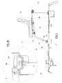
Figure 1 illustrates the invention in a perspective view; -
figure 2 shows the invention in plan view; -
figure 3 shows section III-III offigure 2 ; -
figure 3A is an enlarged detail offigure 3 . - The figures illustrate the
frame 1 of a small self-propelling machine, onto which a sulky 2 has been fitted. - In the invention the
sulky 2 comprises aseat 21 which is rigidly fitted onto achassis 3. - The
chassis 3 is constituted by a U-shapedtube exhibiting wings 33 which are in turn bent downwards. - In particular the
chassis 3 comprises twoparallel crossbars crossbars 31 is front-mounted to theseat 21, while theother crossbar 32 functions as a support for the rear part of the seat. - Then ends of the
wings 33 are joined by atubular crossbar 34 which is fitted to them by means of welding or by other convenient means. - A
cursor 11 is inserted on eachlongitudinal member 10 of theframe 1 , whichcursor 11 friction-slides and is provided with an opening 12 inclined upwards with respect to the longitudinal member. - The mouthpiece of the opening 12 narrows slightly.
- The
openings 12 are suitable for snap-fitting thetubular crossbar 34. - A
bush 35 made of slightly-deformable synthetic material is positioned between the ends of thecrossbar 34 and therespective opening 12. - A
body 134 made of fashioned sheet-metal having a downwardly-tapered truncoconical shape and exhibiting acentral hole 37 is fixed, preferably by means of welding, to the centre of thebase 36 of the chassis 3 (figure 3A ). Theframe 1 comprises a rectangular vertical portion 13 (figure 1 ), which is provided with acrossbar 15 functioning as a support for thebase 36 of thechassis 3. - A body 14 (
figure 3A ) having a complementary shape to thebody 134 such as snugly to receive thebody 134 is fixed centred to thecrossbar 15 by known means. - The
body 14 also exhibits a central hole aligned to the hole in thebody 134 and abolt 5 blocks the twobodies - The sulky is fitted simply by snap-fitting the ends of the
crossbar 34 into theopenings 12 of thecursors 11, and then by blocking the twobodies - Removal is done by performing the same operations in reverse order and it is often unnecessary to pull out the
crossbars 34 from theopenings 12. - The
chassis 3 further comprisesbrackets 37, and others not shown, to which a shield, also not illustrated, can be stably fitted, in the shape of a cap which completely covers the chassis and extends to cover the rear part of the frame of the machine. - In this way, by removing or lifting the
chassis 3 the shield is contextually also removed or lifted. - Thanks to its shape and to the methods for fitting it onto the
frame 1 of the machine, theframe 3 is subjected to vertical elastic movements, due to the elastic deformations of the frame made possible by the moving of thecursors 11 on thelongitudinal members 10 of the frame of the machine. - With this aim, the
chassis 3 must be made of suitable material, for example steel, and sized in a way such that it can elastically deform under the weight of the operator sitting on theseat 21. - The invention is not limited to the example described herein, and variants and improvements thereto can be applied without its forsaking the ambit of the following claims.
Claims (11)
- A sulky (2) for small work machines comprising a seat (21) and means for removably fixing the seat (21) to a frame (1) of the machine, wherein the means for removably fixing the seat (21) are vertically elastically deformable under a weight bearing down on the seat, characterised in that the elastically deformable means comprise a U-shaped chassis (3) having wings (33) bent forward and_downwards to connect to longitudinal members (10) of the frame (1) in cursors (11) that friction-slide on the longitudinal members (10).
- The sulky of claim 1, characterised in that the U-shaped chassis (3), has a base (36) which is rigidly constrained to the frame (1) of the machine in a position that is vertically distant from the longitudinal members (10).
- The sulky of claim 1, characterised in that in the connection of the ends of each wing (33) to respective longitudinal members (10) an end of the respective wing (33) can perform small rotations.
- The sulky of claim 3, characterised in that the ends of the two wings (33) are connected by a crossbar (34), ends of which are engaged in the respective cursor (11).
- The sulky of claim 4, characterised in that each cursor comprises an opening (12) inclined upwards and destined to receive the crossbar (34) in a snap-fit.
- The sulky of claim 5, characterised in that the opening (12) is inclined towards a rear of the frame (1) of the machine.
- The sulky of claim 5, characterised in that the opening (12) is inclined towards a front of the frame of the machine.
- The sulky of claim 1, characterised in that centring means are located at a centre of the base of the chassis (3), which centring means are destined to couple with centring means constrained to the machine frame (1) above the longitudinal members (10), the centring means constrained to the machine frame comprising reciprocal fastening means.
- The sulky of claim 1 characterised in that crossbars (31,32) for supporting the seat (2) are positioned between the wings (33) of the chassis (3), in a portion of the chassis (3) which is parallel to the longitudinal members (10) of the machine.
- The sulky of claim 1 characterised in that the seat (2) can rotate in relation to an axis of one of the crossbars (31,32).
- The sulky of claim 2 characterised in that a shield is stably constrained to the elastically-deformable chassis (3).
Applications Claiming Priority (1)
| Application Number | Priority Date | Filing Date | Title |
|---|---|---|---|
| ITRE2009A000091A IT1396257B1 (en) | 2009-09-22 | 2009-09-22 | SITTING SEAT SYSTEM IN SMALL WORKING MACHINES. |
Publications (2)
| Publication Number | Publication Date |
|---|---|
| EP2298591A1 true EP2298591A1 (en) | 2011-03-23 |
| EP2298591B1 EP2298591B1 (en) | 2012-03-14 |
Family
ID=41571094
Family Applications (1)
| Application Number | Title | Priority Date | Filing Date |
|---|---|---|---|
| EP10175771A Active EP2298591B1 (en) | 2009-09-22 | 2010-09-08 | A fixing system for a sulky in small work machines |
Country Status (3)
| Country | Link |
|---|---|
| EP (1) | EP2298591B1 (en) |
| AT (1) | ATE549201T1 (en) |
| IT (1) | IT1396257B1 (en) |
Families Citing this family (1)
| Publication number | Priority date | Publication date | Assignee | Title |
|---|---|---|---|---|
| CA3158652A1 (en) | 2021-05-14 | 2022-11-14 | Techtronic Cordless Gp | Removable seat and lawnmowers with removable seats |
Citations (8)
| Publication number | Priority date | Publication date | Assignee | Title |
|---|---|---|---|---|
| GB190919836A (en) * | 1909-08-30 | 1910-02-10 | Arthur Wilshire | An Improved Adjustable Seat for Sulkies and like Vehicles. |
| US2533573A (en) * | 1947-08-19 | 1950-12-12 | Gabel Charles | Tractor seat having spring mounting |
| US2676032A (en) * | 1950-02-23 | 1954-04-20 | Locke Steel Chain Co | Sulky hitch |
| US2880034A (en) * | 1955-02-14 | 1959-03-31 | Simplicity Mfg Company | Garden sulky with dump body |
| EP0518158A1 (en) * | 1991-06-14 | 1992-12-16 | Deere & Company | Seat shifting for a vehicle seat |
| US5876085A (en) * | 1997-02-27 | 1999-03-02 | Milsco Manufacturing Company | Adjustable vehicle seat |
| US6135412A (en) * | 1999-05-12 | 2000-10-24 | Buehler; Richard B. | Universal seat assembly for garden tractor |
| US20090184448A1 (en) * | 2008-01-22 | 2009-07-23 | Hiser Nicholas R | Isolation system for a seat or the like, and vehicle incorporating same |
-
2009
- 2009-09-22 IT ITRE2009A000091A patent/IT1396257B1/en active
-
2010
- 2010-09-08 EP EP10175771A patent/EP2298591B1/en active Active
- 2010-09-08 AT AT10175771T patent/ATE549201T1/en active
Patent Citations (8)
| Publication number | Priority date | Publication date | Assignee | Title |
|---|---|---|---|---|
| GB190919836A (en) * | 1909-08-30 | 1910-02-10 | Arthur Wilshire | An Improved Adjustable Seat for Sulkies and like Vehicles. |
| US2533573A (en) * | 1947-08-19 | 1950-12-12 | Gabel Charles | Tractor seat having spring mounting |
| US2676032A (en) * | 1950-02-23 | 1954-04-20 | Locke Steel Chain Co | Sulky hitch |
| US2880034A (en) * | 1955-02-14 | 1959-03-31 | Simplicity Mfg Company | Garden sulky with dump body |
| EP0518158A1 (en) * | 1991-06-14 | 1992-12-16 | Deere & Company | Seat shifting for a vehicle seat |
| US5876085A (en) * | 1997-02-27 | 1999-03-02 | Milsco Manufacturing Company | Adjustable vehicle seat |
| US6135412A (en) * | 1999-05-12 | 2000-10-24 | Buehler; Richard B. | Universal seat assembly for garden tractor |
| US20090184448A1 (en) * | 2008-01-22 | 2009-07-23 | Hiser Nicholas R | Isolation system for a seat or the like, and vehicle incorporating same |
Also Published As
| Publication number | Publication date |
|---|---|
| ITRE20090091A1 (en) | 2011-03-23 |
| IT1396257B1 (en) | 2012-11-16 |
| ATE549201T1 (en) | 2012-03-15 |
| EP2298591B1 (en) | 2012-03-14 |
Similar Documents
| Publication | Publication Date | Title |
|---|---|---|
| US5779272A (en) | Roll-over protection system | |
| AU2013232536B2 (en) | Handhold assembly | |
| PL208746B1 (en) | Tracked vehicle featuring variable wheel track | |
| EP1476344B1 (en) | Pallet truck | |
| EP2298591B1 (en) | A fixing system for a sulky in small work machines | |
| EP2138386B1 (en) | Holding device for a manoeuvring device | |
| KR20140093370A (en) | The Side Hinge Structural Body For Mounting Rear Sheet In A Car | |
| EP2340699A1 (en) | Linkage attachment means for a vehicle | |
| EP1481616A1 (en) | Baby seat | |
| DE20315461U1 (en) | child seat | |
| CN216805706U (en) | Scooter with adjustable front and rear positions of faucet | |
| DE102005046125B4 (en) | Foldable tricycle chassis | |
| RU189480U1 (en) | HOLDER SPARE WHEEL VEHICLE | |
| EP2634041B1 (en) | Vehicle seat and commercial motor vehicle with a vehicle seat | |
| CN216508714U (en) | Assembly trolley locking mechanism and assembly trolley | |
| CN216512733U (en) | Assembly dolly prevents foreign matter gyro wheel and assembly dolly | |
| CN216508715U (en) | Assembly trolley workpiece support and assembly trolley | |
| DE102009001696A1 (en) | Golf trolley for golf bag i.e. stretcher-standbag, has automatic stand mechanism folded in rolling mode when trolley is bent in pulling direction and supporting trolley in standing mode when trolley is bent in sliding direction | |
| AU2018200961A1 (en) | Apparatus for Removal and Fitting of a Panel of a Vehicle and Associated Method of Use | |
| CN216508717U (en) | Assembly dolly hangs mechanism and assembly dolly | |
| DE102012103102A1 (en) | Waste container has pallet which is provided on upper edge of container wall to hold waste bag, and cover that is arranged on pallet and is moved relative to pallet | |
| DE20114926U1 (en) | Suspension for a child's bicycle seat | |
| EP2308701B1 (en) | Axle suspension system for a vehicle rear axle and additional axle | |
| DE2817948C2 (en) | Removable air screen, grille or the like. | |
| JPH0132529Y2 (en) |
Legal Events
| Date | Code | Title | Description |
|---|---|---|---|
| PUAI | Public reference made under article 153(3) epc to a published international application that has entered the european phase |
Free format text: ORIGINAL CODE: 0009012 |
|
| AK | Designated contracting states |
Kind code of ref document: A1 Designated state(s): AL AT BE BG CH CY CZ DE DK EE ES FI FR GB GR HR HU IE IS IT LI LT LU LV MC MK MT NL NO PL PT RO SE SI SK SM TR |
|
| AX | Request for extension of the european patent |
Extension state: BA ME RS |
|
| 17P | Request for examination filed |
Effective date: 20110802 |
|
| RIC1 | Information provided on ipc code assigned before grant |
Ipc: B60N 2/50 20060101ALI20110824BHEP Ipc: B60N 2/015 20060101AFI20110824BHEP Ipc: B60N 2/54 20060101ALI20110824BHEP |
|
| GRAP | Despatch of communication of intention to grant a patent |
Free format text: ORIGINAL CODE: EPIDOSNIGR1 |
|
| GRAS | Grant fee paid |
Free format text: ORIGINAL CODE: EPIDOSNIGR3 |
|
| GRAA | (expected) grant |
Free format text: ORIGINAL CODE: 0009210 |
|
| AK | Designated contracting states |
Kind code of ref document: B1 Designated state(s): AL AT BE BG CH CY CZ DE DK EE ES FI FR GB GR HR HU IE IS IT LI LT LU LV MC MK MT NL NO PL PT RO SE SI SK SM TR |
|
| REG | Reference to a national code |
Ref country code: GB Ref legal event code: FG4D |
|
| REG | Reference to a national code |
Ref country code: AT Ref legal event code: REF Ref document number: 549201 Country of ref document: AT Kind code of ref document: T Effective date: 20120315 Ref country code: CH Ref legal event code: EP |
|
| REG | Reference to a national code |
Ref country code: IE Ref legal event code: FG4D |
|
| REG | Reference to a national code |
Ref country code: DE Ref legal event code: R096 Ref document number: 602010001045 Country of ref document: DE Effective date: 20120510 |
|
| REG | Reference to a national code |
Ref country code: NL Ref legal event code: VDEP Effective date: 20120314 |
|
| PG25 | Lapsed in a contracting state [announced via postgrant information from national office to epo] |
Ref country code: HR Free format text: LAPSE BECAUSE OF FAILURE TO SUBMIT A TRANSLATION OF THE DESCRIPTION OR TO PAY THE FEE WITHIN THE PRESCRIBED TIME-LIMIT Effective date: 20120314 Ref country code: NO Free format text: LAPSE BECAUSE OF FAILURE TO SUBMIT A TRANSLATION OF THE DESCRIPTION OR TO PAY THE FEE WITHIN THE PRESCRIBED TIME-LIMIT Effective date: 20120614 Ref country code: LT Free format text: LAPSE BECAUSE OF FAILURE TO SUBMIT A TRANSLATION OF THE DESCRIPTION OR TO PAY THE FEE WITHIN THE PRESCRIBED TIME-LIMIT Effective date: 20120314 |
|
| LTIE | Lt: invalidation of european patent or patent extension |
Effective date: 20120314 |
|
| PG25 | Lapsed in a contracting state [announced via postgrant information from national office to epo] |
Ref country code: LV Free format text: LAPSE BECAUSE OF FAILURE TO SUBMIT A TRANSLATION OF THE DESCRIPTION OR TO PAY THE FEE WITHIN THE PRESCRIBED TIME-LIMIT Effective date: 20120314 Ref country code: FI Free format text: LAPSE BECAUSE OF FAILURE TO SUBMIT A TRANSLATION OF THE DESCRIPTION OR TO PAY THE FEE WITHIN THE PRESCRIBED TIME-LIMIT Effective date: 20120314 Ref country code: GR Free format text: LAPSE BECAUSE OF FAILURE TO SUBMIT A TRANSLATION OF THE DESCRIPTION OR TO PAY THE FEE WITHIN THE PRESCRIBED TIME-LIMIT Effective date: 20120615 |
|
| REG | Reference to a national code |
Ref country code: AT Ref legal event code: MK05 Ref document number: 549201 Country of ref document: AT Kind code of ref document: T Effective date: 20120314 |
|
| PG25 | Lapsed in a contracting state [announced via postgrant information from national office to epo] |
Ref country code: CY Free format text: LAPSE BECAUSE OF FAILURE TO SUBMIT A TRANSLATION OF THE DESCRIPTION OR TO PAY THE FEE WITHIN THE PRESCRIBED TIME-LIMIT Effective date: 20120314 |
|
| PG25 | Lapsed in a contracting state [announced via postgrant information from national office to epo] |
Ref country code: CZ Free format text: LAPSE BECAUSE OF FAILURE TO SUBMIT A TRANSLATION OF THE DESCRIPTION OR TO PAY THE FEE WITHIN THE PRESCRIBED TIME-LIMIT Effective date: 20120314 Ref country code: EE Free format text: LAPSE BECAUSE OF FAILURE TO SUBMIT A TRANSLATION OF THE DESCRIPTION OR TO PAY THE FEE WITHIN THE PRESCRIBED TIME-LIMIT Effective date: 20120314 Ref country code: RO Free format text: LAPSE BECAUSE OF FAILURE TO SUBMIT A TRANSLATION OF THE DESCRIPTION OR TO PAY THE FEE WITHIN THE PRESCRIBED TIME-LIMIT Effective date: 20120314 Ref country code: SE Free format text: LAPSE BECAUSE OF FAILURE TO SUBMIT A TRANSLATION OF THE DESCRIPTION OR TO PAY THE FEE WITHIN THE PRESCRIBED TIME-LIMIT Effective date: 20120314 Ref country code: SI Free format text: LAPSE BECAUSE OF FAILURE TO SUBMIT A TRANSLATION OF THE DESCRIPTION OR TO PAY THE FEE WITHIN THE PRESCRIBED TIME-LIMIT Effective date: 20120314 Ref country code: PL Free format text: LAPSE BECAUSE OF FAILURE TO SUBMIT A TRANSLATION OF THE DESCRIPTION OR TO PAY THE FEE WITHIN THE PRESCRIBED TIME-LIMIT Effective date: 20120314 Ref country code: BE Free format text: LAPSE BECAUSE OF FAILURE TO SUBMIT A TRANSLATION OF THE DESCRIPTION OR TO PAY THE FEE WITHIN THE PRESCRIBED TIME-LIMIT Effective date: 20120314 Ref country code: IS Free format text: LAPSE BECAUSE OF FAILURE TO SUBMIT A TRANSLATION OF THE DESCRIPTION OR TO PAY THE FEE WITHIN THE PRESCRIBED TIME-LIMIT Effective date: 20120714 |
|
| PG25 | Lapsed in a contracting state [announced via postgrant information from national office to epo] |
Ref country code: PT Free format text: LAPSE BECAUSE OF FAILURE TO SUBMIT A TRANSLATION OF THE DESCRIPTION OR TO PAY THE FEE WITHIN THE PRESCRIBED TIME-LIMIT Effective date: 20120716 Ref country code: SK Free format text: LAPSE BECAUSE OF FAILURE TO SUBMIT A TRANSLATION OF THE DESCRIPTION OR TO PAY THE FEE WITHIN THE PRESCRIBED TIME-LIMIT Effective date: 20120314 |
|
| PLBE | No opposition filed within time limit |
Free format text: ORIGINAL CODE: 0009261 |
|
| STAA | Information on the status of an ep patent application or granted ep patent |
Free format text: STATUS: NO OPPOSITION FILED WITHIN TIME LIMIT |
|
| PG25 | Lapsed in a contracting state [announced via postgrant information from national office to epo] |
Ref country code: DK Free format text: LAPSE BECAUSE OF FAILURE TO SUBMIT A TRANSLATION OF THE DESCRIPTION OR TO PAY THE FEE WITHIN THE PRESCRIBED TIME-LIMIT Effective date: 20120314 Ref country code: AT Free format text: LAPSE BECAUSE OF FAILURE TO SUBMIT A TRANSLATION OF THE DESCRIPTION OR TO PAY THE FEE WITHIN THE PRESCRIBED TIME-LIMIT Effective date: 20120314 Ref country code: NL Free format text: LAPSE BECAUSE OF FAILURE TO SUBMIT A TRANSLATION OF THE DESCRIPTION OR TO PAY THE FEE WITHIN THE PRESCRIBED TIME-LIMIT Effective date: 20120314 |
|
| 26N | No opposition filed |
Effective date: 20121217 |
|
| REG | Reference to a national code |
Ref country code: DE Ref legal event code: R097 Ref document number: 602010001045 Country of ref document: DE Effective date: 20121217 |
|
| PG25 | Lapsed in a contracting state [announced via postgrant information from national office to epo] |
Ref country code: MC Free format text: LAPSE BECAUSE OF NON-PAYMENT OF DUE FEES Effective date: 20120930 Ref country code: ES Free format text: LAPSE BECAUSE OF FAILURE TO SUBMIT A TRANSLATION OF THE DESCRIPTION OR TO PAY THE FEE WITHIN THE PRESCRIBED TIME-LIMIT Effective date: 20120625 |
|
| REG | Reference to a national code |
Ref country code: IE Ref legal event code: MM4A |
|
| PG25 | Lapsed in a contracting state [announced via postgrant information from national office to epo] |
Ref country code: BG Free format text: LAPSE BECAUSE OF FAILURE TO SUBMIT A TRANSLATION OF THE DESCRIPTION OR TO PAY THE FEE WITHIN THE PRESCRIBED TIME-LIMIT Effective date: 20120614 Ref country code: IE Free format text: LAPSE BECAUSE OF NON-PAYMENT OF DUE FEES Effective date: 20120908 |
|
| PG25 | Lapsed in a contracting state [announced via postgrant information from national office to epo] |
Ref country code: MT Free format text: LAPSE BECAUSE OF FAILURE TO SUBMIT A TRANSLATION OF THE DESCRIPTION OR TO PAY THE FEE WITHIN THE PRESCRIBED TIME-LIMIT Effective date: 20120314 Ref country code: AL Free format text: LAPSE BECAUSE OF FAILURE TO SUBMIT A TRANSLATION OF THE DESCRIPTION OR TO PAY THE FEE WITHIN THE PRESCRIBED TIME-LIMIT Effective date: 20120314 |
|
| PG25 | Lapsed in a contracting state [announced via postgrant information from national office to epo] |
Ref country code: TR Free format text: LAPSE BECAUSE OF FAILURE TO SUBMIT A TRANSLATION OF THE DESCRIPTION OR TO PAY THE FEE WITHIN THE PRESCRIBED TIME-LIMIT Effective date: 20120314 |
|
| PG25 | Lapsed in a contracting state [announced via postgrant information from national office to epo] |
Ref country code: SM Free format text: LAPSE BECAUSE OF FAILURE TO SUBMIT A TRANSLATION OF THE DESCRIPTION OR TO PAY THE FEE WITHIN THE PRESCRIBED TIME-LIMIT Effective date: 20120314 Ref country code: LU Free format text: LAPSE BECAUSE OF NON-PAYMENT OF DUE FEES Effective date: 20120908 |
|
| PG25 | Lapsed in a contracting state [announced via postgrant information from national office to epo] |
Ref country code: HU Free format text: LAPSE BECAUSE OF FAILURE TO SUBMIT A TRANSLATION OF THE DESCRIPTION OR TO PAY THE FEE WITHIN THE PRESCRIBED TIME-LIMIT Effective date: 20100908 |
|
| REG | Reference to a national code |
Ref country code: CH Ref legal event code: PL |
|
| GBPC | Gb: european patent ceased through non-payment of renewal fee |
Effective date: 20140908 |
|
| PG25 | Lapsed in a contracting state [announced via postgrant information from national office to epo] |
Ref country code: MK Free format text: LAPSE BECAUSE OF FAILURE TO SUBMIT A TRANSLATION OF THE DESCRIPTION OR TO PAY THE FEE WITHIN THE PRESCRIBED TIME-LIMIT Effective date: 20120314 Ref country code: CH Free format text: LAPSE BECAUSE OF NON-PAYMENT OF DUE FEES Effective date: 20140930 Ref country code: LI Free format text: LAPSE BECAUSE OF NON-PAYMENT OF DUE FEES Effective date: 20140930 Ref country code: GB Free format text: LAPSE BECAUSE OF NON-PAYMENT OF DUE FEES Effective date: 20140908 |
|
| REG | Reference to a national code |
Ref country code: FR Ref legal event code: PLFP Year of fee payment: 7 |
|
| REG | Reference to a national code |
Ref country code: FR Ref legal event code: PLFP Year of fee payment: 8 |
|
| REG | Reference to a national code |
Ref country code: FR Ref legal event code: PLFP Year of fee payment: 9 |
|
| P01 | Opt-out of the competence of the unified patent court (upc) registered |
Effective date: 20230605 |
|
| PGFP | Annual fee paid to national office [announced via postgrant information from national office to epo] |
Ref country code: IT Payment date: 20230628 Year of fee payment: 14 |
|
| PGFP | Annual fee paid to national office [announced via postgrant information from national office to epo] |
Ref country code: FR Payment date: 20230925 Year of fee payment: 14 Ref country code: DE Payment date: 20230927 Year of fee payment: 14 |