EP2297960B1 - Method for receiving data streams and corresponding method for transmission - Google Patents
Method for receiving data streams and corresponding method for transmission Download PDFInfo
- Publication number
- EP2297960B1 EP2297960B1 EP09772405.8A EP09772405A EP2297960B1 EP 2297960 B1 EP2297960 B1 EP 2297960B1 EP 09772405 A EP09772405 A EP 09772405A EP 2297960 B1 EP2297960 B1 EP 2297960B1
- Authority
- EP
- European Patent Office
- Prior art keywords
- receiver
- error correction
- data stream
- stream
- mode
- Prior art date
- Legal status (The legal status is an assumption and is not a legal conclusion. Google has not performed a legal analysis and makes no representation as to the accuracy of the status listed.)
- Active
Links
- 238000000034 method Methods 0.000 title claims description 35
- 230000005540 biological transmission Effects 0.000 title claims description 23
- 238000012937 correction Methods 0.000 claims description 118
- 230000008859 change Effects 0.000 claims description 47
- 230000015654 memory Effects 0.000 claims description 25
- 230000006870 function Effects 0.000 claims description 9
- 230000008054 signal transmission Effects 0.000 claims 1
- 230000004913 activation Effects 0.000 description 44
- 230000008901 benefit Effects 0.000 description 10
- 238000004422 calculation algorithm Methods 0.000 description 6
- 238000010586 diagram Methods 0.000 description 3
- 239000003795 chemical substances by application Substances 0.000 description 2
- 238000005259 measurement Methods 0.000 description 2
- 238000009877 rendering Methods 0.000 description 2
- 238000012360 testing method Methods 0.000 description 2
- 238000004891 communication Methods 0.000 description 1
- 230000009849 deactivation Effects 0.000 description 1
- 230000000694 effects Effects 0.000 description 1
- 238000005538 encapsulation Methods 0.000 description 1
- 238000005516 engineering process Methods 0.000 description 1
- 230000006872 improvement Effects 0.000 description 1
- 230000010354 integration Effects 0.000 description 1
- 238000012544 monitoring process Methods 0.000 description 1
- 239000013307 optical fiber Substances 0.000 description 1
- 230000008569 process Effects 0.000 description 1
- 238000012545 processing Methods 0.000 description 1
- 238000011084 recovery Methods 0.000 description 1
- 230000009467 reduction Effects 0.000 description 1
- 238000000926 separation method Methods 0.000 description 1
Images


Classifications
-
- H—ELECTRICITY
- H04—ELECTRIC COMMUNICATION TECHNIQUE
- H04N—PICTORIAL COMMUNICATION, e.g. TELEVISION
- H04N21/00—Selective content distribution, e.g. interactive television or video on demand [VOD]
- H04N21/20—Servers specifically adapted for the distribution of content, e.g. VOD servers; Operations thereof
- H04N21/23—Processing of content or additional data; Elementary server operations; Server middleware
- H04N21/238—Interfacing the downstream path of the transmission network, e.g. adapting the transmission rate of a video stream to network bandwidth; Processing of multiplex streams
- H04N21/2383—Channel coding or modulation of digital bit-stream, e.g. QPSK modulation
-
- H—ELECTRICITY
- H04—ELECTRIC COMMUNICATION TECHNIQUE
- H04N—PICTORIAL COMMUNICATION, e.g. TELEVISION
- H04N19/00—Methods or arrangements for coding, decoding, compressing or decompressing digital video signals
- H04N19/10—Methods or arrangements for coding, decoding, compressing or decompressing digital video signals using adaptive coding
- H04N19/102—Methods or arrangements for coding, decoding, compressing or decompressing digital video signals using adaptive coding characterised by the element, parameter or selection affected or controlled by the adaptive coding
-
- H—ELECTRICITY
- H04—ELECTRIC COMMUNICATION TECHNIQUE
- H04N—PICTORIAL COMMUNICATION, e.g. TELEVISION
- H04N19/00—Methods or arrangements for coding, decoding, compressing or decompressing digital video signals
- H04N19/10—Methods or arrangements for coding, decoding, compressing or decompressing digital video signals using adaptive coding
- H04N19/134—Methods or arrangements for coding, decoding, compressing or decompressing digital video signals using adaptive coding characterised by the element, parameter or criterion affecting or controlling the adaptive coding
- H04N19/154—Measured or subjectively estimated visual quality after decoding, e.g. measurement of distortion
-
- H—ELECTRICITY
- H04—ELECTRIC COMMUNICATION TECHNIQUE
- H04N—PICTORIAL COMMUNICATION, e.g. TELEVISION
- H04N19/00—Methods or arrangements for coding, decoding, compressing or decompressing digital video signals
- H04N19/10—Methods or arrangements for coding, decoding, compressing or decompressing digital video signals using adaptive coding
- H04N19/134—Methods or arrangements for coding, decoding, compressing or decompressing digital video signals using adaptive coding characterised by the element, parameter or criterion affecting or controlling the adaptive coding
- H04N19/164—Feedback from the receiver or from the transmission channel
- H04N19/166—Feedback from the receiver or from the transmission channel concerning the amount of transmission errors, e.g. bit error rate [BER]
-
- H—ELECTRICITY
- H04—ELECTRIC COMMUNICATION TECHNIQUE
- H04N—PICTORIAL COMMUNICATION, e.g. TELEVISION
- H04N19/00—Methods or arrangements for coding, decoding, compressing or decompressing digital video signals
- H04N19/10—Methods or arrangements for coding, decoding, compressing or decompressing digital video signals using adaptive coding
- H04N19/169—Methods or arrangements for coding, decoding, compressing or decompressing digital video signals using adaptive coding characterised by the coding unit, i.e. the structural portion or semantic portion of the video signal being the object or the subject of the adaptive coding
- H04N19/188—Methods or arrangements for coding, decoding, compressing or decompressing digital video signals using adaptive coding characterised by the coding unit, i.e. the structural portion or semantic portion of the video signal being the object or the subject of the adaptive coding the unit being a video data packet, e.g. a network abstraction layer [NAL] unit
-
- H—ELECTRICITY
- H04—ELECTRIC COMMUNICATION TECHNIQUE
- H04N—PICTORIAL COMMUNICATION, e.g. TELEVISION
- H04N19/00—Methods or arrangements for coding, decoding, compressing or decompressing digital video signals
- H04N19/65—Methods or arrangements for coding, decoding, compressing or decompressing digital video signals using error resilience
- H04N19/67—Methods or arrangements for coding, decoding, compressing or decompressing digital video signals using error resilience involving unequal error protection [UEP], i.e. providing protection according to the importance of the data
-
- H—ELECTRICITY
- H04—ELECTRIC COMMUNICATION TECHNIQUE
- H04N—PICTORIAL COMMUNICATION, e.g. TELEVISION
- H04N21/00—Selective content distribution, e.g. interactive television or video on demand [VOD]
- H04N21/20—Servers specifically adapted for the distribution of content, e.g. VOD servers; Operations thereof
- H04N21/23—Processing of content or additional data; Elementary server operations; Server middleware
- H04N21/238—Interfacing the downstream path of the transmission network, e.g. adapting the transmission rate of a video stream to network bandwidth; Processing of multiplex streams
- H04N21/2389—Multiplex stream processing, e.g. multiplex stream encrypting
-
- H—ELECTRICITY
- H04—ELECTRIC COMMUNICATION TECHNIQUE
- H04N—PICTORIAL COMMUNICATION, e.g. TELEVISION
- H04N21/00—Selective content distribution, e.g. interactive television or video on demand [VOD]
- H04N21/40—Client devices specifically adapted for the reception of or interaction with content, e.g. set-top-box [STB]; Operations thereof
- H04N21/43—Processing of content or additional data, e.g. demultiplexing additional data from a digital video stream; Elementary client operations, e.g. monitoring of home network or synchronising decoder's clock; Client middleware
- H04N21/438—Interfacing the downstream path of the transmission network originating from a server, e.g. retrieving encoded video stream packets from an IP network
- H04N21/4385—Multiplex stream processing, e.g. multiplex stream decrypting
-
- H—ELECTRICITY
- H04—ELECTRIC COMMUNICATION TECHNIQUE
- H04N—PICTORIAL COMMUNICATION, e.g. TELEVISION
- H04N21/00—Selective content distribution, e.g. interactive television or video on demand [VOD]
- H04N21/40—Client devices specifically adapted for the reception of or interaction with content, e.g. set-top-box [STB]; Operations thereof
- H04N21/43—Processing of content or additional data, e.g. demultiplexing additional data from a digital video stream; Elementary client operations, e.g. monitoring of home network or synchronising decoder's clock; Client middleware
- H04N21/442—Monitoring of processes or resources, e.g. detecting the failure of a recording device, monitoring the downstream bandwidth, the number of times a movie has been viewed, the storage space available from the internal hard disk
- H04N21/44209—Monitoring of downstream path of the transmission network originating from a server, e.g. bandwidth variations of a wireless network
-
- H—ELECTRICITY
- H04—ELECTRIC COMMUNICATION TECHNIQUE
- H04N—PICTORIAL COMMUNICATION, e.g. TELEVISION
- H04N21/00—Selective content distribution, e.g. interactive television or video on demand [VOD]
- H04N21/60—Network structure or processes for video distribution between server and client or between remote clients; Control signalling between clients, server and network components; Transmission of management data between server and client, e.g. sending from server to client commands for recording incoming content stream; Communication details between server and client
- H04N21/63—Control signaling related to video distribution between client, server and network components; Network processes for video distribution between server and clients or between remote clients, e.g. transmitting basic layer and enhancement layers over different transmission paths, setting up a peer-to-peer communication via Internet between remote STB's; Communication protocols; Addressing
- H04N21/637—Control signals issued by the client directed to the server or network components
- H04N21/6377—Control signals issued by the client directed to the server or network components directed to server
- H04N21/6379—Control signals issued by the client directed to the server or network components directed to server directed to encoder, e.g. for requesting a lower encoding rate
-
- H—ELECTRICITY
- H04—ELECTRIC COMMUNICATION TECHNIQUE
- H04N—PICTORIAL COMMUNICATION, e.g. TELEVISION
- H04N21/00—Selective content distribution, e.g. interactive television or video on demand [VOD]
- H04N21/60—Network structure or processes for video distribution between server and client or between remote clients; Control signalling between clients, server and network components; Transmission of management data between server and client, e.g. sending from server to client commands for recording incoming content stream; Communication details between server and client
- H04N21/65—Transmission of management data between client and server
- H04N21/658—Transmission by the client directed to the server
Definitions
- the present invention relates to the field of reception and transmission of data streams, for example audio and video. More precisely, the invention relates to the optional use of error correction streams associated with a data stream.
- a data stream such as an audio and/or video stream, transmitted through a packet transport network
- one or several error correction streams for example FEC (Forward Error Correction).
- FEC Forward Error Correction
- a data stream receiver is capable of using one or several error correction streams to correct errors which can be identified during the reception of the data stream.
- An error correction stream associated with a data stream includes redundancy data. This data allows a receiver to correct errors at reception, for example packets or data lost or received with errors.
- a data stream receiver which receives one or several associated error correction streams, can then correct a number of errors in the data stream received by using an operation comprising the use of packets correctly received from the data stream and the use of redundancy data.
- a data stream correction by using one or several associated error correction streams allows recovery of up to, for example, 20% of packet loss in the data stream without affecting the rendering property of a video stream, according to the encoding parameters of the error correction stream at transmitter level.
- This technique thus allows considerable improvement of the rendering quality of a video stream in the case of packet loss or in the case of reception of erroneous packets, for receivers which are subjected to these types of disturbances.
- an error correction stream by a transmitter as well as the use of one or several correction streams by a receiver have a non-negligible impact for the transmitter and for the receiver, in terms of CPU (Central Processing Unit) load, of transmission delay, and/or of decoding delay, resulting in a display delay during a channel change or "zapping", and/or also in terms of occupation of the transport network or of use of the network bandwidth, which can limit the number of data streams which can be transmitted on a packet transport network.
- CPU Central Processing Unit
- DVD-IP Digital Video Broadcasting
- VVB-IPI Transport of MPEG-2 TS based DVB services over IP based networks
- the use of one or several error correction streams associated with a data stream is predetermined for a set of receivers, even if some receivers encounter few errors, which penalises the transmitter as well as the receivers relating to the terms described above (CPU load, zapping time, occupation of the broadcast network).
- the data stream and the error correction stream(s) are often transmitted on multicast broadcast addresses, in order to make these streams available for a high number of receivers.
- the state of the art has the disadvantage of non-optimized management, of error correction stream(s) associated with a data stream, through a packet transport network.
- the purpose of the invention is to overcome the disadvantages of the prior art.
- the purpose of the invention is to optimize the use of error correction stream(s) associated with a data stream, transmitted through a packet transport network.
- the invention proposes a method, a receiver and a transmitter device according to the appended claims.
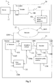
- Figure 1 shows a block diagram of an infrastructure 1 implementing the invention according to an embodiment.
- the infrastructure 1 comprises:
- the transmitter 10 comprises:
- the encoder 100 is connected to the source 11 by a connection 1000 and to the network 12 by a connection 1001.
- the error correction stream generator 102 is connected to the encoder 100 by the connection 1001, and is optionally connected to the reception quality monitor by a connection 1005.
- the reception quality monitor 101 is connected to the network 12 by the connections 1003 and 1004.
- the receiver 13 comprises:
- the network interface 130 is connected to the network 12 by a connection 1200.
- the reception memory is connected to the network interface 130 by a connection 1300, by which the data stream is sent.
- the error corrector 133 is connected to the network interface 130 by two connections 1304 and 1305.
- the decoder 132 is connected to the reception buffer 131 by a connection 1301.
- the error corrector 133 is connected to the reception buffer 131 by a connection 1306.
- the decoder output corresponds to a connection 1302.
- the source 11 provides data to be transmitted to the transmitter 10.
- the transmitter 10 receives this data, for example video data, in an encoder which encodes video data to a video stream compressed for example according to the standard H.264.
- the compressed stream that is output by the encoder is provided to the error correction stream generator 102, and also by the network 12 to the receiver 13.
- the error correction stream generator transmits one or several error correction streams associated with the data stream to the receiver 13 through the network 12 and the connection 1005.
- the reception quality monitor 101 receives the item of information representative of the reception quality of the receiver data flow 13 by the connection 1003. Then, the monitor 101 transmits by the connection 1004 a signal which indicates a change in state of activation of an error correction by the use of one or several error correction streams, according to a reception quality determined from the item of information received by the connection 1003.
- the receiver 13 receives the data stream 1300 and one or several error correction streams transmitted through the connection 1305 associated with the data stream transmitted via the connection 1300.
- the receiver 13 also receives a signal of change in state of activation 1304 transmitted by the transmitter 10 via its connection 1200 to the network 12, and can in return transmit an item of information representative of the reception quality of the data stream 1303, that the transmitter receives via the connection 1003.
- the reception memory 131 is used as buffer, allowing a certain number of packets to be stored.
- the packet flow which exits the reception memory 131 feeds a decoder 132 by a connection 1301.
- the decoder 132 sends the decoded data stream on the link 1302.
- the error corrector 133 receives one or several error correction streams associated with the data stream through the connection 1305.
- the error corrector also receives a signal of change in state of activation of an error correction through the link 1304. According to the signal state, the error corrector 133 corrects or does not correct the data stream packets in the reception memory 131, using or not the error correction stream(s) received through the connection 1305.
- the receiver 13 receives a data stream and one or several associated error corrections, and changes the state of activation of an error correction according to one or several criteria of change in the state of activation of an error correction.
- the receiver 13 includes a reception quality data collector 134 which reads in the reception memory via a connection 1307 to collect there an item of information representative of the reception quality, this item of information is then sent to the transmitter 10 by the connection 1301 which connects it to the network interface 130.
- a reception quality data collector 134 which reads in the reception memory via a connection 1307 to collect there an item of information representative of the reception quality, this item of information is then sent to the transmitter 10 by the connection 1301 which connects it to the network interface 130.
- the transmitter 10 can determine a reception quality, from the item of information received from one or several receivers, that is to say from receivers equipped with a collector 134 as described.
- the advantage of this is to allow the transmitter 10 to receive information about the reception quality of a limited number of receivers. This enables a reduction of the packet traffic on the network, and limits the impact on the CPU load of the transmitter (which processes less data) as well as the receivers, only one part of which, advantageously, collects information about the reception quality.
- the receiver sends the item of information representative of the reception quality of the data stream periodically. This has the advantage for a transmitter according to the invention to be constantly informed about the reception quality of a data stream by at least one receiver.
- the receiver sends the item of information representative of the reception quality of the data stream in case of reception quality change. This has the advantage of limiting the traffic of messages circulating on the network.
- the receiver sends the item of information representative of the reception quality of the data stream if a reception quality threshold is exceeded. This has the advantage of limiting the traffic of messages circulating in the network.
- the receiver sends the item of information representative of the reception quality of the data stream in case of zapping.
- the collector 134 of the receiver 13 uses a connection 1308 which connects it to the decoder 132, enabling the number of video freezes to be observed, an item of information which is, in this case, included in the item of information representative of the reception quality.
- the determination of the reception quality of the data stream by the transmitter 10 includes a number of video freezes observed by at least one receiver, detected from the item of information sent through the connection 1308 between the decoder 132 and the collector 134.
- the reception quality collector comprises a number of macroblocks observed in a video stream (a macroblock is a video image artefact, due to a decoding error, for example due to a packet loss) and detected from the item of information sent via the connection 1308 from the decoder 132 to the collector 134.
- a macroblock is a video image artefact, due to a decoding error, for example due to a packet loss
- the reception quality collector 134 of the receiver 13 collects an item of information about a number of lost packets, this item of information being in this case included in the item of information representative of the reception quality. This enables having direct information on the reception quality of one or several data streams.
- variant implementations of the invention described above comprising a receiver 13 with a reception quality data collector 134 can be combined to include more data in the item of information representative of the reception quality, sent by the receiver 13.
- the reception quality monitor 101 of the transmitter 10 controls the error correction stream generator 102 via the connection 1002, in order to reinforce or lighten the error correction stream according to the reception quality determined.
- the transmission of a column FEC coding is sufficient for a reception quality determined as being average, but the transmission of a column and line FEC coding is necessary for a reception quality determined as being bad.
- This has the advantage, for example, of enabling the impact on the occupation of the network bandwidth of network 12 as well as limiting the impact of using the error correction stream by the receiver 13, for example in terms of zapping time.
- the signal of change in state of activation of an error correction transmitted by the monitor 101 is inserted in the data stream. This has the advantage of not to oblige a receiver which implements the method of reception of the invention to put into place a specific connection for the reception of a signal of change in state of activation of error correction.
- Figure 2 shows a block diagram of an infrastructure 2 implementing the invention according to another embodiment.
- Figure 2 comprises some elements which have already been described for the figure 1 , which have a similar function in the figure 2 and which have the same references.
- the infrastructure 2 comprises:
- the transmitter 20 comprises:
- the receiver 22 comprises:
- the transmitter 20 of figure 2 does not include a reception quality monitor 101.
- a component with a similar function is placed in the receiver 22.
- the receiver 22 of figure 2 includes a reception quality monitor 220. In figure 2 , it is the reception quality monitor 220 which provides a signal of change in state to the error corrector 133 through the connection 1304; in figure 1 , this signal is sent by the transmitter 20.
- the transmitter 20 sends one or several error correction streams transmitted by the error correction stream generator 102.
- This error correction stream is associated with a data stream transmitted by the encoder 100.
- the receiver 22 determines itself the reception quality using the reception quality monitor 220 and realizes a change in state of activation through the transmission of a change in state of activation signal to the error corrector 133 through the connection 1304. This change is realized according to a criterion of change in state of activation of an error correction, the criterion being the reception quality in this implementation.
- the error corrector 133 uses or not the error correction stream(s) associated with the data stream.
- the reception quality monitor 220 of the receiver 22 comprises a connection coming from the decoder 132, which enables it to observe the number of video freezes.
- the reception quality monitor 220 comprises the number of macroblocks observed in a video stream. This item of information is in this case taken into account in the determination of the reception quality.
- the reception quality monitor 220 collects the item of information representative of the reception quality of the data stream during a zapping. Then, the information collection is realized during the connection to the data stream, which in practice can provide a good idea of the reception quality a receiver can expect, and this enables the use of the error correction stream to be activated or deactivated and limit the impact on the decoding, because taking one or several error correction streams into account or not is in this case carried out at the connection time and not during the connection, which avoids decoding errors.
- the reception quality monitor 220 collects the item of information representative of the reception quality of the stream in a periodical manner.
- the signal of change in state of activation is transmitted by the reception quality monitor 220 when the reception quality determined by this one exceeds a predetermined threshold.
- a signal of change in state of activation "switch on” is sent when the number of lost packets reaches the threshold of 3%, or when the number of video freezes exceeds the threshold of 1 video freeze per minute, or when the number of macroblocks in a video image exceeds 1 macroblock per 5 minutes.
- a "switch off signal is sent when the number of lost packets or the number of video freezes goes below this threshold.
- a change delay or taking into account a margin in the thresholds can be implemented to avoid a switching back and forth between the sending of a signal of change in state. For example, once the "switch on” signal is sent, a “switch off signal is sent only after a certain time during which no reception error is noted, or, once the "switch on” signal is sent after having noted that a threshold of 3% of lost packets has been exceeded, the "switch off signal will be sent only when the percentage of lost packets goes below the threshold of 1%.
- the signal of change in state is transmitted when the reception quality reaches a predetermined value, such as for example ten lost packets, or when a video freeze is observed.
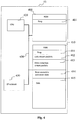
- FIG. 3 illustrates schematically the transmitter 10 of figure 1 according to a particular embodiment of the invention.
- the transmitter 10 comprises, interconnected by an address and data bus 350:
- register used in the description of memories described here designates in each of the memories mentioned with regard to figures 3 and 4 , a memory area of low capacity (some binary data) as well as a memory area of large capacity (enabling a whole programme to be stored or all or part of the data transmitted or received).
- the ROM memory 300 includes among others:
- the algorithms implementing the steps of the method described hereafter are stored in the memory ROM 300 associated with the transmitter 10 implementing these steps.
- the CPU 320 loads and executes the instructions of these algorithms.
- the Random Access Memory 310 comprises notably:
- FIG. 4 diagramatically illustrates a receiver 13 from figure 1 according to a particular embodiment of the invention.
- the receiver 13 comprises the following elements, connected together by an address and data bus 450:
- the ROM memory 400 comprises notably:
- the algorithms implementing the steps of the method described hereafter are stored in the ROM memory 400 associated with the receiver 13 implementing these steps. Upon powering up, the CPU 420 loads and executes the instructions of these algorithmes.
- the Random Access Memory 410 comprises notably:
- the invention is implemented according to a pure hardware realisation, for example in the form of a dedicated component (for example in an ASIC (Application Specific Integrated Circuit) or FPGA (Field-Programmable Gate Array) or VLSI (Very Large Scale Integration) or of several electronic components embedded in an apparatus or even in a form of a mix of hardware elements and software elements.
- a dedicated component for example in an ASIC (Application Specific Integrated Circuit) or FPGA (Field-Programmable Gate Array) or VLSI (Very Large Scale Integration) or of several electronic components embedded in an apparatus or even in a form of a mix of hardware elements and software elements.
- ASIC Application Specific Integrated Circuit
- FPGA Field-Programmable Gate Array
- VLSI Very Large Scale Integration
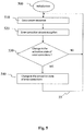
- Figure 5 represents, in algorithm form, a reception method according to the invention implemented in the receiver 13 or 22.
- the reception method starts with a step 500 during which different variables required for its correct operation are initialized.
- the receiver 13 or 22 receives a data stream.
- step 520 the receiver 13 or 22 receives one or more error correction streams.
- step 520 is carried out totally or in part, before or at the same time as step 510.
- the receiver 13 or 22 checks if a change in the state of activation of an error correction would be useful or necessary, for example according to the criteria such as those cited below.
- step 510 In the negative, no state of activation change is carried out, and step 510 is reiterated.
- the reception method comprises a reception step of a request to send information representative of the reception quality of the data stream.
- At least one change in the state of activation of an error correction criterium comprises one or more of the following criteria:
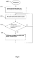
- Figure 6 represents, in algorithm form, a transmission method according to the invention implemented in the transmitter 10.
- the transmission method starts with a step 600 during which different variables required for its correct operation are initialized.
- the transmitter 10 transmits a data stream with at least one associated error correction stream.
- the transmitter 10 receives an item of information representative of the reception quality of at least one receiver.
- the transmitter 10 checks if a change in the state of activation of an error correction would be useful or necessary, according to at least one criterium of change in the state of activation of an error correction.
- step 620 In the negative, no signal of change in state of activation is transmitted, and step 620 is reiterated.
- At least one criterium of change in state of activation of an error correction comprises one or more of the following criteria:
- the method of transmission comprises a transmission step of a request for the transmission of information representative of the quality of reception of data stream. This also enables to only receive information from certain receivers, for example in particular receivers that are in a part of the network where the reception must be tested more precisely.
- the change in the state of activation of an error correction is carried out when the value of at least one criterium is greater than a maximal value of one or more determined criteria, or less than a minimal value of one or more determined criteria. For example, if the maximal value of the number of video freezes is equal to five, when the number of video freezes exceeds five video freezes per hour, a change in the state of activation of an error correction to a "switch on" state is performed. If the minimal value of the number of video freezes is equal to one, when the number of video freezes passes below one video freeze per hour, a change in the state of activation of an error correction to a "switch off" state is performed.
- the change in the state of activation of an error correction is carried out when a value relative to at least one criterium is exceeded. For example, when the number of packets lost becomes greater than 2% of the number of packets of the data stream received, change in state of activation of an error correction to a "switch on" state is performed. When the number of packets lost becomes less than 0.1% of the number of packets of the data stream received, a change in state of activation of an error correction "switch off" is performed.
- possible conflicts can be managed by attributing a priority level relative to each criterium, or by attributing a logical operation: for example, if the number of freezes exceeds a maximal threshold, but the number of packets lost is below the minimal value, a change in the state of activation of an error correction "switch on" is performed, the criterium of the number of video freezes being more important in the determination of reception quality (the highest priority is given to the criterium for the number of video freezes). If the number of packets lost passes below a minimal threshold, the change in state of activation is however not carried out if the number of video freezes has not passed below a minimal threshold (AND logical operation).
- the measurement of these criteria can be made continuously, or periodically, randomly or during an event (for example during zapping). These different ways of taking the measurement for the reception quality can be combined together.
- steps of the method for reception and of the method for transmission can be executed in parallel, such as the reception of frames, encapsulation, and the transmission, by adding means of communication and buffer memory zones between these steps.
- This has notably the advantage of enabling a separation of specific tasks.
- reception method as well as the transmission method can be implemented not only by a single device, but by a set of distinct devices.
- the architecture of infrastructures 1 and 2 as described by figures 1 and 2 can comprise other devices required for correct operation.
- a management server can manage the transmitter or transmittors via a LAN (Local Access Network) internal network.
- LAN Local Access Network
- Such a management server can also manage the subscriptions of users of receivers to different service offers.
- items of network equipment such as routers and switches and specific for the transport protocol used can be necessary to access to the network 12.
- the network 12 is a network commonly called an optical fibre "backbone" with ATM protocol, enabling a very high bitrate and a guaranteed bitrate.
- the receivers are connected to this backbone by distribution centres comprising DSLAMs (Digital Subscriber Line Access Multiplexer).
- DSLAMs Digital Subscriber Line Access Multiplexer
- a receiver accesses a DSLAM via a telephone line and an ADSL (Asynchronous Digital Subscriber Line) modem.
- the receiver accesses to the network 12 via a specific access device (gateway) comprising an ADSL modem, a router, a Firewall, a wireless transmitter / receiver, etc, and can connect more than one receivers to it at the same time.
- a specific access device comprising an ADSL modem, a router, a Firewall, a wireless transmitter / receiver, etc, and can connect more than one receivers to it at the same time.
- the type of network used can be wired, as shown here, but also wireless, using techniques such as WiFi, DVB-H (standard DVB for wireless portable devices), DVB-T (standard DVB for the reception of digital television and radio via terrestrial signal), or DVB-S (standard DVB for the reception of digital television and radio via satellite signal) or again according to the standard ATSC (Advanced Television Systems Comittee).
- DVB-H standard DVB for wireless portable devices
- DVB-T standard DVB for the reception of digital television and radio via terrestrial signal
- DVB-S standard DVB for the reception of digital television and radio via satellite signal
- ATSC Advanced Television Systems Comittee
- the architecture of the devices featuring in the infrastructures 1 and 2 of figures 1 and 2 can be different.
- several generators of error correction streams can be added to provide error correction stream(s) particularly adapted to a section of the set of receivers.
- the error corrector 133 of a receiver 13 or 22 according to respectively figures 1 or 2 links the reception memory 131 to the decoder 132.
- the method for reception, as well as the method for transmission can be implemented using configuration, administration, control and diagnostic protocols, according to for example the protocol SNMP or the protocol CWMP an its extensions (Consumer Premises Equipment - Wide Area Network Management Protocol).
- the invention can be implemented using the protocol SNMP (Simple Network Management Protocol) positioning an SNMP "manager” at the level of the transmitter and an SNMP "agent” in the receiver and adding an MIB (Management Information Base) with a specific attribute for the management of change in the state of activation of an error correction by use of one or more error correction streams.
- an "MIB attribute" can be added at the level of the receivers, known as "fecConfiguration" of the enumerated type, admitting the values described hereafter, accessible in read and write:
- the value FEC_NONE signifies that no error correction by use of one or more error correction streams is to be done by the receiver.
- the value FEC_FORCED signifies that the receiver must necessarily use the error correction stream or streams.
- the value FEC_AUTO signifies that the receiver must determine itself if a change in the state of activation of an error correction by use of one or more error correction streams is to be performed, according to the criteria as described here previously. In the first two cases (FEC_NONE and FEC_FORCED), it is the transmitter that determines if a change in the state of activation of an error correction by use of one or more error correction streams is necessary, according to one or more criteria as described here previously.
- the invention can also be implemented using the protocol CWMP and by adding an ACS (Auto Configuration Server) at transmitter level.
- a CWMP agent is added as well as an object in the receiver comprising the specific attributes for the management of change in the state of activation of an error correction by use of one or more error correction streams.
- the receiver is called the CPE, and for one CPE there are two error correction activation modes: a "forced” mode and an "automatic” mode.
- “forced” mode the CPE changes the state of activation of an error correction by use of one or more correction streams according to a signal of change in state, sent by a transmitter; it is the transmitter that determines the change in state according to at least one change criterium.
- a FEC object is added in the data structure as defined by the standard TR-135 (defined by the Broadband Forum). This FEC object is part of the object .STBService. ⁇ i ⁇ .Components.FrontEnd. ⁇ i ⁇ .IP as defined in TR-135.
- This FEC object contains the following four parameters:
- the first two (Enable, ForceFECEnable) are parameters in write only access.
- the next two (OperationMode, AutoModeFECDecoderStatus) are in read only access.
- the Enable parameter is of boolean type. It enables activation or deactivation of the FEC module. Writing of the value 1 in the Enable parameter causes the activation of the FEC module in automatic operating mode. This means that the receiver must determine itself if a change in the state of activation of an error correction by use of one or more error correction streams is to be performed, according to the criteria described here previously. Writing the value 0 in the Enable parameter causes the FEC module to be deactivated this means that no error correction by the use of one or more error correction streams is to be performed by the receiver. Writing 0 or 1 in the Enable parameter is done using the method SetParameterValue of protocol CWMP of Tr-069.
- ForceFECEnable is a boolean type parameter. Writing the value 1 in the parameter Enable causes the activation of the FEC module in forced operating mode. This means that the receiver must necessarily use the errror correction stream(s).
- the transmitter determines if a change in the state of activation of an error correction by use of one or more error correction streams is necessary, according to one or more criteria such as those described here previously.
- the receiver decides on the activation or not of an error correction by use of one or more error correction streams, according to one or more criteria such as those described here previously.
- OperationMode is a enumerated type parameter and contains a description in the form of character string of the operating mode of the receiver. "Disabled” indicates that the FEC is not activated. "Auto” indicates that the operating mode of the FEC is automatic (as described previously). The value “Forced” indicates that the activation was forced.
- AutoModeFECDecoderStatus indicates, in the case where the operating mode is automatic, if the FEC decoder is operating or not. "FEC-ON” indicates that the receiver uses the FEC data to perform an error correction. “FEC-OFF” indicates that the receiver does not use the FEC data to perform an error correction.
- the SNMP protocol is defined in a series of documents called RFCs (Request For Comment), such as RFC 1157: "A Simple Network Management Protocol ".
- the CWMP protocol is defined by the document TR-069 and its various amendments and extensions (TR-098, TR-104, TR-106, TR-110, TR-111, TR-135, TR-140 et TR-142).
- MIB attributes can be put in place to manage the correction of errors by the use of one or more error correction streams.
- errorCorrection can be defined, that can take the values “on”, “off”, “auto”, for "switch on”, “switch off”, that is to say forced by a transmitter, and for 'automatic", that is to say to be determined by the receiver itself.
- MIB attributes can be put in place, to manage the change in state function, for example by separating the parameters that can be written from those that can be read by a transmitter.
- an error correction by use of one or more error correction streams can not use FEC codes, but for example Reed-Solomon.
- the parameters can be combined together to simplify their use and limit the number of messages necessary between a receiver and a transmitter.
Landscapes
- Engineering & Computer Science (AREA)
- Signal Processing (AREA)
- Multimedia (AREA)
- Computer Networks & Wireless Communication (AREA)
- Databases & Information Systems (AREA)
- Detection And Prevention Of Errors In Transmission (AREA)
- Quality & Reliability (AREA)
- Two-Way Televisions, Distribution Of Moving Picture Or The Like (AREA)
- Data Exchanges In Wide-Area Networks (AREA)
- Communication Control (AREA)
Priority Applications (1)
| Application Number | Priority Date | Filing Date | Title |
|---|---|---|---|
| PL09772405T PL2297960T3 (pl) | 2008-06-30 | 2009-06-29 | Sposób odbierania strumieni danych oraz odpowiedni sposób przesyłania |
Applications Claiming Priority (2)
| Application Number | Priority Date | Filing Date | Title |
|---|---|---|---|
| FR0854400A FR2933263A1 (fr) | 2008-06-30 | 2008-06-30 | Methode de reception de flux de donnees et methode d'emission correspondante |
| PCT/EP2009/058127 WO2010000705A1 (en) | 2008-06-30 | 2009-06-29 | Method for receiving data streams and corresponding method for transmission |
Publications (2)
| Publication Number | Publication Date |
|---|---|
| EP2297960A1 EP2297960A1 (en) | 2011-03-23 |
| EP2297960B1 true EP2297960B1 (en) | 2019-08-21 |
Family
ID=40677513
Family Applications (1)
| Application Number | Title | Priority Date | Filing Date |
|---|---|---|---|
| EP09772405.8A Active EP2297960B1 (en) | 2008-06-30 | 2009-06-29 | Method for receiving data streams and corresponding method for transmission |
Country Status (11)
| Country | Link |
|---|---|
| US (1) | US8516345B2 (ko) |
| EP (1) | EP2297960B1 (ko) |
| JP (1) | JP5559780B2 (ko) |
| KR (2) | KR101689789B1 (ko) |
| CN (1) | CN102077593B (ko) |
| BR (1) | BRPI0914732B1 (ko) |
| ES (1) | ES2754818T3 (ko) |
| FR (1) | FR2933263A1 (ko) |
| MX (1) | MX2010013962A (ko) |
| PL (1) | PL2297960T3 (ko) |
| WO (1) | WO2010000705A1 (ko) |
Families Citing this family (16)
| Publication number | Priority date | Publication date | Assignee | Title |
|---|---|---|---|---|
| US10097946B2 (en) * | 2011-12-22 | 2018-10-09 | Taiwan Semiconductor Manufacturing Co., Ltd. | Systems and methods for cooperative applications in communication systems |
| US9668083B2 (en) | 2011-12-22 | 2017-05-30 | Taiwan Semiconductor Manufacturing Co., Ltd. | Systems and methods for cooperative applications in communication systems |
| US20120192039A1 (en) * | 2009-07-03 | 2012-07-26 | Miska Hannuksela | Method, Apparatuses and Service for Media Transmission |
| CN104041016B (zh) * | 2012-02-06 | 2017-05-17 | 松下电器产业株式会社 | 服务器装置及系统控制方法 |
| CN103686055B (zh) * | 2012-09-24 | 2017-05-10 | 中兴通讯股份有限公司 | 电视会议系统中丢包补偿的处理方法及装置 |
| US20150089073A1 (en) * | 2013-09-25 | 2015-03-26 | Ericsson Television Inc | System and method for effectuating fast channel change in an adpative streaming environment |
| DE102016101023A1 (de) * | 2015-01-22 | 2016-07-28 | Sennheiser Electronic Gmbh & Co. Kg | Digitales Drahtlos-Audioübertragungssystem |
| KR101671018B1 (ko) * | 2015-04-22 | 2016-10-31 | (주)이즈미디어 | 스큐 자동 보정 방법 및 장치 |
| CA3001480C (en) * | 2015-10-16 | 2019-06-18 | Tribune Broadcasting Company, Llc | Video-production system with dve feature |
| TWI622306B (zh) * | 2016-06-08 | 2018-04-21 | Chunghwa Telecom Co Ltd | Public wireless local area network circuit quality measurement system and method |
| US10705898B2 (en) * | 2017-04-27 | 2020-07-07 | Arxan Technologies, Inc. | Transmitting surreptitious data on an existing communication channel |
| US11411989B2 (en) * | 2017-04-27 | 2022-08-09 | Arxan Technologies, Inc. | Transmitting surreptitious data on an existing communication channel |
| KR102027402B1 (ko) * | 2017-10-31 | 2019-10-02 | (주)이씨스 | 프레임 제어 메시지 슬롯을 이용한 노변 기지국의 통신 영역에 대한 검증 장치 및 방법 |
| US10966001B2 (en) * | 2018-04-05 | 2021-03-30 | Tvu Networks Corporation | Remote cloud-based video production system in an environment where there is network delay |
| US11463747B2 (en) | 2018-04-05 | 2022-10-04 | Tvu Networks Corporation | Systems and methods for real time control of a remote video production with multiple streams |
| US11212431B2 (en) | 2018-04-06 | 2021-12-28 | Tvu Networks Corporation | Methods and apparatus for remotely controlling a camera in an environment with communication latency |
Citations (1)
| Publication number | Priority date | Publication date | Assignee | Title |
|---|---|---|---|---|
| EP1672318A2 (en) * | 2004-12-15 | 2006-06-21 | Pioneer Corporation | Remote reproduction system and remote reproduction method |
Family Cites Families (12)
| Publication number | Priority date | Publication date | Assignee | Title |
|---|---|---|---|---|
| US6625776B1 (en) * | 1998-09-30 | 2003-09-23 | Northrop Grumman Corporation | Adaptive coding scheme for a processing communications satellite |
| US6757860B2 (en) * | 2000-08-25 | 2004-06-29 | Agere Systems Inc. | Channel error protection implementable across network layers in a communication system |
| US6909753B2 (en) * | 2001-12-05 | 2005-06-21 | Koninklijke Philips Electronics, N.V. | Combined MPEG-4 FGS and modulation algorithm for wireless video transmission |
| JP2003234687A (ja) * | 2002-02-06 | 2003-08-22 | Nippon Telegr & Teleph Corp <Ntt> | 無線通信システム |
| MXPA05008094A (es) | 2003-01-28 | 2006-02-08 | Thomson Licensing | Formacion escalonada de modo robusto. |
| US20060072837A1 (en) * | 2003-04-17 | 2006-04-06 | Ralston John D | Mobile imaging application, device architecture, and service platform architecture |
| US7992068B2 (en) | 2003-10-06 | 2011-08-02 | Ipg Electronics 503 Limited | Digital television transmission with error correction |
| JP4891779B2 (ja) * | 2003-12-07 | 2012-03-07 | アダプティブ スペクトラム アンド シグナル アラインメント インコーポレイテッド | 適応マージン制御及び適応帯域制御 |
| US7653014B2 (en) * | 2004-03-18 | 2010-01-26 | Intel Corporation | Configuring a transmission mode between devices |
| JP4573663B2 (ja) * | 2005-02-16 | 2010-11-04 | 富士通株式会社 | データ中継装置、データ中継方法、データ送受信装置およびデータ通信システム |
| JP4666309B2 (ja) * | 2006-03-07 | 2011-04-06 | 財団法人エヌエイチケイエンジニアリングサービス | 送信装置、受信装置、中継装置及びパケット伝送システム |
| US8170606B2 (en) * | 2008-10-15 | 2012-05-01 | Apple Inc. | Dynamic thermal control for wireless transceivers |
-
2008
- 2008-06-30 FR FR0854400A patent/FR2933263A1/fr active Pending
-
2009
- 2009-06-29 BR BRPI0914732-2A patent/BRPI0914732B1/pt active IP Right Grant
- 2009-06-29 EP EP09772405.8A patent/EP2297960B1/en active Active
- 2009-06-29 ES ES09772405T patent/ES2754818T3/es active Active
- 2009-06-29 MX MX2010013962A patent/MX2010013962A/es active IP Right Grant
- 2009-06-29 WO PCT/EP2009/058127 patent/WO2010000705A1/en active Application Filing
- 2009-06-29 CN CN2009801254977A patent/CN102077593B/zh active Active
- 2009-06-29 KR KR1020167006098A patent/KR101689789B1/ko active IP Right Grant
- 2009-06-29 PL PL09772405T patent/PL2297960T3/pl unknown
- 2009-06-29 JP JP2011515415A patent/JP5559780B2/ja active Active
- 2009-06-29 KR KR1020107029619A patent/KR101604361B1/ko active IP Right Grant
- 2009-06-29 US US12/737,259 patent/US8516345B2/en active Active
Patent Citations (1)
| Publication number | Priority date | Publication date | Assignee | Title |
|---|---|---|---|---|
| EP1672318A2 (en) * | 2004-12-15 | 2006-06-21 | Pioneer Corporation | Remote reproduction system and remote reproduction method |
Non-Patent Citations (2)
| Title |
|---|
| MCCANNE S ET AL: "Receiver-driven Layered Multicast", COMPUTER COMMUNICATION REVIEW, ACM, NEW YORK, NY, US, no. 4, 1 October 1996 (1996-10-01), pages 117 - 130, XP002452811, ISSN: 0146-4833, DOI: 10.1145/248157.248168 * |
| QUACCHIA ET AL: "TR-135. DATA MODEL FOR A TR-069 ENABLED STB", INTERNET CITATION, 31 December 2007 (2007-12-31), pages 1 - 114, XP002512769, Retrieved from the Internet <URL:http://www.broadband-forum.org/technical/download/TR-135.pdf> [retrieved on 20090130] * |
Also Published As
| Publication number | Publication date |
|---|---|
| KR101689789B1 (ko) | 2016-12-26 |
| MX2010013962A (es) | 2011-02-15 |
| CN102077593A (zh) | 2011-05-25 |
| JP5559780B2 (ja) | 2014-07-23 |
| BRPI0914732A2 (pt) | 2015-10-20 |
| KR20110039424A (ko) | 2011-04-18 |
| KR20160033789A (ko) | 2016-03-28 |
| ES2754818T3 (es) | 2020-04-20 |
| US20110179320A1 (en) | 2011-07-21 |
| FR2933263A1 (fr) | 2010-01-01 |
| KR101604361B1 (ko) | 2016-03-25 |
| US8516345B2 (en) | 2013-08-20 |
| WO2010000705A1 (en) | 2010-01-07 |
| JP2011526750A (ja) | 2011-10-13 |
| BRPI0914732B1 (pt) | 2021-01-26 |
| PL2297960T3 (pl) | 2020-03-31 |
| EP2297960A1 (en) | 2011-03-23 |
| CN102077593B (zh) | 2013-12-18 |
Similar Documents
| Publication | Publication Date | Title |
|---|---|---|
| EP2297960B1 (en) | Method for receiving data streams and corresponding method for transmission | |
| US7865581B2 (en) | Remote management method of a distant device, and corresponding video device | |
| US7380028B2 (en) | Robust delivery of video data | |
| US8826102B2 (en) | Method and system for adapting forward error correction in multicast over wireless networks | |
| US8750385B2 (en) | Video data loss recovery using low bit rate stream in an IPTV system | |
| US7047456B2 (en) | Error correction for regional and dynamic factors in communications | |
| US20100296428A1 (en) | A robust system and method for wireless data multicasting using superposition modulation | |
| EP1241837A1 (en) | Transmitting/receiving method and device therefor | |
| US8621544B2 (en) | Mitigatation of video artifacts | |
| US20080068990A1 (en) | Method and apparatus for implementing multicast service | |
| Wang et al. | Low-delay and error-robust wireless video transmission for video communications | |
| KR101353404B1 (ko) | 디지털 텔레비전 방송 서비스를 수신하기 위한 게이트웨이,단말기 및 대응 방법 | |
| US20120093144A1 (en) | Optimized method of transmitting layered contents to mobile terminals and via a radio infrastructure with access procedure of tdm/tdma/ofdma type, and associated processing device | |
| Nazir et al. | Unequal error protection for data partitioned H. 264/AVC video broadcasting | |
| Gardikis et al. | Satellite media broadcasting with adaptive coding and modulation | |
| Barsocchi et al. | Quality of experience in multicast hybrid networks: avoiding bandwidth wasting with a double-stage FEC Scheme | |
| Khayam et al. | A statistical receiver-based approach for improved throughput of multimedia communications over wireless LANs | |
| Karande et al. | Survival Of The Fittest: An active queue management technique for noisy packet flows | |
| Barsocchi et al. | A novel approach for multicast video streaming in hybrid networks | |
| Servetto et al. | Video multicast over fair queueing networks | |
| JP2009194707A (ja) | 通信装置、通信システム及び通信方法 |
Legal Events
| Date | Code | Title | Description |
|---|---|---|---|
| PUAI | Public reference made under article 153(3) epc to a published international application that has entered the european phase |
Free format text: ORIGINAL CODE: 0009012 |
|
| 17P | Request for examination filed |
Effective date: 20101220 |
|
| AK | Designated contracting states |
Kind code of ref document: A1 Designated state(s): AT BE BG CH CY CZ DE DK EE ES FI FR GB GR HR HU IE IS IT LI LT LU LV MC MK MT NL NO PL PT RO SE SI SK TR |
|
| AX | Request for extension of the european patent |
Extension state: AL BA RS |
|
| DAX | Request for extension of the european patent (deleted) | ||
| 17Q | First examination report despatched |
Effective date: 20160906 |
|
| STAA | Information on the status of an ep patent application or granted ep patent |
Free format text: STATUS: EXAMINATION IS IN PROGRESS |
|
| REG | Reference to a national code |
Ref country code: DE Ref legal event code: R079 Ref document number: 602009059554 Country of ref document: DE Free format text: PREVIOUS MAIN CLASS: H04N0007240000 Ipc: H04N0021238300 |
|
| RAP1 | Party data changed (applicant data changed or rights of an application transferred) |
Owner name: INTERDIGITAL CE PATENT HOLDINGS |
|
| GRAP | Despatch of communication of intention to grant a patent |
Free format text: ORIGINAL CODE: EPIDOSNIGR1 |
|
| STAA | Information on the status of an ep patent application or granted ep patent |
Free format text: STATUS: GRANT OF PATENT IS INTENDED |
|
| RIC1 | Information provided on ipc code assigned before grant |
Ipc: H04N 21/2383 20110101AFI20190206BHEP Ipc: H04N 19/169 20140101ALI20190206BHEP Ipc: H04N 21/658 20110101ALI20190206BHEP Ipc: H04N 21/2389 20110101ALI20190206BHEP Ipc: H04N 21/4385 20110101ALI20190206BHEP Ipc: H04N 19/102 20140101ALI20190206BHEP Ipc: H04N 21/442 20110101ALI20190206BHEP Ipc: H04N 21/6379 20110101ALI20190206BHEP Ipc: H04N 19/154 20140101ALI20190206BHEP Ipc: H04N 21/6377 20110101ALI20190206BHEP Ipc: H04N 19/166 20140101ALI20190206BHEP Ipc: H04N 19/67 20140101ALI20190206BHEP |
|
| INTG | Intention to grant announced |
Effective date: 20190312 |
|
| GRAS | Grant fee paid |
Free format text: ORIGINAL CODE: EPIDOSNIGR3 |
|
| GRAA | (expected) grant |
Free format text: ORIGINAL CODE: 0009210 |
|
| STAA | Information on the status of an ep patent application or granted ep patent |
Free format text: STATUS: THE PATENT HAS BEEN GRANTED |
|
| AK | Designated contracting states |
Kind code of ref document: B1 Designated state(s): AT BE BG CH CY CZ DE DK EE ES FI FR GB GR HR HU IE IS IT LI LT LU LV MC MK MT NL NO PL PT RO SE SI SK TR |
|
| REG | Reference to a national code |
Ref country code: GB Ref legal event code: FG4D |
|
| REG | Reference to a national code |
Ref country code: CH Ref legal event code: EP |
|
| REG | Reference to a national code |
Ref country code: DE Ref legal event code: R096 Ref document number: 602009059554 Country of ref document: DE |
|
| REG | Reference to a national code |
Ref country code: AT Ref legal event code: REF Ref document number: 1171089 Country of ref document: AT Kind code of ref document: T Effective date: 20190915 |
|
| REG | Reference to a national code |
Ref country code: IE Ref legal event code: FG4D |
|
| REG | Reference to a national code |
Ref country code: SE Ref legal event code: TRGR |
|
| REG | Reference to a national code |
Ref country code: NL Ref legal event code: FP |
|
| REG | Reference to a national code |
Ref country code: LT Ref legal event code: MG4D |
|
| PG25 | Lapsed in a contracting state [announced via postgrant information from national office to epo] |
Ref country code: FI Free format text: LAPSE BECAUSE OF FAILURE TO SUBMIT A TRANSLATION OF THE DESCRIPTION OR TO PAY THE FEE WITHIN THE PRESCRIBED TIME-LIMIT Effective date: 20190821 Ref country code: LT Free format text: LAPSE BECAUSE OF FAILURE TO SUBMIT A TRANSLATION OF THE DESCRIPTION OR TO PAY THE FEE WITHIN THE PRESCRIBED TIME-LIMIT Effective date: 20190821 Ref country code: NO Free format text: LAPSE BECAUSE OF FAILURE TO SUBMIT A TRANSLATION OF THE DESCRIPTION OR TO PAY THE FEE WITHIN THE PRESCRIBED TIME-LIMIT Effective date: 20191121 Ref country code: BG Free format text: LAPSE BECAUSE OF FAILURE TO SUBMIT A TRANSLATION OF THE DESCRIPTION OR TO PAY THE FEE WITHIN THE PRESCRIBED TIME-LIMIT Effective date: 20191121 Ref country code: HR Free format text: LAPSE BECAUSE OF FAILURE TO SUBMIT A TRANSLATION OF THE DESCRIPTION OR TO PAY THE FEE WITHIN THE PRESCRIBED TIME-LIMIT Effective date: 20190821 Ref country code: PT Free format text: LAPSE BECAUSE OF FAILURE TO SUBMIT A TRANSLATION OF THE DESCRIPTION OR TO PAY THE FEE WITHIN THE PRESCRIBED TIME-LIMIT Effective date: 20191223 |
|
| PG25 | Lapsed in a contracting state [announced via postgrant information from national office to epo] |
Ref country code: IS Free format text: LAPSE BECAUSE OF FAILURE TO SUBMIT A TRANSLATION OF THE DESCRIPTION OR TO PAY THE FEE WITHIN THE PRESCRIBED TIME-LIMIT Effective date: 20191221 Ref country code: LV Free format text: LAPSE BECAUSE OF FAILURE TO SUBMIT A TRANSLATION OF THE DESCRIPTION OR TO PAY THE FEE WITHIN THE PRESCRIBED TIME-LIMIT Effective date: 20190821 Ref country code: GR Free format text: LAPSE BECAUSE OF FAILURE TO SUBMIT A TRANSLATION OF THE DESCRIPTION OR TO PAY THE FEE WITHIN THE PRESCRIBED TIME-LIMIT Effective date: 20191122 |
|
| REG | Reference to a national code |
Ref country code: AT Ref legal event code: MK05 Ref document number: 1171089 Country of ref document: AT Kind code of ref document: T Effective date: 20190821 |
|
| PG25 | Lapsed in a contracting state [announced via postgrant information from national office to epo] |
Ref country code: TR Free format text: LAPSE BECAUSE OF FAILURE TO SUBMIT A TRANSLATION OF THE DESCRIPTION OR TO PAY THE FEE WITHIN THE PRESCRIBED TIME-LIMIT Effective date: 20190821 |
|
| REG | Reference to a national code |
Ref country code: ES Ref legal event code: FG2A Ref document number: 2754818 Country of ref document: ES Kind code of ref document: T3 Effective date: 20200420 |
|
| PG25 | Lapsed in a contracting state [announced via postgrant information from national office to epo] |
Ref country code: EE Free format text: LAPSE BECAUSE OF FAILURE TO SUBMIT A TRANSLATION OF THE DESCRIPTION OR TO PAY THE FEE WITHIN THE PRESCRIBED TIME-LIMIT Effective date: 20190821 Ref country code: AT Free format text: LAPSE BECAUSE OF FAILURE TO SUBMIT A TRANSLATION OF THE DESCRIPTION OR TO PAY THE FEE WITHIN THE PRESCRIBED TIME-LIMIT Effective date: 20190821 Ref country code: DK Free format text: LAPSE BECAUSE OF FAILURE TO SUBMIT A TRANSLATION OF THE DESCRIPTION OR TO PAY THE FEE WITHIN THE PRESCRIBED TIME-LIMIT Effective date: 20190821 Ref country code: RO Free format text: LAPSE BECAUSE OF FAILURE TO SUBMIT A TRANSLATION OF THE DESCRIPTION OR TO PAY THE FEE WITHIN THE PRESCRIBED TIME-LIMIT Effective date: 20190821 |
|
| PG25 | Lapsed in a contracting state [announced via postgrant information from national office to epo] |
Ref country code: CZ Free format text: LAPSE BECAUSE OF FAILURE TO SUBMIT A TRANSLATION OF THE DESCRIPTION OR TO PAY THE FEE WITHIN THE PRESCRIBED TIME-LIMIT Effective date: 20190821 Ref country code: IS Free format text: LAPSE BECAUSE OF FAILURE TO SUBMIT A TRANSLATION OF THE DESCRIPTION OR TO PAY THE FEE WITHIN THE PRESCRIBED TIME-LIMIT Effective date: 20200224 Ref country code: SK Free format text: LAPSE BECAUSE OF FAILURE TO SUBMIT A TRANSLATION OF THE DESCRIPTION OR TO PAY THE FEE WITHIN THE PRESCRIBED TIME-LIMIT Effective date: 20190821 |
|
| REG | Reference to a national code |
Ref country code: DE Ref legal event code: R097 Ref document number: 602009059554 Country of ref document: DE |
|
| PLBE | No opposition filed within time limit |
Free format text: ORIGINAL CODE: 0009261 |
|
| STAA | Information on the status of an ep patent application or granted ep patent |
Free format text: STATUS: NO OPPOSITION FILED WITHIN TIME LIMIT |
|
| PG2D | Information on lapse in contracting state deleted |
Ref country code: IS |
|
| 26N | No opposition filed |
Effective date: 20200603 |
|
| PG25 | Lapsed in a contracting state [announced via postgrant information from national office to epo] |
Ref country code: SI Free format text: LAPSE BECAUSE OF FAILURE TO SUBMIT A TRANSLATION OF THE DESCRIPTION OR TO PAY THE FEE WITHIN THE PRESCRIBED TIME-LIMIT Effective date: 20190821 |
|
| PG25 | Lapsed in a contracting state [announced via postgrant information from national office to epo] |
Ref country code: MC Free format text: LAPSE BECAUSE OF FAILURE TO SUBMIT A TRANSLATION OF THE DESCRIPTION OR TO PAY THE FEE WITHIN THE PRESCRIBED TIME-LIMIT Effective date: 20190821 |
|
| REG | Reference to a national code |
Ref country code: CH Ref legal event code: PL |
|
| PG25 | Lapsed in a contracting state [announced via postgrant information from national office to epo] |
Ref country code: LU Free format text: LAPSE BECAUSE OF NON-PAYMENT OF DUE FEES Effective date: 20200629 |
|
| REG | Reference to a national code |
Ref country code: BE Ref legal event code: MM Effective date: 20200630 |
|
| PG25 | Lapsed in a contracting state [announced via postgrant information from national office to epo] |
Ref country code: IE Free format text: LAPSE BECAUSE OF NON-PAYMENT OF DUE FEES Effective date: 20200629 Ref country code: LI Free format text: LAPSE BECAUSE OF NON-PAYMENT OF DUE FEES Effective date: 20200630 Ref country code: CH Free format text: LAPSE BECAUSE OF NON-PAYMENT OF DUE FEES Effective date: 20200630 |
|
| PG25 | Lapsed in a contracting state [announced via postgrant information from national office to epo] |
Ref country code: BE Free format text: LAPSE BECAUSE OF NON-PAYMENT OF DUE FEES Effective date: 20200630 |
|
| PG25 | Lapsed in a contracting state [announced via postgrant information from national office to epo] |
Ref country code: MT Free format text: LAPSE BECAUSE OF FAILURE TO SUBMIT A TRANSLATION OF THE DESCRIPTION OR TO PAY THE FEE WITHIN THE PRESCRIBED TIME-LIMIT Effective date: 20190821 Ref country code: CY Free format text: LAPSE BECAUSE OF FAILURE TO SUBMIT A TRANSLATION OF THE DESCRIPTION OR TO PAY THE FEE WITHIN THE PRESCRIBED TIME-LIMIT Effective date: 20190821 |
|
| PG25 | Lapsed in a contracting state [announced via postgrant information from national office to epo] |
Ref country code: MK Free format text: LAPSE BECAUSE OF FAILURE TO SUBMIT A TRANSLATION OF THE DESCRIPTION OR TO PAY THE FEE WITHIN THE PRESCRIBED TIME-LIMIT Effective date: 20190821 |
|
| P01 | Opt-out of the competence of the unified patent court (upc) registered |
Effective date: 20230511 |
|
| PGFP | Annual fee paid to national office [announced via postgrant information from national office to epo] |
Ref country code: NL Payment date: 20230626 Year of fee payment: 15 Ref country code: FR Payment date: 20230622 Year of fee payment: 15 Ref country code: DE Payment date: 20230627 Year of fee payment: 15 |
|
| PGFP | Annual fee paid to national office [announced via postgrant information from national office to epo] |
Ref country code: SE Payment date: 20230626 Year of fee payment: 15 Ref country code: PL Payment date: 20230620 Year of fee payment: 15 |
|
| PGFP | Annual fee paid to national office [announced via postgrant information from national office to epo] |
Ref country code: IT Payment date: 20230620 Year of fee payment: 15 Ref country code: GB Payment date: 20230620 Year of fee payment: 15 Ref country code: ES Payment date: 20230720 Year of fee payment: 15 |