EP2297661B1 - Verfahren zum modellieren biomechanischer eigenschaften eines auges - Google Patents
Verfahren zum modellieren biomechanischer eigenschaften eines auges Download PDFInfo
- Publication number
- EP2297661B1 EP2297661B1 EP09735500.2A EP09735500A EP2297661B1 EP 2297661 B1 EP2297661 B1 EP 2297661B1 EP 09735500 A EP09735500 A EP 09735500A EP 2297661 B1 EP2297661 B1 EP 2297661B1
- Authority
- EP
- European Patent Office
- Prior art keywords
- eye
- tissue
- patient
- finite element
- model
- Prior art date
- Legal status (The legal status is an assumption and is not a legal conclusion. Google has not performed a legal analysis and makes no representation as to the accuracy of the status listed.)
- Active
Links
Images


Classifications
-
- G—PHYSICS
- G16—INFORMATION AND COMMUNICATION TECHNOLOGY [ICT] SPECIALLY ADAPTED FOR SPECIFIC APPLICATION FIELDS
- G16B—BIOINFORMATICS, i.e. INFORMATION AND COMMUNICATION TECHNOLOGY [ICT] SPECIALLY ADAPTED FOR GENETIC OR PROTEIN-RELATED DATA PROCESSING IN COMPUTATIONAL MOLECULAR BIOLOGY
- G16B5/00—ICT specially adapted for modelling or simulations in systems biology, e.g. gene-regulatory networks, protein interaction networks or metabolic networks
-
- G—PHYSICS
- G06—COMPUTING OR CALCULATING; COUNTING
- G06N—COMPUTING ARRANGEMENTS BASED ON SPECIFIC COMPUTATIONAL MODELS
- G06N5/00—Computing arrangements using knowledge-based models
- G06N5/02—Knowledge representation; Symbolic representation
-
- G—PHYSICS
- G16—INFORMATION AND COMMUNICATION TECHNOLOGY [ICT] SPECIALLY ADAPTED FOR SPECIFIC APPLICATION FIELDS
- G16H—HEALTHCARE INFORMATICS, i.e. INFORMATION AND COMMUNICATION TECHNOLOGY [ICT] SPECIALLY ADAPTED FOR THE HANDLING OR PROCESSING OF MEDICAL OR HEALTHCARE DATA
- G16H50/00—ICT specially adapted for medical diagnosis, medical simulation or medical data mining; ICT specially adapted for detecting, monitoring or modelling epidemics or pandemics
- G16H50/50—ICT specially adapted for medical diagnosis, medical simulation or medical data mining; ICT specially adapted for detecting, monitoring or modelling epidemics or pandemics for simulation or modelling of medical disorders
Definitions
- the present invention relates to systems and methods for evaluating the condition and properties of a mammalian eye, and, in particular, is directed to systems and methods for in vivo modeling of biomechanical properties of the eye.
- the cornea relies greatly upon its material properties in its roles as a mechanical barrier to injury and as a scaffold for the eye's primary refracting surface. These biomechanical properties influence the safety and optical predictability of surgery and play an important role in the pathogenesis and of diseases such as keratoconus and post-refractive surgery ectasia. Consequently, alteration of these properties by disease or surgery can have profound visual implications. Ectatic diseases such as keratoconus, pellucid marginal degeneration and keratoglobus are characterized by progressive thinning and distortion of the cornea, and as a class represent a leading indication for corneal transplantation. Identification of early ectasia is a major emphasis of preoperative refractive surgery evaluations, where it is imperative to avoid the potential destabilizing effects of laser vision correction in corneas that are predisposed to biomechanical instability or failure.
- a system for predicting the results of a therapeutic intervention for an eye of a patient.
- An imaging system is configured to provide image data representing at least a portion of the eye of the patient.
- An input device is configured to permit a user to design a proposed therapeutic intervention for the eye of the patient.
- a finite element modeling component is configured to generate a finite element model representing the condition of the eye of the patient after the proposed therapeutic intervention according to the image data, the proposed therapeutic intervention, and at least one biomechanical property of tissue comprising the eye.
- the generated model is constructed as to have no a priori restraints on the motion of the corneal limbus.
- a display is configured to display the generated model to the user.
- a computer readable medium storing executable instructions for facilitating the design of a therapeutic intervention for an eye of a patient.
- the executable instructions include a geometry generation element that is configured to forms a three-dimensional representation of the eye of the patient from received image data.
- a user interface is configured to receive a plurality of therapeutic parameters defining a proposed therapeutic intervention for the eye of the patient from an associated input device.
- a reconciliation engine is configured to establish a finite element model of the eye of the patient according to the determined geometry of the eye and at least one biomechanical parameter of the model for each of the cornea, the sclera, the corneal limbus, and the at least one other structure, alter at least one of a biomechanical parameter and the determined geometry of the eye according to the therapeutic parameters, and solve the established model to determine a predicted geometry of the eye after the therapeutic intervention.
- An optical characterization component is configured to calculate at least one optical parameter from the predicted geometry.
- a method for predicting the results of one of a therapeutic intervention for an eye of a patient. At least a portion of the eye of the patient is scanned by an imaging system to provide image data representing the eye. A three-dimensional representation of the eye of the patient is generated from the image data. A finite element model of the eye of the patient is established according to the determined geometry of the eye and at least one biomechanical parameter of the model for each of the cornea, the sclera, the corneal limbus, and the at least one other structure. The established model has no a priori restraints on the motion of the corneal limbus. At least one of a biomechanical parameter and the determined geometry of the eye is altered according to input from a user. A predicted geometry of the eye after the therapeutic intervention is determined according to the altered model. The predicted geometry is displayed to the user.
- FIG. 1 illustrates a system 10 for generating a predicted condition of a patient's eye in view of a proposed therapeutic procedure based on a biomechanical model of the eye.
- the system 10 utilizes a whole eye representation of the eye to determine the forces and stresses applied to the corneal tissue. Accordingly, predicted shape, specifically the corneal shape, is influenced by properties of portions of the eye other than the cornea, sclera, and the cornea-sclera boundary ( i.e ., the corneal limbus).
- the system 10 comprises an imaging component 12 that is configured to provide a representation of a patient's eye.
- the imaging component 12 can utilize magnetic resonance imaging (MRI), optical coherence tomography (OCT), Scheinpflug imaging, or any other appropriate imaging modality.
- the determined images can be supplemented by additional values, such as a measured corneal topography and a determined axial length of the eye.
- the elastography imaging device 32 can include, for example, an ultrasound imaging device or a partial coherence interferometer arrangement, for determining the axial length, as well as an appropriate imager for determining the corneal topography.
- the representation of the patient's eye can further include each of the sclera, the lens, the zonules, the choroid, the retina, the iris and, the ciliary body of the eye.
- the images provided by the imaging component 12 can be digitized and processed as to obtain an overall geometry of the eye.
- the images can be filtered and one or more edge detection algorithms can be utilized to determine the boundaries of the various tissue layers.
- the processed image data can be provided to a finite element modeling (FEM) component 18 that establishes a finite element model of the ocular tissue according to the determined geometry of the eye and one or more biomechanical parameters, which can include parameters such as Poisson's ratio and Young's modulus, as well as non-linear measures of elasticity, such as hysteresis, creep, stress relaxation, and a strain dependent function for Young's modulus, for each of the tissue types.
- FEM finite element modeling
- the calculated FEM modeling of the eye tissue does not include a priori restraints on the corneal limbus, such that the boundary between the cornea and sclera is free to move in response to stresses from other locations within the whole eye model.
- one or more biomechanical parameters specific to the patient can be determined at a parameter measurement system 20.
- the parameter measurement system 20 can include an imaging system that detects a deflection of one or more regions of tissue under an applied stress.
- a more precise measurement for the biomechanical parameters, including spatial variance in the parameters across the tissue types can be determined using a device, such as that described in U.S. Published Patent Application No. 2008/0086048 , that can be utilized to determine biomechanical properties of the cornea, including non-linear measures of elasticity, at each of a plurality of locations.
- the data from the imaging system 12 and the elastography data can be used at the FEM component 18 to generate the finite element model of the cornea, including displacements and strains on the corneal tissue from other portions.
- the parameter measurement system 20 can provide the biomechanical parameters as spatially varying functions of one or more parameters across a portion of the eye (e.g., the cornea and sclera), with the finite element modeling component 18 utilizing the functions to model the biomechanical properties of the tissue.
- the gradient of a non-linear measures of viscoelasticity such as hysteresis, stress relaxation, or creep can be determined in one or more directions, and a function describing the change in the nonlinear viscoelasticity can be derived ( e.g ., via a regression analysis) from the collected data.
- FIG. 2 illustrates one example of a system 30 configured to provide patient specific biomechanical parameters for the eye of a patient in accordance with an aspect of the present invention.
- An elastography imaging device 32 is configured to apply a perturbation to at least a portion of the eye tissue and measure a displacement of the eye tissue in response to the perturbation at each of a plurality of locations.
- a "perturbation" can include any of a known force, pressure, energy, or displacement applied to the eye tissue as to cause a displacement of the eye tissue.
- the elastography imaging device 32 can comprise an apparatus for applying the perturbation to the eye tissue, for example, pneumatically, acoustically, or via a mechanical force ( e.g ., applanation).
- the eye tissue can be imaged before and after the force is applied, or at a plurality of different forces, to provide a plurality of images of the eye.
- the imaging device can utilize magnetic resonance imaging (MRI), optical coherence tomography (OCT), Scheinpflug imaging, or any other appropriate imaging modality.
- the determined images can be supplemented by additional values, such as a measured corneal topography and a determined axial length of the eye.
- the elastography imaging device 32 can include, for example, an ultrasound imaging device or a partial coherence interferometer arrangement, for determining the axial length, as well as an appropriate imager for determining the corneal topography.
- the data from the elastography imaging device 32 can be provided to a data processor 40.
- the data processor 40 is configured to determine the at least one biomechanical property of the eye that is specific to the patient according to the measured displacement and the measured force.
- the data processor 40 includes a parameter determination component 42 that determines biomechanical parameters for the eye tissue according to the provided image data.
- a known displacement can be applied to the cornea in a first direction, and the displacement of the cornea in second and third directions, each perpendicular to the first direction and to one another, can be measured at a plurality of locations. For each location, a ratio of the measured displacement along the second direction to the known displacement along the first direction and a ratio of the measured displacement along the third direction to the known displacement along the first direction can be determined and provided as biomechanical parameters for the location.
- the displacement of the cornea in response to a known force can be utilized to measure stress and strain parameters of the cornea.
- a force, F can be determined such that F is a function of d.
- the cornea is modeled as an anisotropic, non-linear, viscoelastic and hyperelastic material with layers of collagen fibrils oriented orthogonally in the center and circumferentially near the limbus. While the cornea has several layers of tissue, the stroma is the thickest and the primary load bearing component of the cornea.
- E can be constructed as a non-linear function of ⁇ computed along the direction of fibers, [A1, A2], in the plane of deformed cornea.
- the sets of equations g and ⁇ will be solved in an inverse optimization procedure 44 in which, for the measured forces and strain in the elastography tool, the stresses will be computed.
- the inverse optimization procedure 44 can be trained on a database 46 of historical patient data and utilize a database 48 of stored parameters defined by a user.
- the inverse optimization procedure determines the non-linear elastic and viscous properties, [E, ⁇ ] of the tissue iteratively until both g and ⁇ are constrained to the desired user defined tolerance. Once [E, ⁇ ] are obtained for the pre-operative cornea, these biomechanical parameters can be provided to a finite element modeling component in accordance with an aspect of the present invention to generate a post-operative scenario of the cornea.
- the post-operative viscoelastic properties can be determined by perturbing the elastic and viscous properties as to simulate a therapeutic procedure.
- the perturbed values of [E, ⁇ ] can then be provided to the FEM model to simulate post-surgery shape and optical parameters (power, Zernike wavefronts).
- individual parameters for the finite elements comprising the model can be altered by a user at an input device 22, such as to simulate a therapeutic intervention.
- a user can alter one or both of the thickness or biomechanical properties of the model for a given region of tissue as to simulate a therapeutic procedure, such as refractive surgery or collagen stiffing of the corneal tissue.
- the altered model can then be reconciled to calculate an overall shape of the eye, with an emphasis on the cornea and sclera.
- one or more optical parameters such as optical power values and Zernike polynomials characterizing the shape of the cornea, can be determined and provided to the user, along with the calculated shape of the eye at a display 24.
- the FEA model can be reduced to a model of the cornea and sclera, with the forces exerted by the other tissue layers represented as an external force on the cornea tissue. Accordingly, while this reduced model does not directly incorporate extracorneal tissue into the model, known effects that have been characterized from the whole eye model can be incorporated into the model to maintain the influence of structures other than the cornea and sclera on the corneal shape. It will be appreciated that the force representing the effects of the extracorneal structures can be determined according to specific characteristics of a patient's eye, including known geometric properties derived from the image data as well as any biomechanical properties of the extracorneal tissue determined at the parameter measurement system 20.
- the determined model can be corrected for intraocular pressure (IOP) such that the changes applied to simulate a therapeutic procedure are applied to an "inverse model" that is adjusted to reflect the condition of the patient's eye absent intraocular pressure.
- IOP intraocular pressure
- the reconciled model can be adjusted to include an appropriate value for the patient for intraocular pressure.
- FIGS. 3 and 4 illustrate the impact of corneal material properties on the post surgical deflection of the cornea in a whole eye model in accordance with an aspect of the present invention.
- FIG. 3 illustrates the modeled change in strain and displacement caused by intraocular pressure in a first cornea, having a low stiffness value, before and after a 6Diopter LASIK procedure.
- the intraocular pressure utilized in the model is equal to 15 mmHg.
- a first chart 52 illustrates the displacement of the cornea before the procedure, and a second chart 54 illustrates the postsurgical displacement. As will be appreciated from the charts 52 and 54, displacements are greatest in the paracentral cornea.
- a third chart 56 displays the distribution of stress across the presurgical cornea
- a fourth chart 58 displays the distribution of stress on the cornea after the surgery.
- the effective stress distribution von ⁇ Misses stress
- a distinct stress discontinuity can be seen in the fourth chart 58, representing the postsurgical cornea, due to the presence of the interface.
- FIG. 4 illustrates the modeled change in strain and displacement caused by intraocular pressure in a second cornea, having a high stiffness value, before and after the 6Diopter LASIK procedure.
- the intraocular pressure used in the model for each chart 62, 64, 66, and 68 is equal to 15 mmHg.
- a first chart 62 illustrates the displacement of the high stiffness cornea before the procedure
- a second chart 64 illustrates the postsurgical displacement. In these charts 62 and 64, it can be seen that peak displacement occurs near the limbus both before and after surgery, as the cornea is stiffer than the posterior segment of the globe in these models.
- a third chart 66 displays the distribution of stress across the presurgical cornea
- a fourth chart 68 displays the distribution of stress on the cornea after the surgery.
- concentrated stresses develop in all models in the central cornea after 6-D LASIK.
- the stress distributions 66 and 68 in the stiffer cornea 252 are similar to those in FIG. 3 , although the magnitudes are higher.
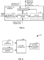
- FIG. 5 illustrates a functional block diagram of a finite element analysis (FEA) predictive modeler 50, stored on as computer executable instructions on computer readable medium, that is executable to predict the results of a therapeutic intervention on a patient's eye according to a finite element analysis (FEA) of the eye.
- FEA finite element analysis
- Each functional block illustrated in the diagram represents a series of executable instructions stored in the computer readable medium configured to perform the described function. It will be appreciated, however, that the various functional blocks can be configured to utilize functional instructions from an associated operating system or other common library sources in executing their associated functions.
- the illustrated FEA predictive modeler 50 receives data representing the eye of a given patient and constructs a model based on this data.
- a user can select a customized therapeutic intervention for the eye, represented as a series of therapeutic parameters. From the constructed model and the therapeutic parameters, a predicted shape of the eye, given the therapeutic intervention, can be determined. The predicted shape and at least one optical parameter calculated from the shape can be provided to the user at an associated display to illustrate the predicted surgical outcome to the user.
- the FEA predictive modeler 70 receives image data representing the patient's eye at a geometry generation element 72.
- image data can be provided directly from an imaging system, such a computer tomography (CT) system or a magnetic resonance imaging (MRI), or provided to the predictive modeler 70 as data stored on a computer readable medium.
- CT computer tomography
- MRI magnetic resonance imaging
- the geometry generation element 72 forms a three-dimensional representation of the patient's eye from the image data. For example, a two-dimensional image can be rotated to form a three-dimensional representation of the eye.
- the thicknesses of the various tissue layers can be provided as parameters from an associated database (not shown). Where the imaging modality allows for a three-dimensional image of the eye, the geometry can be determined directly from the image.
- the processed image data can be provided to a reconciliation engine 74 that establishes a finite element model of the ocular tissue according to the determined geometry of the eye and one or more biomechanical parameters for each of the tissue types.
- the biomechanical parameters for the cornea can include parameters such as Poisson's ratio and Young's modulus, as well as non-linear measures of elasticity, such as hysteresis, creep, stress relaxation, and a strain dependent function for Young's modulus, for each of the corneal tissue generally and for flap wounds in the cornea. These values can be taken from known average values for the appropriate tissue types or determined directly from the patient for one or more tissue types via measurement of the tissue properties under stress. It will be appreciated, however, in accordance with an aspect of the present invention, that where spatial variance of the biomechanical properties of the tissue from the average can be ascertained, individualized values can be used for the various finite element values within a given tissue type.
- selected elements can be altered by a user at a user interface 76 to represent a therapeutic intervention.
- a user can alter one or both of the thickness or biomechanical properties of the model for a given region of tissue as to simulate a therapeutic procedure, such as LASIK flaps or regions of cornea exposed to a collagen cross-linking agent.
- a set of standard therapeutic patterns can be provided as part of a pattern database (not shown) for application to the model, providing a user with a series of standard treatments as well as appropriate starting points for the user to design a custom treatment for the modeled eye.
- the model can be solved at the reconciliation engine 74 to provide a predicted geometry of the eye given the therapeutic intervention.
- the predicted geometry can be displayed to the user at the user interface 76.
- one or more parameters associated with the shape of the cornea in the determined geometry can be provided to an optical characterization component 78.
- the optical characterization component 78 calculates one or more properties of the eye, for example, as one or more optical power values and as a series of Zernike polynomials.
- a prediction of the refractive error and optical aberrations for a given patient's eye after a given therapeutic intervention can be determined, allowing the intervention to be customized for the patient.
- FIG. 6 illustrates a patient screening system 80 for determining if a patient is an appropriate candidate for a therapeutic procedure in accordance with one aspect of the present invention.
- the patient screening system 80 can be designed to predict patient outcomes as a plurality of outcome classes for one or more therapeutic interventions, including refractive surgery, collagen cross-linking, or intracorneal ring insertion.
- various elements of the illustrated patient screening system 80 can be implemented as computer programs, executable on one or more general purpose computers.
- any structures herein described can be implemented alternately as dedicated hardware circuitry for the described function or as a program code stored as part of a computer-assessable memory, such as a computer hard drive, random access memory, or a removable disk medium (e.g ., magnetic storage media, flash media, CD and DVD media, etc.).
- a computer-assessable memory such as a computer hard drive, random access memory, or a removable disk medium (e.g ., magnetic storage media, flash media, CD and DVD media, etc.).
- Functions carried out by the illustrated system but not helpful in understanding the claimed invention, are omitted from this diagram.
- a system implemented as a computer program would require some amount of working memory and routines for accessing this memory. Such matters are understood by those skilled in the art, and they are omitted in the interest of brevity.
- components of the patient screening system can be configured to interact with other software program modules.
- a pattern recognition classifier 82 can run within a computer operating system environment, utilizing data libraries available from the operating system.
- a given computer implemented element can receive data from one or more other program modules, and provide data to other program modules that utilize the system output.
- portions of the patient screening system 80 can reside on a remote computer system, whereby various system components and external resources can be linked via a computer network such as WAN, LAN, optical communication media, public switched telephone network, the global packet data communication network now commonly referred to as the Internet, any wireless network or any data transfer equipment offered by a service provider.
- the patient screening system 80 comprises a user interface 84 that can also allow the user to introduce one or more parameters of interest, such as the age, sex, medical history, and other medically relevant information concerning the patient.
- the patient screening system 80 can comprise an elastography imaging device 86 configured to provide strain and stress data relating to the eye of the patient.
- the elastography imaging device 86 can include an apparatus for applying a known perturbation (e.g ., force, pressure, energy, or displacement) to the eye tissue, for example, through applanation or localized variance of air pressure.
- An accompanying force sensor can be provided to measure the force applied by the elastography imaging device.
- the eye tissue can be imaged, with any appropriate imaging modality (e.g ., MRI or OCT), before and after the force is applied, or at a plurality of different forces, to provide a plurality of images of the eye. From these images, appropriate stress and strain data for the eye can be determined. Further, the elastography imaging device 86 can be utilized to determine a geometric profile of the eye. For the purpose of determining a geometry of the eye, the imaging device 86 can utilize magnetic resonance imaging (MRI), optical coherence tomography (OCT), Scheinpflug imaging, or any other appropriate imaging modality. The determined images can be supplemented by additional values, such as a measured corneal topography and a determined axial length of the eye.
- any appropriate imaging modality e.g MRI or OCT
- the elastography imaging device 32 can include, for example, an ultrasound imaging device or a partial coherence interferometer arrangement, for determining the axial length, as well as an appropriate imager for determining the corneal topography. It will be appreciated that, while the patient screening system 80, focuses on the effects of surgical and therapeutic intervention on the corneal and the resulting visual effects, the representation of the patient's eye can further include each of the sclera, the lens, the zonules, the choroid, the retina, the iris and, the ciliary body of the eye.
- Each of the user interface 84 and the elastography imaging device 86 can provide appropriate data to a feature extractor 90 that extracts feature data from the provided data.
- the feature extractor 90 extracts feature values from each image according to a set of selected features.
- the selected features can be any values derived from the pattern that vary sufficiently among the various output classes to serve as a basis for discriminating among them.
- Numerical data extracted from the features can be conceived for computational purposes as a feature vector, with each element of the vector representing a value derived from one feature within the pattern.
- Specific features can be selected by any reasonable method, but typically, appropriate features will be selected by experimentation and prior success.
- the feature extractor 90 can be configured to extract one or more parameters from data provided by the elastography imaging system 86.
- the image data provided by the elastography imaging component 86 can be digitized and processed to obtain an overall geometry of the eye.
- the images can be filtered and one or more edge detection algorithms can be utilized to determine the boundaries of the various tissue layers.
- the feature extractor 90 can provide measurements, such as the thicknesses of various tissue layers within the eye, as well as calculated values, such as Zernike polynomials for the cornea and optical power values (e.g., apical and tangential values). Further, in accordance with an aspect of the present invention, and as described above in FIG.
- the stress and strain values provided by the elastography imaging component 86 can be utilized to calculate one or more nonlinear measures of elasticity for the cornea at one or more locations.
- the measures can include hysteresis, creep, stress relaxation, and a strain dependent function for Young's modulus for any of a plurality of locations of interest within the eye, particularly the cornea and sclera.
- Each of the determined values can be included as part of the extracted feature vector, as well as any of a number of values derived from this information.
- a known displacement can be applied to the cornea in a first direction, and the displacement of the cornea in second and third directions, each perpendicular to the first direction and to one another, can be measured at a plurality of locations. For each location, a ratio of the measured displacement along the second direction to the known displacement along the first direction and a ratio of the measured displacement along the third direction to the known displacement along the first direction can be determined and provided as biomechanical parameters for the location
- corneal features extracted from the imaging, elastography and modeling can be a spatial variation of corneal elasticity, measured, for example, as a parametric or nonparametric measure of variation (e.g ., standard deviation) among a plurality of measured locations or as a gradient mapping of the cornea in one or more dimensions.
- a parametric or nonparametric measure of variation e.g ., standard deviation
- a difference in elasticity between sections subjected to collagen cross-linking or abnormal strains near the flap region after refractive procedure can be determined.
- Differences in biomechanical properties, including nonlinear viscoelasticty measures, from normal corneal tissue can also be determined for regions of residual stroma bed after a refractive surgery procedure.
- native heterogeneity within cornea is of interest during screening of patients, which can be measured, for example, as a measure of variation of one or more elasticity parameters or as a set of gradients determined from the measured values. For example, a maximum gradient or an average of a set of highest gradients can be utilized as a feature.
- Additional features can include features representing various regions of the cornea and sclera. For example, features representing elasticity measures and gradients from various regions of the cornea, for example, the anterior portion or posterior portion of the cornea, as well as derived values (e.g ., ratios and differences) intended to compare the properties of the two regions. Similar measures can be determined for a central portion of the cornea and a peripheral portion, and any other locations of interest for a given therapeutic procedure. Such regional features are of particular interest in detecting the onset of keratoconus, a known risk factor for refractive surgery, as regional and local abnormalities around stress/strain peaks can be detected. Accordingly, any of these derived parameters from the nonlinear elasticity data can be utilized as part of the feature vector, depending on the therapeutic intervention of interest for the patient screening system 80.
- the extracted feature vector is then provided to the pattern recognition classifier 82.
- the feature vector, representing the patient's data is, via an appropriate optimization algorithm, compared to training data representing each of a plurality of outcome classes.
- Any of a variety of optimization techniques can be utilized at the pattern recognition classifier for making this determination, including support vector machines, self-organized maps, fuzzy logic systems, data fusion processes, expert systems, rule, case based systems, or algorithmic programs, or any of a variety of neural network classifiers.
- Each outcome class represents a predicted range of outcomes for the patient given the application of the therapeutic procedure. This can range from a binary "good” and "bad” to a plurality of graduations of expected improvement.
- the training data represents feature vectors and associated outcomes for previous patients, although data from a whole-eye model could be utilized initially in training and testing the classifier model. From the provided feature vector, an outcome class is selected and a confidence in the selected result can be calculated. Results falling below a threshold confidence value can be rejected.
- FIG. 7 a methodology in accordance with various aspects of the present invention will be better appreciated with reference to FIG. 7 . While, for purposes of simplicity of explanation, the methodology of FIG. 7 are shown and described as executing serially, it is to be understood and appreciated that the present invention is not limited by the illustrated order, as some aspects could, in accordance with the present invention, occur in different orders and/or concurrently with other aspects from that shown and described herein. Moreover, not all illustrated features may be required to implement a methodology in accordance with an aspect of the present invention.
- FIG. 7 illustrates a methodology 100 for predicting the outcome of a surgical outcome in accordance with an aspect of the present invention.
- the methodology begins at step 102, where an eye of a patient is imaged by an imaging system.
- the imaging system can include a magnetic resonance imaging system (MRI), a computer tomography (CT) system, or any other appropriate image system for determining a geometry of the eye.
- the image generated by the imaging system can be two-dimensional or three-dimensional.
- the generated image is used to construct a representation of the geometry of the patient's eye.
- a two-dimensional image can be axially rotated to provide a representation of the patient's eye.
- Standard thickness values for various tissue layers can used to simulate a three-dimensional model. Where a three-dimensional imaging of the whole eye has been performed, the geometry of the patient's eye can be derived directly from the imaging data.
- the three-dimensional representation is divided into a plurality of finite elements, each represented by an associated function.
- Biomechanical parameters of the eye tissue are assigned to the associated functions of the plurality of finite elements to provide a finite element model of the eye.
- the associated functions reflect the behavior of a given portion of the tissue under stress and strain from other portions of the eye and intraocular pressure.
- the biomechanical parameters representing the eye tissue can be determined via direct measurement or known representative results for each tissue can be utilized.
- the finite element model is adjusted to account for intraocular pressure.
- distortions to the geometry of the eye caused by intraocular pressure can be determined, and a displacement of the corneal tissue can be added to the model to simulate an eye that is not distorted by intraocular pressure.
- the actual intraocular pressure and an elasticity of the cornea can be measured, and an appropriate adjustment can be applied, for example, from a table of known corneal deflections for given values of intraocular pressure.
- a user provides an alteration to the model that simulates the effects of a therapeutic procedure.
- an appropriate pattern of changes to the geometry and biomechanical properties of the model can be selected at a graphical user interface to simulate one of a variety of refractive surgical procedures, an application of a collagen cross-linking treatment, or any other appropriate therapeutic intervention.
- the patterns can be customizable, allowing a user to customize a therapeutic procedure to produce optimal results.
- the finite element model is reconciled to incorporate the changes provided by the user to provide a predicted shape of the eye.
- the predicted shape is adjusted to reflect the presence of an appropriate amount of intraocular pressure. For example, a deflection to the cornea can be applied according to a measured corneal stiffness and intraocular pressure of the patient.
- at least one optical parameter can be calculated at step 116.
- the predicted corneal shape can be characterized as a series of Zernike polynomials, and one or more optical power values can be calculated from the predicted shape.
- the predicted shape and the calculated optical parameters are displayed to a user.
- FIG. 8 illustrates a computer system 200 that can be employed to implement systems and methods described herein, such as based on computer executable instructions running on the computer system.
- the computer system 200 can be implemented on one or more general purpose networked computer systems, embedded computer systems, routers, switches, server devices, client devices, various intermediate devices/nodes and/or stand alone computer systems. Additionally, the computer system 200 can be implemented as part of the computer-aided engineering (CAE) tool running computer executable instructions to perform a method as described herein.
- CAE computer-aided engineering
- the computer system 200 includes a processor 202 and a system memory 204. Dual microprocessors and other multi-processor architectures can also be utilized as the processor 202.
- the processor 202 and system memory 204 can be coupled by any of several types of bus structures, including a memory bus or memory controller, a peripheral bus, and a local bus using any of a variety of bus architectures.
- the system memory 204 includes read only memory (ROM) 208 and random access memory (RAM) 210.
- ROM read only memory
- RAM random access memory
- a basic input/output system (BIOS) can reside in the ROM 208, generally containing the basic routines that help to transfer information between elements within the computer system 200, such as a reset or power-up.
- the computer system 200 can include one or more types of long-term data storage 214, including a hard disk drive, a magnetic disk drive, ( e.g., to read from or write to a removable disk), and an optical disk drive, ( e.g., for reading a CD-ROM or DVD disk or to read from or write to other optical media).
- the long-term data storage can be connected to the processor 202 by a drive interface 216.
- the long-term storage components 214 provide nonvolatile storage of data, data structures, and computer-executable instructions for the computer system 200.
- a number of program modules may also be stored in one or more of the drives as well as in the RAM 210, including an operating system, one or more application programs, other program modules, and program data.
- a user may enter commands and information into the computer system 200 through one or more input devices 220, such as a keyboard or a pointing device (e.g., a mouse). These and other input devices are often connected to the processor 202 through a device interface 222.
- the input devices can be connected to the system bus by one or several parallel ports, a serial port or a universal serial bus (USB).
- One or more output device(s) 224 such as a visual display device or printer, can also be connected to the processor 202 via the device interface 222.
- the computer system 200 may operate in a networked environment using logical connections (e.g ., a local area network (LAN) or wide area network (WAN) to one or more remote computers 230.
- a given remote computer 230 may be a workstation, a computer system, a router, a peer device or other common network node, and typically includes many or all of the elements described relative to the computer system 200.
- the computer system 200 can communicate with the remote computers 230 via a network interface 232, such as a wired or wireless network interface card or modem.
- application programs and program data depicted relative to the computer system 200, or portions thereof, may be stored in memory associated with the remote computers 230.
Landscapes
- Engineering & Computer Science (AREA)
- Health & Medical Sciences (AREA)
- Medical Informatics (AREA)
- Physics & Mathematics (AREA)
- Theoretical Computer Science (AREA)
- General Health & Medical Sciences (AREA)
- Life Sciences & Earth Sciences (AREA)
- Bioinformatics & Cheminformatics (AREA)
- Public Health (AREA)
- Data Mining & Analysis (AREA)
- Physiology (AREA)
- Biomedical Technology (AREA)
- Biotechnology (AREA)
- Spectroscopy & Molecular Physics (AREA)
- Bioinformatics & Computational Biology (AREA)
- Primary Health Care (AREA)
- Evolutionary Biology (AREA)
- Molecular Biology (AREA)
- Epidemiology (AREA)
- Biophysics (AREA)
- Pathology (AREA)
- Databases & Information Systems (AREA)
- Computational Linguistics (AREA)
- Software Systems (AREA)
- Mathematical Physics (AREA)
- General Physics & Mathematics (AREA)
- General Engineering & Computer Science (AREA)
- Computing Systems (AREA)
- Evolutionary Computation (AREA)
- Artificial Intelligence (AREA)
- Eye Examination Apparatus (AREA)
Claims (9)
- System zum Vorhersagen der Ergebnisse einer therapeutischen Intervention für ein Auge eines Patienten, Folgendes umfassend:ein Bildgebungssystem, konfiguriert zum Bereitstellen von Bilddaten, die mindestens einen Teil des Auges des Patienten repräsentieren;eine Eingabevorrichtung, dazu konfiguriert, einem Benutzer zu ermöglichen, eine vorgeschlagene therapeutische Intervention für das Auge des Patienten zu entwickeln, wobei die vorgeschlagene therapeutische Intervention eine vorgeschlagene Veränderung von mindestens einer biomechanischen Eigenschaft für einen Teil des Gewebes umfasst, aus dem das Auge des Patienten besteht, um eine Veränderung in den Materialeigenschaften des Teils des Gewebes zu stimulieren;eine finite Elementmodellierungskomponente, dazu konfiguriert, ein finites Elementmodell zu erzeugen, das den Zustand des Auges des Patienten nach der vorgeschlagenen therapeutischen Intervention gemäß den Bilddaten repräsentiert, wobei die mindestens eine biomechanische Eigenschaft des Gewebes, aus dem das Auge besteht, und die Veränderung von mindestens einer biomechanischen Eigenschaft des Teils des Gewebes, das durch die vorgeschlagene therapeutische Intervention repräsentiert ist, wobei das erzeugte Modell keine apriorischen Beschränkungen der Bewegung eines Hornhautrandes des Auges hat, wobei die finite Elementmodellierungskomponente, konfiguriert zum Anwenden der Veränderung auf die mindestens eine biomechanische Eigenschaft des Teils des Gewebes, repräsentiert durch die vorgeschlagene therapeutische Intervention an einem inversen Modell, das dazu angepasst wird, den Zustand des Auges des Patienten bei fehlendem intraokularem Druck zu reflektieren und das erzeugte finite Elementmodell anzupassen, um einen geeigneten Wert für den Patienten für intraokularen Druck einzuschließen; undein Display, dazu konfiguriert, das erzeugte Modell dem Benutzer anzuzeigen.
- System nach Anspruch 1, wobei die finite Elementmodellierungskomponente dazu konfiguriert ist, ein finites Elementmodell gemäß mindestens einer biomechanischen Eigenschaft eines jeden von Folgenden zu erzeugen: Korneagewebe, Skleragewebe und mindestens eine andere Struktur des Auges.
- System nach Anspruch 1, wobei die vorgeschlagene therapeutische Intervention eine vorgeschlagene Veränderung der Bilddaten umfasst, um eine Veränderung der bestimmten Geometrie des Auges zu simulieren.
- System nach Anspruch 1, außerdem eine Parametermessvorrichtung umfassend, dazu konfiguriert, die mindestens eine biomechanische Eigenschaft des Gewebes zu bestimmen, aus dem das Auge des Patienten besteht und das für den Patienten spezifisch ist.
- System nach Anspruch 4, wobei die Parametermessvorrichtung Folgendes umfasst:eine Elastographie-Bildgebungsvorrichtung, konfiguriert zum Anwenden einer bekannten Perturbation auf mindestens einen Teil des Augengewebes und zum Messen einer Verlagerung des Augengewebes als Reaktion auf die Kraft auf einer Vielzahl von Stellen; undeinen Datenprozessor, dazu konfiguriert, die mindestens eine biomechanische Eigenschaft des Auges zu bestimmen, die für den Patienten gemäß der gemessenen Verlagerung und der bekannten Perturbation spezifisch ist.
- System nach Anspruch 5, wobei die Elastographie-Bildgebungsvorrichtung dazu konfiguriert ist, eines von einer akustischen Perturbation und einer pneumatischen Perturbation auf das Augengewebe anzuwenden.
- System nach Anspruch 1, wobei die mindestens eine biomechanische Eigenschaft eine gemessene viscoelastische Hysterese des Augengewebes einschließt.
- System nach Anspruch 1, wobei mindestens eine biomechanische Eigenschaft eine Stressrelaxations-Eigenschaft für das Augengewebe einschließt.
- System nach Anspruch 1, wobei die finite Elementmodellierungskomponente eine optische Charakterisationskomponente umfasst, dazu konfiguriert, mindestens einen optischen Parameter aus einer vorhergesagten Geometrie zu kalkulieren, die von dem finiten Elementmodell abgeleitet ist.
Applications Claiming Priority (2)
| Application Number | Priority Date | Filing Date | Title |
|---|---|---|---|
| US4717908P | 2008-04-23 | 2008-04-23 | |
| PCT/US2009/041584 WO2009132221A1 (en) | 2008-04-23 | 2009-04-23 | Method for modeling biomechanical properties of an eye |
Publications (2)
| Publication Number | Publication Date |
|---|---|
| EP2297661A1 EP2297661A1 (de) | 2011-03-23 |
| EP2297661B1 true EP2297661B1 (de) | 2018-06-13 |
Family
ID=40765775
Family Applications (1)
| Application Number | Title | Priority Date | Filing Date |
|---|---|---|---|
| EP09735500.2A Active EP2297661B1 (de) | 2008-04-23 | 2009-04-23 | Verfahren zum modellieren biomechanischer eigenschaften eines auges |
Country Status (4)
| Country | Link |
|---|---|
| US (2) | US8346518B2 (de) |
| EP (1) | EP2297661B1 (de) |
| ES (1) | ES2686090T3 (de) |
| WO (1) | WO2009132221A1 (de) |
Families Citing this family (42)
| Publication number | Priority date | Publication date | Assignee | Title |
|---|---|---|---|---|
| US20100049447A1 (en) * | 2008-08-22 | 2010-02-25 | Gholam Peyman | Method of modeling the behavior of an eye subjected to an external force |
| US8646916B2 (en) * | 2009-03-04 | 2014-02-11 | Perfect Ip, Llc | System for characterizing a cornea and obtaining an opthalmic lens |
| WO2011050164A1 (en) | 2009-10-21 | 2011-04-28 | Avedro, Inc. | Eye therapy |
| JP6377906B2 (ja) | 2010-03-19 | 2018-08-22 | アヴェドロ・インコーポレーテッドAvedro,Inc. | 眼治療を適用およびモニターするためのシステム |
| US9320430B2 (en) * | 2010-03-31 | 2016-04-26 | Reichert, Inc. | Ophthalmic diagnostic instrument and method |
| US9443343B2 (en) * | 2010-11-24 | 2016-09-13 | Samsung Electronics Co., Ltd. | Method and apparatus for realistically reproducing eyeball |
| WO2012118962A2 (en) | 2011-03-02 | 2012-09-07 | University Of Pittsburgh - Of The Commonwealth System Of Higher Education | Optical coherence tomography as a rapid, accurate, non-contact method of visualizing the palisades of vogt |
| WO2012162529A1 (en) | 2011-05-24 | 2012-11-29 | Avedro, Inc. | Systems and methods for reshaping an eye feature |
| WO2012167260A2 (en) | 2011-06-02 | 2012-12-06 | Avedro, Inc. | Systems and methods for monitoring time based photo active agent delivery or photo active marker presence |
| EP2760397A4 (de) * | 2011-10-02 | 2015-06-24 | Avedro Inc | System und verfahren zur anwendung und überwachung einer augentherapie |
| WO2013106385A2 (en) * | 2012-01-09 | 2013-07-18 | The Trustees Of Columbia University In The City Of New York | System and methods for determining tissue elasticity |
| EP2872081B2 (de) | 2012-07-16 | 2025-07-16 | Avedro, Inc. | Systeme zur hornhautvernetzung mit gepulstem licht |
| US10398763B2 (en) | 2013-01-28 | 2019-09-03 | The Cleveland Clinic Foundation | Corneal stiffening for treating astigmatism |
| ES2836851T3 (es) | 2013-03-15 | 2021-06-28 | Annmarie Hipsley | Sistemas para afectar las propiedades biomecánicas del tejido conectivo |
| US9498114B2 (en) | 2013-06-18 | 2016-11-22 | Avedro, Inc. | Systems and methods for determining biomechanical properties of the eye for applying treatment |
| US9498122B2 (en) | 2013-06-18 | 2016-11-22 | Avedro, Inc. | Systems and methods for determining biomechanical properties of the eye for applying treatment |
| WO2015123492A2 (en) * | 2014-02-13 | 2015-08-20 | The Cleveland Clinic Foundation | Predicting and mitigating risk of ectasia and optimizing therapeutic outcomes |
| US9854964B2 (en) | 2014-04-30 | 2018-01-02 | The Cleveland Clinic Foundation | Measurement of biomechanical properties in an OCT image |
| KR102545628B1 (ko) | 2014-10-27 | 2023-06-20 | 아베드로 인코퍼레이티드 | 눈의 교차-결합 처리를 위한 시스템 및 방법 |
| WO2016077747A1 (en) | 2014-11-13 | 2016-05-19 | Avedro, Inc. | Multipass virtually imaged phased array etalon |
| ES2571209B1 (es) * | 2014-11-21 | 2016-12-30 | Alicante Oftalmológica S.L | Sistema de caracterización 3D de la respuesta mecánica del tejido de la córnea y procedimiento de medida con dicho sistema |
| TWI569224B (zh) * | 2015-02-17 | 2017-02-01 | 國立臺灣大學 | 眼角膜楊氏模數演算方法及使用其之量測系統 |
| EP3285704B1 (de) | 2015-04-24 | 2020-11-18 | Avedro Inc. | Systeme zur lichtaktivierung eines an einem auge applizierten lichtsensibilisators |
| US10028657B2 (en) | 2015-05-22 | 2018-07-24 | Avedro, Inc. | Systems and methods for monitoring cross-linking activity for corneal treatments |
| KR102706856B1 (ko) | 2015-07-21 | 2024-09-19 | 아베드로 인코퍼레이티드 | 광증감제로 눈을 치료하기 위한 시스템 및 방법 |
| US20190192115A1 (en) | 2016-05-08 | 2019-06-27 | The Cleveland Clinic Foundation | Measurement of biomechanical properties of tissue |
| US11071450B2 (en) | 2016-06-29 | 2021-07-27 | Ace Vision Group, Inc. | System and methods using real-time predictive virtual 3D eye finite element modeling for simulation of ocular structure biomechanics |
| US12350198B2 (en) | 2016-09-28 | 2025-07-08 | Lensar, Inc. | Systems for laser eye surgery |
| US10426551B2 (en) * | 2016-12-09 | 2019-10-01 | Microsoft Technology Licensing, Llc | Personalized refractive surgery recommendations for eye patients |
| JP7035081B2 (ja) | 2017-01-11 | 2022-03-14 | アヴェドロ・インコーポレーテッド | 角膜におけるクロスリンキング分布及び/又は角膜の構造的特徴を決定するためのシステム及び方法 |
| CN108346472A (zh) * | 2017-01-24 | 2018-07-31 | 阿格斯医材公司 | 眼角膜手术风险评估方法及其系统 |
| CA3055996A1 (en) * | 2017-03-13 | 2018-09-20 | Kejako Sa | Accommodative lens device |
| US12465436B2 (en) * | 2018-10-19 | 2025-11-11 | Lensar, Inc. | Cloud based system cataract treatment database and algorithm system |
| CN109965841B (zh) * | 2019-04-23 | 2024-07-02 | 广东唯仁医疗科技有限公司 | 一种人工晶体植入术的弹性分析装置及方法 |
| US11751953B2 (en) * | 2019-05-03 | 2023-09-12 | Lensar, Inc. | Cloud based system cataract treatment database and algorithm system |
| JP2023509439A (ja) | 2020-01-03 | 2023-03-08 | レンサー インク | 複合レーザー-超音波水晶体乳化吸引治療のための統合システム |
| CN111820862B (zh) * | 2020-07-10 | 2023-07-21 | 温州医科大学 | 一种基于oct图像建模引导的个性化巩膜镜适配性评估方法和设计方法 |
| KR20220132874A (ko) * | 2021-03-24 | 2022-10-04 | 한국전자통신연구원 | 신경 근골격 모델 기반 건강 관리 장치 및 건강 관리 서비스 제공 방법 |
| CN114943707B (zh) * | 2022-05-26 | 2023-06-30 | 天津市眼科医院 | 基于像素级角膜生物力学参数的细微角膜形变识别方法及装置 |
| CN115381623B (zh) * | 2022-07-19 | 2025-01-17 | 温州医科大学附属眼视光医院 | 一种个性化的角膜交联系统及其角膜中间结果处理方法 |
| US12279819B1 (en) * | 2024-09-27 | 2025-04-22 | Virtualens Llc | Vision correction simulation system and methods of use |
| CN119830680B (zh) * | 2025-03-14 | 2025-05-09 | 深圳市新产业眼科新技术有限公司 | 人工晶状体的设计优化方法及系统 |
Family Cites Families (10)
| Publication number | Priority date | Publication date | Assignee | Title |
|---|---|---|---|---|
| US5891131A (en) * | 1993-02-01 | 1999-04-06 | Arizona Board Of Regents | Method and apparatus for automated simulation and design of corneal refractive procedures |
| US6302540B1 (en) * | 1999-03-04 | 2001-10-16 | Shamir Optical Industries | Method for the design of multifocal optical elements |
| US20020077797A1 (en) * | 2000-12-18 | 2002-06-20 | Hall Gary W. | Method and apparatus for automated simulation and design of corneal refractive procedures |
| US6755524B2 (en) * | 2001-12-12 | 2004-06-29 | Inray Ltd. | Ophthalmic optical elements and methods for the design thereof |
| US7130835B2 (en) * | 2002-03-28 | 2006-10-31 | Bausch & Lomb Incorporated | System and method for predictive ophthalmic correction |
| EP1567907A4 (de) * | 2002-12-06 | 2009-09-02 | Amo Mfg Usa Llc | Presbyopikorrektur durch verwendung von patientendaten |
| US7004902B2 (en) * | 2003-03-21 | 2006-02-28 | Reichert, Inc. | Method and apparatus for measuring biomechanical characteristics of corneal tissue |
| US20070121067A1 (en) * | 2005-11-26 | 2007-05-31 | Davis Andrew P | Intraocular pressure and biomechanical properties measurement device and method |
| CA2653309C (en) * | 2006-05-26 | 2013-11-19 | The Cleveland Clinic Foundation | Method for measuring biomechanical properties in an eye |
| US8070679B2 (en) * | 2007-07-23 | 2011-12-06 | The Board Of Trustees Of The University Of Illinois | Accurate determination of intraocular pressure and characterization of mechanical properties of the cornea |
-
2009
- 2009-04-23 EP EP09735500.2A patent/EP2297661B1/de active Active
- 2009-04-23 US US12/429,149 patent/US8346518B2/en active Active
- 2009-04-23 WO PCT/US2009/041584 patent/WO2009132221A1/en not_active Ceased
- 2009-04-23 ES ES09735500.2T patent/ES2686090T3/es active Active
-
2012
- 2012-12-31 US US13/731,255 patent/US8812280B2/en active Active
Non-Patent Citations (1)
| Title |
|---|
| None * |
Also Published As
| Publication number | Publication date |
|---|---|
| US8346518B2 (en) | 2013-01-01 |
| US20130138400A1 (en) | 2013-05-30 |
| US8812280B2 (en) | 2014-08-19 |
| ES2686090T3 (es) | 2018-10-16 |
| EP2297661A1 (de) | 2011-03-23 |
| US20090271155A1 (en) | 2009-10-29 |
| WO2009132221A1 (en) | 2009-10-29 |
Similar Documents
| Publication | Publication Date | Title |
|---|---|---|
| EP2297661B1 (de) | Verfahren zum modellieren biomechanischer eigenschaften eines auges | |
| US10141075B2 (en) | Predicting and mitigating risk of ectasia and optimizing therapeutic outcomes | |
| Simonini et al. | Customized finite element modelling of the human cornea | |
| Ariza-Gracia et al. | Automatized patient-specific methodology for numerical determination of biomechanical corneal response | |
| Ariza-Gracia et al. | Coupled biomechanical response of the cornea assessed by non-contact tonometry. A simulation study | |
| Pandolfi | Cornea modelling | |
| US8070679B2 (en) | Accurate determination of intraocular pressure and characterization of mechanical properties of the cornea | |
| Elsheikh | Finite element modeling of corneal biomechanical behavior | |
| Rahmati et al. | Biomechanics of the keratoconic cornea: Theory, segmentation, pressure distribution, and coupled FE-optimization algorithm | |
| US20230037772A1 (en) | Method for determining lens and apparatus using the method | |
| Han et al. | Biomechanical and refractive behaviors of keratoconic cornea based on three-dimensional anisotropic hyperelastic models | |
| US8562530B2 (en) | System and method for assessing risk of glaucoma onset | |
| Pant et al. | Appropriate objective functions for quantifying iris mechanical properties using inverse finite element modeling | |
| Asher et al. | Etiology of Keratoconus: proposed biomechanical pathogenesis | |
| US7987077B2 (en) | System and method for simulating an LIOB protocol to establish a treatment plan for a patient | |
| CN117253621B (zh) | 角膜塑形效果预估方法、装置、计算机设备和存储介质 | |
| WO2016111646A1 (en) | In vivo corneal modeling | |
| Śródka et al. | Optically inspired biomechanical model of the human eyeball | |
| Lou et al. | Corneal stiffness mapping that accounts for anisotropic properties of corneal tissue | |
| Ariza-Gracia et al. | Personalized corneal biomechanics | |
| CN119940045B (zh) | 一种基于生物力学的个性化巩膜镜智能验配系统及其应用方法 | |
| Xu | Investigation of corneal biomechanical and optical behaviors by developing individualized finite element model | |
| Velázquez et al. | Comparison of corneal morphologic parameters and high order aberrations in keratoconus and normal eyes | |
| Zahabi et al. | A 3D finite element model quantifying viscoelastic boundary condition and simulation of effects on ocular deformation and optical geometry. | |
| Zakharov et al. | Modeling Biomechanics of the Corneal Column with Keratoconus During Implantation of Intrastromal Segments |
Legal Events
| Date | Code | Title | Description |
|---|---|---|---|
| PUAI | Public reference made under article 153(3) epc to a published international application that has entered the european phase |
Free format text: ORIGINAL CODE: 0009012 |
|
| 17P | Request for examination filed |
Effective date: 20101119 |
|
| AK | Designated contracting states |
Kind code of ref document: A1 Designated state(s): AT BE BG CH CY CZ DE DK EE ES FI FR GB GR HR HU IE IS IT LI LT LU LV MC MK MT NL NO PL PT RO SE SI SK TR |
|
| AX | Request for extension of the european patent |
Extension state: AL BA RS |
|
| RIN1 | Information on inventor provided before grant (corrected) |
Inventor name: ROY, ABHIJIT, SINHA Inventor name: DUPPS, WILLIAM, J., JR. |
|
| DAX | Request for extension of the european patent (deleted) | ||
| 17Q | First examination report despatched |
Effective date: 20130610 |
|
| STAA | Information on the status of an ep patent application or granted ep patent |
Free format text: STATUS: EXAMINATION IS IN PROGRESS |
|
| GRAP | Despatch of communication of intention to grant a patent |
Free format text: ORIGINAL CODE: EPIDOSNIGR1 |
|
| STAA | Information on the status of an ep patent application or granted ep patent |
Free format text: STATUS: GRANT OF PATENT IS INTENDED |
|
| INTG | Intention to grant announced |
Effective date: 20180105 |
|
| GRAS | Grant fee paid |
Free format text: ORIGINAL CODE: EPIDOSNIGR3 |
|
| GRAA | (expected) grant |
Free format text: ORIGINAL CODE: 0009210 |
|
| STAA | Information on the status of an ep patent application or granted ep patent |
Free format text: STATUS: THE PATENT HAS BEEN GRANTED |
|
| AK | Designated contracting states |
Kind code of ref document: B1 Designated state(s): AT BE BG CH CY CZ DE DK EE ES FI FR GB GR HR HU IE IS IT LI LT LU LV MC MK MT NL NO PL PT RO SE SI SK TR |
|
| REG | Reference to a national code |
Ref country code: GB Ref legal event code: FG4D |
|
| REG | Reference to a national code |
Ref country code: CH Ref legal event code: EP Ref country code: AT Ref legal event code: REF Ref document number: 1009197 Country of ref document: AT Kind code of ref document: T Effective date: 20180615 |
|
| REG | Reference to a national code |
Ref country code: IE Ref legal event code: FG4D |
|
| REG | Reference to a national code |
Ref country code: DE Ref legal event code: R096 Ref document number: 602009052756 Country of ref document: DE |
|
| REG | Reference to a national code |
Ref country code: ES Ref legal event code: FG2A Ref document number: 2686090 Country of ref document: ES Kind code of ref document: T3 Effective date: 20181016 |
|
| REG | Reference to a national code |
Ref country code: NL Ref legal event code: MP Effective date: 20180613 |
|
| REG | Reference to a national code |
Ref country code: LT Ref legal event code: MG4D |
|
| PG25 | Lapsed in a contracting state [announced via postgrant information from national office to epo] |
Ref country code: SE Free format text: LAPSE BECAUSE OF FAILURE TO SUBMIT A TRANSLATION OF THE DESCRIPTION OR TO PAY THE FEE WITHIN THE PRESCRIBED TIME-LIMIT Effective date: 20180613 Ref country code: LT Free format text: LAPSE BECAUSE OF FAILURE TO SUBMIT A TRANSLATION OF THE DESCRIPTION OR TO PAY THE FEE WITHIN THE PRESCRIBED TIME-LIMIT Effective date: 20180613 Ref country code: FI Free format text: LAPSE BECAUSE OF FAILURE TO SUBMIT A TRANSLATION OF THE DESCRIPTION OR TO PAY THE FEE WITHIN THE PRESCRIBED TIME-LIMIT Effective date: 20180613 Ref country code: CY Free format text: LAPSE BECAUSE OF FAILURE TO SUBMIT A TRANSLATION OF THE DESCRIPTION OR TO PAY THE FEE WITHIN THE PRESCRIBED TIME-LIMIT Effective date: 20180613 Ref country code: NO Free format text: LAPSE BECAUSE OF FAILURE TO SUBMIT A TRANSLATION OF THE DESCRIPTION OR TO PAY THE FEE WITHIN THE PRESCRIBED TIME-LIMIT Effective date: 20180913 Ref country code: BG Free format text: LAPSE BECAUSE OF FAILURE TO SUBMIT A TRANSLATION OF THE DESCRIPTION OR TO PAY THE FEE WITHIN THE PRESCRIBED TIME-LIMIT Effective date: 20180913 |
|
| REG | Reference to a national code |
Ref country code: DE Ref legal event code: R079 Ref document number: 602009052756 Country of ref document: DE Free format text: PREVIOUS MAIN CLASS: G06F0019000000 Ipc: G16Z0099000000 |
|
| PG25 | Lapsed in a contracting state [announced via postgrant information from national office to epo] |
Ref country code: GR Free format text: LAPSE BECAUSE OF FAILURE TO SUBMIT A TRANSLATION OF THE DESCRIPTION OR TO PAY THE FEE WITHIN THE PRESCRIBED TIME-LIMIT Effective date: 20180914 Ref country code: LV Free format text: LAPSE BECAUSE OF FAILURE TO SUBMIT A TRANSLATION OF THE DESCRIPTION OR TO PAY THE FEE WITHIN THE PRESCRIBED TIME-LIMIT Effective date: 20180613 Ref country code: HR Free format text: LAPSE BECAUSE OF FAILURE TO SUBMIT A TRANSLATION OF THE DESCRIPTION OR TO PAY THE FEE WITHIN THE PRESCRIBED TIME-LIMIT Effective date: 20180613 |
|
| REG | Reference to a national code |
Ref country code: AT Ref legal event code: MK05 Ref document number: 1009197 Country of ref document: AT Kind code of ref document: T Effective date: 20180613 |
|
| PG25 | Lapsed in a contracting state [announced via postgrant information from national office to epo] |
Ref country code: NL Free format text: LAPSE BECAUSE OF FAILURE TO SUBMIT A TRANSLATION OF THE DESCRIPTION OR TO PAY THE FEE WITHIN THE PRESCRIBED TIME-LIMIT Effective date: 20180613 |
|
| PG25 | Lapsed in a contracting state [announced via postgrant information from national office to epo] |
Ref country code: CZ Free format text: LAPSE BECAUSE OF FAILURE TO SUBMIT A TRANSLATION OF THE DESCRIPTION OR TO PAY THE FEE WITHIN THE PRESCRIBED TIME-LIMIT Effective date: 20180613 Ref country code: SK Free format text: LAPSE BECAUSE OF FAILURE TO SUBMIT A TRANSLATION OF THE DESCRIPTION OR TO PAY THE FEE WITHIN THE PRESCRIBED TIME-LIMIT Effective date: 20180613 Ref country code: IS Free format text: LAPSE BECAUSE OF FAILURE TO SUBMIT A TRANSLATION OF THE DESCRIPTION OR TO PAY THE FEE WITHIN THE PRESCRIBED TIME-LIMIT Effective date: 20181013 Ref country code: AT Free format text: LAPSE BECAUSE OF FAILURE TO SUBMIT A TRANSLATION OF THE DESCRIPTION OR TO PAY THE FEE WITHIN THE PRESCRIBED TIME-LIMIT Effective date: 20180613 Ref country code: EE Free format text: LAPSE BECAUSE OF FAILURE TO SUBMIT A TRANSLATION OF THE DESCRIPTION OR TO PAY THE FEE WITHIN THE PRESCRIBED TIME-LIMIT Effective date: 20180613 Ref country code: PL Free format text: LAPSE BECAUSE OF FAILURE TO SUBMIT A TRANSLATION OF THE DESCRIPTION OR TO PAY THE FEE WITHIN THE PRESCRIBED TIME-LIMIT Effective date: 20180613 Ref country code: RO Free format text: LAPSE BECAUSE OF FAILURE TO SUBMIT A TRANSLATION OF THE DESCRIPTION OR TO PAY THE FEE WITHIN THE PRESCRIBED TIME-LIMIT Effective date: 20180613 |
|
| REG | Reference to a national code |
Ref country code: DE Ref legal event code: R097 Ref document number: 602009052756 Country of ref document: DE |
|
| PLBE | No opposition filed within time limit |
Free format text: ORIGINAL CODE: 0009261 |
|
| STAA | Information on the status of an ep patent application or granted ep patent |
Free format text: STATUS: NO OPPOSITION FILED WITHIN TIME LIMIT |
|
| 26N | No opposition filed |
Effective date: 20190314 |
|
| PG25 | Lapsed in a contracting state [announced via postgrant information from national office to epo] |
Ref country code: DK Free format text: LAPSE BECAUSE OF FAILURE TO SUBMIT A TRANSLATION OF THE DESCRIPTION OR TO PAY THE FEE WITHIN THE PRESCRIBED TIME-LIMIT Effective date: 20180613 Ref country code: SI Free format text: LAPSE BECAUSE OF FAILURE TO SUBMIT A TRANSLATION OF THE DESCRIPTION OR TO PAY THE FEE WITHIN THE PRESCRIBED TIME-LIMIT Effective date: 20180613 |
|
| REG | Reference to a national code |
Ref country code: CH Ref legal event code: PL |
|
| REG | Reference to a national code |
Ref country code: BE Ref legal event code: MM Effective date: 20190430 |
|
| PG25 | Lapsed in a contracting state [announced via postgrant information from national office to epo] |
Ref country code: LU Free format text: LAPSE BECAUSE OF NON-PAYMENT OF DUE FEES Effective date: 20190423 Ref country code: MC Free format text: LAPSE BECAUSE OF FAILURE TO SUBMIT A TRANSLATION OF THE DESCRIPTION OR TO PAY THE FEE WITHIN THE PRESCRIBED TIME-LIMIT Effective date: 20180613 |
|
| PG25 | Lapsed in a contracting state [announced via postgrant information from national office to epo] |
Ref country code: CH Free format text: LAPSE BECAUSE OF NON-PAYMENT OF DUE FEES Effective date: 20190430 Ref country code: LI Free format text: LAPSE BECAUSE OF NON-PAYMENT OF DUE FEES Effective date: 20190430 |
|
| PG25 | Lapsed in a contracting state [announced via postgrant information from national office to epo] |
Ref country code: BE Free format text: LAPSE BECAUSE OF NON-PAYMENT OF DUE FEES Effective date: 20190430 |
|
| PG25 | Lapsed in a contracting state [announced via postgrant information from national office to epo] |
Ref country code: TR Free format text: LAPSE BECAUSE OF FAILURE TO SUBMIT A TRANSLATION OF THE DESCRIPTION OR TO PAY THE FEE WITHIN THE PRESCRIBED TIME-LIMIT Effective date: 20180613 |
|
| PG25 | Lapsed in a contracting state [announced via postgrant information from national office to epo] |
Ref country code: IE Free format text: LAPSE BECAUSE OF NON-PAYMENT OF DUE FEES Effective date: 20190423 |
|
| PG25 | Lapsed in a contracting state [announced via postgrant information from national office to epo] |
Ref country code: PT Free format text: LAPSE BECAUSE OF FAILURE TO SUBMIT A TRANSLATION OF THE DESCRIPTION OR TO PAY THE FEE WITHIN THE PRESCRIBED TIME-LIMIT Effective date: 20181015 |
|
| PG25 | Lapsed in a contracting state [announced via postgrant information from national office to epo] |
Ref country code: MT Free format text: LAPSE BECAUSE OF FAILURE TO SUBMIT A TRANSLATION OF THE DESCRIPTION OR TO PAY THE FEE WITHIN THE PRESCRIBED TIME-LIMIT Effective date: 20180613 Ref country code: HU Free format text: LAPSE BECAUSE OF FAILURE TO SUBMIT A TRANSLATION OF THE DESCRIPTION OR TO PAY THE FEE WITHIN THE PRESCRIBED TIME-LIMIT; INVALID AB INITIO Effective date: 20090423 |
|
| PG25 | Lapsed in a contracting state [announced via postgrant information from national office to epo] |
Ref country code: MK Free format text: LAPSE BECAUSE OF FAILURE TO SUBMIT A TRANSLATION OF THE DESCRIPTION OR TO PAY THE FEE WITHIN THE PRESCRIBED TIME-LIMIT Effective date: 20180613 |
|
| P01 | Opt-out of the competence of the unified patent court (upc) registered |
Effective date: 20230531 |
|
| PGFP | Annual fee paid to national office [announced via postgrant information from national office to epo] |
Ref country code: DE Payment date: 20250417 Year of fee payment: 17 |
|
| PGFP | Annual fee paid to national office [announced via postgrant information from national office to epo] |
Ref country code: GB Payment date: 20250417 Year of fee payment: 17 Ref country code: ES Payment date: 20250519 Year of fee payment: 17 |
|
| PGFP | Annual fee paid to national office [announced via postgrant information from national office to epo] |
Ref country code: IT Payment date: 20250430 Year of fee payment: 17 |
|
| PGFP | Annual fee paid to national office [announced via postgrant information from national office to epo] |
Ref country code: FR Payment date: 20250422 Year of fee payment: 17 |