EP2297498B1 - Ventil mit hoher mittlerer betriebsdauer - Google Patents
Ventil mit hoher mittlerer betriebsdauer Download PDFInfo
- Publication number
- EP2297498B1 EP2297498B1 EP09776972.3A EP09776972A EP2297498B1 EP 2297498 B1 EP2297498 B1 EP 2297498B1 EP 09776972 A EP09776972 A EP 09776972A EP 2297498 B1 EP2297498 B1 EP 2297498B1
- Authority
- EP
- European Patent Office
- Prior art keywords
- valve
- seal
- sealing
- valve body
- metal
- Prior art date
- Legal status (The legal status is an assumption and is not a legal conclusion. Google has not performed a legal analysis and makes no representation as to the accuracy of the status listed.)
- Not-in-force
Links
- 238000007789 sealing Methods 0.000 claims description 40
- 239000002184 metal Substances 0.000 claims description 18
- 229920001971 elastomer Polymers 0.000 claims description 13
- 239000000806 elastomer Substances 0.000 claims description 13
- 239000011324 bead Substances 0.000 claims description 7
- 230000005540 biological transmission Effects 0.000 claims description 6
- 239000011248 coating agent Substances 0.000 claims description 6
- 238000000576 coating method Methods 0.000 claims description 6
- 230000000694 effects Effects 0.000 description 12
- 239000000463 material Substances 0.000 description 5
- 229910000639 Spring steel Inorganic materials 0.000 description 4
- 230000032683 aging Effects 0.000 description 2
- 230000003247 decreasing effect Effects 0.000 description 2
- 230000001419 dependent effect Effects 0.000 description 2
- 238000009434 installation Methods 0.000 description 2
- 238000004519 manufacturing process Methods 0.000 description 2
- 230000001427 coherent effect Effects 0.000 description 1
- 230000007547 defect Effects 0.000 description 1
- 239000013536 elastomeric material Substances 0.000 description 1
- 238000005516 engineering process Methods 0.000 description 1
- 230000005923 long-lasting effect Effects 0.000 description 1
- 238000012423 maintenance Methods 0.000 description 1
- 238000012986 modification Methods 0.000 description 1
- 230000004048 modification Effects 0.000 description 1
- 238000004804 winding Methods 0.000 description 1
Images

Classifications
-
- F—MECHANICAL ENGINEERING; LIGHTING; HEATING; WEAPONS; BLASTING
- F16—ENGINEERING ELEMENTS AND UNITS; GENERAL MEASURES FOR PRODUCING AND MAINTAINING EFFECTIVE FUNCTIONING OF MACHINES OR INSTALLATIONS; THERMAL INSULATION IN GENERAL
- F16K—VALVES; TAPS; COCKS; ACTUATING-FLOATS; DEVICES FOR VENTING OR AERATING
- F16K25/00—Details relating to contact between valve members and seats
- F16K25/005—Particular materials for seats or closure elements
-
- F—MECHANICAL ENGINEERING; LIGHTING; HEATING; WEAPONS; BLASTING
- F16—ENGINEERING ELEMENTS AND UNITS; GENERAL MEASURES FOR PRODUCING AND MAINTAINING EFFECTIVE FUNCTIONING OF MACHINES OR INSTALLATIONS; THERMAL INSULATION IN GENERAL
- F16J—PISTONS; CYLINDERS; SEALINGS
- F16J15/00—Sealings
- F16J15/02—Sealings between relatively-stationary surfaces
- F16J15/06—Sealings between relatively-stationary surfaces with solid packing compressed between sealing surfaces
- F16J15/08—Sealings between relatively-stationary surfaces with solid packing compressed between sealing surfaces with exclusively metal packing
- F16J15/0818—Flat gaskets
-
- F—MECHANICAL ENGINEERING; LIGHTING; HEATING; WEAPONS; BLASTING
- F16—ENGINEERING ELEMENTS AND UNITS; GENERAL MEASURES FOR PRODUCING AND MAINTAINING EFFECTIVE FUNCTIONING OF MACHINES OR INSTALLATIONS; THERMAL INSULATION IN GENERAL
- F16K—VALVES; TAPS; COCKS; ACTUATING-FLOATS; DEVICES FOR VENTING OR AERATING
- F16K1/00—Lift valves or globe valves, i.e. cut-off apparatus with closure members having at least a component of their opening and closing motion perpendicular to the closing faces
- F16K1/32—Details
- F16K1/34—Cutting-off parts, e.g. valve members, seats
-
- F—MECHANICAL ENGINEERING; LIGHTING; HEATING; WEAPONS; BLASTING
- F16—ENGINEERING ELEMENTS AND UNITS; GENERAL MEASURES FOR PRODUCING AND MAINTAINING EFFECTIVE FUNCTIONING OF MACHINES OR INSTALLATIONS; THERMAL INSULATION IN GENERAL
- F16J—PISTONS; CYLINDERS; SEALINGS
- F16J15/00—Sealings
- F16J15/02—Sealings between relatively-stationary surfaces
- F16J15/06—Sealings between relatively-stationary surfaces with solid packing compressed between sealing surfaces
- F16J15/08—Sealings between relatively-stationary surfaces with solid packing compressed between sealing surfaces with exclusively metal packing
- F16J15/0818—Flat gaskets
- F16J2015/0856—Flat gaskets with a non-metallic coating or strip
-
- F—MECHANICAL ENGINEERING; LIGHTING; HEATING; WEAPONS; BLASTING
- F16—ENGINEERING ELEMENTS AND UNITS; GENERAL MEASURES FOR PRODUCING AND MAINTAINING EFFECTIVE FUNCTIONING OF MACHINES OR INSTALLATIONS; THERMAL INSULATION IN GENERAL
- F16J—PISTONS; CYLINDERS; SEALINGS
- F16J15/00—Sealings
- F16J15/02—Sealings between relatively-stationary surfaces
- F16J15/06—Sealings between relatively-stationary surfaces with solid packing compressed between sealing surfaces
- F16J15/08—Sealings between relatively-stationary surfaces with solid packing compressed between sealing surfaces with exclusively metal packing
- F16J15/0818—Flat gaskets
- F16J2015/0862—Flat gaskets with a bore ring
Definitions
- the invention relates to a valve having a relative to a valve seat in a valve housing movable valve body, wherein between the valve body and the valve housing a space is formed, which is divided or limited by at least one seal, wherein the at least one seal comprises a support member made of metal, and as for example from document EP-A-877184 is known.
- Valves in particular pneumatic valves, usually have a plurality of seals for separating individual working chambers or individual functional spaces between a movable valve body and a valve housing or for sealing the valve housing.
- the seals are usually realized as O-rings or as applied molded gaskets each made of elastomer materials.
- elastomeric materials are subject to an aging process, which, inter alia, results in a decreasing resilience with a resulting seal leakage under load.
- the average operating time is generally understood to mean the operating time when the valve is first put into operation until the first defect with a failure effect, wherein a faulty operation due to a decreasing sealing effect is also regarded as a failure.
- constantly under pressure or constantly high temperatures or temperature changes exposed valve seals can meet the requirements with respect to the robustness or the lifetime difficult, resulting in shortened maintenance intervals, or in the event of a fault, faulty circuits can be the result.
- the present invention is therefore based on the object to provide a valve that meets high requirements in terms of service life with reduced installation costs or has a higher average service life when operating at elevated temperatures or constant temperature changes.
- the invention builds on the generic valve in that the at least one seal divides the space several times at different sealing points, that the valve body is composed of several independently movable parts and the sealing points are arranged at different independently movable parts of the valve body.
- seals in the valve are at least partially replaced by metallic seals, that is, seals that are made at least partially of a metal.
- the at least one seal is made entirely of metal. If the at least one seal is made entirely of metal, then the seal is particularly temperature-resistant compared to a seal made of an elastomer, whereby the average operating time is increased when operating under high ambient temperatures.
- the at least one seal comprises a coating of an elastomer. If the seal has a coating of an elastomer surrounding the carrier element, then the sealing effect is comparable to a gasket produced entirely from an elastomer, but has a higher temperature resistance and a longer duration compared to this Life on. This can be justified in particular by the non-aging carrier element made of metal.
- the carrier element made of metal comprises at least one bead as a resilient element.
- a bead that is a groove-shaped depression or elevation, can be used to compensate for unevenness in the movable valve body, for example a movable magnet, and the valve housing. In this way, a durable sufficient sealing effect can be generated.
- the at least one seal comprises a plurality of sealing layers not arranged parallel to the sealing direction.
- the sealing effect of the individual seals can be improved.
- the arrangement of the gasket layers can preferably take place perpendicular to the direction of sealing.
- the at least one seal divides the space several times at different sealing points.
- valve body is constructed of a plurality of independently movable parts and that the sealing points are arranged at different independently movable parts of the valve body.
- the component used can simultaneously provide a sealing effect on a plurality of separately movable components of the valve body.
- valve housing and valve body is further divided by an O-ring and / or an applied molded seal, wherein the O-ring and / or the molded seal made of an elastomer.
- O-ring and / or the molded seal made of an elastomer.
- valve is a 2/2-way valve.
- a 2/2-way valve is a commonly used valve that is also used in unfavorable environments for the life of the valve.
- valve is a 3/2-way valve. Also 3/2-way valves are often used in unfavorable for the life environments.
- a pneumatic transmission control is equipped with at least one valve according to the invention.
- a pneumatic transmission control is dependent on frequent switching operations, high operating temperatures or constant temperature fluctuations and permanently applied to the valves of the pneumatic transmission control high switching pressures on valves with a high average operating time.
- a pneumatic transmission control therefore places high demands on the valves used.
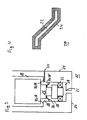
- FIG. 1 shows a first embodiment of a valve according to the invention.
- the illustrated valve 10 comprises a valve housing 14 with a valve seat 12, wherein in the interior of the valve housing 14 is a valve body 16 which is movable relative to the valve housing 14.
- the upper part of the movable valve body is formed as an electromagnetic actuator 36.
- the electromagnetic actuator 36 may be formed as a simple permanent magnet and apply a force for moving the valve body 16 by energizing a coil winding, not shown, which is arranged on the valve housing 14.
- a space 18 is formed, which is divided by a seal 20 at a sealing point 28 and an O-ring 30 in several areas.
- the O-ring 30 can usually be made of an elastomer material.
- the seal 20 arranged at the sealing point 28 comprises at least one carrier element made of metal, which may be produced, for example, from a spring steel.
- the equipped with a support member 22 made of metal Seal 20 is clamped between the valve housing 14 and the valve body 16, so that a contact pressure between the two parts holds the seal at the intended position and establishes the tight connection between the seal 20 and the valve housing 14 or the valve body 16.
- the seal 20 may be embodied, for example, as a metal bead seal, that is to say as an elastomer-coated carrier sheet.
- the seal has a defined, elastic sealing geometry, whereby it receives a long-lasting sealing effect, which can be further improved by the use of spring steel.
- the sealing effect can be achieved, for example, by a bead, that is to say a groove-shaped depression or elevation, in the seal 20, in particular in the carrier sheet.
- the bead acts as a resilient element of the seal 20 and compensates for unevenness of the movable valve body 16 and the valve housing 14.
- the subdivision of the space 18 into a plurality of mutually sealed areas creates a plurality of separate working chambers or functional spaces, which can each provide active surfaces for the pneumatic actuation of the valve 10, wherein the pneumatic control lines and connections are not shown for simplicity.
- the different working chambers or functional spaces can also release different compressed air connections assigned to the individual positions in different positions of the valve body 16.
- the simplicity Half necessary for this connection cables are also not shown.
- the seal 20 the space 18 is limited in total, that is, for a seal of the space 18 to the outside and ensures, for example, between two separate housing parts of the valve housing 14 is arranged.
- the valve body 16 is constructed of a plurality of independently movable components, for example, a plurality of magnets that are not in direct contact with each other. The enclosed between the valve housing 14 and the valve body 16 space 18 can not be simply coherent in this case, and are divided by the seal 20 several times at different locations in non-contiguous areas of the room 18 further.
- FIG. 2 shows a second embodiment of a valve according to the invention. Unlike the in FIG. 1 illustrated embodiment of the valve 10 is in the in FIG. 2 illustrated embodiment of the FIG. 1 known O-ring 30 has been replaced by a seal 20 at a sealing point 28 ', which also comprises a support made of metal.
- a seal 20 at a sealing point 28 ', which also comprises a support made of metal.
- Embodiment therefore only includes seals 20 having a support of metal.
- FIG. 3 shows a third embodiment of a valve according to the invention.
- the seal 20 at the sealing point 28 'with two perpendicular to the sealing direction superimposed sealing layers 26 executed. This can be used, for example, to improve the sealing effect of the seal 20.
- a molded seal 32 is arranged made of an elastomer material. Via a connection 34 for control air, a part of the space 18 which lies between the sealing point 28 and the sealing point 28 ', be vented. In this way, a force can be exerted on the valve body 16 via control surfaces in order to move it within the valve housing 14.
- the use or the provision of other actuators for example, from the Figures 1 and 2 known electromagnetic actuator or a return spring, is conceivable.
- FIG. 4 shows a cross section through a seal.
- the illustrated seal 20 comprises a carrier element 22 made of metal and a coating 24 which at least partially envelops the carrier element 22.
- the support member 22 may for example be made of a spring steel, so that due to the shape and the arrangement of the seal the sealing point a sealing effect is achieved.
- the support member 22 is a prerequisite for a permanent elasticity of the seal 20. In this case, a simple bead not shown in this figure in the support member 22 form an essential basis for the permanently elastic sealing effect.
- the carrier element 22 does not age or prematurely when the seal is constantly under pressure or is exposed to high operating temperatures or large temperature changes.
- the coating 24 may for example consist of a thin elastomer layer to the sealing effect of the seal 20 to the from FIGS. 1 to 3 known sealing points 28, 28 'to improve.
- the valve according to the invention is particularly stable and robust, so that its use is particularly suitable in vehicle technology, where particular emphasis is placed on a high average operating time. Particularly preferred is the use of the valve at locations in the vehicle, which reach high temperatures during operation. In particular, a pneumatic transmission control of the vehicle is to be mentioned in this context.
Landscapes
- Engineering & Computer Science (AREA)
- General Engineering & Computer Science (AREA)
- Mechanical Engineering (AREA)
- Sealing With Elastic Sealing Lips (AREA)
- Lift Valve (AREA)
- Valve Housings (AREA)
- Sealing Devices (AREA)
Description
- Die Erfindung betrifft ein Ventil mit einem gegenüber einem Ventilsitz in einem Ventilgehäuse beweglichen Ventilkörper, wobei zwischen dem Ventilkörper und dem Ventilgehäuse ein Raum gebildet wird, der durch zumindest eine Dichtung unterteilt oder begrenzt ist, wobei die zumindest eine Dichtung ein Trägerelement aus Metall umfasst, und wie es beispielsweise aus Dokument
EP-A-877 184 - Ventile, insbesondere Pneumatikventile, besitzen meist mehrere Dichtungen zur Trennung einzelner Arbeitskammern beziehungsweise einzelner Funktionsräume zwischen einem beweglichen Ventilkörper und einem Ventilgehäuse beziehungsweise zur Abdichtung des Ventilgehäuses. Die Dichtungen sind in der Regel als O-Ringe oder als aufgebrachte Formdichtungen jeweils aus Elastomerwerkstoffen realisiert. Elastomerwerkstoffe unterliegen jedoch einem Alterungsprozess, wodurch unter anderem eine nachlassende Rückstellfähigkeit mit einer daraus resultierenden Undichtigkeit der Dichtung unter Belastung resultiert.
- Insbesondere im Nutzfahrzeugbereich sind Robustheit und lange Lebensdauer, das heißt eine große mittlere Betriebsdauer, eine wichtige Vorraussetzung für den Betrieb. Unter der mittleren Betriebsdauer wird hier allgemein die Betriebsdauer bei erstmaliger Inbetriebnahme des Ventils bis zum ersten Defekt mit Ausfallwirkung verstanden, wobei eine Fehlschaltung aufgrund nachlassender Dichtungswirkung ebenfalls als Ausfall gewertet wird. Insbesondere ständig unter Druck beziehungsweise ständig hohen Temperaturen oder Temperaturwechseln ausgesetzte Ventildichtungen können die gestellten Anforderungen bezüglich der Robustheit beziehungsweise der Lebensdauer nur schwer erfüllen, wodurch verkürzte Wartungsintervalle, oder im Defektfall Fehlschaltungen, die Folge sein können.
- Der vorliegenden Erfindung liegt daher die Aufgabe zugrunde, ein Ventil bereitzustellen, das bei verringertem Montageaufwand hohen Anforderungen hinsichtlich der Lebensdauer genügt beziehungsweise beim Betrieb unter erhöhten Temperaturen oder ständigen Temperaturwechseln eine höhere mittlere Betriebsdauer aufweist.
- Diese Aufgabe wird durch die Merkmale des unabhängigen Anspruchs gelöst.
- Vorteilhafte Ausgestaltungen und Weiterbildungen der Erfindung ergeben sich aus den abhängigen Ansprüchen.
- Die Erfindung baut auf dem gattungsgemäßen Ventil dadurch auf, dass die zumindest eine Dichtung den Raum mehrfach an verschiedenen Dichtstellen unterteilt, dass der Ventilkörper aus mehreren unabhängig voneinander beweglichen Teilen aufgebaut ist und das die Dichtstellen an verschiedenen voneinander unabhängig beweglichen Teilen des Ventilkörpers angeordnet sind.
- Die Verwendung einer Dichtung mit einem Trägerelement aus Metall erlaubt eine dauerelastische Abdichtung, wobei die Elastizität durch Verwendung eines Federstahls als Trägerelement weiter erhöht werden kann. Eine derartige Dichtung weist ein geringeres Setzverhalten und eine lange Lebensdauer auf und ist dauerhaft für höhere Temperaturen geeignet. Gemäß der vorliegenden Erfindung sollen also bislang aus einem Elastomerwerkstoff hergestellte Dichtungen in dem Ventil zumindest teilweise durch metallische Dichtungen, das heißt Dichtungen, die zumindest teilweise aus einem Metall hergestellt sind, ersetzt werden.
- Insbesondere kann vorgesehen sein, dass die zumindest eine Dichtung vollständig aus Metall gefertigt ist. Ist die zumindest eine Dichtung vollständig aus Metall gefertigt, so ist die Dichtung im Vergleich zu einer aus einem Elastomer gefertigten Dichtung besonders temperaturbeständig, wodurch die mittlere Betriebsdauer bei einem Betrieb unter hohen Umgebungstemperaturen erhöht wird.
- Alternativ kann vorgesehen sein, dass die zumindest eine Dichtung eine Beschichtung aus einem Elastomer umfasst. Weist die Dichtung eine das Trägerelement umgebende Beschichtung aus einem Elastomer auf, so ist die Dichtwirkung mit einer vollständig aus einem Elastomer hergestellten Dichtung vergleichbar, weist jedoch gegenüber dieser eine höhere Temperaturbeständigkeit und eine längere Lebensdauer auf. Dies lässt sich insbesondere durch das nicht alternde Trägerelement aus Metall begründen.
- Besonders bevorzugt ist, dass das Trägerelement aus Metall zumindest eine Sicke als federndes Element umfasst. Eine Sicke, das heißt eine rinnenförmige Vertiefung beziehungsweise Erhöhung, kann zum Ausgleich von Unebenheiten an dem beweglichen Ventilkörper, zum Beispiel einem beweglichen Magneten, und dem Ventilgehäuse verwendet werden. Auf diese Weise kann eine dauerhafte ausreichende Dichtwirkung erzeugt werden.
- Weiterhin kann vorgesehen sein, dass die zumindest eine Dichtung mehrere nicht parallel zur Dichtrichtung angeordnete Dichtungslagen umfasst. Durch die Verwendung mehrerer nicht parallel zur Dichtrichtung übereinander angeordneter Dichtungslagen ist die Dichtwirkung der einzelnen Dichtungen verbesserbar. Die Anordnung der Dichtungslagen kann dabei vorzugsweise senkrecht zur Dichtrichtung erfolgen.
- Erfindungsgemäss ist vorgesehen, dass die zumindest eine Dichtung den Raum mehrfach an verschiedenen Dichtstellen unterteilt. Durch die Verwendung eines einzelnen Bauteils, welches an mehreren unterschiedlichen Dichtstellen eine Abdichtung ermöglicht, ist eine vereinfachte Montage des Ventils realisierbar.
- Erfindungsgemäss ist in diesem Zusammenhang desweiteren vorgesehen, dass der Ventilkörper aus mehreren unabhängig voneinander beweglichen Teilen aufgebaut ist und dass die Dichtstellen an verschiedenen voneinander unabhängig beweglichen Teilen des Ventilkörpers angeordnet sind. Das verwendete Bauteil kann gleichzeitig an mehreren separat beweglichen Bauteilen des Ventilkörpers eine Dichtwirkung bereitstellen.
- Es kann auch vorgesehen sein, dass der zwischen Ventilgehäuse und Ventilkörper gebildete Raum durch einen O-Ring und/oder eine aufgebrachte Formdichtung weiter unterteilt ist, wobei der O-Ring und/oder die Formdichtung aus einem Elastomer bestehen. Je nach Verwendungszweck des Ventils kann es sinnvoll sein, nur einen Teil der in dem Ventil vorhandenen Dichtungen durch eine Dichtung mit einem Trägerelement aus Metall zu ersetzen und die übrigen Dichtungen weiterhin in herkömmlicher Weise aus einem Elastomerwerkstoff zu fertigen. Dies erlaubt den Rückgriff auf bekannte Fertigungsverfahren und ist, insbesondere falls nicht alle Dichtungen des Ventils erhöhten Belastungen ausgesetzt sind, hinsichtlich der mittleren Betriebsdauer nicht von Nachteil.
- Es kann vorgesehen sein, dass das Ventil ein 2/2-Wegeventil ist. Ein 2/2-Wegeventil ist ein häufig verwendetes Ventil, das auch in für die Lebensdauer des Ventils ungünstigen Umgebungen eingesetzt wird.
- Alternativ kann auch vorgesehen sein, dass das Ventil ein 3/2-Wegeventil ist. Auch 3/2-Wegeventile werden häufig in für die Lebensdauer ungünstigen Umgebungen eingesetzt.
- Im Zusammenhang mit der vorliegenden Erfindung ist es von besonderem Vorteil, wenn eine pneumatische Getriebesteuerung mit zumindest einem erfindungsgemäßen Ventil ausgestattet ist. Gerade eine pneumatische Getriebesteuerung ist aufgrund häufiger Schaltvorgänge, hohen Betriebstemperaturen beziehungsweise ständigen Temperaturschwankungen und dauerhaft an den Ventilen der pneumatischen Getriebesteuerung anliegenden hohen Schaltdrücken auf Ventile mit einer hohen mittleren Betriebsdauer angewiesen. Eine pneumatische Getriebesteuerung stellt also hohe Anforderungen an die verwendeten Ventile.
- Die Erfindung wird nun mit Bezug auf die begleitenden Zeichnungen anhand besonders bevorzugter Ausführungsformen beispielhaft erläutert.
- Es zeigen:
- Figur 1
- eine erste Ausführungsform eines erfindungsgemäßen Ventils;
- Figur 2
- eine zweite Ausführungsform eines erfindungsgemäßen Ventils;
- Figur 3
- eine dritte Ausführungsform eines erfindungsgemäßen Ventils und
- Figur 4
- einen Querschnitt durch eine Dichtung.
- In den folgenden Zeichnungen bezeichnen gleiche Bezugszeichen gleiche oder gleichartige Teile.
-
Figur 1 zeigt eine erste Ausführungsform eines erfindungsgemäßen Ventils. Das dargestellte Ventil 10 umfasst ein Ventilgehäuse 14 mit einem Ventilsitz 12, wobei sich im Inneren des Ventilgehäuses 14 ein Ventilkörper 16 befindet, der gegenüber dem Ventilgehäuse 14 beweglich ist. Der obere Teil des beweglichen Ventilkörpers ist als eine elektromagnetische Betätigungseinrichtung 36 ausgebildet. Beispielsweise kann die elektromagnetische Betätigungseinrichtung 36 als ein einfacher Permanentmagnet ausgebildet sein und durch das Bestromen einer nicht dargestellten Spulenwicklung, die an dem Ventilgehäuse 14 angeordnet ist, eine Kraft zum Bewegen des Ventilkörpers 16 aufbringen. Zwischen dem Ventilkörper 16 und dem Ventilgehäuse 14 wird ein Raum 18 gebildet, der durch eine Dichtung 20 an einer Dichtstelle 28 und einen O-Ring 30 in mehrere Bereiche unterteilt wird. Der O-Ring 30 kann dabei üblicherweise aus einem Elastomerwerkstoff hergestellt sein. Die an der Dichtstelle 28 angeordnete Dichtung 20 umfasst zumindest ein Trägerelement aus Metall, das beispielsweise aus einem Federstahl hergestellt sein kann. Die mit einem Trägerelement 22 aus Metall ausgestattete Dichtung 20 ist zwischen dem Ventilgehäuse 14 und dem Ventilkörper 16 verspannt, so dass ein Anpressdruck zwischen den beiden Teilen die Dichtung an der vorgesehenen Position hält und die dichte Verbindung zwischen der Dichtung 20 und dem Ventilgehäuse 14 beziehungsweise dem Ventilkörper 16 herstellt. Die Dichtung 20 kann beispielsweise als eine Metallsickendichtung, das heißt als ein elastomerbeschichtetes Trägerblech, ausgeführt sein. Bei einer derartigen Ausführungsform besitzt die Dichtung eine definierte, elastische Dichtgeometrie, wodurch sie eine lang anhaltende Dichtwirkung erhält, die durch die Verwendung von Federstahl nochmals verbessert werden kann. Die Dichtwirkung kann beispielsweise durch eine Sicke, das heißt eine rinnenförmige Vertiefung beziehungsweise Erhöhung, in der Dichtung 20, insbesondere in dem Trägerblech, erzielt werden. Die Sicke wirkt als federndes Element der Dichtung 20 und gleicht Unebenheiten des beweglichen Ventilkörpers 16 und des Ventilgehäuses 14 aus. Die Unterteilung des Raums 18 in mehrere gegeneinander abgedichtete Bereiche erzeugt mehrere voneinander getrennte Arbeitskammern beziehungsweise Funktionsräume, die jeweils Wirkflächen zum pneumatischen Ansteuern des Ventils 10 bereitstellen können, wobei die pneumatischen Steuerleitungen und Anschlüsse der Einfachheit halber nicht dargestellt sind. Die verschiedenen Arbeitskammern beziehungsweise Funktionsräume können jedoch auch in unterschiedlichen Positionen des Ventilkörpers 16 den einzelnen Positionen zugeordnete unterschiedliche Druckluftverbindungen freigeben. Der Einfachheit halber sind hierfür notwendige Anschlussleitungen ebenfalls nicht dargestellt. Durch die Verwendung eines Trägerelements aus Metall kann bei geeigneter Formgebung die notwendige Bauhöhe im Bereich der Dichtstelle 28 gegenüber einer herkömmlichen Elastomerdichtung verringert werden, wodurch die Baulänge des Ventils 10 verringert werden kann. Denkbar ist auch, dass die Dichtung 20 den Raum 18 insgesamt begrenzt, dass heißt für eine Abdichtung des Raumes 18 nach außen hin sorgt und dabei beispielsweise zwischen zwei separaten Gehäuseteilen des Ventilgehäuses 14 angeordnet ist. Weiterhin ist es möglich, dass der Ventilkörper 16 aus mehreren voneinander unabhängig beweglichen Bauteilen aufgebaut ist, zum Beispiel mehreren Magneten, die nicht in direktem Kontakt zueinander stehen. Der zwischen Ventilgehäuse 14 und Ventilkörper 16 eingeschlossene Raum 18 kann in diesem Fall auch nicht einfach zusammenhängend sein und von der Dichtung 20 mehrfach an verschiedenen Stellen in nicht zusammenhängenden Bereichen des Raumes 18 weiter unterteilt werden. -
Figur 2 zeigt eine zweite Ausführungsform eines erfindungsgemäßen Ventils. Im Gegensatz zu der inFigur 1 dargestellten Ausführungsform des Ventils 10 ist bei der inFigur 2 dargestellten Ausführungsform der aus derFigur 1 bekannte O-Ring 30 durch eine Dichtung 20 an einer Dichtstelle 28' ersetzt worden, die ebenfalls einen Träger aus Metall umfasst. Die inFigur 2 dargestellte - Ausführungsform umfasst daher nur noch Dichtungen 20, die einen Träger aus Metall aufweisen.
-
Figur 3 zeigt eine dritte Ausführungsform eines erfindungsgemäßen Ventils. Bei der inFigur 3 dargestellten Ausführungsform des Ventils 10 ist die Dichtung 20 an der Dichtstelle 28' mit zwei senkrecht zur Dichtungsrichtung übereinander liegenden Dichtungslagen 26 ausgeführt. Dies kann beispielsweise zum Verbessern der Dichtwirkung der Dichtung 20 verwendet werden. Weiterhin ist an dem dem Ventilsitz des Ventils 10 zugewandten Ende des Ventilkörpers 16 eine Formdichtung 32 aus einem Elastomerwerkstoff angeordnet. Über einen Anschluss 34 für Steuerluft kann ein Teil des Raumes 18, der zwischen der Dichtstelle 28 und der Dichtstelle 28' liegt, belüftet werden. Auf diese Weise kann über Steuerflächen eine Kraft auf den Ventilkörper 16 ausgeübt werden, um diesen innerhalb des Ventilgehäuses 14 zu bewegen. Die Verwendung beziehungsweise das Vorsehen weiterer Betätigungseinrichtungen, zum Beispiel der aus denFiguren 1 und 2 bekannten elektromagnetischen Betätigungseinrichtung oder einer Rückstellfeder, ist denkbar. -
Figur 4 zeigt einen Querschnitt durch eine Dichtung. Die dargestellte Dichtung 20 umfasst ein Trägerelement 22 aus Metall und eine Beschichtung 24, die das Trägerelement 22 zumindest teilweise einhüllt. Das Trägerelement 22 kann beispielsweise aus einem Federstahl gefertigt sein, so dass aufgrund der Form und der Anordnung der Dichtung an der Dichtstelle eine Dichtwirkung erzielbar ist. Das Trägerelement 22 ist Vorraussetzung für eine Dauerelastizität der Dichtung 20. Dabei kann eine einfache in dieser Figur nicht dargestellte Sicke in dem Trägerelement 22 eine wesentliche Grundlage für die dauerelastische Dichtwirkung bilden. Insbesondere altert das Trägerelement 22 nicht beziehungsweise nicht vorzeitig, wenn die Dichtung dauernd unter Druck steht beziehungsweise hohen Betriebstemperaturen oder großen Temperaturwechseln ausgesetzt wird. Die Beschichtung 24 kann beispielsweise aus einer dünnen Elastomerschicht bestehen, um die Dichtwirkung der Dichtung 20 an den aus denFiguren 1 bis 3 bekannten Dichtstellen 28, 28' zu verbessern. - Das erfindungsgemäße Ventil ist besonders standfest und robust, so dass sich sein Einsatz insbesondere in der Fahrzeugtechnik anbietet, wo besonderer Wert auf eine hohe mittlere Betriebsdauer gelegt wird. Besonders bevorzugt ist dabei die Verwendung des Ventils an Stellen im Fahrzeug, die während des Betriebs hohe Temperaturen erreichen. Insbesondere ist in diesem Zusammenhang eine pneumatische Getriebesteuerung des Fahrzeugs zu nennen.
-
- 10
- Ventil
- 12
- Ventilsitz
- 14
- Ventilgehäuse
- 16
- Ventilkörper
- 18
- Raum
- 20
- Dichtung
- 22
- Trägerelement
- 24
- Beschichtung
- 26
- Dichtungslage
- 28
- Dichtstelle
- 28'
- Dichtstelle
- 30
- O-Ring
- 32
- Formdichtung
- 34
- Anschluss Steuerluft
- 36
- elektromagnetische Betätigungseinrichtung
Claims (9)
- Ventil (10) mit einem gegenüber einem Ventilsitz (12) in einem Ventilgehäuse (14) beweglichen Ventilkörper (16), wobei zwischen dem Ventilkörper (16) und dem Ventilgehäuse (14) ein Raum (18) gebildet wird, der durch zumindest eine Dichtung (20) unterteilt oder begrenzt ist, wobei die zumindest eine Dichtung (20) ein Träger-element (22) aus Metall umfasst, dadurch gekennzeichnet,- dass die zumindest eine Dichtung (20) den Raum (18) mehrfach an verschiedenen Dichtstellen (28, 28') unterteilt,- dass der Ventilkörper (16) aus mehreren unabhängig voneinander beweglichen Teilen aufgebaut ist und- dass die Dichtstellen (28, 28') an verschiedenen voneinander unabhängig beweglichen Teilen des Ventilkörpers (16) angeordnet sind.
- Ventil (10) gemäß Anspruch 1, dadurch gekennzeichnet, dass die zumindest eine Dichtung (20) vollständig aus Metall gefertigt ist.
- Ventil (10) gemäß Anspruch 1, dadurch gekennzeichnet, dass die zumindest eine Dichtung (20) eine Beschichtung (24) aus einem Elastomer umfasst.
- Ventil (10) gemäß einem der vorhergehenden Ansprüche, dadurch gekennzeichnet, dass das Trägerelement (22) aus Metall zumindest eine Sicke als federndes Element umfasst.
- Ventil (10) gemäß einem der vorhergehenden Ansprüche, dadurch gekennzeichnet, dass die zumindest eine Dichtung (20) mehrere nicht parallel zur Dichtrichtung angeordnete Dichtungslagen (26) umfasst.
- Ventil (10) gemäß einem der vorhergehenden Ansprüche, dadurch gekennzeichnet, dass der zwischen Ventilgehäuse (14) und Ventilkörper (16) gebildete Raum (18) durch einen O-Ring (30) und/oder eine aufgebrachte Formdichtung (32) weiter unterteilt ist, wobei der O-Ring (30) und/oder die Formdichtung (32) aus einem Elastomer bestehen.
- Ventil (10) gemäß einem der vorhergehenden Ansprüche, dadurch gekennzeichnet, dass das Ventil (10) ein 2/2-Wegeventil ist.
- Ventil (10) gemäß einem der Ansprüche 1 bis 6, dadurch gekennzeichnet, dass das Ventil (10) ein 3/2-Wegeventil ist.
- Pneumatische Getriebesteuerung mit einem Ventil (10) gemäß einem der vorhergehenden Ansprüche.
Applications Claiming Priority (2)
| Application Number | Priority Date | Filing Date | Title |
|---|---|---|---|
| DE102008032716A DE102008032716B4 (de) | 2008-07-11 | 2008-07-11 | Ventil mit hoher mittlerer Betriebsdauer |
| PCT/EP2009/004861 WO2010003608A1 (de) | 2008-07-11 | 2009-07-06 | Ventil mit hoher mittlerer betriebsdauer |
Publications (2)
| Publication Number | Publication Date |
|---|---|
| EP2297498A1 EP2297498A1 (de) | 2011-03-23 |
| EP2297498B1 true EP2297498B1 (de) | 2014-09-10 |
Family
ID=41010251
Family Applications (1)
| Application Number | Title | Priority Date | Filing Date |
|---|---|---|---|
| EP09776972.3A Not-in-force EP2297498B1 (de) | 2008-07-11 | 2009-07-06 | Ventil mit hoher mittlerer betriebsdauer |
Country Status (5)
| Country | Link |
|---|---|
| US (1) | US20110180742A1 (de) |
| EP (1) | EP2297498B1 (de) |
| CN (1) | CN102089560B (de) |
| DE (1) | DE102008032716B4 (de) |
| WO (1) | WO2010003608A1 (de) |
Family Cites Families (23)
| Publication number | Priority date | Publication date | Assignee | Title |
|---|---|---|---|---|
| US2808484A (en) * | 1952-05-21 | 1957-10-01 | Manning Maxwell & Moore Inc | Pressure operated switch |
| US3550847A (en) * | 1969-05-05 | 1970-12-29 | Robertshaw Controls Co | Pneumatically operated logic system or the like |
| US3888143A (en) * | 1972-04-04 | 1975-06-10 | Ford Motor Co | Dual diaphragm actuator for a transmission throttle valve assembly |
| US3968971A (en) * | 1973-05-22 | 1976-07-13 | Automatisation - Sogemo | Fluid-tight packing |
| US3874636A (en) * | 1973-11-19 | 1975-04-01 | Rockwell International Corp | Sealed valve and related structure |
| US4462568A (en) * | 1982-03-15 | 1984-07-31 | Xomox Corporation | Valve construction and method of making the same |
| DE3220481C1 (de) * | 1982-05-29 | 1983-12-22 | Klinger AG, 6301 Zug | Dichtungsanordnung |
| US4486002A (en) * | 1982-09-24 | 1984-12-04 | Fmc Corporation | Combined metallic and flexible non-metallic pressure seal |
| US4917357A (en) * | 1988-09-26 | 1990-04-17 | Nupro Company | Diaphragm valve |
| US5009778A (en) * | 1989-02-27 | 1991-04-23 | Hewlett-Packard Company | Axially-driven valve controlled fluid trapping assembly |
| US5217043A (en) * | 1990-04-19 | 1993-06-08 | Milic Novakovic | Control valve |
| DE4028234C2 (de) * | 1990-09-06 | 1996-08-14 | Festo Kg | Pneumatisches Ventil |
| DE4224180A1 (de) * | 1992-07-22 | 1994-01-27 | Freudenberg Carl Fa | Schieberventildichtung |
| US5725007A (en) * | 1995-07-07 | 1998-03-10 | Stubbs; William L. | Valve mechanism and method for making same |
| DE19719767A1 (de) * | 1997-05-10 | 1998-11-19 | Herion Werke Gmbh & Co Kg | Mehrwegeventil |
| CN2382902Y (zh) * | 1998-08-13 | 2000-06-14 | 中国核工业总公司苏州阀门厂 | 蝶阀用全金属弹性密封环 |
| JP2000352468A (ja) * | 1999-06-14 | 2000-12-19 | Asahi Organic Chem Ind Co Ltd | 自動弁 |
| JP4928681B2 (ja) * | 2001-06-07 | 2012-05-09 | 三菱重工業株式会社 | メタルパッキン |
| WO2005024281A1 (ja) * | 2003-08-27 | 2005-03-17 | Koganei Corporation | 方向制御弁 |
| JP4307213B2 (ja) * | 2003-10-17 | 2009-08-05 | 三菱電機株式会社 | バルブ及び排気ガス再循環制御用バルブ又はバルブの組立て方法 |
| DE102004007091B3 (de) * | 2004-02-13 | 2005-07-28 | Festo Ag & Co. | Ventil |
| DE102004035285A1 (de) * | 2004-07-21 | 2006-02-16 | Federal-Mogul Sealing Systems Bretten Gmbh | Verfahren zur Herstellung von Trägerelementen für Elastomerdichtungen |
| US7735803B2 (en) * | 2004-08-12 | 2010-06-15 | Borgwarner, Inc. | Low friction sliding valve seal |
-
2008
- 2008-07-11 DE DE102008032716A patent/DE102008032716B4/de not_active Expired - Fee Related
-
2009
- 2009-07-06 WO PCT/EP2009/004861 patent/WO2010003608A1/de not_active Ceased
- 2009-07-06 CN CN200980127047.1A patent/CN102089560B/zh not_active Expired - Fee Related
- 2009-07-06 EP EP09776972.3A patent/EP2297498B1/de not_active Not-in-force
-
2011
- 2011-01-10 US US12/987,563 patent/US20110180742A1/en not_active Abandoned
Also Published As
| Publication number | Publication date |
|---|---|
| WO2010003608A1 (de) | 2010-01-14 |
| CN102089560A (zh) | 2011-06-08 |
| DE102008032716B4 (de) | 2011-03-31 |
| DE102008032716A1 (de) | 2010-01-21 |
| WO2010003608A8 (de) | 2010-03-04 |
| EP2297498A1 (de) | 2011-03-23 |
| US20110180742A1 (en) | 2011-07-28 |
| CN102089560B (zh) | 2015-08-05 |
Similar Documents
| Publication | Publication Date | Title |
|---|---|---|
| DE102013103606B4 (de) | Fluidisches Steuerelement | |
| EP2467629A1 (de) | Federelastische axiale dichtung | |
| WO2019034401A1 (de) | Dichtungsanordnung | |
| EP3762637B1 (de) | Dichtungsanordnung und fluidregelventil | |
| WO2019197321A1 (de) | Dichtung und fluidventil | |
| EP2239173B1 (de) | Pneumatisch gesteuertes 3/2-Wegeventil zur Steuerung einer pneumatischen Feststellbremse und Verfahren zum Betreiben eines derartigen Ventils | |
| EP1717501A1 (de) | Ventil | |
| WO2015022144A1 (de) | Dichtring | |
| WO2010118834A1 (de) | Ventilschaftdichtung | |
| DE102014219460A1 (de) | Vorrichtung zur Dichtung eines Ventils | |
| EP1340010B2 (de) | Flachdichtung für eine kolbenkraft- oder arbeitsmaschine | |
| DE102016109129A1 (de) | Membranventil | |
| DE102008032716B4 (de) | Ventil mit hoher mittlerer Betriebsdauer | |
| EP2213911B1 (de) | Dichtung, Dichtungsanordnung damit und deren Verwendung | |
| EP2738432B1 (de) | Ventilmodul mit elektropneumatischen Ventilen | |
| DE102008029642A1 (de) | Tellerfederanordnung | |
| WO2019170735A1 (de) | Dichtungsanordnung und fluidregelventil | |
| DE3719189A1 (de) | Dichtungsring | |
| EP3146245B1 (de) | Mehrwegeventil | |
| EP1847736B1 (de) | Dichtungsanordnung | |
| WO2012107354A1 (de) | Dichtungsanordnung | |
| DE102008030787A1 (de) | Zylinderkopfdichtung | |
| EP1353085B1 (de) | Dichtungsanordnung, insbesondere eines Luftfedersystems | |
| EP4379234A1 (de) | Kolben-zylinder-anordnung, vorzugsweise für ein fahrzeug | |
| DE102014210431A1 (de) | Sicherheitsventil |
Legal Events
| Date | Code | Title | Description |
|---|---|---|---|
| PUAI | Public reference made under article 153(3) epc to a published international application that has entered the european phase |
Free format text: ORIGINAL CODE: 0009012 |
|
| 17P | Request for examination filed |
Effective date: 20110211 |
|
| AK | Designated contracting states |
Kind code of ref document: A1 Designated state(s): AT BE BG CH CY CZ DE DK EE ES FI FR GB GR HR HU IE IS IT LI LT LU LV MC MK MT NL NO PL PT RO SE SI SK SM TR |
|
| AX | Request for extension of the european patent |
Extension state: AL BA RS |
|
| DAX | Request for extension of the european patent (deleted) | ||
| GRAP | Despatch of communication of intention to grant a patent |
Free format text: ORIGINAL CODE: EPIDOSNIGR1 |
|
| INTG | Intention to grant announced |
Effective date: 20140206 |
|
| GRAS | Grant fee paid |
Free format text: ORIGINAL CODE: EPIDOSNIGR3 |
|
| GRAA | (expected) grant |
Free format text: ORIGINAL CODE: 0009210 |
|
| AK | Designated contracting states |
Kind code of ref document: B1 Designated state(s): AT BE BG CH CY CZ DE DK EE ES FI FR GB GR HR HU IE IS IT LI LT LU LV MC MK MT NL NO PL PT RO SE SI SK SM TR |
|
| REG | Reference to a national code |
Ref country code: GB Ref legal event code: FG4D Free format text: NOT ENGLISH |
|
| REG | Reference to a national code |
Ref country code: CH Ref legal event code: EP |
|
| REG | Reference to a national code |
Ref country code: IE Ref legal event code: FG4D Free format text: LANGUAGE OF EP DOCUMENT: GERMAN |
|
| REG | Reference to a national code |
Ref country code: AT Ref legal event code: REF Ref document number: 686868 Country of ref document: AT Kind code of ref document: T Effective date: 20141015 |
|
| REG | Reference to a national code |
Ref country code: DE Ref legal event code: R096 Ref document number: 502009009949 Country of ref document: DE Effective date: 20141023 |
|
| REG | Reference to a national code |
Ref country code: SE Ref legal event code: TRGR |
|
| PG25 | Lapsed in a contracting state [announced via postgrant information from national office to epo] |
Ref country code: LT Free format text: LAPSE BECAUSE OF FAILURE TO SUBMIT A TRANSLATION OF THE DESCRIPTION OR TO PAY THE FEE WITHIN THE PRESCRIBED TIME-LIMIT Effective date: 20140910 Ref country code: ES Free format text: LAPSE BECAUSE OF FAILURE TO SUBMIT A TRANSLATION OF THE DESCRIPTION OR TO PAY THE FEE WITHIN THE PRESCRIBED TIME-LIMIT Effective date: 20140910 Ref country code: FI Free format text: LAPSE BECAUSE OF FAILURE TO SUBMIT A TRANSLATION OF THE DESCRIPTION OR TO PAY THE FEE WITHIN THE PRESCRIBED TIME-LIMIT Effective date: 20140910 Ref country code: NO Free format text: LAPSE BECAUSE OF FAILURE TO SUBMIT A TRANSLATION OF THE DESCRIPTION OR TO PAY THE FEE WITHIN THE PRESCRIBED TIME-LIMIT Effective date: 20141210 Ref country code: GR Free format text: LAPSE BECAUSE OF FAILURE TO SUBMIT A TRANSLATION OF THE DESCRIPTION OR TO PAY THE FEE WITHIN THE PRESCRIBED TIME-LIMIT Effective date: 20141211 |
|
| REG | Reference to a national code |
Ref country code: NL Ref legal event code: VDEP Effective date: 20140910 |
|
| REG | Reference to a national code |
Ref country code: LT Ref legal event code: MG4D |
|
| PG25 | Lapsed in a contracting state [announced via postgrant information from national office to epo] |
Ref country code: HR Free format text: LAPSE BECAUSE OF FAILURE TO SUBMIT A TRANSLATION OF THE DESCRIPTION OR TO PAY THE FEE WITHIN THE PRESCRIBED TIME-LIMIT Effective date: 20140910 Ref country code: CY Free format text: LAPSE BECAUSE OF FAILURE TO SUBMIT A TRANSLATION OF THE DESCRIPTION OR TO PAY THE FEE WITHIN THE PRESCRIBED TIME-LIMIT Effective date: 20140910 Ref country code: LV Free format text: LAPSE BECAUSE OF FAILURE TO SUBMIT A TRANSLATION OF THE DESCRIPTION OR TO PAY THE FEE WITHIN THE PRESCRIBED TIME-LIMIT Effective date: 20140910 |
|
| PG25 | Lapsed in a contracting state [announced via postgrant information from national office to epo] |
Ref country code: NL Free format text: LAPSE BECAUSE OF FAILURE TO SUBMIT A TRANSLATION OF THE DESCRIPTION OR TO PAY THE FEE WITHIN THE PRESCRIBED TIME-LIMIT Effective date: 20140910 |
|
| PG25 | Lapsed in a contracting state [announced via postgrant information from national office to epo] |
Ref country code: EE Free format text: LAPSE BECAUSE OF FAILURE TO SUBMIT A TRANSLATION OF THE DESCRIPTION OR TO PAY THE FEE WITHIN THE PRESCRIBED TIME-LIMIT Effective date: 20140910 Ref country code: CZ Free format text: LAPSE BECAUSE OF FAILURE TO SUBMIT A TRANSLATION OF THE DESCRIPTION OR TO PAY THE FEE WITHIN THE PRESCRIBED TIME-LIMIT Effective date: 20140910 Ref country code: SK Free format text: LAPSE BECAUSE OF FAILURE TO SUBMIT A TRANSLATION OF THE DESCRIPTION OR TO PAY THE FEE WITHIN THE PRESCRIBED TIME-LIMIT Effective date: 20140910 Ref country code: RO Free format text: LAPSE BECAUSE OF FAILURE TO SUBMIT A TRANSLATION OF THE DESCRIPTION OR TO PAY THE FEE WITHIN THE PRESCRIBED TIME-LIMIT Effective date: 20140910 Ref country code: PT Free format text: LAPSE BECAUSE OF FAILURE TO SUBMIT A TRANSLATION OF THE DESCRIPTION OR TO PAY THE FEE WITHIN THE PRESCRIBED TIME-LIMIT Effective date: 20150112 Ref country code: IS Free format text: LAPSE BECAUSE OF FAILURE TO SUBMIT A TRANSLATION OF THE DESCRIPTION OR TO PAY THE FEE WITHIN THE PRESCRIBED TIME-LIMIT Effective date: 20150110 |
|
| PG25 | Lapsed in a contracting state [announced via postgrant information from national office to epo] |
Ref country code: PL Free format text: LAPSE BECAUSE OF FAILURE TO SUBMIT A TRANSLATION OF THE DESCRIPTION OR TO PAY THE FEE WITHIN THE PRESCRIBED TIME-LIMIT Effective date: 20140910 |
|
| REG | Reference to a national code |
Ref country code: DE Ref legal event code: R097 Ref document number: 502009009949 Country of ref document: DE |
|
| PLBE | No opposition filed within time limit |
Free format text: ORIGINAL CODE: 0009261 |
|
| STAA | Information on the status of an ep patent application or granted ep patent |
Free format text: STATUS: NO OPPOSITION FILED WITHIN TIME LIMIT |
|
| PG25 | Lapsed in a contracting state [announced via postgrant information from national office to epo] |
Ref country code: DK Free format text: LAPSE BECAUSE OF FAILURE TO SUBMIT A TRANSLATION OF THE DESCRIPTION OR TO PAY THE FEE WITHIN THE PRESCRIBED TIME-LIMIT Effective date: 20140910 |
|
| 26N | No opposition filed |
Effective date: 20150611 |
|
| PG25 | Lapsed in a contracting state [announced via postgrant information from national office to epo] |
Ref country code: IT Free format text: LAPSE BECAUSE OF FAILURE TO SUBMIT A TRANSLATION OF THE DESCRIPTION OR TO PAY THE FEE WITHIN THE PRESCRIBED TIME-LIMIT Effective date: 20140910 |
|
| PG25 | Lapsed in a contracting state [announced via postgrant information from national office to epo] |
Ref country code: SI Free format text: LAPSE BECAUSE OF FAILURE TO SUBMIT A TRANSLATION OF THE DESCRIPTION OR TO PAY THE FEE WITHIN THE PRESCRIBED TIME-LIMIT Effective date: 20140910 |
|
| PG25 | Lapsed in a contracting state [announced via postgrant information from national office to epo] |
Ref country code: MC Free format text: LAPSE BECAUSE OF FAILURE TO SUBMIT A TRANSLATION OF THE DESCRIPTION OR TO PAY THE FEE WITHIN THE PRESCRIBED TIME-LIMIT Effective date: 20140910 |
|
| REG | Reference to a national code |
Ref country code: CH Ref legal event code: PL |
|
| GBPC | Gb: european patent ceased through non-payment of renewal fee |
Effective date: 20150706 |
|
| PG25 | Lapsed in a contracting state [announced via postgrant information from national office to epo] |
Ref country code: LU Free format text: LAPSE BECAUSE OF FAILURE TO SUBMIT A TRANSLATION OF THE DESCRIPTION OR TO PAY THE FEE WITHIN THE PRESCRIBED TIME-LIMIT Effective date: 20150706 |
|
| REG | Reference to a national code |
Ref country code: IE Ref legal event code: MM4A |
|
| PG25 | Lapsed in a contracting state [announced via postgrant information from national office to epo] |
Ref country code: LI Free format text: LAPSE BECAUSE OF NON-PAYMENT OF DUE FEES Effective date: 20150731 Ref country code: GB Free format text: LAPSE BECAUSE OF NON-PAYMENT OF DUE FEES Effective date: 20150706 Ref country code: CH Free format text: LAPSE BECAUSE OF NON-PAYMENT OF DUE FEES Effective date: 20150731 |
|
| REG | Reference to a national code |
Ref country code: FR Ref legal event code: ST Effective date: 20160331 |
|
| PG25 | Lapsed in a contracting state [announced via postgrant information from national office to epo] |
Ref country code: FR Free format text: LAPSE BECAUSE OF NON-PAYMENT OF DUE FEES Effective date: 20150731 |
|
| PG25 | Lapsed in a contracting state [announced via postgrant information from national office to epo] |
Ref country code: IE Free format text: LAPSE BECAUSE OF NON-PAYMENT OF DUE FEES Effective date: 20150706 |
|
| REG | Reference to a national code |
Ref country code: AT Ref legal event code: MM01 Ref document number: 686868 Country of ref document: AT Kind code of ref document: T Effective date: 20150706 |
|
| PG25 | Lapsed in a contracting state [announced via postgrant information from national office to epo] |
Ref country code: AT Free format text: LAPSE BECAUSE OF NON-PAYMENT OF DUE FEES Effective date: 20150706 |
|
| PG25 | Lapsed in a contracting state [announced via postgrant information from national office to epo] |
Ref country code: MT Free format text: LAPSE BECAUSE OF FAILURE TO SUBMIT A TRANSLATION OF THE DESCRIPTION OR TO PAY THE FEE WITHIN THE PRESCRIBED TIME-LIMIT Effective date: 20140910 |
|
| PG25 | Lapsed in a contracting state [announced via postgrant information from national office to epo] |
Ref country code: BG Free format text: LAPSE BECAUSE OF FAILURE TO SUBMIT A TRANSLATION OF THE DESCRIPTION OR TO PAY THE FEE WITHIN THE PRESCRIBED TIME-LIMIT Effective date: 20140910 Ref country code: SM Free format text: LAPSE BECAUSE OF FAILURE TO SUBMIT A TRANSLATION OF THE DESCRIPTION OR TO PAY THE FEE WITHIN THE PRESCRIBED TIME-LIMIT Effective date: 20140910 Ref country code: HU Free format text: LAPSE BECAUSE OF FAILURE TO SUBMIT A TRANSLATION OF THE DESCRIPTION OR TO PAY THE FEE WITHIN THE PRESCRIBED TIME-LIMIT; INVALID AB INITIO Effective date: 20090706 |
|
| PG25 | Lapsed in a contracting state [announced via postgrant information from national office to epo] |
Ref country code: BE Free format text: LAPSE BECAUSE OF NON-PAYMENT OF DUE FEES Effective date: 20150731 |
|
| PG25 | Lapsed in a contracting state [announced via postgrant information from national office to epo] |
Ref country code: TR Free format text: LAPSE BECAUSE OF FAILURE TO SUBMIT A TRANSLATION OF THE DESCRIPTION OR TO PAY THE FEE WITHIN THE PRESCRIBED TIME-LIMIT Effective date: 20140910 |
|
| PG25 | Lapsed in a contracting state [announced via postgrant information from national office to epo] |
Ref country code: MK Free format text: LAPSE BECAUSE OF FAILURE TO SUBMIT A TRANSLATION OF THE DESCRIPTION OR TO PAY THE FEE WITHIN THE PRESCRIBED TIME-LIMIT Effective date: 20140910 |
|
| PGFP | Annual fee paid to national office [announced via postgrant information from national office to epo] |
Ref country code: DE Payment date: 20190723 Year of fee payment: 11 Ref country code: SE Payment date: 20190725 Year of fee payment: 11 |
|
| REG | Reference to a national code |
Ref country code: DE Ref legal event code: R119 Ref document number: 502009009949 Country of ref document: DE |
|
| REG | Reference to a national code |
Ref country code: SE Ref legal event code: EUG |
|
| PG25 | Lapsed in a contracting state [announced via postgrant information from national office to epo] |
Ref country code: DE Free format text: LAPSE BECAUSE OF NON-PAYMENT OF DUE FEES Effective date: 20210202 Ref country code: SE Free format text: LAPSE BECAUSE OF NON-PAYMENT OF DUE FEES Effective date: 20200707 |