EP2296974B1 - Method for positioning a loaded bag in a vacuum chamber - Google Patents
Method for positioning a loaded bag in a vacuum chamber Download PDFInfo
- Publication number
- EP2296974B1 EP2296974B1 EP09755248A EP09755248A EP2296974B1 EP 2296974 B1 EP2296974 B1 EP 2296974B1 EP 09755248 A EP09755248 A EP 09755248A EP 09755248 A EP09755248 A EP 09755248A EP 2296974 B1 EP2296974 B1 EP 2296974B1
- Authority
- EP
- European Patent Office
- Prior art keywords
- bag
- loaded
- vacuum
- loaded bag
- conveyor
- Prior art date
- Legal status (The legal status is an assumption and is not a legal conclusion. Google has not performed a legal analysis and makes no representation as to the accuracy of the status listed.)
- Not-in-force
Links
Images


Classifications
-
- G—PHYSICS
- G01—MEASURING; TESTING
- G01B—MEASURING LENGTH, THICKNESS OR SIMILAR LINEAR DIMENSIONS; MEASURING ANGLES; MEASURING AREAS; MEASURING IRREGULARITIES OF SURFACES OR CONTOURS
- G01B11/00—Measuring arrangements characterised by the use of optical techniques
- G01B11/02—Measuring arrangements characterised by the use of optical techniques for measuring length, width or thickness
- G01B11/04—Measuring arrangements characterised by the use of optical techniques for measuring length, width or thickness specially adapted for measuring length or width of objects while moving
-
- B—PERFORMING OPERATIONS; TRANSPORTING
- B65—CONVEYING; PACKING; STORING; HANDLING THIN OR FILAMENTARY MATERIAL
- B65B—MACHINES, APPARATUS OR DEVICES FOR, OR METHODS OF, PACKAGING ARTICLES OR MATERIALS; UNPACKING
- B65B31/00—Packaging articles or materials under special atmospheric or gaseous conditions; Adding propellants to aerosol containers
- B65B31/02—Filling, closing, or filling and closing, containers or wrappers in chambers maintained under vacuum or superatmospheric pressure or containing a special atmosphere, e.g. of inert gas
- B65B31/024—Filling, closing, or filling and closing, containers or wrappers in chambers maintained under vacuum or superatmospheric pressure or containing a special atmosphere, e.g. of inert gas specially adapted for wrappers or bags
-
- B—PERFORMING OPERATIONS; TRANSPORTING
- B65—CONVEYING; PACKING; STORING; HANDLING THIN OR FILAMENTARY MATERIAL
- B65B—MACHINES, APPARATUS OR DEVICES FOR, OR METHODS OF, PACKAGING ARTICLES OR MATERIALS; UNPACKING
- B65B57/00—Automatic control, checking, warning, or safety devices
Definitions
- the present invention relates to a method for positioning a loaded bag in a vacuum chamber.
- Vacuum packaging in heat sealable plastic bags is a conventional way of packaging food products such as meat, and cheese.
- Vacuum packaging typically involves placing the food item in a heat sealable plastic bag having a bag mouth, and then evacuating air from the bag through the bag mouth and collapsing the bag about the contained food item. The bag is then heat sealed in its evacuated condition so the food item becomes encased in a generally air-free environment.
- the bag is a heat shrinkable bag, and after the heat sealing step, is advanced to a hot water or hot air shrink tunnel to induce shrinkage of the bag around the food item.
- Vacuum packaging machines of a known type include a vacuum chamber arranged to receive unsealed loaded bags and operable to perform a vacuum sealing operation on the loaded bags.
- the loaded bags contain products such as meat cuts, arranged in bags formed by a heat-shrinkable film.
- the vacuum sealing operation typically includes vacuumization, sealing the mouth of the vacuumized bags, and reintroducing air into the chamber.
- the chamber is then opened and the vacuum chamber is unloaded.
- the packages may then be conveyed to a heat-shrinking unit to shrink the packaging around the product.
- Rotary vacuum packaging machines which include a series of vacuum chambers and chain driven product platens. In operation of the machine the platens move from a loading position, through a vacuum/sealing/venting stage, to an unloading position, and finally back to the loading position.
- Typical are the packaging machine and machine systems developed by Furukawa Manufacturing Co., Ltd., and disclosed in U.S. Patent Nos. 3,958,391 (Kujubu ), 4,580,393 (Furukawa ), and 4,640,081 (Kawaguchi et al. )
- US Patent No. 7,296,390 discloses a vacuum packaging machine including a plurality of vacuum chambers each arranged to receive at least one unsealed loaded bag, and operable to perform an independent vacuum sealing operation, each vacuum chamber having a longitudinal direction defined by a direction of travel of the respective loaded bag through the chamber, each chamber having a heat seal assembly therein which extends transversely to the longitudinal direction.
- An infeed conveyor is provided for feeding an unsealed loaded bag to a vacuum chamber, such that the trailing (upstream) end of the unsealed loaded bag extends over the heat seal assembly or a part thereof.
- Each vacuum chamber has a respective bed and independently moveable hood, and the beds can be synchronously vertically moveable.
- the vacuum packaging machine can be used in combination with a suitable product bagging or wrapping machine.
- the margin of error for positioning the trailing edge of each product, with respect to the position of the heat assembly is beneficially a maximum of plus or minus 1.5 inches (about 37.6 millimeters), such as one inch (25.4 millimeters).
- TASVACTM in packaging a series of bagged meat products queued on and being advanced by an in-feed conveyor e.g. in a meat processing plant, it is desirable to determine their position vis-à-vis a downstream vacuum chamber, so that each bag can be properly aligned with the heat seal assembly as the loaded bag advances to and inside the vacuum chamber.
- Capacitive sensors positioned upstream of the vacuum chambers on the common in-feed conveyor, have been tested and proven to be unreliable in determining the position of the trailing edge of a product positioned in an unsealed bag, prior to advancing of the bagged product into a given vacuum chamber. This is in part because capacitive sensors rely on the detection of moisture in the meat product being packaged. In a typical meat processing plant, where various meat cuts are being packaged in thermoplastic bags, moisture is commonly present on meat conveyors in the form of water or blood. Use of capacitive sensors therefore sometimes gives a "false positive" indication of the presence of the meat product, such that proper advancement and positioning of each bagged product with respect to the heat seal assembly of a downstream vacuum chamber is difficult and unreliable. In addition, the capacitive sensor has a maximum sensor height range of typically about 40 millimeters.
- a product sensor used in the above described apparatus and process should be able to identify product, that is, identify the trailing edge of the product as the product advances along an in-feed conveyor, or is positioned on an in-feed conveyor.
- the sensor should be able to make such identification for products ranging from thin cuts of veal to thick cuts of fresh red meat to cheese blocks, and should be able to make such identification through clear, printed, and colored bags. Many of these cuts will incorporate odd shapes and profiles.
- the sensor should also be able to withstand the harsh production environments in meat and cheese packaging plants. The overall cost of the product detection system must be considered as well.
- the present invention provides a method for positioning an unsealed loaded bag in a vacuum chamber.
- the invention enables the sealing of the upstream end of a polymeric bag having therein a product, such as an irregularly shaped meat product, while the loaded bag is in a vacuum chamber, in a manner that provides a bag tail of consistently suitable length.
- a method of positioning a loaded bag in a vacuum chamber comprises loading a flexible polymeric bag by placing a meat or cheese product in the flexible polymeric bag, the bag made from a material that is transparent to infrared radiation, and wherein the polymeric bag has at an upstream end thereof a bag mouth; placing the loaded bag on an infeed conveyor that is transparent to infrared radiation; advancing the loaded bag, on the infeed conveyor, to a sensing apparatus comprising an infrared camera disposed above the conveyor, and a bank of light emitting diodes disposed below the conveyor; interrogating the bank of light emitting diodes, through the loaded bag, using the sensing apparatus, with infrared radiation to detect the trailing edge of the meat or cheese product inside the loaded bag; transmitting information acquired from the interrogating step to a programmable logic controller; advancing the interrogated loaded bag a distance, based in the information acquired from the interrogating step, to a vacuum chamber comprising a heat seal assembly; and heat sealing the
- the method as described above comprises heat sealing the loaded bag such that the distance between the heat seal and the trailing edge of the product is less than 37.6mm (1.5 inches)
- the method as described above comprises heat sealing the loaded bag such that the distance between the heat seal and the trailing edge of the product is less than 37.6mm (1 inch).
- the method of positioning a loaded bag in a vacuum chamber as described above is performed in combination with a method of vacuum sealing a loaded bag, the method comprising providing a vacuum packaging machine having a plurality of vacuum chambers, each of the vacuum chambers being arranged to receive an unsealed loaded bag and operable to perform a vacuum sealing operation on the loaded bag, each vacuum chamber having a longitudinal direction defined by a path of travel of the respective loaded bag through the chamber, each vacuum chamber having a heat seal assembly for forming a heat seal across a bag mouth of a respective loaded bag, the heat seal disposed transversely to said longitudinal direction; feeding an unsealed loaded bag into one of the vacuum chambers, such that the bag mouth of the loaded bag is located over a portion of the heat seal assembly; and performing a vacuum sealing operation on a loaded bag in another one of the vacuum chambers.
- the method of positioning a loaded bag in a vacuum chamber as described above includes the step of placing a meat product in a flexible polymeric bag, wherein the meat product has an irregular shape.
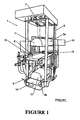
- the vacuum packaging machine includes upper and lower vertically stacked vacuum chambers 3a,3b, which are vertically moveably mounted between columns 5. Mounted adjacent the tops of the columns 5 is a drive mechanism 7 for the vacuum chambers 3a, 3b.
- An electronic control system 8 controls operation of the machine 1, and a keypad/monitor 10 is provided to enable a user to program the control system.
- Each vacuum chamber 3a, 3b includes a bed 9 and a chamber hood 11.
- the beds 9 are synchronously vertically movably mounted between the columns 5, and each chamber hood 11 is vertically moveable relative to the respective bed 9.
- the chamber hoods 11 are moved via any suitable motive device, e.g. pneumatic rams, hydraulic rams or mechanical drive devices.
- Each vacuum chamber has a sealing assembly 15 therein, described below with reference to Figures 3 to 6 .
- the bed 9 of each vacuum chamber includes an internal conveyor 13 to convey packaged product out of the chamber after it has been vacuum sealed, the direction of travel of the conveyor 13 defining a longitudinal direction of the vacuum chamber.
- a conveyor arrangement is provided to feed/unload loaded bags to/from the vacuum chambers.
- the conveyor arrangement includes an infeed conveyor 17 to feed loaded bags into the vacuum chambers.
- An optional outfeed conveyor (not shown) is also provided to remove a sealed loaded bag from the machine following sealing.
- the vacuum chambers are moveable together between a lower position (shown in Figures 1 and 2 ) wherein the upper chamber 3a is adjacent the infeed conveyor 17 for feeding and unloading, and an upper position (not shown) wherein the bed of the lower chamber 3b is adjacent the infeed conveyor 17 for feeding and unloading. While one of the vacuum chambers is in the feeding/unloading position, the other chamber is in an operating position to perform a vacuum sealing operation on the loaded bag contained therein. Therefore, the operating position for the upper vacuum chamber 3a is above the level of the infeed conveyor, while the operating position for the lower vacuum chamber 3b is below the level of the infeed conveyor.
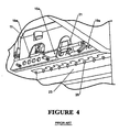
- the sealing assembly 15 in each vacuum chamber includes an upper part 15a and a lower part 15b.
- the sealing assembly 15 extends transversely to the longitudinal direction of the vacuum chamber, and therefore to the direction of travel of loaded bags through the chamber. This enables the loaded bag to be delivered to the vacuum chamber with its unsealed portion trailing, which is the orientation in which the loaded bag would exit from prior bagging/wrapping stations.
- the upper part 15a of the sealing assembly includes a pair of upper spreaders 19a, a heat seal anvil 21, a puncturing device having a plurality of piercing knives (not shown), and a clamping device 23 having a series of clamping pins 25.
- the lower part 15b of the seal assembly includes a pair of lower spreaders 19b which are complementary to the pair of upper spreaders 19a, a heat seal bar 27, and a lower clamp bar 29. It will be appreciated that the anvil could be provided in the lower part 15b of the seal assembly, with the heat seal bar provided in the upper part 15a of the seal assembly.
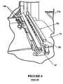
- the spreading operation is as follows.
- the spreaders 19a, 19b are operable to grip and spread the unsealed part of the loaded bag prior to heat sealing.
- the spreaders function in a similar way to those described in US Patent No. 6,877,543 (Stevens ), incorporated herein by reference in its entirety.
- the clamping pins 25 and lower clamp bar 29 (which would generally be made from a resilient material such as rubber) maintain the unsealed portion of the package in the spread configuration, and provide tension on the loaded bag such that it can be pierced.
- the puncturing device When the puncturing device is actuated, the knives (not shown) pierce the package.
- the puncturing device forms small apertures in the loaded bag.
- the trailing unsealed portion of the loaded bag may be located such that it will be clamped under the end wall of the vacuum chamber hood 11 when it is closed.
- the apertures formed by the puncturing device ensure that any air in the loaded bag may still be evacuated if this should occur.
- the heat seal anvil 21 is operable to push against the heat seal bar 27 with the unsealed portion of the loaded bag therebetween, applying a current to the heat seal bar and sealing the loaded bag.
- a suitable cutting device is provided to cut the loaded bag between the heat seal bar 27 and the puncturing device.
- An example of a cutting device is a serrated knife, which is arranged to move downwards from above to shear the loaded bag.
- the belt of the conveyor 13 extends under the lower part of the seal assembly 15b, and around the outer ends of the bed 9 of the vacuum chamber.
- the undersurface of the conveyor belt comprises a smooth surface (relative to a conventional cloth surface), for example a smooth elasticized surface, such that the vacuum chamber can seal over the belt.
- the infeed conveyor 17 has in one embodiment a telescoping portion 17a.
- the telescoping portion 17a extends over the lower part 15b of the seal assembly, and is operated to drop the body of the loaded bag onto the conveyor 13 on the bed 9 of the vacuum chamber.
- the trailing unsealed portion of the loaded bag will remain located on the telescoping portion 17a of the infeed conveyor.
- the telescoping portion 17a is retracted away from the vacuum chamber so that the vacuum chamber can be moved and closed, the trailing unsealed portion of the loaded bag will drop onto the lower part 15b of the seal assembly, so that the unsealed portion can be spread and sealed.
- the seal assembly 15 is relatively low profile to minimize the product drop distance as the telescoping portion 17a of the conveyor is extended into the vacuum chamber.
- FIG. 7 shows a schematic view of an apparatus 30 for use in carrying out the method of the invention.
- the apparatus 30 includes an infeed conveyor 17 having a conveyor belt 32, a bank of light emitting diodes (LED's) 34 positioned beneath conveyor belt 32, and infrared (IR) camera 36, an infrared filter 38, and a camera lens 40.
- the camera, LED's, filter and lens together comprise a sensing apparatus 41.
- the IR camera lens 40 is in one embodiment positioned vertically above the bank of light emitting diodes 34.
- An unsealed bag 42 is shown, loaded with a meat product 46 to form an unsealed loaded bag 43.
- the unsealed loaded bag 43 is in one embodiment advanced on infeed conveyor 17 described hereinabove.
- a commercial example of a conveyor belt 32 useful in connection with the present invention is the VOLTATM FELW-2.0 available from Ammerall Beltech, Inc.
- the belt is a homogeneous urethane belt.
- the belt is routed around the conveyor platen 44 by end rollers 45, at least one of which is motor driven.
- the conveyor platen 44 houses the bank of LED's 34.
- the bank of LED's 34 includes four sets of infrared lights.
- a commercial example of LED's is the LEDIA80X80WTM available from Banner Engineering Corp. 9714 Tenth Avenue North, Minneapolis, Minnesota, USA 55441.
- the IR camera is mounted at a sufficient height, in one embodiment 20 inches above the conveyor belt 32, to view the necessary viewing area in conjunction with the appropriate light filter 38 and camera lens 40.
- a commercial example of an IR camera is PRESENCEPLUSTM P4AR.
- a commercial example of an IR filter is FLT1TM.
- a commercial example of a lens is LCF04TM P4AR. All three are available from Banner Engineering Corp.
- the IR camera can be mounted at any suitable height above the conveyor belt 32, e.g. from 5 inches to 30 inches, 10 to 25 inches, or 15 to 20 inches above conveyor belt 32. The lower limit will be dictated at least in part by the height of the product being packaged, the upper limit by the capabilities of the camera, and the overall packaging environment in which the sensing apparatus is located.
- the vacuum packaging machine 1 would be located downstream from a manual, semi-automatic, or fully automatic bagging machine.
- a fixed input conveyor (not shown) would deliver unsealed loaded bags to the infeed conveyor 17, the loaded bags being oriented such that the unsealed portion of each loaded bag is trailing.
- the product is a meat cut.
- the infeed conveyor 17 activated to place a loaded bag onto the conveyor 13 on the bed of the vacuum chamber 3a.
- the trailing unsealed portion of the loaded bag falls onto the lower part of the seal assembly.
- Sensing apparatus 41 detects the trailing edge of the product 46 in the unsealed loaded bag 43 as it passes a point on the conveyor 17 where it is located between the overhead camera 36 and the LED's 34 positioned beneath conveyor 17. As the trailing edge 49 of product 46 passes the interrogating view of the IR camera and LED's, the infrared light from the LED's comes into view of the interrogating IR camera. At this point, the IR camera effectively detects the trailing edge of the product, and this is communicated to the other parts of the system to trigger the controlled advance of the bagged product to the seal assembly in the vacuum chamber.
- the trailing edge of the product is determined by an internal algorithm in the camera, which converts the IR image that the camera receives to a gray-scale value.
- the gray-scale value is based on a rectangular field of view as defined by the user for each unique application.
- the algorithm looks for the percentage of the gray-scale value to fall below a certain number, which indicates that the trailing edge has been captured within the field of view.
- PLC programmable logic controller
- the determination of the time required to properly position the loaded bag in the vacuum chamber can be done by any suitable means, such as with timers (knowing the speed of the conveyor and the distance of travel required), or by using encoder pulses on the drive motor to track the distance traveled after the trailing edge is captured, knowing the equivalent distance of linear travel per pulse from the encoder.
- the unsealed loaded bag is thus advanced downstream along conveyor 17 and placed inside the open vacuum chamber to a position where the trailing edge 49 of the product inside the loaded bag 43 lies just beyond (i.e. downstream of) the seal assembly 15.
- the hood 11 of the upper vacuum chamber 3a can then be closed.
- the chambers will move to their upper positions, and the lower chamber 3b will be fully depressurized, the chamber then being opened and the packaged product unloaded while the new loaded bag is simultaneously loaded.
- the unsealed portion of the loaded bag is spread by the spreading system.
- the puncturing device is then actuated, such that knives pierce the unsealed portion of the loaded bag while the clamping pins 25 hold it in the spread configuration against the lower clamp bar 29.
- the spreader bars 19 are then released, and the vacuum chamber 3a is evacuated.
- the heat seal anvil 21 then pushes against the heat seal bar 27, heat sealing the package therebetween.
- the cutting device then shears the scrap portion of the loaded bag between the heat seal bar 27 and the puncturing device.
- the anvil 21 is then moved away from the heat seal bar 27.
- the chamber moves to the unloading position and opens, the sealed loaded bag will be released.
- the air curtain and suction are then actuated to remove the scrap from the vacuum chamber.
- a commercial example of a conveyor belt 32 is the VOLTATM FELW-2.0 available from Ammerall Beltech, Inc.
- the belt is a homogeneous urethane belt.
- the belt is routed around the conveyor platen 44.
- the conveyor platen 44 houses the bank of LED's 34.
- the bank of LED's 34 includes four sets of infrared lights.
- a commercial example of LED's is the LEDIA80X80WTM available from Banner Engineering Corp. 9714 Tenth Avenue North, Minneapolis, Minnesota, USA 55441.
- the IR camera is mounted at a sufficient height, in one embodiment 20 inches above the conveyor belt 32, to view the necessary viewing area in conjunction with the appropriate light filter 38 and camera lens 40.
- a commercial example of an IR camera is PRESENCEPLUSTM P4AR.
- a commercial example of an IR filter is FLT1TM.
- a commercial example of a lens is LCF04TM P4AR. All three are available from Banner Engineering Corp.
- Testing was done on a product handling conveyor driven by a three phase AC motor (3450 rpm) coupled to a 10:1 gearbox controlled by a Yaskawa V7TM VFD in open loop vector mode.
- This test used the vision sensor to detect the trailing (upstream) edge of the meat product and stop the conveyor after a fixed time delay that the placed the product under a laser line for measurement.
- the conveyor speed was set to 1 meter/second with an S-curve accelerate/decelerate of 0.4 seconds.
- the stop command for the drive was controlled from the High Speed Counter Module.
- the belt was a food-grade white urethane belt from Volta.
- the infrared LED lighting was placed under the belt directly beneath the vision sensor to enable the vision sensor when product was present. (see Figures 8 and 9 ).
- the vision sensor was placed vertically looking down at the conveyor.
- the Volta belt was transparent to the IR light, allowing the vision sensor to detect the trailing edge of the meat product.
- the meat product on the other hand, blocks the IR light, leaving a silhouette of the meat product visible to the sensor.
- B1 was a printed bag with dimensions of 12" x 20".
- B2 was a clear bag with dimensions of 13.5" x 21 ".
- B3 was a printed bag with dimensions of 12" x 22”.
- B4 was a bag with dimensions of 14" x 24".
- P1 through P4 represent various meat products/meat cuts.
- P1 had the dimensions 17" long x 9" wide x 4.38" high.
- P2 had the dimensions 12.5" long x 8.38" wide x 6.38” high.
- P3 had the dimensions 9.5" long x 7.5" wide x 5.5" high.
- P4 had the dimensions 9" long x 4.88" wide x 5.5" high.
- Thirty samples of each bag/product combination were recorded. The standard deviation and error were calculated from this data. The result was that the error for the entire population was 0.655 inches, or 16.63 mm.
- the product detection test involved seven (7) different bag types, using two (2) different products.
- the product detection system was able to recognize product through all seven bag samples.
- the product detection system required two different system settings, one for standard bags and one for dark colored bags.
- the standard setting applied a typical gain and exposure time, while the dark bag setting involved a high gain and exposure time.
- the following table summarizes the results of the product detection test.
- the test utilized the following components: Item Part Number Banner Vision Sensor P4AR Banner IR Light (x 4) LEDIA80X80W Banner 4 mm lens LCF04 Banner I/O Cable P4C23 Banner IP67 Enclosure P4RE67-P Custom Encl. for IR lights Volta Conveyor Belt FELW-2.0
- test involved running product underneath the product detection sensor and ascertaining if the sensor would correctly identify the end of the product through the bag and typical wrinkles.
- Bag Setting 1 Setting 2 Clear Bag Yes no Boneguard Bag Yes no Small Printed Bag Yes no Large Printed Bag Yes no Red Colored Bag Yes no Gold Metallic Colored Bag Yes no Black Colored Bag No yes
- any suitable bag formulations especially those made from thermoplastic films such as olefinic films with or without oxygen barrier functionality, can be used with benefit in this invention. These films are made by extrusion coating, coextrusion, lamination, or other suitable processes. Especially preferred for many applications are films comprising an outer layer, an intermediate layer, and an inner layer.
- the materials of the outer layer are often chosen for abuse resistance and/or sealability, and can be chosen from any suitable polymeric materials such as polyolefins, especially ethylenic polymers and copolymers, polypropylene, polyesters, polyamides, and the like.
- the inner layer materials often chosen for sealability, can be any of the materials described for the outer layer.
- the intermediate layer materials are often chosen for their barrier qualities (i.e.
- Preferred materials include polyvinylidene chloride polymers and copolymers, ethylene vinyl alcohol copolymer, polyvinyl alcohol, polyamide, polyester, acrylonitrile, and the like. Bags are in one embodiment heat shrinkable, and in one embodiment at least partially crosslinked.
- “Loaded” herein refers to a bag in which a product, such as a meat product, has been placed manually, mechanically, or otherwise. “Loaded” does not necessarily mean “filled”, as conventional bagged meat packages can have some empty voids or spaces within the bag interior even after loading the bag.
- each vacuum chamber having a transverse heat seal assembly in each vacuum chamber enables the loaded bags to be loaded into each chamber with their openings transverse to the longitudinal direction.
- This orientation corresponds to the orientation of the packages as they exit most manual bagging stations or automatic packaging systems, which would generally be upstream of the vacuum packaging machine.
- each vacuum chamber can include a heat seal bar. Additionally, each heat seal assembly may include a heat seal anvil.
- the machine may include vacuum chambers which are arranged generally vertically one above each other
- the machine can be configured to operate one of the vacuum chambers to perform the vacuum sealing operation while another of the vacuum chambers is open for feeding and unloading of loaded bag(s).
- the vacuum packaging machine may include or be in combination with a conveyor arrangement configured to feed and/or unload loaded bags to and/or from the vacuum chambers.
- the conveyor arrangement suitably includes at least one infeed conveyor operable to feed to a selected vacuum chamber at least one loaded bag.
- the heat seal assembly in each vacuum chamber can be located at or adjacent the end of the chamber adjacent the infeed conveyor(s), and the infeed conveyor(s) is/are configured to feed the loaded bag(s) into the chamber with the unsealed portion(s) of the package(s) trailing.
- the infeed conveyor(s) may have a telescoping portion which is operable to telescope over the heat seal assembly or a part of the heat seal assembly in a vacuum chamber to feed the loaded bag(s) into the vacuum chamber such that an unsealed portion of the loaded bag(s) is located over the heat seal assembly or part thereof, and to then retract from the chamber to allow the chamber to close to perform the vacuum sealing operation.
- the infeed conveyor(s) can be moveable relative to the vacuum chambers to enable selective feeding of loaded bags into more than one chamber.
- the vacuum chambers may be moveable relative to the infeed conveyor(s) to enable selective feeding of more than one chamber.
- Each vacuum chamber can include an internal conveyor, which is moveable in the longitudinal direction of the vacuum chamber to expel the product package(s) from the vacuum chamber following a vacuum sealing operation.
- a portion of the internal conveyor may extend under the heat seal assembly or a part of the heat seal assembly in each vacuum chamber.
- the vacuum chambers can each include a vacuum chamber hood and wherein a portion of the internal conveyor in each vacuum chamber extends under the vacuum chamber hood thereof.
- the heat seal assembly or a part thereof may be retractable to enable loaded bags to be moved past the heat seal assembly on the internal conveyor, and the telescoping conveyor may be substantially vertically aligned with the internal chamber conveyor in a loaded bag feeding configuration.
- the conveyor arrangement can include at least one outfeed conveyor operable to unload the loaded bag(s) from a selected vacuum chamber.
- the vacuum chambers may be moveable relative to the outfeed conveyor(s) to enable selective unloading of more than one chamber.
- the conveyor arrangement can be operable to substantially simultaneously load an unsealed loaded bag into a selected vacuum chamber and unload another recently-sealed loaded bag from the selected vacuum chamber.
- the machine can include two vertically-stacked vacuum chambers, an infeed conveyor and an outfeed conveyor, the vacuum chambers being synchronously vertically moveable between a feeding/unloading position adjacent and between the infeed and outfeed conveyor and an operating position spaced from the infeed and outfeed conveyor, the machine being operable such that as one vacuum chamber is performing the vacuum sealing operation, the other vacuum chamber is open for feeding/unloading.
- the machine can further include a puncturing device which is operable to puncture at least one aperture in the loaded bag(s) adjacent the heat seal assembly, so that as each vacuum sealing operation occurs, air is forced out of the package through the punctured aperture(s) prior to heat sealing.
- the puncturing device may comprise a plurality of piercing knives.
- the sealing mechanism may be part of a wrapping or bagging machine.
- the heat seal assembly can include a clamping device and the vacuum sealing operation includes clamping the unsealed part(s) of the loaded bag(s) prior to evacuation and heat sealing.
- the machine can include a cutting device arranged to cut the loaded bag(s) between the heat seal assembly and the puncturing device, and the vacuum sealing operation can include cutting the package(s) following evacuation and heat sealing.
Landscapes
- Engineering & Computer Science (AREA)
- Mechanical Engineering (AREA)
- Chemical & Material Sciences (AREA)
- Dispersion Chemistry (AREA)
- Physics & Mathematics (AREA)
- General Physics & Mathematics (AREA)
- Vacuum Packaging (AREA)
- Package Closures (AREA)
Applications Claiming Priority (2)
| Application Number | Priority Date | Filing Date | Title |
|---|---|---|---|
| US12/156,137 US7891159B2 (en) | 2008-05-30 | 2008-05-30 | Method for positioning a loaded bag in a vacuum chamber |
| PCT/US2009/003203 WO2009145885A1 (en) | 2008-05-30 | 2009-05-26 | Method for positioning a loaded bag in a vacuum chamber |
Publications (2)
| Publication Number | Publication Date |
|---|---|
| EP2296974A1 EP2296974A1 (en) | 2011-03-23 |
| EP2296974B1 true EP2296974B1 (en) | 2011-11-23 |
Family
ID=40929638
Family Applications (1)
| Application Number | Title | Priority Date | Filing Date |
|---|---|---|---|
| EP09755248A Not-in-force EP2296974B1 (en) | 2008-05-30 | 2009-05-26 | Method for positioning a loaded bag in a vacuum chamber |
Country Status (7)
| Country | Link |
|---|---|
| US (1) | US7891159B2 (enExample) |
| EP (1) | EP2296974B1 (enExample) |
| JP (1) | JP5160686B2 (enExample) |
| AT (1) | ATE534579T1 (enExample) |
| AU (1) | AU2009251801B2 (enExample) |
| NZ (1) | NZ589291A (enExample) |
| WO (1) | WO2009145885A1 (enExample) |
Cited By (1)
| Publication number | Priority date | Publication date | Assignee | Title |
|---|---|---|---|---|
| CN104924212A (zh) * | 2014-03-17 | 2015-09-23 | 中国铁道科学研究院铁道建筑研究所 | 一种检测钢轨铣磨车刀粒精度的装置 |
Families Citing this family (18)
| Publication number | Priority date | Publication date | Assignee | Title |
|---|---|---|---|---|
| US9676506B2 (en) * | 2012-10-19 | 2017-06-13 | Sunbeam Products, Inc. | Vacuum packaging and sealing appliance with liquid detection |
| DE102013104666A1 (de) * | 2013-05-07 | 2014-11-13 | Krones Ag | Vorrichtung und Verfahren zum Herstellen von Behältniszusammenstellungen |
| US20140360134A1 (en) * | 2013-06-11 | 2014-12-11 | Cryovac, Inc. | Ferris-Wheel Type Vacuum Packaging System And Method |
| EP2829479A1 (en) * | 2013-07-23 | 2015-01-28 | Cryovac, Inc. | Packaging apparatus comprising actuator and method of operating packaging apparatus |
| EP3063004B1 (en) | 2013-11-01 | 2018-02-28 | Cryovac, Inc. | Delamination-resistant heat-shrinkable multilayer oxygen barrier film containing polyester |
| EP2907760B1 (en) | 2014-02-14 | 2016-06-08 | Ulma Packaging Technological Center, S.Coop. | Method and machine for vacuum packaging a product |
| US20160047786A1 (en) * | 2014-08-12 | 2016-02-18 | Sunbeam Products, Inc. | Food Storage Appliance with Moisture Sensor |
| US10029407B2 (en) | 2014-12-04 | 2018-07-24 | Big Heart Pet, Inc. | Apparatus, processes, and systems for heat sealing |
| US20160176548A1 (en) * | 2014-12-23 | 2016-06-23 | Frito-Lay North America, Inc. | Method and apparatus for a product settler |
| AR104246A1 (es) * | 2015-04-14 | 2017-07-05 | Cryovac Inc | Método de colocar y sellar una bolsa en una cámara de vacío, aparato de colocación de la bolsa, y método de fabricación de una bolsa de parche |
| EP3800134A1 (en) * | 2015-09-25 | 2021-04-07 | Cryovac, LLC | Apparatus and method for vacuumizing and sealing a package |
| ITUA20161736A1 (it) * | 2016-03-16 | 2017-09-16 | Microtec Srl | Apparecchiatura per l’esecuzione di una indagine non distruttiva su tavole di legno o simili oggetti |
| CN110342403B (zh) * | 2019-07-01 | 2020-06-09 | 中冶宝钢技术服务有限公司 | 一种钢卷吊运方法及吊运系统 |
| CN111572859B (zh) * | 2020-05-21 | 2021-08-03 | 江西万村泉食品有限公司 | 一种速食品真空包装方法 |
| CN115092450B (zh) * | 2022-08-11 | 2023-06-20 | 桂林航天工业学院 | 一种真空封口机 |
| CN115339684A (zh) * | 2022-10-20 | 2022-11-15 | 山东创新精密科技有限公司 | 铝型材套袋后的吸气机构 |
| JP2024076791A (ja) * | 2022-11-25 | 2024-06-06 | Pacraft株式会社 | 包装方法及び包装装置 |
| CN115821868B (zh) * | 2022-12-08 | 2024-07-23 | 西南科技大学 | 一种鱼类辅助洄游装置 |
Family Cites Families (35)
| Publication number | Priority date | Publication date | Assignee | Title |
|---|---|---|---|---|
| JPS5159593A (en) * | 1974-11-21 | 1976-05-24 | Furukawa Seisakusho Kk | Shinkuhosohoho oyobisono shinkuhosoki |
| US4147930A (en) | 1975-03-20 | 1979-04-03 | U.S. Philips Corporation | Object location detector |
| US4085563A (en) * | 1977-01-31 | 1978-04-25 | Campbell Soup Company | Cookie dispensing apparatus |
| JPS55132904A (en) | 1979-04-05 | 1980-10-16 | Fuji Electric Co Ltd | Shape inspection system |
| JPS601210B2 (ja) | 1981-05-23 | 1985-01-12 | 株式会社古川製作所 | 自動包装機械 |
| DE3411186A1 (de) * | 1984-03-27 | 1985-10-10 | Battelle-Institut E.V., 6000 Frankfurt | Vorrichtung zum automatischen ueberpruefen und erkennen von objekten |
| US4580393A (en) | 1984-04-11 | 1986-04-08 | Furukawa Mfg. Co., Ltd. | Packing apparatus |
| US5313766A (en) * | 1987-02-23 | 1994-05-24 | Awax S.R.L. | Method and apparatus for on demand manufacturing of custom-sized bags conforming to the volume of articles received therein at a check-out counter |
| US4882498A (en) * | 1987-10-09 | 1989-11-21 | Pressco, Inc. | Pulsed-array video inspection lighting system |
| IT1215809B (it) * | 1988-02-05 | 1990-02-22 | Awax Srl | Su misura conformi al volume degli cassa di supermercato completamente articoli accolti in essi. self service incorporante un apparecchio integrato per fabbricare su richiesta sacchetti |
| JPH0767923B2 (ja) * | 1990-06-20 | 1995-07-26 | 株式会社フジキカイ | 横型製袋充填包装機 |
| US5365084A (en) | 1991-02-20 | 1994-11-15 | Pressco Technology, Inc. | Video inspection system employing multiple spectrum LED illumination |
| US5165218A (en) * | 1991-06-20 | 1992-11-24 | Callahan Jr Bernard C | Automatic sorting, stacking and packaging apparatus and method |
| DE4131664A1 (de) | 1991-09-23 | 1993-03-25 | Rieter Ingolstadt Spinnerei | Verfahren und vorrichtung zum erfassen von garnfehlern |
| US5280170A (en) * | 1992-12-22 | 1994-01-18 | Emhart Glass Machinery Investments Inc. | Machine for inspecting the shape of a container having a two dimensional camera for viewing the shadow of the projection of the container |
| JP2801530B2 (ja) * | 1994-08-17 | 1998-09-21 | 株式会社フジキカイ | 横型製袋充填包装機及びその制御方法 |
| JP3405424B2 (ja) * | 1994-12-19 | 2003-05-12 | 茨木精機株式会社 | 真空包装装置 |
| IT1276671B1 (it) * | 1995-04-06 | 1997-11-03 | Grace W R & Co | Macchina di confezionamento automatica |
| AU693034B2 (en) * | 1995-06-30 | 1998-06-18 | Kliklok Corporation | Improved transitional product flow and adaptive control |
| US5646724A (en) | 1995-08-18 | 1997-07-08 | Candid Logic, Inc. | Threaded parts inspection device |
| JPH09201886A (ja) * | 1996-01-29 | 1997-08-05 | Totani Giken Kogyo Kk | 製袋機の袋切断装置 |
| US5810795A (en) * | 1996-05-13 | 1998-09-22 | Westwood; Joseph R. | Hyperbaric device with secondary pressure zone |
| US5799465A (en) * | 1996-07-12 | 1998-09-01 | Optima Corporation | Bag filling station |
| US6269609B2 (en) * | 1999-06-15 | 2001-08-07 | Quad/Graphics, Inc. | Apparatus for selective wrapping of products and a method thereof |
| US6384421B1 (en) | 1999-10-07 | 2002-05-07 | Logical Systems Incorporated | Vision system for industrial parts |
| US6490846B2 (en) * | 2000-04-21 | 2002-12-10 | Robert G. Koppe | Opening arrangement for zipper-type pouches for continuous motion pouching machinery |
| US6542235B1 (en) | 2000-04-28 | 2003-04-01 | Lakeshore Vision & Robotics, L.L.C. | System and method of three-dimensional inspection of circular parts |
| AUPQ910600A0 (en) | 2000-07-31 | 2000-08-24 | Cryovac Australia Pty Ltd | Sealing assembly |
| AT4889U1 (de) * | 2000-11-07 | 2001-12-27 | Binder Co Ag | Diodenlichtquelle für eine zeilenkamera |
| US6907711B2 (en) * | 2001-07-09 | 2005-06-21 | Fuji Photo Film Co., Ltd. | Sheet package producing system, sheet handling device, and fillet folding device |
| ATE478805T1 (de) | 2002-02-27 | 2010-09-15 | Sealed Air New Zealand | Vakuumverpackungsmaschine |
| JP2006510554A (ja) * | 2002-12-20 | 2006-03-30 | シールド・エア(エヌ・ゼツト)リミテツド | 複数の製品を有する製品パッケージのための真空包装機 |
| US7007443B2 (en) * | 2003-06-27 | 2006-03-07 | Forhealth Technologies, Inc. | System and method for bandoliering syringes |
| WO2005100961A2 (en) | 2004-04-19 | 2005-10-27 | Phoseon Technology, Inc. | Imaging semiconductor strucutures using solid state illumination |
| US20060244954A1 (en) | 2005-03-29 | 2006-11-02 | Daley Wayne D | System and method for inspecting packaging quality of a packaged food product |
-
2008
- 2008-05-30 US US12/156,137 patent/US7891159B2/en active Active
-
2009
- 2009-05-26 NZ NZ589291A patent/NZ589291A/xx not_active IP Right Cessation
- 2009-05-26 EP EP09755248A patent/EP2296974B1/en not_active Not-in-force
- 2009-05-26 JP JP2011511624A patent/JP5160686B2/ja not_active Expired - Fee Related
- 2009-05-26 AT AT09755248T patent/ATE534579T1/de active
- 2009-05-26 AU AU2009251801A patent/AU2009251801B2/en not_active Ceased
- 2009-05-26 WO PCT/US2009/003203 patent/WO2009145885A1/en not_active Ceased
Cited By (1)
| Publication number | Priority date | Publication date | Assignee | Title |
|---|---|---|---|---|
| CN104924212A (zh) * | 2014-03-17 | 2015-09-23 | 中国铁道科学研究院铁道建筑研究所 | 一种检测钢轨铣磨车刀粒精度的装置 |
Also Published As
| Publication number | Publication date |
|---|---|
| NZ589291A (en) | 2013-04-26 |
| JP5160686B2 (ja) | 2013-03-13 |
| ATE534579T1 (de) | 2011-12-15 |
| JP2011521858A (ja) | 2011-07-28 |
| AU2009251801A1 (en) | 2009-12-03 |
| WO2009145885A1 (en) | 2009-12-03 |
| EP2296974A1 (en) | 2011-03-23 |
| US20090293430A1 (en) | 2009-12-03 |
| AU2009251801B2 (en) | 2013-04-18 |
| US7891159B2 (en) | 2011-02-22 |
Similar Documents
| Publication | Publication Date | Title |
|---|---|---|
| EP2296974B1 (en) | Method for positioning a loaded bag in a vacuum chamber | |
| AU2021200658B2 (en) | Apparatus and method for vacuumizing and sealing a package | |
| EP0819081B1 (en) | Method and apparatus for automatically packaging a food or non food product | |
| AU2003288835B2 (en) | Vacuum packaging machine for product packages with multiple products | |
| EP3283382B1 (en) | Method of positioning and sealing a bag in a vacuum chamber, bag positioning and sealing apparatus | |
| NZ780448B2 (en) | Apparatus and method for vacuumizing and sealing a package | |
| NZ780448A (en) | Apparatus and method for vacuumizing and sealing a package | |
| NZ524458A (en) | Vacuum packaging machine for product packages with multiple products |
Legal Events
| Date | Code | Title | Description |
|---|---|---|---|
| PUAI | Public reference made under article 153(3) epc to a published international application that has entered the european phase |
Free format text: ORIGINAL CODE: 0009012 |
|
| 17P | Request for examination filed |
Effective date: 20101112 |
|
| AK | Designated contracting states |
Kind code of ref document: A1 Designated state(s): AT BE BG CH CY CZ DE DK EE ES FI FR GB GR HR HU IE IS IT LI LT LU LV MC MK MT NL NO PL PT RO SE SI SK TR |
|
| AX | Request for extension of the european patent |
Extension state: AL BA RS |
|
| GRAP | Despatch of communication of intention to grant a patent |
Free format text: ORIGINAL CODE: EPIDOSNIGR1 |
|
| DAX | Request for extension of the european patent (deleted) | ||
| GRAS | Grant fee paid |
Free format text: ORIGINAL CODE: EPIDOSNIGR3 |
|
| GRAA | (expected) grant |
Free format text: ORIGINAL CODE: 0009210 |
|
| RIN1 | Information on inventor provided before grant (corrected) |
Inventor name: MCDONALD, GREG, E. Inventor name: PAINTER, MAX, C. Inventor name: WORKMAN, WAYNE, T. Inventor name: IOCCO, JEFFREY, R. |
|
| AK | Designated contracting states |
Kind code of ref document: B1 Designated state(s): AT BE BG CH CY CZ DE DK EE ES FI FR GB GR HR HU IE IS IT LI LT LU LV MC MK MT NL NO PL PT RO SE SI SK TR |
|
| REG | Reference to a national code |
Ref country code: GB Ref legal event code: FG4D |
|
| REG | Reference to a national code |
Ref country code: CH Ref legal event code: EP |
|
| REG | Reference to a national code |
Ref country code: IE Ref legal event code: FG4D |
|
| REG | Reference to a national code |
Ref country code: DE Ref legal event code: R096 Ref document number: 602009003851 Country of ref document: DE Effective date: 20120209 |
|
| REG | Reference to a national code |
Ref country code: NL Ref legal event code: VDEP Effective date: 20111123 |
|
| LTIE | Lt: invalidation of european patent or patent extension |
Effective date: 20111123 |
|
| PG25 | Lapsed in a contracting state [announced via postgrant information from national office to epo] |
Ref country code: LT Free format text: LAPSE BECAUSE OF FAILURE TO SUBMIT A TRANSLATION OF THE DESCRIPTION OR TO PAY THE FEE WITHIN THE PRESCRIBED TIME-LIMIT Effective date: 20111123 Ref country code: NO Free format text: LAPSE BECAUSE OF FAILURE TO SUBMIT A TRANSLATION OF THE DESCRIPTION OR TO PAY THE FEE WITHIN THE PRESCRIBED TIME-LIMIT Effective date: 20120223 Ref country code: IS Free format text: LAPSE BECAUSE OF FAILURE TO SUBMIT A TRANSLATION OF THE DESCRIPTION OR TO PAY THE FEE WITHIN THE PRESCRIBED TIME-LIMIT Effective date: 20120323 |
|
| PG25 | Lapsed in a contracting state [announced via postgrant information from national office to epo] |
Ref country code: LV Free format text: LAPSE BECAUSE OF FAILURE TO SUBMIT A TRANSLATION OF THE DESCRIPTION OR TO PAY THE FEE WITHIN THE PRESCRIBED TIME-LIMIT Effective date: 20111123 Ref country code: GR Free format text: LAPSE BECAUSE OF FAILURE TO SUBMIT A TRANSLATION OF THE DESCRIPTION OR TO PAY THE FEE WITHIN THE PRESCRIBED TIME-LIMIT Effective date: 20120224 Ref country code: SE Free format text: LAPSE BECAUSE OF FAILURE TO SUBMIT A TRANSLATION OF THE DESCRIPTION OR TO PAY THE FEE WITHIN THE PRESCRIBED TIME-LIMIT Effective date: 20111123 Ref country code: PT Free format text: LAPSE BECAUSE OF FAILURE TO SUBMIT A TRANSLATION OF THE DESCRIPTION OR TO PAY THE FEE WITHIN THE PRESCRIBED TIME-LIMIT Effective date: 20120323 Ref country code: SI Free format text: LAPSE BECAUSE OF FAILURE TO SUBMIT A TRANSLATION OF THE DESCRIPTION OR TO PAY THE FEE WITHIN THE PRESCRIBED TIME-LIMIT Effective date: 20111123 Ref country code: NL Free format text: LAPSE BECAUSE OF FAILURE TO SUBMIT A TRANSLATION OF THE DESCRIPTION OR TO PAY THE FEE WITHIN THE PRESCRIBED TIME-LIMIT Effective date: 20111123 Ref country code: BE Free format text: LAPSE BECAUSE OF FAILURE TO SUBMIT A TRANSLATION OF THE DESCRIPTION OR TO PAY THE FEE WITHIN THE PRESCRIBED TIME-LIMIT Effective date: 20111123 Ref country code: HR Free format text: LAPSE BECAUSE OF FAILURE TO SUBMIT A TRANSLATION OF THE DESCRIPTION OR TO PAY THE FEE WITHIN THE PRESCRIBED TIME-LIMIT Effective date: 20111123 |
|
| PG25 | Lapsed in a contracting state [announced via postgrant information from national office to epo] |
Ref country code: CY Free format text: LAPSE BECAUSE OF FAILURE TO SUBMIT A TRANSLATION OF THE DESCRIPTION OR TO PAY THE FEE WITHIN THE PRESCRIBED TIME-LIMIT Effective date: 20111123 |
|
| PG25 | Lapsed in a contracting state [announced via postgrant information from national office to epo] |
Ref country code: DK Free format text: LAPSE BECAUSE OF FAILURE TO SUBMIT A TRANSLATION OF THE DESCRIPTION OR TO PAY THE FEE WITHIN THE PRESCRIBED TIME-LIMIT Effective date: 20111123 Ref country code: CZ Free format text: LAPSE BECAUSE OF FAILURE TO SUBMIT A TRANSLATION OF THE DESCRIPTION OR TO PAY THE FEE WITHIN THE PRESCRIBED TIME-LIMIT Effective date: 20111123 Ref country code: EE Free format text: LAPSE BECAUSE OF FAILURE TO SUBMIT A TRANSLATION OF THE DESCRIPTION OR TO PAY THE FEE WITHIN THE PRESCRIBED TIME-LIMIT Effective date: 20111123 Ref country code: BG Free format text: LAPSE BECAUSE OF FAILURE TO SUBMIT A TRANSLATION OF THE DESCRIPTION OR TO PAY THE FEE WITHIN THE PRESCRIBED TIME-LIMIT Effective date: 20120223 Ref country code: SK Free format text: LAPSE BECAUSE OF FAILURE TO SUBMIT A TRANSLATION OF THE DESCRIPTION OR TO PAY THE FEE WITHIN THE PRESCRIBED TIME-LIMIT Effective date: 20111123 |
|
| PG25 | Lapsed in a contracting state [announced via postgrant information from national office to epo] |
Ref country code: IT Free format text: LAPSE BECAUSE OF FAILURE TO SUBMIT A TRANSLATION OF THE DESCRIPTION OR TO PAY THE FEE WITHIN THE PRESCRIBED TIME-LIMIT Effective date: 20111123 Ref country code: RO Free format text: LAPSE BECAUSE OF FAILURE TO SUBMIT A TRANSLATION OF THE DESCRIPTION OR TO PAY THE FEE WITHIN THE PRESCRIBED TIME-LIMIT Effective date: 20111123 Ref country code: PL Free format text: LAPSE BECAUSE OF FAILURE TO SUBMIT A TRANSLATION OF THE DESCRIPTION OR TO PAY THE FEE WITHIN THE PRESCRIBED TIME-LIMIT Effective date: 20111123 |
|
| REG | Reference to a national code |
Ref country code: AT Ref legal event code: MK05 Ref document number: 534579 Country of ref document: AT Kind code of ref document: T Effective date: 20111123 |
|
| PLBE | No opposition filed within time limit |
Free format text: ORIGINAL CODE: 0009261 |
|
| STAA | Information on the status of an ep patent application or granted ep patent |
Free format text: STATUS: NO OPPOSITION FILED WITHIN TIME LIMIT |
|
| 26N | No opposition filed |
Effective date: 20120824 |
|
| REG | Reference to a national code |
Ref country code: DE Ref legal event code: R097 Ref document number: 602009003851 Country of ref document: DE Effective date: 20120824 |
|
| PG25 | Lapsed in a contracting state [announced via postgrant information from national office to epo] |
Ref country code: MC Free format text: LAPSE BECAUSE OF NON-PAYMENT OF DUE FEES Effective date: 20120531 |
|
| PG25 | Lapsed in a contracting state [announced via postgrant information from national office to epo] |
Ref country code: AT Free format text: LAPSE BECAUSE OF FAILURE TO SUBMIT A TRANSLATION OF THE DESCRIPTION OR TO PAY THE FEE WITHIN THE PRESCRIBED TIME-LIMIT Effective date: 20111123 |
|
| REG | Reference to a national code |
Ref country code: IE Ref legal event code: MM4A |
|
| PG25 | Lapsed in a contracting state [announced via postgrant information from national office to epo] |
Ref country code: MK Free format text: LAPSE BECAUSE OF FAILURE TO SUBMIT A TRANSLATION OF THE DESCRIPTION OR TO PAY THE FEE WITHIN THE PRESCRIBED TIME-LIMIT Effective date: 20111123 |
|
| PG25 | Lapsed in a contracting state [announced via postgrant information from national office to epo] |
Ref country code: ES Free format text: LAPSE BECAUSE OF FAILURE TO SUBMIT A TRANSLATION OF THE DESCRIPTION OR TO PAY THE FEE WITHIN THE PRESCRIBED TIME-LIMIT Effective date: 20120305 Ref country code: IE Free format text: LAPSE BECAUSE OF NON-PAYMENT OF DUE FEES Effective date: 20120526 |
|
| PG25 | Lapsed in a contracting state [announced via postgrant information from national office to epo] |
Ref country code: FI Free format text: LAPSE BECAUSE OF FAILURE TO SUBMIT A TRANSLATION OF THE DESCRIPTION OR TO PAY THE FEE WITHIN THE PRESCRIBED TIME-LIMIT Effective date: 20111123 |
|
| PG25 | Lapsed in a contracting state [announced via postgrant information from national office to epo] |
Ref country code: MT Free format text: LAPSE BECAUSE OF FAILURE TO SUBMIT A TRANSLATION OF THE DESCRIPTION OR TO PAY THE FEE WITHIN THE PRESCRIBED TIME-LIMIT Effective date: 20111123 |
|
| REG | Reference to a national code |
Ref country code: CH Ref legal event code: PL |
|
| PG25 | Lapsed in a contracting state [announced via postgrant information from national office to epo] |
Ref country code: LI Free format text: LAPSE BECAUSE OF NON-PAYMENT OF DUE FEES Effective date: 20130531 Ref country code: CH Free format text: LAPSE BECAUSE OF NON-PAYMENT OF DUE FEES Effective date: 20130531 |
|
| PG25 | Lapsed in a contracting state [announced via postgrant information from national office to epo] |
Ref country code: TR Free format text: LAPSE BECAUSE OF FAILURE TO SUBMIT A TRANSLATION OF THE DESCRIPTION OR TO PAY THE FEE WITHIN THE PRESCRIBED TIME-LIMIT Effective date: 20111123 |
|
| PG25 | Lapsed in a contracting state [announced via postgrant information from national office to epo] |
Ref country code: LU Free format text: LAPSE BECAUSE OF NON-PAYMENT OF DUE FEES Effective date: 20120526 |
|
| PG25 | Lapsed in a contracting state [announced via postgrant information from national office to epo] |
Ref country code: HU Free format text: LAPSE BECAUSE OF FAILURE TO SUBMIT A TRANSLATION OF THE DESCRIPTION OR TO PAY THE FEE WITHIN THE PRESCRIBED TIME-LIMIT Effective date: 20090526 |
|
| REG | Reference to a national code |
Ref country code: FR Ref legal event code: PLFP Year of fee payment: 8 |
|
| REG | Reference to a national code |
Ref country code: FR Ref legal event code: PLFP Year of fee payment: 9 |
|
| REG | Reference to a national code |
Ref country code: FR Ref legal event code: PLFP Year of fee payment: 10 |
|
| PGFP | Annual fee paid to national office [announced via postgrant information from national office to epo] |
Ref country code: DE Payment date: 20190530 Year of fee payment: 11 |
|
| PGFP | Annual fee paid to national office [announced via postgrant information from national office to epo] |
Ref country code: GB Payment date: 20190528 Year of fee payment: 11 |
|
| REG | Reference to a national code |
Ref country code: DE Ref legal event code: R119 Ref document number: 602009003851 Country of ref document: DE |
|
| GBPC | Gb: european patent ceased through non-payment of renewal fee |
Effective date: 20200526 |
|
| PG25 | Lapsed in a contracting state [announced via postgrant information from national office to epo] |
Ref country code: GB Free format text: LAPSE BECAUSE OF NON-PAYMENT OF DUE FEES Effective date: 20200526 |
|
| PG25 | Lapsed in a contracting state [announced via postgrant information from national office to epo] |
Ref country code: DE Free format text: LAPSE BECAUSE OF NON-PAYMENT OF DUE FEES Effective date: 20201201 |
|
| P01 | Opt-out of the competence of the unified patent court (upc) registered |
Effective date: 20230425 |
|
| PGFP | Annual fee paid to national office [announced via postgrant information from national office to epo] |
Ref country code: FR Payment date: 20230525 Year of fee payment: 15 |
|
| PG25 | Lapsed in a contracting state [announced via postgrant information from national office to epo] |
Ref country code: FR Free format text: LAPSE BECAUSE OF NON-PAYMENT OF DUE FEES Effective date: 20240531 |