EP2296846B1 - Mehrspindel-werkzeugmaschine - Google Patents
Mehrspindel-werkzeugmaschine Download PDFInfo
- Publication number
- EP2296846B1 EP2296846B1 EP09719043A EP09719043A EP2296846B1 EP 2296846 B1 EP2296846 B1 EP 2296846B1 EP 09719043 A EP09719043 A EP 09719043A EP 09719043 A EP09719043 A EP 09719043A EP 2296846 B1 EP2296846 B1 EP 2296846B1
- Authority
- EP
- European Patent Office
- Prior art keywords
- item
- worktable
- frontal face
- machine tool
- machining
- Prior art date
- Legal status (The legal status is an assumption and is not a legal conclusion. Google has not performed a legal analysis and makes no representation as to the accuracy of the status listed.)
- Active
Links
- 238000003754 machining Methods 0.000 claims abstract description 30
- 238000000034 method Methods 0.000 claims description 4
- 238000007514 turning Methods 0.000 description 10
- 238000005553 drilling Methods 0.000 description 2
- 238000010008 shearing Methods 0.000 description 2
- 230000000903 blocking effect Effects 0.000 description 1
- 239000000969 carrier Substances 0.000 description 1
- ZPUCINDJVBIVPJ-LJISPDSOSA-N cocaine Chemical compound O([C@H]1C[C@@H]2CC[C@@H](N2C)[C@H]1C(=O)OC)C(=O)C1=CC=CC=C1 ZPUCINDJVBIVPJ-LJISPDSOSA-N 0.000 description 1
- 238000003801 milling Methods 0.000 description 1
- 210000000056 organ Anatomy 0.000 description 1
- 230000010355 oscillation Effects 0.000 description 1
Images
Classifications
-
- B—PERFORMING OPERATIONS; TRANSPORTING
- B23—MACHINE TOOLS; METAL-WORKING NOT OTHERWISE PROVIDED FOR
- B23Q—DETAILS, COMPONENTS, OR ACCESSORIES FOR MACHINE TOOLS, e.g. ARRANGEMENTS FOR COPYING OR CONTROLLING; MACHINE TOOLS IN GENERAL CHARACTERISED BY THE CONSTRUCTION OF PARTICULAR DETAILS OR COMPONENTS; COMBINATIONS OR ASSOCIATIONS OF METAL-WORKING MACHINES, NOT DIRECTED TO A PARTICULAR RESULT
- B23Q39/00—Metal-working machines incorporating a plurality of sub-assemblies, each capable of performing a metal-working operation
- B23Q39/04—Metal-working machines incorporating a plurality of sub-assemblies, each capable of performing a metal-working operation the sub-assemblies being arranged to operate simultaneously at different stations, e.g. with an annular work-table moved in steps
- B23Q39/042—Metal-working machines incorporating a plurality of sub-assemblies, each capable of performing a metal-working operation the sub-assemblies being arranged to operate simultaneously at different stations, e.g. with an annular work-table moved in steps with circular arrangement of the sub-assemblies
- B23Q39/044—Metal-working machines incorporating a plurality of sub-assemblies, each capable of performing a metal-working operation the sub-assemblies being arranged to operate simultaneously at different stations, e.g. with an annular work-table moved in steps with circular arrangement of the sub-assemblies having at least one tool station cooperating with each work holder, e.g. multi-spindle lathes
-
- B—PERFORMING OPERATIONS; TRANSPORTING
- B23—MACHINE TOOLS; METAL-WORKING NOT OTHERWISE PROVIDED FOR
- B23Q—DETAILS, COMPONENTS, OR ACCESSORIES FOR MACHINE TOOLS, e.g. ARRANGEMENTS FOR COPYING OR CONTROLLING; MACHINE TOOLS IN GENERAL CHARACTERISED BY THE CONSTRUCTION OF PARTICULAR DETAILS OR COMPONENTS; COMBINATIONS OR ASSOCIATIONS OF METAL-WORKING MACHINES, NOT DIRECTED TO A PARTICULAR RESULT
- B23Q7/00—Arrangements for handling work specially combined with or arranged in, or specially adapted for use in connection with, machine tools, e.g. for conveying, loading, positioning, discharging, sorting
- B23Q7/02—Arrangements for handling work specially combined with or arranged in, or specially adapted for use in connection with, machine tools, e.g. for conveying, loading, positioning, discharging, sorting by means of drums or rotating tables or discs
Definitions
- This invention concerns in general machine tools with multiple worktables, and refers in particular to an innovative multi-spindle machine tool for machining items in rotation.
- machine tools with a transfer machine configuration are prepared for machining fixed items, that is to say not turning. They basically comprise, in the area of a support base, a worktable turning intermittently around an axis and equipped with gripping means, such as clamps or vices, to hold each item during machining, and one or more tool operating units rotating in a number of work stations provided in association with the worktable.
- Each rough item can be prepared as an individual element or achieved by shearing it in the form of a cut down size from a continuous bar on loading it into a respective clamp of the worktable.
- each item follows a set course, carried by the worktable and transferred in succession in each of the work stations for the specific operation to be carried out according to a programmed cycle, starting from a loading station up to a downloading station of the item.
- the machine tools in the configuration of multi-spindle lathes have always been provided for machining items in rotations. They have in this case a spindle holder drum which is equipped with several parallel spindles, each one designed to receive and rotate an item, or a bar, and which turn intermittently around an axis to carry each item, or bar, in line with a succession of work stations in which turning carriages with fixed and, sometimes, also rotating tools operate.
- a first spindle-holder drum is equipped with a number of rotatable spindles
- the second spindle-holder drum is equipped with a number of so-called counter spindles, also rotatable, facing towards the spindles of the first spindle-holder drum
- the machining carriages are placed and operating between the two drums and carried by respective turret so that they can access and work the items carried both by the spindles and counter spindles on board the two parallel drums.
- the two spindle carrier drums tend also to increase the complexity and dimensions of these machine tools and furthermore, in order for the turning carriages to be able to machine the items they find themselves mounted on protruding turrets, that is to say susceptible to increased oscillations/deviations under force, that can also reflect negatively on the precision of the machining to be carried out.
- EP-A-1203634 is representative of the state of the art, as well. It concerns a transfer machine corresponding to the preamble of claim 1, in particular provided for turning operations starting from the shearing of items out of a bar and supporting the item to be machined time by time between two opposite spindles in a single work station.
- the objective of this invention is on the other hand to propose an innovative machine tool similar to a multi-spindle lathe for multiple machining of rotating items, but advantageously structured like a transfer machine and equipped to receive and be able to machine rotating items at the same time on two opposite fronts of a single turning worktable with operating units positioned on opposite sides of said table.
- a multi-spindle machine tool according to the preamble of claim 1 and substantially characterized by the inclusion of a first line of rotating item gripper devices on one face of the worktable, a second line of rotating item gripper devices on the opposite face of the worktable, and operating units mounted on the basement in association respectively to the first and second line of rotating item gripper devices and at least one manipulator to pick up and transfer each item from at least one rotating device on the first frontal face and at least one rotating device on the second frontal face of the worktable.
- each item gripper device can be in the form of a self-centring spindle or gripper, controlled and rotating continuously to cause the item to turn with regard to the tools of the operating units.
- the machine tool proposed here has the advantage, even in the presence of a single worktable, of being able to receive and machine each item completely in all its parts: in a first position on one face of the table and then, subject to transfer of each item, in a second position on the opposite face of the same table, access being available from time to time to the portions of each item not blocked in the gripper devices.
- this machine cannot directly machine the bar, but a cut down size of the bar, which can be positioned outside the machine or a cutout of a bar in a work station of the machine itself.
- the machine tool proposed here by having a single worktable it has the advantage of requiring a single indexing system and, furthermore, the operating units no longer need to be carried by projecting turrets, but can be rigidly fixed to the machine bed, therefore in firmer conditions, and conveniently oriented with regard to the items which are from time to time on one or the other face of the worktable.
- the machine tool proposed here by having a single worktable it has the advantage of requiring a single indexing system and, furthermore, the operating units no longer need to be carried by projecting turrets, but can be rigidly fixed to the machine bed, therefore in firmer conditions, and conveniently oriented with regard to the items which are from time to time on one or the other face of the worktable.
- the machine tool proposed here by having a single worktable it has the advantage of requiring a single indexing system and, furthermore, the operating units no longer need to be carried by projecting turrets, but can be rigidly fixed to the machine bed, therefore in firmer conditions, and conveniently
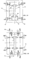
- reference 11 indicates representatively the bed of the machine tool that supports a worktable 12 and, with regard to the latter, a number of operating units for drilling and turning 13, 13' positioned in several work stations at equal angular distances, numbered in succession from for example 1 to 5.
- the worktable 12 è controlled and subject to intermittent rotations around an axis 14. It presents a first frontal face 15 and a second frontal face 15', at right angles to the rotation axis and facing in opposite directions one from the other, and it is equipped with a first line of rotating gripper devices 16 on its first frontal face 15 and with a second line of rotating gripper devices 16' on the second frontal face 15'.
- Said gripper devices 16, 16' can be made up of self-centring spindles or rotating grippers, and even if oriented in opposite directions, each gripper device on a face 15 is preferably coaxial to the corresponding gripper device 16' on the other frontal face 15' of the worktable 12 ( Figs. 1A, 1B ) so that every two pair of organs can be rotated and governed to be blocked and released by the same control system.
- all the gripper devices 16, 16' are parallel to the rotation axis 14 of the worktable, and the work station sequence on the side of the first frontal face 15 of the worktable correspond to the same number of workstations on the side of the second frontal face of said worktable. And therefore, all the gripper devices 16, 16' on the two opposite faces 15, 15' of the worktable are analogically distanced to the work positions 1 - 5 so as to be conducted in sequence and positioned in line with each work station following the intermittent rotation of said worktable 12.
- the gripper devices 16 of the first line face towards some operating units 13, whereas the gripper devices 16' in the second line face towards other operating units 13'.
- the operating units are rigidly supported on the bed 11 of the machine and each one of them will be equipped with at least one tool depending on the work to be carried out:
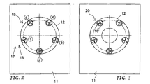
- the machine tool has a loading station 17 with start out items, that coincide with the first work station 1 and which is placed on the side of the first frontal face 15 of the worktable 12 ( Fig. 2 ).
- Each start out item can be prepared as an element on its own or made up of a cut down size blanked from time to time from a continuous bar directly in the machine.
- a feeder 18 is provided to work in association with the worktable 12, to forward step by step the continuous bar, and which is also equipped with a shears to shear a cut down size each time from the bar after the end of the latter has been blocked in a gripper device 16 which is in line with the loading station.
- the work stations from 2 to 5 are provided with operating units 13 to carry out in sequence the initial machining on the part of each item protruding from the relative gripper device 16.
- a final work station in association with the worktable is provided at least one manipulating device 19 set up and managed to grip and reposition each item in a gripper device 16' on the opposite face of the face of the worktable.
- the second face 15' of the worktable ( Fig. 3 ) has a similar prearrangement of the operating units 13' in relation to the gripper devices 16', to carry out in sequence the second machining on the parts of each item protruding from the relative gripper device 16', until a final download station 20 is reached including a download manipulator to evacuate every finished item.
- the gripper devices 16 on the first face of the worktable are prepared to grip a part of the initial rough item, whereas the gripper devices 16' on the other face of the worktable are prepared to grip the item in another position and with a different direction.
- the start out items are blocked in the rotating gripper devices on the first face of the worktable and worked in succession, each one according to one of its parts, with the first operating units during an initial rotation of the worktable on a side of the latter and, after the transfer, by means of the manipulator or manipulators, to the rotating gripper devices on the second face of the worktable and are machined, each one according to the remaining part, during a second rotation of the worktable up to downloading them from the machine.
- the machine can be equipped, for example, with axial and radial operating units, with or without turrets, with or without powered toots, fixed or on carriages, as shown by way of a sheer illustrative nature in Figs. 1A and 1B .
Landscapes
- Engineering & Computer Science (AREA)
- Mechanical Engineering (AREA)
- Turning (AREA)
- Drilling And Boring (AREA)
- Feeding Of Workpieces (AREA)
Claims (14)
- Werkzeugmaschine für multiple Bearbeitungen bestehend aus einem Gestell, einem Arbeitstisch (12), der vom Gestell getragen intermittierend um eine Achse (14) rotiert, mehrere Arbeitsstationen (1 - 5) in Verbindung mit dem Arbeitstisch (12) davon beinhaltet wenigstens einige eine Bearbeitungseinheit(13, 13'), sowie mehrere Werkstückaufnahmen auf dem Arbeitstisch (12), um jedes Werkstück zu halten und nachfolgend zu den verschiedenen Arbeitsstationen (1 - 5) durch intermittierende Rotation des Arbeitstisch von einer Beschickungsstation (17) der Ausgangswerkstücke bis zu einer Abladestation (20) der fertigen Stücke zu bringen, gekennzeichnet durch die Tatsache, dass der Arbeitstisch (12) eine erste frontale Fläche (15) und eine zweite frontale Fläche (15') im rechten Winkel zur Rotationsachse (14) besitzt, die in entgegengesetzte Richtungen zeigen und durch die Tatsache, dass die besagte erste frontale Fläche (15) des Arbeitstisches (12) mit einer ersten Reihe von rotierenden Werkzeugaufnahmen (16) ausgestattet ist, die gegen die ersten Bearbeitungseinheiten (13), horizontal oder vertikal, rechtwinkelig oder parallel, für die an jedem Werkstück auszuführenden Erstbearbeitungen und von der Tatsache dass die besagte zweite frontale Fläche (15') des Arbeitstisches (12) mit einer zweiten Reihe von rotierenden Werkzeugaufnahmen (16') ausgestattet ist, die gegen weitere Bearbeitungseinheiten (13') für weitere Bearbeitung auf jedem Werkstück gerichtet sind, und von der Tatsache, dass eine (5) der besagten Arbeitsstationen (1 - 5) mit wenigstens einem Werkstückwechsler (19) der jedes Stück von wenigstem einer rotierenden Werkstückaufnahme (16) auf der ersten frontalen Fläche (15) zu wenigstens einer rotierenden Werkstückaufnahme (16') auf der zweiten frontalen Fläche (15') des Arbeitstisches führt.
- Werkzeugmaschine gemäß Anspruch 1, wobei der die rotierende Werkstückaufnahmen (16, 16') auf den beiden entgegensetzten frontalen Flächen (15, 15') parallel zur Rotationsachse (14) des Arbeitstisches liegen, mit den Werkzeugaufnahmen (16) auf einer frontalen Fläche in entgegengesetzter Richtung als jene (16') auf der anderen frontalen Fläche.
- Werkzeugmaschine gemäß den Ansprüchen 1 und 2, wobei der die rotierende Werkstückaufnahmen (16) auf einer frontalen Fläche gleichachsig mit den rotierende Werkstückaufnahmen (16') der anderen frontalen Fläche des Arbeitstisches (12) liegen, die besagten Aufnahmen haben die Form einer Spindel oder Drehzange, und immer zwei entgegengesetzte gleichachsige Aufnahmen werden vom gleichen Steuersystem gesteuert.
- Werkzeugmaschine gemäß den Anforderungen 1 und 2, wobei der die rotierenden Werkstückaufnahmen (16) auf einer frontalen Fläche gegenüber den rotierenden Werkstückaufnahmen (16') auf der anderen frontalen Fläche des Arbeitstisches (12) versetzt sind, die besagten Aufnahmen haben die Form einer Spindel oder Drehzange, und werden einzeln gesteuert.
- Werkzeugmaschine gemäß jeder der oben angeführten Ansprüchen, wobei der die Werkstücke durch einen Stangenvorschub geschnitten werden, bei der die Beschickungsstation (17) der Ausgangsstücke in der Nähe der ersten frontalen Fläche (15) des Arbeitstisches (12) liegt und mit einer ersten Arbeitsstation (1) übereinstimmt, und in Verbindung mit der besagten Beschickungsstation ein Stangenvorschub (18) für eine intermittierende Bewegung der Stangen und eine Schnitteinheit für das Schneiden der Stange in Stücke.
- Werkzeugmaschine gemäß jeder der oben angeführten Ansprüchen, wobei der die rotierenden Werkstückaufnahmen (16) auf der ersten frontale Fläche des Arbeitstisches für das Blockieren eines Teils jedes Ausgangswerkstückes im Laufe der ersten Bearbeitungen des verbleibenden Teils desselben ausgestattet sind, und die rotierenden Werkstückaufnahmen (16') auf der zweiten frontalen Fläche des Arbeitstisches für das Blockieren jedes Werkstückes im Laufe der zweiten Bearbeitungen des verbleibenden Teils des Werkstückes vorbereitet sind.
- Werkzeugmaschine gemäß jeder der oben angeführten Ansprüchen, wobei der mindestens ein Werkstückwechsler (19) zur Aufnahme von Stücken vom bearbeiteten Teil vorbereitet ist.
- Werkzeugmaschine gemäß jeder der oben angeführten Ansprüchen, mit zwei Werkstückwechslern (19), einer zur Aufnahme jedes Teils des bearbeiteten Teils und der anderen zur Aufnahme des Stückes vom nicht bearbeitenden Teil.
- Werkzeugmaschine gemäß jeder der oben angeführten Ansprüchen, wobei der jede Bearbeitungseinheit (13, 13') über steife Bindung mit dem Untergestell (11) verbunden und mit wenigstens einem Werkzeug ausgestattet ist.
- Werkzeugmaschine gemäß Ansprüch 9, wobei der die Bearbeitungseinheiten (13, 13') beweglich auf Schlitten montiert sind und gegenüber den frontalen Flächen des Arbeitstisches liegen.
- Werkzeugmaschine gemäß Ansprüch 9, wobei der einige Bearbeitungseinheiten (13, 13') fest verbunden und andere beweglich auf Schlitten montiert sein können, diese Bearbeitungseinheiten liegen gegenüber den entgegengesetzten Flächen (15, 15') des Arbeitstisches (12) und in anderen zum Arbeitstisch radialen Richtungen.
- Vorgangsweise zur multiplen Bearbeitung von Werkstücken in einer Mehrspindel-Werkzeugmaschine mit Arbeitstisch (12) mit intermittierender Drehung um ein Achse, gemäß einer der obengenannten Ansprüchen, einschließlich:- die ersten rotierende Werkstückaufnahmen (16) auf der ersten frontale Fläche (15) des Arbeitstisches mit dem Ausgangswerkstück beschicken,- anschließend jedes Ausgangsstück zu mehreren Bearbeitungseinheiten (13, 13') bringen, um die Erstbearbeitung von der ersten bis zur letzten Arbeitsstation während einer ersten Drehung des besagten Arbeitstisches durchzuführen;- dann der Reihe nach jedes vorbearbeitet Werkstück freigeben und auf mechanischem Weg von den rotierenden Werkstückaufnahmen (16) auf besagter erster frontale Fläche (15) des Arbeitstisches zu den entsprechenden rotierenden Werkstückaufnahmen (16') auf der zweiten frontalen Fläche des Arbeitstisches bringen,- anschließend das vorbearbeitete Werkstück zu anderen Bearbeitungseinheiten (13, 13') bringen, um weitere Arbeiten während einer zweiten Drehung des besagten Arbeitstisch gleichzeitig mit den ersten Bearbeitungen auf den Werkstücken in den ersten Werkstückaufnahmen (16),- das Werkstück nach den zweiten Bearbeitungen abladen.
- Vorgehen gemäß Anspruch 12, bei der jedes Ausgangswerkstück ein vorgeschnittenes oder vorgeformtes Element ist.
- Vorgehen gemäß Anspruch 12, bei der jedes Werkstück von einer kontinuierlichen Stange direkt auf der Maschine mit Stangenvorschub geschnitten wird.
Applications Claiming Priority (2)
| Application Number | Priority Date | Filing Date | Title |
|---|---|---|---|
| IT000048A ITBS20080048A1 (it) | 2008-03-11 | 2008-03-11 | Macchina utensile multimandrino |
| PCT/IT2009/000087 WO2009113117A1 (en) | 2008-03-11 | 2009-03-09 | Multispindle tool machine |
Publications (2)
| Publication Number | Publication Date |
|---|---|
| EP2296846A1 EP2296846A1 (de) | 2011-03-23 |
| EP2296846B1 true EP2296846B1 (de) | 2011-11-09 |
Family
ID=40292692
Family Applications (1)
| Application Number | Title | Priority Date | Filing Date |
|---|---|---|---|
| EP09719043A Active EP2296846B1 (de) | 2008-03-11 | 2009-03-09 | Mehrspindel-werkzeugmaschine |
Country Status (4)
| Country | Link |
|---|---|
| EP (1) | EP2296846B1 (de) |
| AT (1) | ATE532607T1 (de) |
| IT (1) | ITBS20080048A1 (de) |
| WO (1) | WO2009113117A1 (de) |
Families Citing this family (6)
| Publication number | Priority date | Publication date | Assignee | Title |
|---|---|---|---|---|
| EP2768628A1 (de) * | 2011-10-17 | 2014-08-27 | Sahajanand Technologies Private Limited | Verarbeitung von edelsteinen |
| US9962859B2 (en) | 2011-10-17 | 2018-05-08 | Sahajanand Technologies Private Limited | Gemstone processing |
| CN103100735A (zh) * | 2012-02-03 | 2013-05-15 | 上海电气机床成套工程有限公司 | 四工位门铰链数控双轴钻孔机 |
| DE202012103080U1 (de) * | 2012-08-15 | 2012-09-07 | Norbert Ott | Bearbeitungsvorrichtung und System hierzu |
| TWI791510B (zh) | 2017-04-13 | 2023-02-11 | 日商樂敦製藥股份有限公司 | 擠壓瓶 |
| IT202000018295A1 (it) * | 2020-07-28 | 2022-01-28 | Gnutti Transfer S P A | Macchina utensile comprendente una pluralità di stazioni di lavorazione |
Family Cites Families (4)
| Publication number | Priority date | Publication date | Assignee | Title |
|---|---|---|---|---|
| DE3837279A1 (de) * | 1988-11-03 | 1990-05-10 | Festo Kg | Verfahren zum bearbeiten von linearen, stangen- oder stabfoermigen, insbesondere kreisfoermigen querschnitt aufweisenden laenglichen werkstuecken sowie vorrichtung zur durchfuehrung dieses verfahrens |
| DE29814891U1 (de) * | 1998-04-15 | 1998-12-10 | Zimball, Hannelore, 58675 Hemer | Vorrichtung zum Herstellen von spanend drehbearbeiteten rotationssymetrischen Körpern |
| EP1203634B1 (de) | 2000-11-02 | 2006-08-16 | IEMCA Giuliani Macchine Italia S.p.A. | Werkzeugmaschine mit Rundschalttisch |
| DE10226272A1 (de) * | 2002-06-07 | 2004-01-08 | Index-Werke Gmbh & Co. Kg Hahn & Tessky | Mehrspindelwerkzeugmaschine |
-
2008
- 2008-03-11 IT IT000048A patent/ITBS20080048A1/it unknown
-
2009
- 2009-03-09 WO PCT/IT2009/000087 patent/WO2009113117A1/en active Application Filing
- 2009-03-09 AT AT09719043T patent/ATE532607T1/de active
- 2009-03-09 EP EP09719043A patent/EP2296846B1/de active Active
Also Published As
| Publication number | Publication date |
|---|---|
| ATE532607T1 (de) | 2011-11-15 |
| ITBS20080048A1 (it) | 2009-09-12 |
| WO2009113117A1 (en) | 2009-09-17 |
| EP2296846A1 (de) | 2011-03-23 |
Similar Documents
| Publication | Publication Date | Title |
|---|---|---|
| US7171878B2 (en) | Multi-station machine with rotating transfer for machining pieces | |
| EP2296846B1 (de) | Mehrspindel-werkzeugmaschine | |
| EP0215208B1 (de) | Werkzeugmaschine | |
| KR20170035342A (ko) | 공작 기계, 특히 멀티―스핀들 밀링머신 | |
| US4987807A (en) | Multispindle lathe | |
| JP2003025169A (ja) | 棒状工作物を機械加工するための工作機械並びに方法 | |
| JP2003025101A (ja) | 棒状工作物を機械加工するための工作機械 | |
| EP3417995B1 (de) | Werkzeugmaschine, insbesondere mehrspindlige drehmaschine | |
| US20180354089A1 (en) | Machine tool for machining a workpiece | |
| JP2010064243A6 (ja) | 複数のワークピーススピンドルを備えた多軸旋盤 | |
| JP2010064243A (ja) | 複数のワークピーススピンドルを備えた多軸旋盤 | |
| CN109015059A (zh) | 用于通过刀具加工工件的机床 | |
| US11045879B2 (en) | Turning machine and method for turning workpieces | |
| US3661050A (en) | Machine tool having work feed means | |
| CN112517932A (zh) | 一种车床车削加工装置 | |
| JP2007229823A (ja) | 搬送機能を備えた加工機械及びそれを用いた加工ライン | |
| CN210648508U (zh) | 车床车削加工装置 | |
| CN113423535B (zh) | 机床 | |
| EP3408052B1 (de) | Maschinenwerkzeug | |
| JP5503908B2 (ja) | マシニングセンタのツール交換機構及び方法 | |
| CN105196115A (zh) | 一种双工位双主轴加工机床及其操作方法 | |
| JP2020151808A (ja) | 工具ホルダおよび工作機械 | |
| EP4173751A1 (de) | Magazin und werkzeugmaschine | |
| WO2023276270A1 (ja) | 対向二軸型旋盤 | |
| WO2009081443A2 (en) | Improved transfer machine and working process |
Legal Events
| Date | Code | Title | Description |
|---|---|---|---|
| PUAI | Public reference made under article 153(3) epc to a published international application that has entered the european phase |
Free format text: ORIGINAL CODE: 0009012 |
|
| 17P | Request for examination filed |
Effective date: 20101005 |
|
| AK | Designated contracting states |
Kind code of ref document: A1 Designated state(s): AT BE BG CH CY CZ DE DK EE ES FI FR GB GR HR HU IE IS IT LI LT LU LV MC MK MT NL NO PL PT RO SE SI SK TR |
|
| AX | Request for extension of the european patent |
Extension state: AL BA RS |
|
| DAX | Request for extension of the european patent (deleted) | ||
| GRAP | Despatch of communication of intention to grant a patent |
Free format text: ORIGINAL CODE: EPIDOSNIGR1 |
|
| GRAS | Grant fee paid |
Free format text: ORIGINAL CODE: EPIDOSNIGR3 |
|
| GRAA | (expected) grant |
Free format text: ORIGINAL CODE: 0009210 |
|
| AK | Designated contracting states |
Kind code of ref document: B1 Designated state(s): AT BE BG CH CY CZ DE DK EE ES FI FR GB GR HR HU IE IS IT LI LT LU LV MC MK MT NL NO PL PT RO SE SI SK TR |
|
| REG | Reference to a national code |
Ref country code: GB Ref legal event code: FG4D |
|
| REG | Reference to a national code |
Ref country code: CH Ref legal event code: EP |
|
| REG | Reference to a national code |
Ref country code: IE Ref legal event code: FG4D |
|
| REG | Reference to a national code |
Ref country code: DE Ref legal event code: R096 Ref document number: 602009003617 Country of ref document: DE Effective date: 20120202 |
|
| REG | Reference to a national code |
Ref country code: CH Ref legal event code: NV Representative=s name: KIRKER & CIE S.A. |
|
| REG | Reference to a national code |
Ref country code: NL Ref legal event code: VDEP Effective date: 20111109 |
|
| LTIE | Lt: invalidation of european patent or patent extension |
Effective date: 20111109 |
|
| PG25 | Lapsed in a contracting state [announced via postgrant information from national office to epo] |
Ref country code: NO Free format text: LAPSE BECAUSE OF FAILURE TO SUBMIT A TRANSLATION OF THE DESCRIPTION OR TO PAY THE FEE WITHIN THE PRESCRIBED TIME-LIMIT Effective date: 20120209 Ref country code: LT Free format text: LAPSE BECAUSE OF FAILURE TO SUBMIT A TRANSLATION OF THE DESCRIPTION OR TO PAY THE FEE WITHIN THE PRESCRIBED TIME-LIMIT Effective date: 20111109 Ref country code: IS Free format text: LAPSE BECAUSE OF FAILURE TO SUBMIT A TRANSLATION OF THE DESCRIPTION OR TO PAY THE FEE WITHIN THE PRESCRIBED TIME-LIMIT Effective date: 20120309 |
|
| PG25 | Lapsed in a contracting state [announced via postgrant information from national office to epo] |
Ref country code: PT Free format text: LAPSE BECAUSE OF FAILURE TO SUBMIT A TRANSLATION OF THE DESCRIPTION OR TO PAY THE FEE WITHIN THE PRESCRIBED TIME-LIMIT Effective date: 20120309 Ref country code: HR Free format text: LAPSE BECAUSE OF FAILURE TO SUBMIT A TRANSLATION OF THE DESCRIPTION OR TO PAY THE FEE WITHIN THE PRESCRIBED TIME-LIMIT Effective date: 20111109 Ref country code: BE Free format text: LAPSE BECAUSE OF FAILURE TO SUBMIT A TRANSLATION OF THE DESCRIPTION OR TO PAY THE FEE WITHIN THE PRESCRIBED TIME-LIMIT Effective date: 20111109 Ref country code: GR Free format text: LAPSE BECAUSE OF FAILURE TO SUBMIT A TRANSLATION OF THE DESCRIPTION OR TO PAY THE FEE WITHIN THE PRESCRIBED TIME-LIMIT Effective date: 20120210 Ref country code: PL Free format text: LAPSE BECAUSE OF FAILURE TO SUBMIT A TRANSLATION OF THE DESCRIPTION OR TO PAY THE FEE WITHIN THE PRESCRIBED TIME-LIMIT Effective date: 20111109 Ref country code: SI Free format text: LAPSE BECAUSE OF FAILURE TO SUBMIT A TRANSLATION OF THE DESCRIPTION OR TO PAY THE FEE WITHIN THE PRESCRIBED TIME-LIMIT Effective date: 20111109 Ref country code: LV Free format text: LAPSE BECAUSE OF FAILURE TO SUBMIT A TRANSLATION OF THE DESCRIPTION OR TO PAY THE FEE WITHIN THE PRESCRIBED TIME-LIMIT Effective date: 20111109 Ref country code: NL Free format text: LAPSE BECAUSE OF FAILURE TO SUBMIT A TRANSLATION OF THE DESCRIPTION OR TO PAY THE FEE WITHIN THE PRESCRIBED TIME-LIMIT Effective date: 20111109 Ref country code: SE Free format text: LAPSE BECAUSE OF FAILURE TO SUBMIT A TRANSLATION OF THE DESCRIPTION OR TO PAY THE FEE WITHIN THE PRESCRIBED TIME-LIMIT Effective date: 20111109 |
|
| PG25 | Lapsed in a contracting state [announced via postgrant information from national office to epo] |
Ref country code: CY Free format text: LAPSE BECAUSE OF FAILURE TO SUBMIT A TRANSLATION OF THE DESCRIPTION OR TO PAY THE FEE WITHIN THE PRESCRIBED TIME-LIMIT Effective date: 20111109 |
|
| PGFP | Annual fee paid to national office [announced via postgrant information from national office to epo] |
Ref country code: IT Payment date: 20120331 Year of fee payment: 4 |
|
| PG25 | Lapsed in a contracting state [announced via postgrant information from national office to epo] |
Ref country code: SK Free format text: LAPSE BECAUSE OF FAILURE TO SUBMIT A TRANSLATION OF THE DESCRIPTION OR TO PAY THE FEE WITHIN THE PRESCRIBED TIME-LIMIT Effective date: 20111109 Ref country code: DK Free format text: LAPSE BECAUSE OF FAILURE TO SUBMIT A TRANSLATION OF THE DESCRIPTION OR TO PAY THE FEE WITHIN THE PRESCRIBED TIME-LIMIT Effective date: 20111109 Ref country code: BG Free format text: LAPSE BECAUSE OF FAILURE TO SUBMIT A TRANSLATION OF THE DESCRIPTION OR TO PAY THE FEE WITHIN THE PRESCRIBED TIME-LIMIT Effective date: 20120209 Ref country code: CZ Free format text: LAPSE BECAUSE OF FAILURE TO SUBMIT A TRANSLATION OF THE DESCRIPTION OR TO PAY THE FEE WITHIN THE PRESCRIBED TIME-LIMIT Effective date: 20111109 Ref country code: EE Free format text: LAPSE BECAUSE OF FAILURE TO SUBMIT A TRANSLATION OF THE DESCRIPTION OR TO PAY THE FEE WITHIN THE PRESCRIBED TIME-LIMIT Effective date: 20111109 |
|
| PG25 | Lapsed in a contracting state [announced via postgrant information from national office to epo] |
Ref country code: RO Free format text: LAPSE BECAUSE OF FAILURE TO SUBMIT A TRANSLATION OF THE DESCRIPTION OR TO PAY THE FEE WITHIN THE PRESCRIBED TIME-LIMIT Effective date: 20111109 |
|
| PLBE | No opposition filed within time limit |
Free format text: ORIGINAL CODE: 0009261 |
|
| STAA | Information on the status of an ep patent application or granted ep patent |
Free format text: STATUS: NO OPPOSITION FILED WITHIN TIME LIMIT |
|
| REG | Reference to a national code |
Ref country code: AT Ref legal event code: MK05 Ref document number: 532607 Country of ref document: AT Kind code of ref document: T Effective date: 20111109 |
|
| 26N | No opposition filed |
Effective date: 20120810 |
|
| PG25 | Lapsed in a contracting state [announced via postgrant information from national office to epo] |
Ref country code: MC Free format text: LAPSE BECAUSE OF NON-PAYMENT OF DUE FEES Effective date: 20120331 |
|
| REG | Reference to a national code |
Ref country code: DE Ref legal event code: R097 Ref document number: 602009003617 Country of ref document: DE Effective date: 20120810 |
|
| REG | Reference to a national code |
Ref country code: FR Ref legal event code: ST Effective date: 20121130 |
|
| REG | Reference to a national code |
Ref country code: IE Ref legal event code: MM4A |
|
| PG25 | Lapsed in a contracting state [announced via postgrant information from national office to epo] |
Ref country code: FR Free format text: LAPSE BECAUSE OF NON-PAYMENT OF DUE FEES Effective date: 20120402 Ref country code: AT Free format text: LAPSE BECAUSE OF FAILURE TO SUBMIT A TRANSLATION OF THE DESCRIPTION OR TO PAY THE FEE WITHIN THE PRESCRIBED TIME-LIMIT Effective date: 20111109 Ref country code: IE Free format text: LAPSE BECAUSE OF NON-PAYMENT OF DUE FEES Effective date: 20120309 |
|
| PG25 | Lapsed in a contracting state [announced via postgrant information from national office to epo] |
Ref country code: MK Free format text: LAPSE BECAUSE OF FAILURE TO SUBMIT A TRANSLATION OF THE DESCRIPTION OR TO PAY THE FEE WITHIN THE PRESCRIBED TIME-LIMIT Effective date: 20111109 |
|
| PG25 | Lapsed in a contracting state [announced via postgrant information from national office to epo] |
Ref country code: ES Free format text: LAPSE BECAUSE OF FAILURE TO SUBMIT A TRANSLATION OF THE DESCRIPTION OR TO PAY THE FEE WITHIN THE PRESCRIBED TIME-LIMIT Effective date: 20120220 |
|
| PG25 | Lapsed in a contracting state [announced via postgrant information from national office to epo] |
Ref country code: FI Free format text: LAPSE BECAUSE OF FAILURE TO SUBMIT A TRANSLATION OF THE DESCRIPTION OR TO PAY THE FEE WITHIN THE PRESCRIBED TIME-LIMIT Effective date: 20111109 |
|
| PG25 | Lapsed in a contracting state [announced via postgrant information from national office to epo] |
Ref country code: MT Free format text: LAPSE BECAUSE OF FAILURE TO SUBMIT A TRANSLATION OF THE DESCRIPTION OR TO PAY THE FEE WITHIN THE PRESCRIBED TIME-LIMIT Effective date: 20111109 |
|
| GBPC | Gb: european patent ceased through non-payment of renewal fee |
Effective date: 20130309 |
|
| PG25 | Lapsed in a contracting state [announced via postgrant information from national office to epo] |
Ref country code: GB Free format text: LAPSE BECAUSE OF NON-PAYMENT OF DUE FEES Effective date: 20130309 |
|
| PG25 | Lapsed in a contracting state [announced via postgrant information from national office to epo] |
Ref country code: TR Free format text: LAPSE BECAUSE OF FAILURE TO SUBMIT A TRANSLATION OF THE DESCRIPTION OR TO PAY THE FEE WITHIN THE PRESCRIBED TIME-LIMIT Effective date: 20111109 |
|
| PG25 | Lapsed in a contracting state [announced via postgrant information from national office to epo] |
Ref country code: LU Free format text: LAPSE BECAUSE OF NON-PAYMENT OF DUE FEES Effective date: 20120309 |
|
| PG25 | Lapsed in a contracting state [announced via postgrant information from national office to epo] |
Ref country code: HU Free format text: LAPSE BECAUSE OF FAILURE TO SUBMIT A TRANSLATION OF THE DESCRIPTION OR TO PAY THE FEE WITHIN THE PRESCRIBED TIME-LIMIT Effective date: 20090309 |
|
| PG25 | Lapsed in a contracting state [announced via postgrant information from national office to epo] |
Ref country code: IT Free format text: LAPSE BECAUSE OF NON-PAYMENT OF DUE FEES Effective date: 20140309 |
|
| P01 | Opt-out of the competence of the unified patent court (upc) registered |
Effective date: 20230428 |
|
| PGFP | Annual fee paid to national office [announced via postgrant information from national office to epo] |
Ref country code: DE Payment date: 20240209 Year of fee payment: 16 |
|
| PGFP | Annual fee paid to national office [announced via postgrant information from national office to epo] |
Ref country code: CH Payment date: 20240401 Year of fee payment: 16 |