EP2296444A2 - Wechselstrom verwendendes led-beleuchtungsmodul - Google Patents
Wechselstrom verwendendes led-beleuchtungsmodul Download PDFInfo
- Publication number
- EP2296444A2 EP2296444A2 EP09746729A EP09746729A EP2296444A2 EP 2296444 A2 EP2296444 A2 EP 2296444A2 EP 09746729 A EP09746729 A EP 09746729A EP 09746729 A EP09746729 A EP 09746729A EP 2296444 A2 EP2296444 A2 EP 2296444A2
- Authority
- EP
- European Patent Office
- Prior art keywords
- led
- power
- module
- unit
- led lighting
- Prior art date
- Legal status (The legal status is an assumption and is not a legal conclusion. Google has not performed a legal analysis and makes no representation as to the accuracy of the status listed.)
- Withdrawn
Links
- 238000010276 construction Methods 0.000 claims description 17
- 238000006243 chemical reaction Methods 0.000 claims description 3
- 230000004044 response Effects 0.000 claims description 3
- 238000004519 manufacturing process Methods 0.000 abstract description 9
- 238000010586 diagram Methods 0.000 description 6
- 230000000694 effects Effects 0.000 description 5
- 229910052736 halogen Inorganic materials 0.000 description 3
- 150000002367 halogens Chemical class 0.000 description 3
- 239000000463 material Substances 0.000 description 3
- 239000003086 colorant Substances 0.000 description 2
- 230000007717 exclusion Effects 0.000 description 2
- 238000005286 illumination Methods 0.000 description 2
- 238000007792 addition Methods 0.000 description 1
- 239000000853 adhesive Substances 0.000 description 1
- 230000001070 adhesive effect Effects 0.000 description 1
- 230000003796 beauty Effects 0.000 description 1
- 230000002542 deteriorative effect Effects 0.000 description 1
- 230000006872 improvement Effects 0.000 description 1
- 238000009434 installation Methods 0.000 description 1
- 238000012423 maintenance Methods 0.000 description 1
- 238000000034 method Methods 0.000 description 1
- 238000012986 modification Methods 0.000 description 1
- 230000004048 modification Effects 0.000 description 1
- 230000008569 process Effects 0.000 description 1
- 230000009467 reduction Effects 0.000 description 1
- 238000006467 substitution reaction Methods 0.000 description 1
- 239000002699 waste material Substances 0.000 description 1
Images


Classifications
-
- H—ELECTRICITY
- H05—ELECTRIC TECHNIQUES NOT OTHERWISE PROVIDED FOR
- H05B—ELECTRIC HEATING; ELECTRIC LIGHT SOURCES NOT OTHERWISE PROVIDED FOR; CIRCUIT ARRANGEMENTS FOR ELECTRIC LIGHT SOURCES, IN GENERAL
- H05B45/00—Circuit arrangements for operating light-emitting diodes [LED]
- H05B45/30—Driver circuits
- H05B45/395—Linear regulators
-
- Y—GENERAL TAGGING OF NEW TECHNOLOGICAL DEVELOPMENTS; GENERAL TAGGING OF CROSS-SECTIONAL TECHNOLOGIES SPANNING OVER SEVERAL SECTIONS OF THE IPC; TECHNICAL SUBJECTS COVERED BY FORMER USPC CROSS-REFERENCE ART COLLECTIONS [XRACs] AND DIGESTS
- Y02—TECHNOLOGIES OR APPLICATIONS FOR MITIGATION OR ADAPTATION AGAINST CLIMATE CHANGE
- Y02B—CLIMATE CHANGE MITIGATION TECHNOLOGIES RELATED TO BUILDINGS, e.g. HOUSING, HOUSE APPLIANCES OR RELATED END-USER APPLICATIONS
- Y02B20/00—Energy efficient lighting technologies, e.g. halogen lamps or gas discharge lamps
- Y02B20/30—Semiconductor lamps, e.g. solid state lamps [SSL] light emitting diodes [LED] or organic LED [OLED]
Definitions
- the present invention relates to a LED lighting module using an AC power.
- the present invention relates to a LED lighting module using an AC power, wherein an AC-driven LED lighting is implemented by a simplified rectifier circuit and by adjusting the number of LED elements, without using a dedicated circuit configuration such as SMPS or the like, and the LED modules are arranged in a way to enable a multiplicity of unit modules to be driven with a single power supply. Therefore, in application of such LED modules as indoor and outdoor advertising lights, the simplified rectification structure makes it possible to attain reduced manufacturing costs and smaller-size products and to save more energy at the same time, and the supply of a constant current to the LED lighting module all the time helps the module to be driven more stably.
- the present invention relates to an AC-powered LED lighting system capable of efficiently emitting the light at a maximally enlarged angle in view of an application purpose and a structural situation and so on, when the LED module is applied to a channel sign, an indoor lamp, an outdoor lamp or an interior lamp etc.
- the fluorescent lamp or halogen lamp is typically installed on the ceiling or wall.
- a fluorescent lamp or halogen lamp still consumes lots of power compared with the general indoor illuminating lamp, mainly providing illumination in a single color.
- an LED illuminating lamp which can produce lighting in various colors with less power consumption than the fluorescent lamp or halogen lamp has been manufactured and sold in the market.
- the LED module (or illuminating lamp) is provided with an A/D converter to convert the AC power inputted from the outside into the DC power as the LED has characteristics of being driven by a direct current with a proper voltage.
- the A/D converter is accompanied by a transformer circuit having a trans-coil to lower the voltage of an alternate current, and the transformer circuit has drawbacks in that since the transformer circuit is arranged occupying a large space in the LED module, the dimension of the product having the same becomes large.
- SMPS Switching Mode Power Supply
- the SMPS is designed to transform the frequency of the AC power into a high frequency of the DC power, which can embody a much more miniaturized and lighter converting circuit than that of the conventional transformer.
- the plurality of the unit modules is connected to each other and is placed in the form of a desired advertising lamp to embody the RGB LED module.
- the LED module includes LEDs for emitting light having specific colors through the supply of electric power and signal and a circuit construction for processing the inputted power and signal.
- Such LED module is actively applied to a channel sign, an indoor lamp, an outdoor lamp or an interior lamp etc so as to advertise the specific enterprises etc.
- the plurality of the LED modules is fixed and arranged on the inside of the sign structure having specific characters or drawings etc., so that the sign can be easily observed through the irradiation of the specific light inside the sign structure and specifically, the superior beauty of the sign can be maintained.
- the SMPS can embody a much more miniaturized and lighter converting circuit than that of the conventional transformer. Meanwhile, there are also problems in that since the SMPS in the LED illuminating lamp transforms the AC power of 220V into the DC power of 12V to 24V, it requires a considerably large amount of current capacities, causing an energy loss. Particularly, the SMPS with a high current capacity is a very expensive component, which considerably increases the manufacturing cost of the LED lighting system. Even though the SMPS module has been remarkably miniaturized and light-weighted, compared with the LED module which has been typically manufactured in much smaller size than the SMPS, it is still manufactured in bigger size than the LED module, resulting in limitations on the miniaturization and light-weight of the LED illuminating lamp.
- the LED module applied to the outdoor LED advertising lamp since a plurality of unit modules having LED elements is arranged in a row, it has a drawback in that the current capacity consumption of the SMPS is considerably increased.
- the above LED modules having independent unit modules includes two pieces of wire for connecting each LED elements, which are mounted on the unit module, in a row and other two pieces of wire for connecting each unit module itself in a row. That is, since four pieces of power wire are connected between the unit modules, a waste of the wire material can be generated, thereby increasing the cost of production.
- the present invention has been made in view of the above-mentioned problems, and the primary object of the present invention is to provide a LED lighting module using an AC power in that an inputted power source for driving a LED module having a plurality of unit modules is converted from the AC to the DC through a simplified rectifier circuit, thereby it can reduce manufacturing costs and miniaturize the dimension of a product through a simplified configuration to the exclusion of the SMPS. Also, the power source having a constant current is always applied to the LED module, thereby the operation of the LED module is always stable and the life span of the LED is increased.
- a second object of the present invention is to provide a LED lighting module using an AC power in that it embodies a minimized construction capable of adjusting the emitting angle of light itself in view of an application purpose and structural situation thereof, or an angle for observing an abject (for example, a sign structure), in which the LED module is installed, so that the light can be efficiently emitted at a maximally enlarged angle and it can applied to a small channel sign through a miniaturized size thereof.
- a LED lighting module using an AC power comprising: a power supply for receiving an AC power source from outside for use as a driving source for a device; unit modules, with each unit module consisting of at least two LED sets connected together and each LED set consisting of one LED element or plural interconnected LED elements driven by an input power received from the power supply; and rectifier circuits, each being separately installed in first and last unit modules to which the power is input, for rectifying AC power which is input through the power supply when a multiplicity of unit modules form a loop, thereby allowing the AC power to serve as a drive power for the LED elements.
- the LED lighting module further comprises: a constant-current supply circuit installed between the rectifier circuit of the first unit module and the LED set, thereby allowing a constant current of the power source to be always supplied to the LED set when the rectified AC power is applied to the LED set.
- each unit module comprises a LED driving part which is a construction to drive the LED elements with a desired voltage by using the rectified power and is configured as a serial connection of the plurality of the LED elements and a resistance in response to the inputted power source.
- each unit module comprises three pieces of wire having one piece of wire for connecting the LED driving part, which is formed at each unit module, in series through the divided rectifier circuit and two pieces of wire for supplying the AC power to the entire unit modules.
- a plurality of unit block circuits has at least two unit modules and one rectifier circuit and is electrically connected to each other in parallel, each unit block circuit receiving the AC power from a single power supply to constitute a single LED lighting product.
- a LED lighting module using an AC power comprising: a mount having LED elements mounted and arranged thereon; a LED driving part for receiving an AC power source from outside and providing a desired voltage to each LED element so as to drive the LED elements; an angle adjusting part having an axis of rotation protruded from the mount so as to adjust an emitted light at various angles and a pivot loop mounted on a place of an installing surface corresponding to the axis of rotation of the mount so as to allow the axis of rotation to be inserted and rotated therein.
- the LED driving part comprises: unit modules, with each unit module consisting of at least two LED sets connected together and each LED set consisting of one LED element or plural interconnected LED elements driven by an input power received from a power supply; and rectifier circuits, each being separately installed in first and last unit modules to which the power is input, for rectifying AC power which is input through the power supply when a multiplicity of unit modules form a loop, thereby allowing the AC power to serve as a drive power for the LED elements.
- a plurality of unit block circuits has at least two unit modules and one rectifier circuit and is electrically connected to each other in parallel, each unit block circuit receiving the AC power from a single power supply to constitute a single LED lighting product and the unit modules and rectifier circuits are formed at a single mount or divisionally formed at the plural mounts.
- the LED lighting module further comprises an angle extension lens coupled to an end portion of the LED element and having an extension groove formed at an inside thereof so as to extend an emitting angle of light emitted from the LED element.
- the pivot loop has an inner circumference longer than a half length of an outer circumference of the axis of rotation and the remaining section of the inner circumference is made of an opened elastic body, thereby allowing the axis of rotation of the mount to be elastically inserted into the pivot loop.
- At least one latching protrusion is radially formed at the outer circumference of the axis of rotation and a plurality of latching grooves is formed at the inner circumference of the pivot loop, thereby allowing the mount to be rotated at a predetermined angle through the latching reaction thereof.
- the pivot loop has a rounded end portion extending to the opening portion so as to insert the axis of rotation therein.
- the present invention as described above has advantageous effects in that the inputted power can be converted and rectified from the AC to the DC through a simplified configuration to the exclusion of the SMPS. Moreover, the present invention with the simplified construction as the above has advantageous effects in that since the manufacturing costs are reduced and the dimension of the product is miniaturized, the sales efficiency can be facilitated by reduction of the sales cost of the product, and the application range of the product can be expanded due to the miniaturization of the product.
- each unit module includes three pieces of wire constructed through a divided rectifier circuit so as to connect each unit module, thereby benefiting economically and manufacturing easily.
- the power source having a constant current is always applied to the LED module through a constant-current supplying circuit part, thereby the operation of the LED module is always stable and the life span of the LED is increased.
- the present invention has advantageous effects in that an angle of view of LED element itself is extended and an emitting angle of light is adjusted, so that the light can be efficiently emitted at a maximally enlarged angle and the manufacturing costs are reduced and the dimension of the product is miniaturized, thereby the sales efficiency can be facilitated.
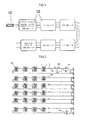
- FIG. 1 is a block diagram illustrating a LED module in accordance with the present invention
- FIG. 2 is a circuit diagram illustrating the LED module in accordance with the present invention.
- the LED lighting module using an AC power in accordance with the present invention includes a power supply 110, unit modules 120, rectifier circuits 130, and constant-current supply circuit 140.
- the power supply 110 is a construction for receiving an AC power source, which is a driving source for the illuminating device, from the outside.
- the external AC power source has a voltage of 220V, a Korean Standard voltage, and the number of the LED elements (L) of the LED driving part 150 as described below is designated accordingly.
- the unit modules 120 includes each unit module consisting of at least two LED sets (S) connected in series together and each LED set (S) consists of one LED element or plural interconnected LED elements driven by an input power received from the power supply 110.
- each LED set (S) consists of three LED elements (L) connected in series.
- the LED set (S) is connected together with a resistance (R) for generating a desired drop of electric pressure on the plural LED sets (S) to constitute the LED driving part 150.
- the LED driving part 150 is a construction to drive the LED elements (L) with a desired voltage by using the rectified power and is configured as a serial connection of a plurality of the LED elements (L) and a resistance (R) in response to the inputted power source.
- the unit modules 120 includes each unit module 120 consisting of four LED sets (S) having three LED elements (L) and each LED set (S) is electrically connected to a single resistance (R). Six unit modules are connected to each other to constitute the entire LED module.
- the rectifier circuits 130 are separately installed in first and last unit modules 120 to which the power is input. That is, the rectifier circuits 130 are configured as any shape of a bridge rectifier circuit when a multiplicity of unit modules forms a loop. Accordingly, the rectifier circuits 130 serve to rectify AC power, which is input through the power supply, thereby allowing the AC power to serve as a drive power for the LED elements. As shown in FIG. 2 , the rectifier circuits 130 are constructed to install two diodes of the bridge rectifier circuit in the first unit module 120 and install the remaining two diodes in the last unit module 120.
- the constant-current supply circuit 140 is installed between the rectifier circuit 130 of the first unit module 120 and the LED set (S).
- the constant-current supply circuit 140 serves to always supply a constant current of the power source to the LED set (S) when the rectified AC power is applied to the LED set (S).
- the constant-current supply circuit 140 can be constructed by a transistor amplifier circuit as shown in FIG.2 .
- the constant-current supply circuit 140 may be an OP amplifier circuit or a regulator circuit and the like.
- the constant-current supply circuit 140 is a constant-current IC of one chip shape so as to more simplify the circuit construction.
- Each unit module 120 includes three pieces of wire so as to drive a mutual LED driving part 150.
- the three pieces of wire includes one piece of wire for connecting the LED driving part 150, which is formed at each unit module 120, in series through the divided rectifier circuit 130 and two pieces of wire for supplying the AC power to the entire unit modules 120.
- LED sets (S) have three LED elements (L) respectively and generate a drop of electric pressure on series connection of 223V by calculating 3.1 V (LED driving voltage) ⁇ 3 ⁇ 24.
- the driving current of the LED elements (L) is controlled by using 77V obtained by subtracting 223V from 300V, which is a peak value of a power source of 220V power, a Korean Standard voltage.
- each unit module 120 can be constructed to have the entire LED elements of 2-100.
- the constant-current supply circuit 140 and a part of the rectifier circuits 130 are constructed in the first unit module 120, the remaining rectifier circuit 130 is constructed in sixth unit module 120, and only LED driving parts 150 are second to fifth unit modules 120.
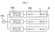
- FIG. 3 is a circuit diagram illustrating a LED module having a plurality of unit block circuits in accordance with the present invention.
- the LED lighting module using an AC power in accordance with the present invention includes a plurality of unit block circuits (B) having at least two unit modules 120 and one rectifier circuit 130.
- the plurality of unit block circuits (B) is electrically connected to each other in parallel.
- Each unit block circuit (B) receives the AC power from a single power supply 110 to constitute a single LED lighting product.
- Each unit block circuit (B) of the LED lighting module forms a closed loop capable of independently driving it through the inputted power. Where each unit block circuit (B) is applied to a sign lamp, an indoor lamp, an outdoor lamp or an interior lamp etc., as though parts of the unit block circuits (B) are out of order, other unit block circuits (B) can be normally operated.
- each unit block circuit (B) is applied to a module shape in LED lighting device, since only broken modules can be repaired or replaced, the maintenance can be easily conducted.
- FIG. 4 is an exploded view illustrating a LED lighting module in accordance with an additional embodiment of the present invention
- FIG. 5 is a side sectional view illustrating a LED lighting module in accordance with an additional embodiment of the present invention.
- the LED lighting module in accordance with the additional embodiment of the present invention presents a structural construction applied to a sign lamp etc. having the unit modules and rectifier circuits according to the first embodiment of the present invention.
- the LED lighting module in accordance with the additional embodiment of the present invention has a basic construction including a mount 1, a LED driving part 2, an angle extension lens 3, and an angle adjusting part 4.
- the angle adjusting part 4 serves to connect the mount 1 to an installing surface 5.
- the installing surface 5 is an upper surface of a base 6.
- the base 6 is coupled to an inner surface of a channel sign, or a wall surface or bottom surface of a structure for implementing an interior through a screw or an adhesive and so on.
- the base 6 can be excluded when the angle adjusting part 4 is directly mounted on the inner surface of a channel sign, or the wall surface or bottom surface of the structure.
- the mount 1 of a plate shape includes LED elements 31 mounted on an upper surface thereof.
- the flickering and luminance of the LED element 31 can be controlled by the LED driving part 2.
- the LED driving part 2 means the unit modules and rectifier circuits according to the first embodiment of the present invention. Also, the LED driving part 2 itself may be the unit block circuit (B) or the plurality of unit block circuits (B) electrically connected to each other in parallel.
- the angle extension lens 3 serves to extend an emitting angle of light of the LED element 31.
- the angle extension lens 3 is coupled to an end portion of the LED element 31.
- the angle extension lens 3 includes an extension groove 3a of "V" shape formed at an inside thereof so as to extend the light emitted from the LED element 31 above horizontal angle to be outputted.
- the emitting angle of light is at least 180 ° -250 ° .
- the extended angle can be obtained by reflecting the light of the LED element 31 on the extension groove 3 a of the angle extension lens 3.
- FIG. 6 is an enlarged sectional view illustrating the angle adjusting part 4 in accordance with an additional embodiment of the present invention.
- the angle adjusting part 4 includes an axis of rotation 50 formed at the mount 1 and a pivot loop 60 mounted on the installing surface 5 of the base 6.
- the axis of rotation 50 is protruded from one side or both sides of the mount 1 so as to adjust the emitted light at various angles. Especially, the axis of rotation 50 is integrally injection-molded with the mount by using the same material. On the other hand, after the axis of rotation 50 is made of a high intensive material, the mount 1 is integrally injection-molded with the axis of rotation 50 so as to increase the intensity of the angle adjusting part 4.
- the pivot loop 60 is mounted on a place of the installing surface 5 corresponding to the axis of rotation 50 of the mount 1.
- the pivot loop 60 has an inner circumference corresponding to an outer circumference of the axis of rotation 50 so as to rotate the inserted axis of rotation 50 therein.
- the pivot loop 60 is open to one side of the inner circumference. That is, the pivot loop 60 has the inner circumference longer than a half length of the outer circumference of the axis of rotation 50 and the remaining section of the inner circumference is made of an elastic body. Therefore, the axis of rotation 50 of the mount 1 can be easily inserted into and mounted on the pivot loop 60 through the opening portion.
- the pivot loop 60 has a rounded end portion extending to the opening portion so as to insert the axis of rotation 50 therein.
- the axis of rotation 50 and the pivot loop 60 includes a latching protrusion 51 and a latching groove 61 respectively.
- the latching protrusion 51 and the latching groove 61 can be selectively formed at any one of the axis of rotation 50 and the pivot loop 60.
- the latching protrusion 51 is formed at the axis of rotation 50 and the latching groove 61 is formed at the pivot loop 60.
- At least one latching protrusion 51 (eight latching protrusion in the drawing) is radially formed at the outer circumference of the axis of rotation 50 and the plurality of the latching groove 61 is formed at the inner circumference of the pivot loop 60.
- the axis of rotation 50 can be rotated at a predetermined angle through the latching reaction thereof, so that the light emitted from the LED element 31 arranged on the mount 1 can be irradiated at various angles.
- the LED driving part 2 including the unit block circuit (B) having the unit modules 120 and rectifier circuits 130 can be formed at a single mount 1 or divisionally formed at the plural mounts 1. At this time, the mount 1 is coupled to the angle adjusting part 4.
- the unit block circuit (B) can be formed at one mount 1 at an one to one rate or the unit block circuit (B) can be formed at two mount 1 at an one to two rate.
- the unit block circuit (B) can be selectively formed according to a shape of LED lighting product and an installation requirement thereof.
Landscapes
- Circuit Arrangement For Electric Light Sources In General (AREA)
- Led Devices (AREA)
- Fastening Of Light Sources Or Lamp Holders (AREA)
Applications Claiming Priority (2)
| Application Number | Priority Date | Filing Date | Title |
|---|---|---|---|
| KR1020080043688A KR101222994B1 (ko) | 2008-05-10 | 2008-05-10 | 교류전원을 이용한 엘이디 조명모듈 |
| PCT/KR2009/002325 WO2009139550A2 (ko) | 2008-05-10 | 2009-05-01 | 교류전원을 이용한 엘이디 조명모듈 |
Publications (1)
| Publication Number | Publication Date |
|---|---|
| EP2296444A2 true EP2296444A2 (de) | 2011-03-16 |
Family
ID=41319143
Family Applications (1)
| Application Number | Title | Priority Date | Filing Date |
|---|---|---|---|
| EP09746729A Withdrawn EP2296444A2 (de) | 2008-05-10 | 2009-05-01 | Wechselstrom verwendendes led-beleuchtungsmodul |
Country Status (5)
| Country | Link |
|---|---|
| US (1) | US8632205B2 (de) |
| EP (1) | EP2296444A2 (de) |
| JP (1) | JP2011520234A (de) |
| KR (1) | KR101222994B1 (de) |
| WO (1) | WO2009139550A2 (de) |
Families Citing this family (4)
| Publication number | Priority date | Publication date | Assignee | Title |
|---|---|---|---|---|
| CN102340904B (zh) | 2010-07-14 | 2015-06-17 | 通用电气公司 | 发光二极管驱动装置及其驱动方法 |
| DE102011003608A1 (de) * | 2010-08-20 | 2012-02-23 | Tridonic Gmbh & Co. Kg | Gehäustes LED-Modul |
| JP5310708B2 (ja) * | 2010-12-22 | 2013-10-09 | 日亜化学工業株式会社 | 発光ユニット及びそれを用いた発光装置 |
| US8674622B2 (en) | 2011-06-20 | 2014-03-18 | Sparton Corporation | LED-based lighting module and control method |
Family Cites Families (9)
| Publication number | Priority date | Publication date | Assignee | Title |
|---|---|---|---|---|
| JPH05299739A (ja) * | 1992-04-24 | 1993-11-12 | Tokyo Electron Ltd | 発光素子の保護回路 |
| US7014336B1 (en) * | 1999-11-18 | 2006-03-21 | Color Kinetics Incorporated | Systems and methods for generating and modulating illumination conditions |
| JPH11162234A (ja) * | 1997-11-25 | 1999-06-18 | Matsushita Electric Works Ltd | 発光ダイオードを用いた光源 |
| US8093823B1 (en) * | 2000-02-11 | 2012-01-10 | Altair Engineering, Inc. | Light sources incorporating light emitting diodes |
| JP3929885B2 (ja) * | 2002-12-06 | 2007-06-13 | シーケーディ株式会社 | Led照明装置、led照明装置の製造装置、及び、led照明装置の製造方法 |
| KR100457878B1 (ko) * | 2003-05-22 | 2004-11-18 | 김용호 | Led 램프용 안정기 회로 |
| KR100555088B1 (ko) * | 2004-03-23 | 2006-02-24 | 서울반도체 주식회사 | 광고 표시장치용 모듈 |
| JP4969789B2 (ja) * | 2005-02-28 | 2012-07-04 | 小泉産業株式会社 | ショーケースの照明構造 |
| KR100755615B1 (ko) * | 2006-04-14 | 2007-09-06 | 삼성전기주식회사 | 발광 다이오드를 이용한 액정 표시 장치의 백라이트 |
-
2008
- 2008-05-10 KR KR1020080043688A patent/KR101222994B1/ko not_active Expired - Fee Related
-
2009
- 2009-05-01 US US12/988,736 patent/US8632205B2/en not_active Expired - Fee Related
- 2009-05-01 EP EP09746729A patent/EP2296444A2/de not_active Withdrawn
- 2009-05-01 JP JP2011508419A patent/JP2011520234A/ja active Pending
- 2009-05-01 WO PCT/KR2009/002325 patent/WO2009139550A2/ko not_active Ceased
Non-Patent Citations (1)
| Title |
|---|
| See references of WO2009139550A2 * |
Also Published As
| Publication number | Publication date |
|---|---|
| US20110043135A1 (en) | 2011-02-24 |
| KR20090117855A (ko) | 2009-11-13 |
| US8632205B2 (en) | 2014-01-21 |
| JP2011520234A (ja) | 2011-07-14 |
| KR101222994B1 (ko) | 2013-01-17 |
| WO2009139550A3 (ko) | 2010-02-25 |
| WO2009139550A2 (ko) | 2009-11-19 |
Similar Documents
| Publication | Publication Date | Title |
|---|---|---|
| US8890414B2 (en) | Lighting module | |
| JP6150977B2 (ja) | 照明用光源及び照明装置 | |
| US7824070B2 (en) | LED lighting fixture | |
| US9078310B2 (en) | Configurable LED driver/dimmer for solid state lighting applications | |
| CN105423169B (zh) | 固态照明装置 | |
| US20110006688A1 (en) | Led lamp device | |
| EP2293653A2 (de) | Mit wechselstrom betriebenes led-beleuchtungssystem | |
| CN105379421B (zh) | 具有内建可编程性的集成的微发光二极管模块 | |
| CA2835213A1 (en) | Flat panel lighting device and driving circuitry | |
| HK1054485B (zh) | 彩色发光二极管的高效驱动器 | |
| JP2006502551A (ja) | Ledベースのモジュール式ランプ | |
| KR20090092215A (ko) | 교류전원에 의해 구동하는 엘이디 조명장치 및 구동회로의 배열방법 | |
| US8632205B2 (en) | LED lighting module using AC power | |
| KR101040145B1 (ko) | 소켓결합구성을 갖는 교류전원 엘이디 조명장치 | |
| KR20140075240A (ko) | 조명 모듈 및 그를 이용한 조명 장치 | |
| CN201992367U (zh) | 超大功率led照明灯 | |
| KR100981753B1 (ko) | 직하광원 방식의 면광원이 적용된 조명기구 | |
| KR101423610B1 (ko) | 형광등기구의 엘이디 램프 | |
| CN214468124U (zh) | 一种可智能变换发光角度的led灯具 | |
| KR20090127208A (ko) | 교류전원에 의해 구동되는 알지비 컬러 엘이디 모듈 | |
| KR20120006969U (ko) | 컨트롤러 일체형 에스엠피에스 | |
| KR20090124843A (ko) | 교류전원에 의해 구동하는 원칩형 엘이디를 적용한 광고용모듈 | |
| KR20110101697A (ko) | 정전류 공급기능을 갖는 교류전원 엘이디 조명장치 |
Legal Events
| Date | Code | Title | Description |
|---|---|---|---|
| PUAI | Public reference made under article 153(3) epc to a published international application that has entered the european phase |
Free format text: ORIGINAL CODE: 0009012 |
|
| 17P | Request for examination filed |
Effective date: 20101208 |
|
| AK | Designated contracting states |
Kind code of ref document: A2 Designated state(s): AT BE BG CH CY CZ DE DK EE ES FI FR GB GR HR HU IE IS IT LI LT LU LV MC MK MT NL NO PL PT RO SE SI SK TR |
|
| AX | Request for extension of the european patent |
Extension state: AL BA RS |
|
| DAX | Request for extension of the european patent (deleted) | ||
| RAP1 | Party data changed (applicant data changed or rights of an application transferred) |
Owner name: STCUBE, INC. |
|
| RIN1 | Information on inventor provided before grant (corrected) |
Inventor name: STCUBE, INC. |
|
| STAA | Information on the status of an ep patent application or granted ep patent |
Free format text: STATUS: THE APPLICATION IS DEEMED TO BE WITHDRAWN |
|
| 18D | Application deemed to be withdrawn |
Effective date: 20161201 |