EP2295182B1 - Lötverfahren für Wärmetauscher - Google Patents
Lötverfahren für Wärmetauscher Download PDFInfo
- Publication number
- EP2295182B1 EP2295182B1 EP10175999.1A EP10175999A EP2295182B1 EP 2295182 B1 EP2295182 B1 EP 2295182B1 EP 10175999 A EP10175999 A EP 10175999A EP 2295182 B1 EP2295182 B1 EP 2295182B1
- Authority
- EP
- European Patent Office
- Prior art keywords
- soldering
- nir
- component
- heat exchangers
- radiation source
- Prior art date
- Legal status (The legal status is an assumption and is not a legal conclusion. Google has not performed a legal analysis and makes no representation as to the accuracy of the status listed.)
- Active
Links
Images


Classifications
-
- B—PERFORMING OPERATIONS; TRANSPORTING
- B23—MACHINE TOOLS; METAL-WORKING NOT OTHERWISE PROVIDED FOR
- B23K—SOLDERING OR UNSOLDERING; WELDING; CLADDING OR PLATING BY SOLDERING OR WELDING; CUTTING BY APPLYING HEAT LOCALLY, e.g. FLAME CUTTING; WORKING BY LASER BEAM
- B23K1/00—Soldering, e.g. brazing, or unsoldering
- B23K1/0008—Soldering, e.g. brazing, or unsoldering specially adapted for particular articles or work
- B23K1/0012—Brazing of heat exchangers
-
- B—PERFORMING OPERATIONS; TRANSPORTING
- B23—MACHINE TOOLS; METAL-WORKING NOT OTHERWISE PROVIDED FOR
- B23K—SOLDERING OR UNSOLDERING; WELDING; CLADDING OR PLATING BY SOLDERING OR WELDING; CUTTING BY APPLYING HEAT LOCALLY, e.g. FLAME CUTTING; WORKING BY LASER BEAM
- B23K1/00—Soldering, e.g. brazing, or unsoldering
- B23K1/005—Soldering by means of radiant energy
- B23K1/0053—Soldering by means of radiant energy soldering by means of infrared [IR]
-
- B—PERFORMING OPERATIONS; TRANSPORTING
- B23—MACHINE TOOLS; METAL-WORKING NOT OTHERWISE PROVIDED FOR
- B23K—SOLDERING OR UNSOLDERING; WELDING; CLADDING OR PLATING BY SOLDERING OR WELDING; CUTTING BY APPLYING HEAT LOCALLY, e.g. FLAME CUTTING; WORKING BY LASER BEAM
- B23K2101/00—Articles made by soldering, welding or cutting
- B23K2101/04—Tubular or hollow articles
- B23K2101/14—Heat exchangers
Definitions
- the invention relates to a method for soldering heat exchangers, which consist at least partially of aluminum or an aluminum alloy.
- Heat exchangers or absorber modules of a solar collector comprise a plurality of solder joints which are conventionally soldered by vacuum brazing or Controlled Atmosphere Brazing (CAB).
- CAB soldering typically uses a flux. Both in vacuum brazing and CAB brazing, the components are previously preheated either under an air atmosphere or in an inert gas atmosphere. This process takes about 10 to 15 minutes.
- a method for soldering two metal parts is already out of EP 1 302 268 A1 known.
- the solder is liquefied directly or indirectly by the use of an infrared radiation source and can thus connect the two metal parts together after cooling.
- the radiation source acts directly on the solder, in an indirect procedure, the solder is indirectly heated by a metal part, which is exposed to the infrared radiation source.
- the wavelengths used for heating are in a range between 2 and 10 microns.
- the method has shortcomings in the heating of metals with high reflection coefficients, such as copper with a reflection coefficient in the IR spectral range between 80 and 95%. Only by using an absorber coating that absorbs well in the IR range can a copper plate be heated sufficiently effectively.
- the WO 91/04824 discloses a method for soldering components for surface mounting of circuit boards, wherein the boards do not have through-holes by a combination of convection soldering and heating by an infrared radiation source.
- JP 2004358484 which is based on the preamble of claim 1, a method for soldering heat exchangers made of aluminum or copper is known, in which NIR radiation is to be used.
- the present invention has therefore set itself the task of providing an improved soldering process for heat exchangers made of aluminum or an aluminum alloy, with which significantly shorter cycle times can be achieved.
- the object is achieved by a method having the features of claim 1.
- the NIR radiation source has clear advantages over the conventionally used convective heat sources, because the NIR radiation sources heat the components by absorbing the heat radiation in the metal itself. Even components that are not surrounded by an atmosphere as in vacuum brazing can be heated very effectively. In comparison to conventional infrared radiation sources, the heat input of the NIR radiation source is significantly increased, since the emitted photons release significantly more energy in the absorbing medium due to their shorter wavelength. NIR radiation sources have their intensity maximum in the wavelength range of 800 nm to 1500 nm and are often realized by specially wound halogen lamps.
- the soldering method according to the invention is very energy-saving due to the direct heating of the components by the NIR radiation.
- At least one soldering point arranged in the interior of the components is soldered.
- the heating of the components using the NIR radiation source shows, especially due to the good thermal conductivity of aluminum very good soldering results also in the production of solder joints, which are located inside the components.
- the heating by the NIR radiation sources is so effective that within a few seconds, the existing Aluminiumlot Anlagen, the solder foil or solder paste used is brought to a temperature above the solidus temperature of the corresponding aluminum alloy, the solder melts and a solder joint is produced.
- the ovens or evacuatable solder gauges used for this purpose can be well used for the dimensions of the components to be soldered and, above all, with minimal volume.
- a soldering furnace with a reduced volume requires significantly less inert gas in the CAB soldering process and can therefore be operated much more favorably.
- By reducing the volumes of the evacuated Lötlehren results also the advantage that the evacuation is cheaper and the entire handling of the soldering jig is much easier. Both lead to a reduction in costs.
- NIR radiation source aluminum or an aluminum alloy has a very good heat conduction, heating on both sides results in very short heating phases up to the soldering temperature. It is possible in this embodiment of the method according to the invention to heat a component using a single NIR radiation source on several sides.
- NIR radiation source for example, reflectors or optical fibers can be used to guide the NIR radiation to the component.
- two NIR radiation sources can also be used to heat the component from two sides.
- the energy requirement of the soldering process can be reduced by switching on the NIR radiation source only for heating the component to be soldered. Since the energy transfer takes place on the component to be soldered by the NIR radiation, no heating phase of the furnace is required. If no component is present in the furnace, therefore, the NIR radiation source can be turned off and thus energy saved.
- the heating rate of the components and thus the cycle time with which components can be soldered using the method according to the invention can be accelerated according to the invention be that the components at least partially have a high temperature resistant coating, which selectively absorbs in the NIR wavelength range of 800 nm to 1500 nm. As a result of this coating, the proportion of electromagnetic radiation reflected by the component in the NIR wave range is greatly reduced, so that substantially more NIR radiation is absorbed and thus more energy is absorbed by the component.
- the waste heat of at least one NIR radiation source is used for an additional convective heating of the component to be soldered.
- the preheating also leads to a reduction in the voltages in the component.
- the heating phase is further reduced in time, since the component is not heated from room temperature using the NIR radiation sources to very high temperatures, for example of 600 ° C.
- solder gauges for performing a vacuum soldering are also advantageous when using the NIR radiation sources, because the solder gauges can be made particularly small and require transparent walls for the passage of the radiation energy only in this wavelength range.
- the temperature of the components in the heating area is measured using at least one pyrometer, It is possible to perform the soldering process in a particularly controlled manner, since the NIR radiation sources act directly on the temperature of the component by regulating their power output. This makes it possible to adhere to and apply particularly exact soldering profiles.
- the heating of the component takes place at soldering temperature in less than 10 seconds, preferably in 5 seconds or less. This allows particularly high cycle rates, since, for example, the soldering process can be completed within a few minutes, or in less than a minute. The process time is thus reduced by a factor of 5 to 15.
- the component may at least partially have a selectively absorbing in the NIR wavelength range of 800 nm to 1500 nm coating, which soldering temperatures from about 600 ° C without damage survives. These components make it possible, in conjunction with the method according to the invention, to achieve significantly shorter cycle times As the heating of the components to soldering temperature of about 600 ° C is completed within a few seconds.
- the component is a heat exchanger, since these have a particularly high number of solder joints, which lie in the interior of the components, which can be soldered particularly effectively with the method according to the invention.
- the device 1 for carrying out the method according to the invention consists of a NIR oven 2 with NIR radiation sources 3 and 3 'and means 4, which are used for transporting the component 5 to be soldered.
- the radiation sources 3 and 3 ' are from both sides, i. at the top and bottom of the component 5, so that the component 5 is heated on both sides as it passes through the NIR furnace.
- means 6 and 6 ' which utilize the waste heat from the radiation sources 3 and 3' in order to convectively preheat the component 5 before entering the NIR furnace 2, are shown schematically.
- the component 5 can also be arranged, for example, in a soldering jig, which is not shown, and vacuum-soldered with the NIR furnace, for example. It is important that the windows of the soldering gauge are transparent to radiation from the wavelength range of 800 nm to 1500 nm.
- the component With the preheating by the means 6, 6 ', the component is already heated to a temperature well above room temperature. The stresses that are introduced due to the rapid increase in temperature in the NIR furnace 2 can thus be reduced. After emerging from the NIR oven 2, the component 5 cools, so that the solder joints cool and solidify. The speed with which the component 5 passes through the NIR furnace 2, can be relatively large, since even at a heating phase of less than 10 seconds, the component can be brought to the soldering temperature of about 600 ° C.
- Pyrometer 7 can detect the temperature of the component 5 without contact and thus control or regulate the radiation sources and their energy input into the component 5. This makes the soldering process particularly easy to control.
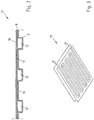
- Fig. 2 shows a sectional view of a solar collector 13, which does not belong to the invention, which consists of two aluminum sheets 8 and 9, wherein the aluminum sheet 8 additionally comprises a coating 10 which selectively in the wavelength range of 800 nm to 1500 nm, ie in the NIR wavelength range, absorbed electromagnetic radiation.
- the heating phase can thereby be reduced even further, since the component 13 can absorb more energy in the NIR furnace 2 through the increased absorption of the NIR radiation.
- the solder joints 11 which are arranged inside and are therefore not accessible to immediate heating from the outside.
- the heat media leading channels 12 which are arranged between the solder joints 11.
- Fig. 3 shows an example of a solar collector 13, which does not belong to the invention, in a perspective view. It can be clearly seen that the absorber module 13 of a solar collector has large-area solder joints. By using NIR radiation sources, the component can be heated over a large area and evenly brought to soldering temperature. The cycle times for the soldering of the solar collector 13 are particularly short due to the provided, selectively absorbing in the NIR wavelength range coating. The coating must Of course, be high temperature resistant so that it withstands the soldering temperatures of about 600 ° C without damage.
- a heat exchanger as seen in a side view Fig. 4 is shown, has a plurality of solder joints 15 and consists of a plurality of sheets and foils.
- the outer sheets 16, 17 are coated with a selectively absorbing in the NIR wavelength range coating 18 and 19, so that can be particularly effectively heated by an NIR radiation source on both sides of the heat exchanger.
- Fig. 5 a typical soldering profile in a time-temperature diagram.
- RT is the room temperature and LT is the soldering temperature.
- the soldering temperature is usually about 600 ° C and thus above the solidus temperature of the commonly used aluminum-silicon-aluminum solders.
- On the ordinate of the diagram is the temperature of the metal component and on the abscissa the time is plotted.
- the component initially has room temperature RT and is preheated by means 6 or 6 'until time t 1 .
- time t 1 the component 5 enters the NIR oven 2 and is heated to soldering temperature of about 600 ° C. within a few seconds until time t 2 .
- the component is held at soldering temperature for a certain time, for example for 30 seconds. Subsequently, the component cools after leaving the NIR oven 2 from the time t 3 on. From the time t 4 , the component temperature is already significantly lower than the solidus temperature of the aluminum solder, so that the solder joints cool and solidify.
Landscapes
- Engineering & Computer Science (AREA)
- Mechanical Engineering (AREA)
- Electric Connection Of Electric Components To Printed Circuits (AREA)
- Coating With Molten Metal (AREA)
Priority Applications (1)
| Application Number | Priority Date | Filing Date | Title |
|---|---|---|---|
| PL10175999T PL2295182T3 (pl) | 2009-09-11 | 2010-09-09 | Sposób lutowania wymienników ciepła |
Applications Claiming Priority (1)
| Application Number | Priority Date | Filing Date | Title |
|---|---|---|---|
| DE102009043985A DE102009043985A1 (de) | 2009-09-11 | 2009-09-11 | Lötverfahren für Wärmetauscher und Solarkollektoren |
Publications (3)
| Publication Number | Publication Date |
|---|---|
| EP2295182A2 EP2295182A2 (de) | 2011-03-16 |
| EP2295182A3 EP2295182A3 (de) | 2012-03-21 |
| EP2295182B1 true EP2295182B1 (de) | 2017-12-06 |
Family
ID=43413486
Family Applications (1)
| Application Number | Title | Priority Date | Filing Date |
|---|---|---|---|
| EP10175999.1A Active EP2295182B1 (de) | 2009-09-11 | 2010-09-09 | Lötverfahren für Wärmetauscher |
Country Status (3)
| Country | Link |
|---|---|
| EP (1) | EP2295182B1 (pl) |
| DE (1) | DE102009043985A1 (pl) |
| PL (1) | PL2295182T3 (pl) |
Families Citing this family (2)
| Publication number | Priority date | Publication date | Assignee | Title |
|---|---|---|---|---|
| FR2983423B1 (fr) * | 2011-12-01 | 2014-08-29 | Valeo Systemes Thermiques | Piece metallique a braser, en particulier pour systeme de gestion thermique, et son procede de preparation |
| CN103157875B (zh) * | 2013-03-20 | 2015-05-06 | 上海交通大学 | 一种使用金属石英一体化辐射加热器的真空钎焊炉 |
Citations (1)
| Publication number | Priority date | Publication date | Assignee | Title |
|---|---|---|---|---|
| JP2004358484A (ja) * | 2003-06-02 | 2004-12-24 | Matsushita Electric Ind Co Ltd | ろう付け装置 |
Family Cites Families (7)
| Publication number | Priority date | Publication date | Assignee | Title |
|---|---|---|---|---|
| WO1991004824A1 (en) * | 1989-09-28 | 1991-04-18 | Electrovert Ltd. | Combined i.r./convection reflow soldering system |
| DE19716757A1 (de) * | 1997-04-12 | 1998-10-15 | Niemeier Joerg Dipl Ing Dipl I | Vorrichtung zur berührungslosen örtlich begrenzten Erwärmung von Material mit Hilfe von gebündelter Strahlung |
| DE10022840A1 (de) * | 2000-05-10 | 2001-11-15 | Solvay Fluor & Derivate | Laserstrahllöten von Aluminiumlegierungen |
| US20020139781A1 (en) * | 2001-02-01 | 2002-10-03 | Milewski John O. | Method and apparatus for brazing and thermal processing |
| DE10146652A1 (de) * | 2001-09-21 | 2003-04-10 | Ikarus Solar Ag | Verfahren zum Verbinden von Metallteilen |
| DE10343463A1 (de) * | 2003-09-19 | 2005-04-14 | Emitec Gesellschaft Für Emissionstechnologie Mbh | Verfahren zur Herstellung von aluminiumhaltigen Wabenkörpern mit Strahlungsheizern |
| JP2005103019A (ja) * | 2003-09-30 | 2005-04-21 | Shyi-Kaan Wu | 赤外線快速接合製造工程を使用したゴルフクラブヘッドの製造方法 |
-
2009
- 2009-09-11 DE DE102009043985A patent/DE102009043985A1/de not_active Withdrawn
-
2010
- 2010-09-09 PL PL10175999T patent/PL2295182T3/pl unknown
- 2010-09-09 EP EP10175999.1A patent/EP2295182B1/de active Active
Patent Citations (1)
| Publication number | Priority date | Publication date | Assignee | Title |
|---|---|---|---|---|
| JP2004358484A (ja) * | 2003-06-02 | 2004-12-24 | Matsushita Electric Ind Co Ltd | ろう付け装置 |
Non-Patent Citations (1)
| Title |
|---|
| "A Handbook of Chemical Analysis", 31 December 2005, INTERNATIONAL SCIENTIFIC PUBLISHING ACADEMY, India, ISBN: 978-8-18-293008-7, article POOJA BHAGWAN: "A Handbook of Chemical Analysis", pages: 87, XP055062808 * |
Also Published As
| Publication number | Publication date |
|---|---|
| PL2295182T3 (pl) | 2018-03-30 |
| EP2295182A2 (de) | 2011-03-16 |
| EP2295182A3 (de) | 2012-03-21 |
| DE102009043985A1 (de) | 2011-03-24 |
Similar Documents
| Publication | Publication Date | Title |
|---|---|---|
| DE102017206476B4 (de) | Externes wärmeunterstütztes schweissen von ungleichen metallwerkstücken | |
| EP2200797B1 (de) | Verfahren zum herstellen eines faserverbundbauteils | |
| DE112009001365B4 (de) | Glasverschmelzungsverfahren | |
| DE69212774T2 (de) | Hitzbeständige Platte mit Kühlstruktur und Herstellungsverfahren | |
| EP2701190A2 (de) | Kühlkörper für mindestens ein zu kühlendes Bauelement sowie Verfahren zur Herstellung eines Kühlkörpers | |
| DE112009001326T5 (de) | Schmelzverbindungsprozess für Glas | |
| DE19938807A1 (de) | Verfahren zur Formgebung von Glasteilen | |
| DE2757457C3 (de) | Verfahren zum flußmittellosen Hartlöten von Aluminiumbauteilen | |
| DE4201275C1 (pl) | ||
| EP2295182B1 (de) | Lötverfahren für Wärmetauscher | |
| DE102018001460A1 (de) | Verfahren und Vorrichtung zum stoffschlüssigen Verbinden metallischer Werkstoffe mittels zumindest einer Laserstrahlquelle | |
| EP1834137A1 (de) | Absorber f]r einen thermischen solarkollektor und verfahren zum herstellen eines derartigen absorbers | |
| EP1433559B1 (de) | Verfahren zum Fügen von Werkstücken aus Titanaluminid mittels eines Laser-Lötverfahrens | |
| EP1200976B1 (de) | Herstellungsverfahren für eine gasentladungslampe | |
| DE102006010220A1 (de) | Herstellungsverfahren, Lötvorrichtung und Metallgegenstand | |
| DE10306930B3 (de) | Absorber für einen thermischen Kollektor einer Solaranlage sowie Verfahren zu dessen Herstellung | |
| WO2005081371A2 (de) | Verfahren zum herstellen von plattenstapeln, insbesondere von aus plattenstapeln bestehenden kühlern oder kühlerelementen | |
| DE102009043986B3 (de) | Verfahren zur Herstellung von Solarkollektoren | |
| DE3303568C2 (de) | Verfahren zum hitzebeständigen Verbinden von Graphitplatten untereinander oder mit metallischen Untergründen | |
| DE102013016316B4 (de) | Verfahren zur Herstellung eines Absorbers für einen Solarkollektor einer Solarthermieanlage | |
| EP3934830B1 (de) | Pulver zum lasersintern und verwendung | |
| EP1055465A2 (de) | Verfahren und Vorrichtung zum Tiefziehen von Blechformteilen | |
| EP1677938B1 (de) | Verfahren zur herstellung von aluminiumhaltigen wabenkörpern mit strahlungsheizern | |
| DE102021202737A1 (de) | Verfahren zum Verbinden eines wärmeerzeugenden Bauteils mit einer Kühlvorrichtung | |
| AT411023B (de) | Laserunterstütztes tiefziehen mit halbleiterlasern und festkörperlasern |
Legal Events
| Date | Code | Title | Description |
|---|---|---|---|
| PUAI | Public reference made under article 153(3) epc to a published international application that has entered the european phase |
Free format text: ORIGINAL CODE: 0009012 |
|
| AK | Designated contracting states |
Kind code of ref document: A2 Designated state(s): AL AT BE BG CH CY CZ DE DK EE ES FI FR GB GR HR HU IE IS IT LI LT LU LV MC MK MT NL NO PL PT RO SE SI SK SM TR |
|
| AX | Request for extension of the european patent |
Extension state: BA ME RS |
|
| PUAL | Search report despatched |
Free format text: ORIGINAL CODE: 0009013 |
|
| AK | Designated contracting states |
Kind code of ref document: A3 Designated state(s): AL AT BE BG CH CY CZ DE DK EE ES FI FR GB GR HR HU IE IS IT LI LT LU LV MC MK MT NL NO PL PT RO SE SI SK SM TR |
|
| AX | Request for extension of the european patent |
Extension state: BA ME RS |
|
| RIC1 | Information provided on ipc code assigned before grant |
Ipc: B23P 15/26 20060101ALI20120210BHEP Ipc: B23K 1/00 20060101AFI20120210BHEP Ipc: B23K 1/005 20060101ALI20120210BHEP |
|
| 17P | Request for examination filed |
Effective date: 20120920 |
|
| RAP1 | Party data changed (applicant data changed or rights of an application transferred) |
Owner name: HYDRO ALUMINIUM DEUTSCHLAND GMBH |
|
| 17Q | First examination report despatched |
Effective date: 20130528 |
|
| GRAP | Despatch of communication of intention to grant a patent |
Free format text: ORIGINAL CODE: EPIDOSNIGR1 |
|
| RIC1 | Information provided on ipc code assigned before grant |
Ipc: B23K 1/005 20060101ALI20170306BHEP Ipc: B23K 101/14 20060101ALI20170306BHEP Ipc: B23K 1/00 20060101AFI20170306BHEP Ipc: B23P 15/26 20060101ALI20170306BHEP |
|
| INTG | Intention to grant announced |
Effective date: 20170412 |
|
| GRAS | Grant fee paid |
Free format text: ORIGINAL CODE: EPIDOSNIGR3 |
|
| RAP1 | Party data changed (applicant data changed or rights of an application transferred) |
Owner name: HYDRO ALUMINIUM ROLLED PRODUCTS GMBH |
|
| GRAA | (expected) grant |
Free format text: ORIGINAL CODE: 0009210 |
|
| AK | Designated contracting states |
Kind code of ref document: B1 Designated state(s): AL AT BE BG CH CY CZ DE DK EE ES FI FR GB GR HR HU IE IS IT LI LT LU LV MC MK MT NL NO PL PT RO SE SI SK SM TR |
|
| REG | Reference to a national code |
Ref country code: GB Ref legal event code: FG4D Free format text: NOT ENGLISH |
|
| REG | Reference to a national code |
Ref country code: AT Ref legal event code: REF Ref document number: 951948 Country of ref document: AT Kind code of ref document: T Effective date: 20171215 Ref country code: CH Ref legal event code: EP |
|
| REG | Reference to a national code |
Ref country code: IE Ref legal event code: FG4D Free format text: LANGUAGE OF EP DOCUMENT: GERMAN |
|
| REG | Reference to a national code |
Ref country code: CH Ref legal event code: NV Representative=s name: SCHMAUDER AND PARTNER AG PATENT- UND MARKENANW, CH |
|
| REG | Reference to a national code |
Ref country code: DE Ref legal event code: R096 Ref document number: 502010014445 Country of ref document: DE |
|
| REG | Reference to a national code |
Ref country code: SE Ref legal event code: TRGR |
|
| REG | Reference to a national code |
Ref country code: NL Ref legal event code: MP Effective date: 20171206 |
|
| REG | Reference to a national code |
Ref country code: LT Ref legal event code: MG4D |
|
| PG25 | Lapsed in a contracting state [announced via postgrant information from national office to epo] |
Ref country code: LT Free format text: LAPSE BECAUSE OF FAILURE TO SUBMIT A TRANSLATION OF THE DESCRIPTION OR TO PAY THE FEE WITHIN THE PRESCRIBED TIME-LIMIT Effective date: 20171206 Ref country code: NO Free format text: LAPSE BECAUSE OF FAILURE TO SUBMIT A TRANSLATION OF THE DESCRIPTION OR TO PAY THE FEE WITHIN THE PRESCRIBED TIME-LIMIT Effective date: 20180306 Ref country code: FI Free format text: LAPSE BECAUSE OF FAILURE TO SUBMIT A TRANSLATION OF THE DESCRIPTION OR TO PAY THE FEE WITHIN THE PRESCRIBED TIME-LIMIT Effective date: 20171206 Ref country code: ES Free format text: LAPSE BECAUSE OF FAILURE TO SUBMIT A TRANSLATION OF THE DESCRIPTION OR TO PAY THE FEE WITHIN THE PRESCRIBED TIME-LIMIT Effective date: 20171206 |
|
| PG25 | Lapsed in a contracting state [announced via postgrant information from national office to epo] |
Ref country code: LV Free format text: LAPSE BECAUSE OF FAILURE TO SUBMIT A TRANSLATION OF THE DESCRIPTION OR TO PAY THE FEE WITHIN THE PRESCRIBED TIME-LIMIT Effective date: 20171206 Ref country code: GR Free format text: LAPSE BECAUSE OF FAILURE TO SUBMIT A TRANSLATION OF THE DESCRIPTION OR TO PAY THE FEE WITHIN THE PRESCRIBED TIME-LIMIT Effective date: 20180307 Ref country code: HR Free format text: LAPSE BECAUSE OF FAILURE TO SUBMIT A TRANSLATION OF THE DESCRIPTION OR TO PAY THE FEE WITHIN THE PRESCRIBED TIME-LIMIT Effective date: 20171206 Ref country code: BG Free format text: LAPSE BECAUSE OF FAILURE TO SUBMIT A TRANSLATION OF THE DESCRIPTION OR TO PAY THE FEE WITHIN THE PRESCRIBED TIME-LIMIT Effective date: 20180306 |
|
| PG25 | Lapsed in a contracting state [announced via postgrant information from national office to epo] |
Ref country code: NL Free format text: LAPSE BECAUSE OF FAILURE TO SUBMIT A TRANSLATION OF THE DESCRIPTION OR TO PAY THE FEE WITHIN THE PRESCRIBED TIME-LIMIT Effective date: 20171206 |
|
| PG25 | Lapsed in a contracting state [announced via postgrant information from national office to epo] |
Ref country code: EE Free format text: LAPSE BECAUSE OF FAILURE TO SUBMIT A TRANSLATION OF THE DESCRIPTION OR TO PAY THE FEE WITHIN THE PRESCRIBED TIME-LIMIT Effective date: 20171206 Ref country code: SK Free format text: LAPSE BECAUSE OF FAILURE TO SUBMIT A TRANSLATION OF THE DESCRIPTION OR TO PAY THE FEE WITHIN THE PRESCRIBED TIME-LIMIT Effective date: 20171206 |
|
| PG25 | Lapsed in a contracting state [announced via postgrant information from national office to epo] |
Ref country code: IT Free format text: LAPSE BECAUSE OF FAILURE TO SUBMIT A TRANSLATION OF THE DESCRIPTION OR TO PAY THE FEE WITHIN THE PRESCRIBED TIME-LIMIT Effective date: 20171206 Ref country code: SM Free format text: LAPSE BECAUSE OF FAILURE TO SUBMIT A TRANSLATION OF THE DESCRIPTION OR TO PAY THE FEE WITHIN THE PRESCRIBED TIME-LIMIT Effective date: 20171206 Ref country code: RO Free format text: LAPSE BECAUSE OF FAILURE TO SUBMIT A TRANSLATION OF THE DESCRIPTION OR TO PAY THE FEE WITHIN THE PRESCRIBED TIME-LIMIT Effective date: 20171206 |
|
| REG | Reference to a national code |
Ref country code: DE Ref legal event code: R097 Ref document number: 502010014445 Country of ref document: DE |
|
| REG | Reference to a national code |
Ref country code: FR Ref legal event code: PLFP Year of fee payment: 9 |
|
| PG25 | Lapsed in a contracting state [announced via postgrant information from national office to epo] |
Ref country code: MT Free format text: LAPSE BECAUSE OF FAILURE TO SUBMIT A TRANSLATION OF THE DESCRIPTION OR TO PAY THE FEE WITHIN THE PRESCRIBED TIME-LIMIT Effective date: 20171206 |
|
| PLBE | No opposition filed within time limit |
Free format text: ORIGINAL CODE: 0009261 |
|
| STAA | Information on the status of an ep patent application or granted ep patent |
Free format text: STATUS: NO OPPOSITION FILED WITHIN TIME LIMIT |
|
| 26N | No opposition filed |
Effective date: 20180907 |
|
| PG25 | Lapsed in a contracting state [announced via postgrant information from national office to epo] |
Ref country code: DK Free format text: LAPSE BECAUSE OF FAILURE TO SUBMIT A TRANSLATION OF THE DESCRIPTION OR TO PAY THE FEE WITHIN THE PRESCRIBED TIME-LIMIT Effective date: 20171206 Ref country code: SI Free format text: LAPSE BECAUSE OF FAILURE TO SUBMIT A TRANSLATION OF THE DESCRIPTION OR TO PAY THE FEE WITHIN THE PRESCRIBED TIME-LIMIT Effective date: 20171206 |
|
| PG25 | Lapsed in a contracting state [announced via postgrant information from national office to epo] |
Ref country code: MC Free format text: LAPSE BECAUSE OF FAILURE TO SUBMIT A TRANSLATION OF THE DESCRIPTION OR TO PAY THE FEE WITHIN THE PRESCRIBED TIME-LIMIT Effective date: 20171206 |
|
| GBPC | Gb: european patent ceased through non-payment of renewal fee |
Effective date: 20180909 |
|
| REG | Reference to a national code |
Ref country code: BE Ref legal event code: MM Effective date: 20180930 |
|
| REG | Reference to a national code |
Ref country code: IE Ref legal event code: MM4A |
|
| PG25 | Lapsed in a contracting state [announced via postgrant information from national office to epo] |
Ref country code: LU Free format text: LAPSE BECAUSE OF NON-PAYMENT OF DUE FEES Effective date: 20180909 |
|
| PG25 | Lapsed in a contracting state [announced via postgrant information from national office to epo] |
Ref country code: IE Free format text: LAPSE BECAUSE OF NON-PAYMENT OF DUE FEES Effective date: 20180909 |
|
| PG25 | Lapsed in a contracting state [announced via postgrant information from national office to epo] |
Ref country code: BE Free format text: LAPSE BECAUSE OF NON-PAYMENT OF DUE FEES Effective date: 20180930 |
|
| PG25 | Lapsed in a contracting state [announced via postgrant information from national office to epo] |
Ref country code: GB Free format text: LAPSE BECAUSE OF NON-PAYMENT OF DUE FEES Effective date: 20180909 |
|
| PG25 | Lapsed in a contracting state [announced via postgrant information from national office to epo] |
Ref country code: TR Free format text: LAPSE BECAUSE OF FAILURE TO SUBMIT A TRANSLATION OF THE DESCRIPTION OR TO PAY THE FEE WITHIN THE PRESCRIBED TIME-LIMIT Effective date: 20171206 |
|
| PG25 | Lapsed in a contracting state [announced via postgrant information from national office to epo] |
Ref country code: PT Free format text: LAPSE BECAUSE OF FAILURE TO SUBMIT A TRANSLATION OF THE DESCRIPTION OR TO PAY THE FEE WITHIN THE PRESCRIBED TIME-LIMIT Effective date: 20171206 Ref country code: HU Free format text: LAPSE BECAUSE OF FAILURE TO SUBMIT A TRANSLATION OF THE DESCRIPTION OR TO PAY THE FEE WITHIN THE PRESCRIBED TIME-LIMIT; INVALID AB INITIO Effective date: 20100909 |
|
| PG25 | Lapsed in a contracting state [announced via postgrant information from national office to epo] |
Ref country code: MK Free format text: LAPSE BECAUSE OF NON-PAYMENT OF DUE FEES Effective date: 20171206 Ref country code: CY Free format text: LAPSE BECAUSE OF FAILURE TO SUBMIT A TRANSLATION OF THE DESCRIPTION OR TO PAY THE FEE WITHIN THE PRESCRIBED TIME-LIMIT Effective date: 20171206 |
|
| PG25 | Lapsed in a contracting state [announced via postgrant information from national office to epo] |
Ref country code: AL Free format text: LAPSE BECAUSE OF FAILURE TO SUBMIT A TRANSLATION OF THE DESCRIPTION OR TO PAY THE FEE WITHIN THE PRESCRIBED TIME-LIMIT Effective date: 20171206 Ref country code: IS Free format text: LAPSE BECAUSE OF FAILURE TO SUBMIT A TRANSLATION OF THE DESCRIPTION OR TO PAY THE FEE WITHIN THE PRESCRIBED TIME-LIMIT Effective date: 20180406 |
|
| REG | Reference to a national code |
Ref country code: DE Ref legal event code: R081 Ref document number: 502010014445 Country of ref document: DE Owner name: SPEIRA GMBH, DE Free format text: FORMER OWNER: HYDRO ALUMINIUM ROLLED PRODUCTS GMBH, 41515 GREVENBROICH, DE |
|
| REG | Reference to a national code |
Ref country code: AT Ref legal event code: HC Ref document number: 951948 Country of ref document: AT Kind code of ref document: T Owner name: SPEIRA GMBH, DE Effective date: 20220711 |
|
| P01 | Opt-out of the competence of the unified patent court (upc) registered |
Effective date: 20230519 |
|
| REG | Reference to a national code |
Ref country code: CH Ref legal event code: U11 Free format text: ST27 STATUS EVENT CODE: U-0-0-U10-U11 (AS PROVIDED BY THE NATIONAL OFFICE) Effective date: 20251001 |
|
| PGFP | Annual fee paid to national office [announced via postgrant information from national office to epo] |
Ref country code: DE Payment date: 20250922 Year of fee payment: 16 |
|
| PGFP | Annual fee paid to national office [announced via postgrant information from national office to epo] |
Ref country code: PL Payment date: 20250821 Year of fee payment: 16 |
|
| PGFP | Annual fee paid to national office [announced via postgrant information from national office to epo] |
Ref country code: FR Payment date: 20250923 Year of fee payment: 16 Ref country code: AT Payment date: 20250524 Year of fee payment: 16 |
|
| PGFP | Annual fee paid to national office [announced via postgrant information from national office to epo] |
Ref country code: SE Payment date: 20250923 Year of fee payment: 16 |
|
| PGFP | Annual fee paid to national office [announced via postgrant information from national office to epo] |
Ref country code: CZ Payment date: 20250820 Year of fee payment: 16 |
|
| PGFP | Annual fee paid to national office [announced via postgrant information from national office to epo] |
Ref country code: CH Payment date: 20251001 Year of fee payment: 16 |