EP2295098A1 - Medizinische Infusionspumpe und Verfahren zur Bestimmung der Ursache einer Stromunterbrechung in der Pumpe - Google Patents
Medizinische Infusionspumpe und Verfahren zur Bestimmung der Ursache einer Stromunterbrechung in der Pumpe Download PDFInfo
- Publication number
- EP2295098A1 EP2295098A1 EP20090169936 EP09169936A EP2295098A1 EP 2295098 A1 EP2295098 A1 EP 2295098A1 EP 20090169936 EP20090169936 EP 20090169936 EP 09169936 A EP09169936 A EP 09169936A EP 2295098 A1 EP2295098 A1 EP 2295098A1
- Authority
- EP
- European Patent Office
- Prior art keywords
- voltage
- processor
- power source
- infusion pump
- medical infusion
- Prior art date
- Legal status (The legal status is an assumption and is not a legal conclusion. Google has not performed a legal analysis and makes no representation as to the accuracy of the status listed.)
- Granted
Links
- 238000001802 infusion Methods 0.000 title claims abstract description 34
- 238000000034 method Methods 0.000 title claims description 12
- 230000015654 memory Effects 0.000 claims description 19
- NOESYZHRGYRDHS-UHFFFAOYSA-N insulin Chemical compound N1C(=O)C(NC(=O)C(CCC(N)=O)NC(=O)C(CCC(O)=O)NC(=O)C(C(C)C)NC(=O)C(NC(=O)CN)C(C)CC)CSSCC(C(NC(CO)C(=O)NC(CC(C)C)C(=O)NC(CC=2C=CC(O)=CC=2)C(=O)NC(CCC(N)=O)C(=O)NC(CC(C)C)C(=O)NC(CCC(O)=O)C(=O)NC(CC(N)=O)C(=O)NC(CC=2C=CC(O)=CC=2)C(=O)NC(CSSCC(NC(=O)C(C(C)C)NC(=O)C(CC(C)C)NC(=O)C(CC=2C=CC(O)=CC=2)NC(=O)C(CC(C)C)NC(=O)C(C)NC(=O)C(CCC(O)=O)NC(=O)C(C(C)C)NC(=O)C(CC(C)C)NC(=O)C(CC=2NC=NC=2)NC(=O)C(CO)NC(=O)CNC2=O)C(=O)NCC(=O)NC(CCC(O)=O)C(=O)NC(CCCNC(N)=N)C(=O)NCC(=O)NC(CC=3C=CC=CC=3)C(=O)NC(CC=3C=CC=CC=3)C(=O)NC(CC=3C=CC(O)=CC=3)C(=O)NC(C(C)O)C(=O)N3C(CCC3)C(=O)NC(CCCCN)C(=O)NC(C)C(O)=O)C(=O)NC(CC(N)=O)C(O)=O)=O)NC(=O)C(C(C)CC)NC(=O)C(CO)NC(=O)C(C(C)O)NC(=O)C1CSSCC2NC(=O)C(CC(C)C)NC(=O)C(NC(=O)C(CCC(N)=O)NC(=O)C(CC(N)=O)NC(=O)C(NC(=O)C(N)CC=1C=CC=CC=1)C(C)C)CC1=CN=CN1 NOESYZHRGYRDHS-UHFFFAOYSA-N 0.000 description 6
- 238000005070 sampling Methods 0.000 description 4
- 102000004877 Insulin Human genes 0.000 description 3
- 108090001061 Insulin Proteins 0.000 description 3
- 239000003990 capacitor Substances 0.000 description 3
- 229940125396 insulin Drugs 0.000 description 3
- 238000010586 diagram Methods 0.000 description 2
- 230000000694 effects Effects 0.000 description 2
- 230000003044 adaptive effect Effects 0.000 description 1
- 230000003247 decreasing effect Effects 0.000 description 1
- 230000001419 dependent effect Effects 0.000 description 1
- 238000005265 energy consumption Methods 0.000 description 1
- 230000002349 favourable effect Effects 0.000 description 1
- 230000001771 impaired effect Effects 0.000 description 1
- 230000000087 stabilizing effect Effects 0.000 description 1
- 230000003068 static effect Effects 0.000 description 1
- 230000002277 temperature effect Effects 0.000 description 1
Images


Classifications
-
- G—PHYSICS
- G01—MEASURING; TESTING
- G01R—MEASURING ELECTRIC VARIABLES; MEASURING MAGNETIC VARIABLES
- G01R31/00—Arrangements for testing electric properties; Arrangements for locating electric faults; Arrangements for electrical testing characterised by what is being tested not provided for elsewhere
- G01R31/40—Testing power supplies
-
- A—HUMAN NECESSITIES
- A61—MEDICAL OR VETERINARY SCIENCE; HYGIENE
- A61M—DEVICES FOR INTRODUCING MEDIA INTO, OR ONTO, THE BODY; DEVICES FOR TRANSDUCING BODY MEDIA OR FOR TAKING MEDIA FROM THE BODY; DEVICES FOR PRODUCING OR ENDING SLEEP OR STUPOR
- A61M5/00—Devices for bringing media into the body in a subcutaneous, intra-vascular or intramuscular way; Accessories therefor, e.g. filling or cleaning devices, arm-rests
- A61M5/14—Infusion devices, e.g. infusing by gravity; Blood infusion; Accessories therefor
- A61M5/142—Pressure infusion, e.g. using pumps
- A61M5/14244—Pressure infusion, e.g. using pumps adapted to be carried by the patient, e.g. portable on the body
-
- G—PHYSICS
- G01—MEASURING; TESTING
- G01R—MEASURING ELECTRIC VARIABLES; MEASURING MAGNETIC VARIABLES
- G01R31/00—Arrangements for testing electric properties; Arrangements for locating electric faults; Arrangements for electrical testing characterised by what is being tested not provided for elsewhere
- G01R31/36—Arrangements for testing, measuring or monitoring the electrical condition of accumulators or electric batteries, e.g. capacity or state of charge [SoC]
- G01R31/3644—Constructional arrangements
-
- G—PHYSICS
- G08—SIGNALLING
- G08B—SIGNALLING OR CALLING SYSTEMS; ORDER TELEGRAPHS; ALARM SYSTEMS
- G08B21/00—Alarms responsive to a single specified undesired or abnormal condition and not otherwise provided for
- G08B21/18—Status alarms
- G08B21/182—Level alarms, e.g. alarms responsive to variables exceeding a threshold
-
- H—ELECTRICITY
- H02—GENERATION; CONVERSION OR DISTRIBUTION OF ELECTRIC POWER
- H02J—CIRCUIT ARRANGEMENTS OR SYSTEMS FOR SUPPLYING OR DISTRIBUTING ELECTRIC POWER; SYSTEMS FOR STORING ELECTRIC ENERGY
- H02J9/00—Circuit arrangements for emergency or stand-by power supply, e.g. for emergency lighting
- H02J9/04—Circuit arrangements for emergency or stand-by power supply, e.g. for emergency lighting in which the distribution system is disconnected from the normal source and connected to a standby source
- H02J9/06—Circuit arrangements for emergency or stand-by power supply, e.g. for emergency lighting in which the distribution system is disconnected from the normal source and connected to a standby source with automatic change-over, e.g. UPS systems
- H02J9/061—Circuit arrangements for emergency or stand-by power supply, e.g. for emergency lighting in which the distribution system is disconnected from the normal source and connected to a standby source with automatic change-over, e.g. UPS systems for DC powered loads
-
- A—HUMAN NECESSITIES
- A61—MEDICAL OR VETERINARY SCIENCE; HYGIENE
- A61M—DEVICES FOR INTRODUCING MEDIA INTO, OR ONTO, THE BODY; DEVICES FOR TRANSDUCING BODY MEDIA OR FOR TAKING MEDIA FROM THE BODY; DEVICES FOR PRODUCING OR ENDING SLEEP OR STUPOR
- A61M2205/00—General characteristics of the apparatus
- A61M2205/18—General characteristics of the apparatus with alarm
-
- A—HUMAN NECESSITIES
- A61—MEDICAL OR VETERINARY SCIENCE; HYGIENE
- A61M—DEVICES FOR INTRODUCING MEDIA INTO, OR ONTO, THE BODY; DEVICES FOR TRANSDUCING BODY MEDIA OR FOR TAKING MEDIA FROM THE BODY; DEVICES FOR PRODUCING OR ENDING SLEEP OR STUPOR
- A61M2205/00—General characteristics of the apparatus
- A61M2205/82—Internal energy supply devices
- A61M2205/8206—Internal energy supply devices battery-operated
-
- G—PHYSICS
- G01—MEASURING; TESTING
- G01R—MEASURING ELECTRIC VARIABLES; MEASURING MAGNETIC VARIABLES
- G01R31/00—Arrangements for testing electric properties; Arrangements for locating electric faults; Arrangements for electrical testing characterised by what is being tested not provided for elsewhere
- G01R31/36—Arrangements for testing, measuring or monitoring the electrical condition of accumulators or electric batteries, e.g. capacity or state of charge [SoC]
- G01R31/396—Acquisition or processing of data for testing or for monitoring individual cells or groups of cells within a battery
-
- Y—GENERAL TAGGING OF NEW TECHNOLOGICAL DEVELOPMENTS; GENERAL TAGGING OF CROSS-SECTIONAL TECHNOLOGIES SPANNING OVER SEVERAL SECTIONS OF THE IPC; TECHNICAL SUBJECTS COVERED BY FORMER USPC CROSS-REFERENCE ART COLLECTIONS [XRACs] AND DIGESTS
- Y10—TECHNICAL SUBJECTS COVERED BY FORMER USPC
- Y10T—TECHNICAL SUBJECTS COVERED BY FORMER US CLASSIFICATION
- Y10T29/00—Metal working
- Y10T29/49—Method of mechanical manufacture
- Y10T29/49718—Repairing
- Y10T29/49721—Repairing with disassembling
- Y10T29/4973—Replacing of defective part
Definitions
- the present invention relates to a medical infusion pump, in particular to an ambulatory medical infusion pump, and a method for determining the cause of an interruption of a power supply provided by a power source in the medical infusion pump.
- Such infusion pumps can be, for example, insulin pumps, in particular worn by a person continuously night and day.
- Medical devices like medical infusion pumps are typically powered by a power source.
- a failure occurs if the voltage provided to the medical device or specific components within the medical device drops to or below a critical value, which is also called a reset voltage level because a reset of the medical device or a specific component within the medical device is performed at this voltage level.
- a critical value which is also called a reset voltage level because a reset of the medical device or a specific component within the medical device is performed at this voltage level.
- a medical infusion pump comprises a power source, a processor and a voltage supervisor.
- the voltage supervisor is configured to monitor the input voltage of the processor and the voltage supervisor is further configured to respond if the voltage drops to a predetermined value which has a level which is above the reset voltage level of the processor.
- the predetermined value may be adaptive and be selected, for example, in dependence of the battery type, the temperature, and further factors.
- the supervisor provides an output signal which indicates that the voltage has dropped to a specific level.
- the reset voltage level is a voltage level at which the processor performs a reset. After the reset, the processor is powered up.
- the reset voltage level is typically, but not necessarily slightly higher than the minimum voltage level required for operation of the processor.
- the voltage supervisor may be external to the processor, an internal component of the processor or a functionality of the processor, for example using an internal A/D converter and a logic.
- the processor is configured to start logging the voltage of the power source, thus creating a profile of the voltage over time, when the voltage supervisor responds.
- the logging is carried out with a sufficiently high sampling rate to ensure that a number of values is logged before the voltage drops to the reset voltage level. It is typically in the range of some kHz.
- the logged data can be analyzed using an external device which is configured to receive the logged data from the medical infusion pump to determine the cause of an interruption of the power supply to the processor from the logged power source voltage.
- the processor is further configured to determine the cause of an interruption of the power supply to the processor from the logged power source voltage.
- the voltage of the power source rapidly falls to zero or near zero and remains there.
- the voltage may fall to near zero instead of zero if there is a capacitor present parallel to the battery.
- the residual voltage level which falls under the term "near zero" can have levels of up to 0.5 volts, for example. If the medical device is dropped, such that the contacts, like a contact spring, temporarily detach, there is a steep notch in the power source voltage to zero or near zero for a short period of time. These two events indicate a misuse of the device by the user. At the time the input voltage of the processor reaches the reset voltage level, the power source voltage is either still zero (or close to zero) in the case of a removed battery or may have recovered in the case of a dropped device.
- the drop in the power source voltage is not as steep and not as deep as when the power source is removed or temporarily disconnected. This means that the profile of the power source voltage is different.
- the cause of the interruption of the power supply to the processor can be determined from the logged power source voltage profile, in particular from the voltage value or level at the time when the processor input voltage reaches the reset voltage level.
- One possibility for determining the cause of the power supply interruption is to compare the logged power source voltage to predetermined reference power source voltage profiles representing the cause of the power source voltage for the different events over time.
- the voltage at which the supervisor responds is above the reset voltage level of the processor. This has the advantage that there is still a time span between responding of the voltage supervisor and the input voltage of the processor reaching the reset voltage level. In this time span, the processor is able to log the voltage of the power source. In general, the voltage at which the voltage supervisor responds is below the minimum voltage level which may occur during normal operation of the device due to general variation, temperature effects, etc, but above the reset voltage level of the processor. In particular, the voltage at which the supervisor responds may be 0.1 volts above the reset voltage level of the processor.
- the processor can be any central processing unit (CPU) or any microprocessor, microcontroller or ASIC.
- the battery can be a single-use battery or rechargeable battery, for example.
- the voltage converter there is a voltage converter provided between the power source and the processor.
- This voltage converter converts the output voltage of the power source, which might be between 1.2 and 1.5 volts, for example, to the operating voltage of the processor, which might be 3 volts, for example.
- the voltage converter is a DC-DC-converter.
- the voltage converter may contain a power buffer, such as a capacitor, for stabilizing its output voltage.
- the voltage supervisor is connected to an interrupt input port of the processor.
- the processor is automatically aware that its input voltage has dropped to a predetermined level without the need to actively sample the input to which the supervisor is connected. Automatic sampling is less favorable with respect to energy consumption since the processor is typically in a low energy mode most of the time but has to be activated for each sampling.
- the processor is configured to log the power source voltage until the processor is reset.
- the processor is reset when the processor input voltage reaches the reset voltage level.
- the power source voltage level profile around the time the processor input voltage reaches the reset voltage level is indicative of the event that caused the drop in the power source voltage level.
- the processor is configured to log the power source voltage until the voltage supervisor stops responding. The voltage supervisor stops responding when the processor input voltage rises to or above the predetermined voltage level at which the voltage supervisor responds. In this case, a short-term power interruption, for example caused by dropping the medical device, can be detected even if the processor input voltage does not drop to the reset voltage level.
- the processor is configured to perform alternative logging of power source voltage values to different memories.
- This has the advantage that the voltage levels stored in one memory are not affected when the processor is reset during storing voltage levels to the other memory.
- the history of voltage levels stored in each memory which is therefore also called history memory, contains a reduced amount of data which can be sufficient for evaluating the cause of the power supply interruption.
- the different memories can either be different physical memories or different areas of the same physical memory.
- the history memory is favourably a non-volatile memory such that the logged voltage values are still available after a succeeding power up and may, for example, be a static RAM. If the logged battery voltage drops to or below the reset voltage level, the logged profile should be stored permanently and can not be cleared by the user of the device but only by a technical expert who analyzes the device or by a service person.
- the medical infusion pump comprises a clock circuit, which preferably continues running even if the power supply is interrupted.
- the clock circuit can be a part of the processor or a separate unit.
- the processor is configured to log a timestamp together with the power source voltage.
- the timestamp can be retrieved from the clock circuit.
- Dropping the medical device which leads to a short-term disconnection of the power source, basically has the same effect on the logged voltage as removing the power source.
- the power supply is interrupted for a period much shorter than when the power source is removed and re-inserted or replaced by the user. Therefore, analyzing the timestamp of the logged power source voltage values compared to the time the processor is powered up again, a drop of the device can be distinguished from removal of the power source.
- the time at which the processor is powered up again can also be retrieved from the clock circuit.
- the present invention also relates to a method for determining the cause of an interruption of a power supply provided by a power source in a medical infusion pump, the medical infusion pump comprising a processor.
- the method comprises the steps of detecting if the input voltage of the processor drops to a predetermined level which is higher than the reset voltage level of the processor, starting to log the voltage of the power source when the input voltage has dropped to the predetermined voltage level and determining the cause of an interruption of the power supply from the logged power source voltage.
- the power source voltage is logged until the processor input voltage drops to the reset voltage level of the processor.
- the power source voltage is logged until the processor input voltage rises to or above the predetermined voltage or to or above a threshold voltage.
- the threshold value might be the same as the predetermined voltage or different from the predetermined voltage, in particular higher than the predetermined voltage.
- the predetermined voltage level is the level at which the supervisor responds.
- the power source voltage values are logged alternatively to different memories.
- a timestamp is logged together with the power source voltage.
- FIG. 1 shows a schematic block diagram of a medical infusion pump 1, comprising a battery 2, a processor 3, a voltage supervisor 4, a memory 5 and a voltage converter 6.
- the battery 2 is connected to the voltage converter 6.
- the voltage converter 6 is a DC-DC-converter which converts the output voltage of the battery 2, which is typically between 1.2 volts and 1.5 volts, for example, to the operating voltage of the processor 3, which in the present exemplary embodiment is 3.08 volts.
- the output voltage of the battery 2 is called Vbat
- the output voltage of the voltage converter 6, which is the input voltage of the processor 3, is called VDD.
- the reset voltage level of the processor 3, that is the voltage level at which the processor 3 performs a reset is 2.6 volts.
- the processor 3 controls an insulin pump (not shown) to deliver insulin from a reservoir (not shown) to a patient.
- the voltage supervisor 4 is connected to the output of the voltage converter 6 such that it can monitor the voltage VDD. If the voltage VDD falls to a predetermined level, for example 2.7 volts, the voltage supervisor 4 responds and generates an output signal indicative of this event.
- the output of the voltage supervisor 4 is connected to an input of the processor 3, preferably to an interrupt input port of the processor 3.
- Another input of the processor 3 is connected to the battery 2 such that the voltage battery Vbat can be determined.
- the processor 3 comprises an A/D converter which converts the analogue voltage Vbat into a digital value which can be processed by the processor 3.
- the A/D converter can be external to the processor 3.
- the processor 3 If the supervisor 4 indicates that the processor input voltage VDD has dropped to a predetermined voltage level, for example 2.7 volts, the processor 3 starts sampling and logging the battery output voltage Vbat and stores the values into a memory 5 which is connected to the processor 3 either directly or via a link such as a data bus.
- a predetermined voltage level for example 2.7 volts
- the cause for the voltage VDD dropping to a predetermined value can be one of several events.
- One event is that the battery 2 becomes weak.
- the internal resistance of the battery 2 causes a slight reduction of the battery voltage Vbat.
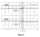
- An exemplary profile of Vbat over time is depicted in Figure 3 .
- the voltage Vbat starts decreasing.
- the processor input voltage VDD starts falling.
- VDD has fallen to a predetermined voltage level such that the voltage supervisor 4 responds and notifies the processor 3.
- the processor 3 starts logging the battery voltage Vbat in the memory 5.
- the battery output voltage Vbat falls from a nominal voltage of 1.3 volts to a reduced voltage of 0.9 volts and remains about that level.
- the voltage converter 6 is able to stabilize the voltage VDD even from the reduced input voltage. As can be seen from Figure 3 , the voltage converter 6 can compensate the drop in the input voltage. At the time T4, the voltage VDD rises above the predetermined voltage level of 2.7 volts. At that time, the processor 3 stops logging Vbat. From the battery voltage Vbat being 0.9 volts at the time T4, it can be determined that the cause of the drop of the processor input voltage VDD was within the battery 2, that is, the battery is of poor quality and has a high internal resistance.
- FIG. 2 shows the profiles of Vbat and VDD for a second event in which the user of the infusion pump 1 removes the battery 2.
- the voltage Vbat rapidly drops from the nominal value of 1.3 volts to a level of (7.5 volts.
- the 0.5 volts level results from an internal buffer capacitor (not shown) in the power supply path. In an unbuffered system, the voltage level would be zero.
- the processor input voltage VDD starts falling.
- the voltage VDD has reached a predetermined level, 2.7 volts in the present example, such that the voltage supervisor 4 responds and notifies the processor 3.
- the processor 3 then starts logging the battery voltage Vbat in the memory 5.
- the voltage converter 6 Since the voltage converter 6 is not able to stabilize its output voltage VDD, it falls beyond a level at which the processor 3 is reset. Form the logged voltage it can be seen that the battery voltage was already low at the time when the logging was started, in particular considerably lower as in the case of a weak battery discussed above with reference to Figure 3 . Therefore, it can be concluded that the battery was not present at that time, i.e., that a misuse has occurred by removing the battery with the device being in operation mode. When the power supply of the device 1 is restored, the processor 3 powers up again. If the time between VDD falling to the reset voltage of the processor 3 and the time at which the processor 3 is powered up again is longer than a predetermined time span, this indicates that the battery 2 was (temporarily) removed.
- This time span can be determined as follows: When the device is powered up, it may run through a self-testing and powering-up sequence of several seconds. After completing the power-up sequence, a corresponding entry is stored in the history memory of the device. If the time between the beginning of the logging, or the last logged value before VDD has fallen to the reset voltage level, and the power-up entry is considerably (i.e. in the range of half a second or more) longer than the time required for powering up, the battery had been removed. Otherwise, the battery was disconnected only for a very short period, e.g., because of a dropping of the device.
- the power supply of the medical infusion pump 1 is interrupted only for a short period of time as shown in Figure 4 , for example if a spring which establishes the electrical contact with an electrode of the battery temporarily disconnects.
- the voltage Vbat sharply drops at a time T1 to the predetermined level at time T5.
- the voltage VDD falls to the reset level of the processor 3 as shown in Figure 4 , so that the processor 3 is reset and powered up again when VDD rises to the reset voltage again at time T7.
- a corresponding entry is stored in the history memory 5 of the device.
- the interruption of the power supply may be so short that VDD does fall below the predetermined voltage, but not to or below the reset voltage of the processor 3. In this case, operation of the device 1 is not impaired. This means that the logged voltage profile can be deleted. As an alternative, the logged voltage profile can be saved for information purposes in this case.
- a drop of the battery voltage Vbat, and therefore of the voltage VDD, can also occur if large currents are drawn from the battery 2 and the battery 2 is weak. This might be the case if the pump is activated while the background light of a display is on. However, the background light and the pump are typically activated for several seconds, such that the time span between the beginning of the logging, or the last logged value before VDD has fallen to the reset voltage level, and the power-up entry is quite long (i.e. in the range of several seconds), and the battery voltage Vbat does not drop as deep as to zero or near zero. Therefore, power interruption caused by large power consumption in combination with a weak battery can also be identified.
Landscapes
- Health & Medical Sciences (AREA)
- General Physics & Mathematics (AREA)
- Physics & Mathematics (AREA)
- Engineering & Computer Science (AREA)
- Biomedical Technology (AREA)
- Veterinary Medicine (AREA)
- Hematology (AREA)
- Life Sciences & Earth Sciences (AREA)
- Animal Behavior & Ethology (AREA)
- General Health & Medical Sciences (AREA)
- Public Health (AREA)
- Heart & Thoracic Surgery (AREA)
- Anesthesiology (AREA)
- Vascular Medicine (AREA)
- Business, Economics & Management (AREA)
- Emergency Management (AREA)
- Power Engineering (AREA)
- Infusion, Injection, And Reservoir Apparatuses (AREA)
- External Artificial Organs (AREA)
Priority Applications (8)
| Application Number | Priority Date | Filing Date | Title |
|---|---|---|---|
| DK09169936T DK2295098T3 (da) | 2009-09-10 | 2009-09-10 | Medicinsk infusionspumpe og fremgangsmåde til bestemmelse af årsagen til en energiafbrydelse i pumpen |
| EP20090169936 EP2295098B1 (de) | 2009-09-10 | 2009-09-10 | Medizinische Infusionspumpe und Verfahren zur Bestimmung der Ursache einer Stromunterbrechung in der Pumpe |
| AT09169936T ATE530213T1 (de) | 2009-09-10 | 2009-09-10 | Medizinische infusionspumpe und verfahren zur bestimmung der ursache einer stromunterbrechung in der pumpe |
| EP10008699.0A EP2295093B1 (de) | 2009-09-10 | 2010-08-20 | Medizinische Infusionspumpe mit Energiequellenspannungserfassung und Verfahren zur Erfassung einer Energiequellenspannung in einer medizinischen Infusionspumpe |
| US12/877,582 US8262617B2 (en) | 2009-09-10 | 2010-09-08 | Medical infusion pump with power source voltage logging and method for logging a power source voltage in a medical infusion pump |
| US13/570,696 US8670836B2 (en) | 2009-09-10 | 2012-08-09 | Medical infusion pump with power source voltage logging and method for logging a power source voltage in a medical infusion pump |
| US14/174,257 US9316700B2 (en) | 2009-09-10 | 2014-02-06 | Medical infusion pump with power source voltage logging and method for logging a power source voltage in a medical infusion pump |
| US15/060,916 US10267865B2 (en) | 2009-09-10 | 2016-03-04 | Portable device with power monitoring to signal battery replacement prior to a voltage supervisor response |
Applications Claiming Priority (1)
| Application Number | Priority Date | Filing Date | Title |
|---|---|---|---|
| EP20090169936 EP2295098B1 (de) | 2009-09-10 | 2009-09-10 | Medizinische Infusionspumpe und Verfahren zur Bestimmung der Ursache einer Stromunterbrechung in der Pumpe |
Publications (2)
| Publication Number | Publication Date |
|---|---|
| EP2295098A1 true EP2295098A1 (de) | 2011-03-16 |
| EP2295098B1 EP2295098B1 (de) | 2011-10-26 |
Family
ID=41791182
Family Applications (2)
| Application Number | Title | Priority Date | Filing Date |
|---|---|---|---|
| EP20090169936 Active EP2295098B1 (de) | 2009-09-10 | 2009-09-10 | Medizinische Infusionspumpe und Verfahren zur Bestimmung der Ursache einer Stromunterbrechung in der Pumpe |
| EP10008699.0A Active EP2295093B1 (de) | 2009-09-10 | 2010-08-20 | Medizinische Infusionspumpe mit Energiequellenspannungserfassung und Verfahren zur Erfassung einer Energiequellenspannung in einer medizinischen Infusionspumpe |
Family Applications After (1)
| Application Number | Title | Priority Date | Filing Date |
|---|---|---|---|
| EP10008699.0A Active EP2295093B1 (de) | 2009-09-10 | 2010-08-20 | Medizinische Infusionspumpe mit Energiequellenspannungserfassung und Verfahren zur Erfassung einer Energiequellenspannung in einer medizinischen Infusionspumpe |
Country Status (4)
| Country | Link |
|---|---|
| US (4) | US8262617B2 (de) |
| EP (2) | EP2295098B1 (de) |
| AT (1) | ATE530213T1 (de) |
| DK (1) | DK2295098T3 (de) |
Cited By (2)
| Publication number | Priority date | Publication date | Assignee | Title |
|---|---|---|---|---|
| US11554209B2 (en) | 2015-05-08 | 2023-01-17 | Triple Jump Israel Ltd. | Systems, apparatuses and methods for fluid infusion into a body |
| US11596733B2 (en) | 2017-06-15 | 2023-03-07 | Triple Jump Israel Ltd. | Patch pump systems and apparatus for managing diabetes, and methods thereof |
Families Citing this family (35)
| Publication number | Priority date | Publication date | Assignee | Title |
|---|---|---|---|---|
| JP5385155B2 (ja) | 2007-02-05 | 2014-01-08 | ボストン サイエンティフィック リミテッド | 血栓除去装置 |
| US20080228056A1 (en) | 2007-03-13 | 2008-09-18 | Michael Blomquist | Basal rate testing using frequent blood glucose input |
| US7751907B2 (en) | 2007-05-24 | 2010-07-06 | Smiths Medical Asd, Inc. | Expert system for insulin pump therapy |
| US8221345B2 (en) | 2007-05-30 | 2012-07-17 | Smiths Medical Asd, Inc. | Insulin pump based expert system |
| US20090177147A1 (en) | 2008-01-07 | 2009-07-09 | Michael Blomquist | Insulin pump with insulin therapy coaching |
| US9510854B2 (en) | 2008-10-13 | 2016-12-06 | Boston Scientific Scimed, Inc. | Thrombectomy catheter with control box having pressure/vacuum valve for synchronous aspiration and fluid irrigation |
| US9211377B2 (en) | 2009-07-30 | 2015-12-15 | Tandem Diabetes Care, Inc. | Infusion pump system with disposable cartridge having pressure venting and pressure feedback |
| DK2295098T3 (da) * | 2009-09-10 | 2012-02-20 | Hoffmann La Roche | Medicinsk infusionspumpe og fremgangsmåde til bestemmelse af årsagen til en energiafbrydelse i pumpen |
| US8882701B2 (en) | 2009-12-04 | 2014-11-11 | Smiths Medical Asd, Inc. | Advanced step therapy delivery for an ambulatory infusion pump and system |
| US8612055B2 (en) * | 2010-04-16 | 2013-12-17 | Medtronic, Inc. | System and method for delivering a therapeutic agent according to default infusion schedule |
| US9940440B2 (en) | 2011-04-28 | 2018-04-10 | Medtronic, Inc. | Detecting and responding to software and hardware anomalies in a fluid delivery system |
| US9180242B2 (en) | 2012-05-17 | 2015-11-10 | Tandem Diabetes Care, Inc. | Methods and devices for multiple fluid transfer |
| US9238100B2 (en) | 2012-06-07 | 2016-01-19 | Tandem Diabetes Care, Inc. | Device and method for training users of ambulatory medical devices |
| US8454557B1 (en) * | 2012-07-19 | 2013-06-04 | Asante Solutions, Inc. | Infusion pump system and method |
| DE102012018799A1 (de) | 2012-09-22 | 2014-03-27 | Dräger Safety AG & Co. KGaA | Versorgungsschaltung in einem Kommunikationssystem einer Kopfschutzbedeckung, Kopfschutzbedeckung mit einer solchen Versorgungsschaltung und Verfahren zum Betrieb einer solchen Versorgungsschaltung |
| RU2641517C2 (ru) * | 2012-09-24 | 2018-01-17 | Конинклейке Филипс Н.В. | Система молокоотсоса с приводом |
| US9173998B2 (en) | 2013-03-14 | 2015-11-03 | Tandem Diabetes Care, Inc. | System and method for detecting occlusions in an infusion pump |
| US9796347B2 (en) * | 2014-01-06 | 2017-10-24 | Union Pacific Railroad Company | Maintenance of a minimum voltage to equipment in rail vehicle |
| US9433427B2 (en) | 2014-04-08 | 2016-09-06 | Incuvate, Llc | Systems and methods for management of thrombosis |
| US9248221B2 (en) | 2014-04-08 | 2016-02-02 | Incuvate, Llc | Aspiration monitoring system and method |
| US9883877B2 (en) | 2014-05-19 | 2018-02-06 | Walk Vascular, Llc | Systems and methods for removal of blood and thrombotic material |
| US9669160B2 (en) | 2014-07-30 | 2017-06-06 | Tandem Diabetes Care, Inc. | Temporary suspension for closed-loop medicament therapy |
| WO2017040317A1 (en) | 2015-08-28 | 2017-03-09 | Thoratec Corporation | Blood pump controllers and methods of use for improved energy efficiency |
| US10702292B2 (en) | 2015-08-28 | 2020-07-07 | Incuvate, Llc | Aspiration monitoring system and method |
| US10561440B2 (en) | 2015-09-03 | 2020-02-18 | Vesatek, Llc | Systems and methods for manipulating medical devices |
| US20170100142A1 (en) | 2015-10-09 | 2017-04-13 | Incuvate, Llc | Systems and methods for management of thrombosis |
| US10226263B2 (en) | 2015-12-23 | 2019-03-12 | Incuvate, Llc | Aspiration monitoring system and method |
| US10569016B2 (en) | 2015-12-29 | 2020-02-25 | Tandem Diabetes Care, Inc. | System and method for switching between closed loop and open loop control of an ambulatory infusion pump |
| US10492805B2 (en) | 2016-04-06 | 2019-12-03 | Walk Vascular, Llc | Systems and methods for thrombolysis and delivery of an agent |
| US20170352246A1 (en) * | 2016-06-06 | 2017-12-07 | SITREP Marine Inc. | Equipment monitoring system and method of its use |
| US10180844B2 (en) * | 2017-01-20 | 2019-01-15 | Oracle International Corporation | Boot path and production path accessible storage system |
| CN111263655B (zh) * | 2017-10-27 | 2024-02-06 | 深圳迈瑞生物医疗电子股份有限公司 | 除颤仪及状态检测管理方法、状态检测管理系统、设备 |
| JP6787945B2 (ja) * | 2018-04-27 | 2020-11-18 | ファナック株式会社 | 機械状態監視装置 |
| US11678905B2 (en) | 2018-07-19 | 2023-06-20 | Walk Vascular, Llc | Systems and methods for removal of blood and thrombotic material |
| US11892520B2 (en) * | 2022-03-28 | 2024-02-06 | Changxin Memory Technologies, Inc. | Method and device for power supply mapping detection, electronic device, and medium |
Citations (6)
| Publication number | Priority date | Publication date | Assignee | Title |
|---|---|---|---|---|
| US5321392A (en) * | 1991-10-18 | 1994-06-14 | Baxter International Inc. | Infusion pump with battery back-up |
| US5764034A (en) * | 1996-04-10 | 1998-06-09 | Baxter International Inc. | Battery gauge for a battery operated infusion pump |
| US5876423A (en) * | 1996-06-04 | 1999-03-02 | Biotronik Mess- Und Therapiegeraete Gmbh & Co. Ingenieurbuero Berlin | Implantable stimulator with terminal voltage control of a depletable voltage source |
| US20020065454A1 (en) * | 2000-01-21 | 2002-05-30 | Lebel Ronald J. | Microprocessor controlled ambulatory medical apparatus with hand held communication device |
| US20070040449A1 (en) * | 2005-08-16 | 2007-02-22 | Medtronic Monimed, Inc. | Method and apparatus for predicting end of battery life |
| US20070293914A1 (en) * | 1999-07-27 | 2007-12-20 | Advanced Bionics Corporation | Patient programmer for implantable devices |
Family Cites Families (15)
| Publication number | Priority date | Publication date | Assignee | Title |
|---|---|---|---|---|
| US4707795A (en) * | 1983-03-14 | 1987-11-17 | Alber Engineering, Inc. | Battery testing and monitoring system |
| US5847587A (en) * | 1997-01-07 | 1998-12-08 | Holtek Microelectronics Inc. | Means for instantaneously detecting abnormal voltage in a micro controller |
| DE69816032D1 (de) * | 1998-04-30 | 2003-08-07 | St Microelectronics Srl | Verfahren zur Sicherung von Daten im Falle unerwünschter Unterbrechnungen während ein Programmzyklus eines nichtflüchtigen Speichers, und ein nichtflüchtiger Speicher |
| US6494827B1 (en) * | 1998-10-29 | 2002-12-17 | Olympus Optical Co., Ltd. | Endoscope device and operation apparatus |
| US7519909B2 (en) * | 2001-08-10 | 2009-04-14 | American Power Conversion Corporation | Uninterruptible power supply (UPS) devices monitoring system |
| WO2003036722A1 (fr) * | 2001-10-26 | 2003-05-01 | Fujitsu Limited | Circuit integre a semi-conducteur, dispositif electronique dans lequel ce circuit integre est incorpore et procede d'economie d'energie |
| JP4201629B2 (ja) * | 2003-03-26 | 2008-12-24 | 三洋電機株式会社 | 誤書込み防止回路および該誤書込み防止回路を含む半導体装置 |
| US8077889B2 (en) * | 2004-01-27 | 2011-12-13 | Phonak Ag | Method to log data in a hearing device as well as a hearing device |
| AU2006218360B2 (en) * | 2005-03-04 | 2011-08-04 | Philadelphia Scientific Llc | Device and method for monitoring life history and controlling maintenance of industrial batteries |
| US7941144B2 (en) * | 2006-05-19 | 2011-05-10 | Telefonaktiebolaget Lm Ericsson (Publ) | Access control in a mobile communication system |
| JP4265629B2 (ja) * | 2006-08-01 | 2009-05-20 | トヨタ自動車株式会社 | 二次電池の充放電制御装置およびそれを搭載したハイブリッド車両 |
| CN101425678B (zh) * | 2007-10-30 | 2011-11-23 | 比亚迪股份有限公司 | 电池保护方法和系统 |
| US7860672B2 (en) * | 2007-12-26 | 2010-12-28 | Elster Electricity, Llc | Method and apparatus for monitoring voltage in a meter network |
| US8331150B2 (en) * | 2008-01-03 | 2012-12-11 | Aplus Flash Technology, Inc. | Integrated SRAM and FLOTOX EEPROM memory device |
| DK2295098T3 (da) * | 2009-09-10 | 2012-02-20 | Hoffmann La Roche | Medicinsk infusionspumpe og fremgangsmåde til bestemmelse af årsagen til en energiafbrydelse i pumpen |
-
2009
- 2009-09-10 DK DK09169936T patent/DK2295098T3/da active
- 2009-09-10 EP EP20090169936 patent/EP2295098B1/de active Active
- 2009-09-10 AT AT09169936T patent/ATE530213T1/de not_active IP Right Cessation
-
2010
- 2010-08-20 EP EP10008699.0A patent/EP2295093B1/de active Active
- 2010-09-08 US US12/877,582 patent/US8262617B2/en active Active
-
2012
- 2012-08-09 US US13/570,696 patent/US8670836B2/en active Active
-
2014
- 2014-02-06 US US14/174,257 patent/US9316700B2/en active Active
-
2016
- 2016-03-04 US US15/060,916 patent/US10267865B2/en active Active
Patent Citations (6)
| Publication number | Priority date | Publication date | Assignee | Title |
|---|---|---|---|---|
| US5321392A (en) * | 1991-10-18 | 1994-06-14 | Baxter International Inc. | Infusion pump with battery back-up |
| US5764034A (en) * | 1996-04-10 | 1998-06-09 | Baxter International Inc. | Battery gauge for a battery operated infusion pump |
| US5876423A (en) * | 1996-06-04 | 1999-03-02 | Biotronik Mess- Und Therapiegeraete Gmbh & Co. Ingenieurbuero Berlin | Implantable stimulator with terminal voltage control of a depletable voltage source |
| US20070293914A1 (en) * | 1999-07-27 | 2007-12-20 | Advanced Bionics Corporation | Patient programmer for implantable devices |
| US20020065454A1 (en) * | 2000-01-21 | 2002-05-30 | Lebel Ronald J. | Microprocessor controlled ambulatory medical apparatus with hand held communication device |
| US20070040449A1 (en) * | 2005-08-16 | 2007-02-22 | Medtronic Monimed, Inc. | Method and apparatus for predicting end of battery life |
Cited By (2)
| Publication number | Priority date | Publication date | Assignee | Title |
|---|---|---|---|---|
| US11554209B2 (en) | 2015-05-08 | 2023-01-17 | Triple Jump Israel Ltd. | Systems, apparatuses and methods for fluid infusion into a body |
| US11596733B2 (en) | 2017-06-15 | 2023-03-07 | Triple Jump Israel Ltd. | Patch pump systems and apparatus for managing diabetes, and methods thereof |
Also Published As
| Publication number | Publication date |
|---|---|
| US8262617B2 (en) | 2012-09-11 |
| EP2295093B1 (de) | 2017-11-29 |
| US20140194848A1 (en) | 2014-07-10 |
| US20120302988A1 (en) | 2012-11-29 |
| US20160199570A1 (en) | 2016-07-14 |
| EP2295098B1 (de) | 2011-10-26 |
| US10267865B2 (en) | 2019-04-23 |
| US9316700B2 (en) | 2016-04-19 |
| US20110060281A1 (en) | 2011-03-10 |
| EP2295093A3 (de) | 2011-08-03 |
| US8670836B2 (en) | 2014-03-11 |
| DK2295098T3 (da) | 2012-02-20 |
| ATE530213T1 (de) | 2011-11-15 |
| EP2295093A2 (de) | 2011-03-16 |
Similar Documents
| Publication | Publication Date | Title |
|---|---|---|
| EP2295098B1 (de) | Medizinische Infusionspumpe und Verfahren zur Bestimmung der Ursache einer Stromunterbrechung in der Pumpe | |
| US8610396B2 (en) | Battery boost apparatus | |
| EP3222320B1 (de) | Adaptiver selbsttest und belastungsanalyse von medizinischen vorrichtungen | |
| US8065004B2 (en) | Method and apparatus for automatic self-test of medical device | |
| EP2564485B1 (de) | Detektionsverfahren und -systeme für das vorhandensein einer batterie | |
| US20140103955A1 (en) | System and method for automated failure detection of hold-up power storage devices | |
| EP2887085A1 (de) | Verfahren und Vorrichtung zur Anzeige eines niedrigen Batteriestands | |
| JP2011036046A (ja) | 電源バックアップ装置 | |
| US20200158785A1 (en) | Medical device with battery testing | |
| CN108984330B (zh) | 一种控制存储设备的方法、装置及电子设备 | |
| US11404862B2 (en) | Method, control unit, and electrical network | |
| JP5085054B2 (ja) | 電池残量モニタ装置 | |
| CN108087136B (zh) | 一种泵油控制方法及装置 | |
| CN112616012B (zh) | 一种监控设备的控制方法及监控设备 | |
| CN112684738B (zh) | 设备控制方法、装置及电池模块、非易失性存储介质 | |
| US20170331028A1 (en) | Method and apparatus for shake awake smart battery pack | |
| CN112673539B (zh) | 一种电源设备及在该电源设备处管理dc功率的方法 | |
| CN116620101A (zh) | 一种电池检测方法、装置、设备及存储介质 | |
| CN117031335A (zh) | 一种电池老化安全监测系统 | |
| CN117630708A (zh) | 电池危险检测 | |
| JP2004266947A (ja) | 安定化電源装置 | |
| KR20090010482A (ko) | 전자기기 가동 제어 방법 |
Legal Events
| Date | Code | Title | Description |
|---|---|---|---|
| PUAI | Public reference made under article 153(3) epc to a published international application that has entered the european phase |
Free format text: ORIGINAL CODE: 0009012 |
|
| 17P | Request for examination filed |
Effective date: 20100517 |
|
| AK | Designated contracting states |
Kind code of ref document: A1 Designated state(s): AT BE BG CH CY CZ DE DK EE ES FI FR GB GR HR HU IE IS IT LI LT LU LV MC MK MT NL NO PL PT RO SE SI SK SM TR |
|
| GRAP | Despatch of communication of intention to grant a patent |
Free format text: ORIGINAL CODE: EPIDOSNIGR1 |
|
| GRAS | Grant fee paid |
Free format text: ORIGINAL CODE: EPIDOSNIGR3 |
|
| GRAA | (expected) grant |
Free format text: ORIGINAL CODE: 0009210 |
|
| AK | Designated contracting states |
Kind code of ref document: B1 Designated state(s): AT BE BG CH CY CZ DE DK EE ES FI FR GB GR HR HU IE IS IT LI LT LU LV MC MK MT NL NO PL PT RO SE SI SK SM TR |
|
| REG | Reference to a national code |
Ref country code: GB Ref legal event code: FG4D |
|
| REG | Reference to a national code |
Ref country code: CH Ref legal event code: NV Representative=s name: RIEDERER HASLER & PARTNER PATENTANWAELTE AG Ref country code: CH Ref legal event code: EP |
|
| REG | Reference to a national code |
Ref country code: IE Ref legal event code: FG4D |
|
| REG | Reference to a national code |
Ref country code: NL Ref legal event code: T3 |
|
| REG | Reference to a national code |
Ref country code: DE Ref legal event code: R096 Ref document number: 602009003283 Country of ref document: DE Effective date: 20120105 |
|
| REG | Reference to a national code |
Ref country code: DK Ref legal event code: T3 |
|
| LTIE | Lt: invalidation of european patent or patent extension |
Effective date: 20111026 |
|
| REG | Reference to a national code |
Ref country code: AT Ref legal event code: MK05 Ref document number: 530213 Country of ref document: AT Kind code of ref document: T Effective date: 20111026 |
|
| PG25 | Lapsed in a contracting state [announced via postgrant information from national office to epo] |
Ref country code: BE Free format text: LAPSE BECAUSE OF FAILURE TO SUBMIT A TRANSLATION OF THE DESCRIPTION OR TO PAY THE FEE WITHIN THE PRESCRIBED TIME-LIMIT Effective date: 20111026 Ref country code: IS Free format text: LAPSE BECAUSE OF FAILURE TO SUBMIT A TRANSLATION OF THE DESCRIPTION OR TO PAY THE FEE WITHIN THE PRESCRIBED TIME-LIMIT Effective date: 20120226 Ref country code: LT Free format text: LAPSE BECAUSE OF FAILURE TO SUBMIT A TRANSLATION OF THE DESCRIPTION OR TO PAY THE FEE WITHIN THE PRESCRIBED TIME-LIMIT Effective date: 20111026 Ref country code: NO Free format text: LAPSE BECAUSE OF FAILURE TO SUBMIT A TRANSLATION OF THE DESCRIPTION OR TO PAY THE FEE WITHIN THE PRESCRIBED TIME-LIMIT Effective date: 20120126 |
|
| PG25 | Lapsed in a contracting state [announced via postgrant information from national office to epo] |
Ref country code: PL Free format text: LAPSE BECAUSE OF FAILURE TO SUBMIT A TRANSLATION OF THE DESCRIPTION OR TO PAY THE FEE WITHIN THE PRESCRIBED TIME-LIMIT Effective date: 20111026 Ref country code: LV Free format text: LAPSE BECAUSE OF FAILURE TO SUBMIT A TRANSLATION OF THE DESCRIPTION OR TO PAY THE FEE WITHIN THE PRESCRIBED TIME-LIMIT Effective date: 20111026 Ref country code: PT Free format text: LAPSE BECAUSE OF FAILURE TO SUBMIT A TRANSLATION OF THE DESCRIPTION OR TO PAY THE FEE WITHIN THE PRESCRIBED TIME-LIMIT Effective date: 20120227 Ref country code: HR Free format text: LAPSE BECAUSE OF FAILURE TO SUBMIT A TRANSLATION OF THE DESCRIPTION OR TO PAY THE FEE WITHIN THE PRESCRIBED TIME-LIMIT Effective date: 20111026 Ref country code: GR Free format text: LAPSE BECAUSE OF FAILURE TO SUBMIT A TRANSLATION OF THE DESCRIPTION OR TO PAY THE FEE WITHIN THE PRESCRIBED TIME-LIMIT Effective date: 20120127 Ref country code: SE Free format text: LAPSE BECAUSE OF FAILURE TO SUBMIT A TRANSLATION OF THE DESCRIPTION OR TO PAY THE FEE WITHIN THE PRESCRIBED TIME-LIMIT Effective date: 20111026 Ref country code: SI Free format text: LAPSE BECAUSE OF FAILURE TO SUBMIT A TRANSLATION OF THE DESCRIPTION OR TO PAY THE FEE WITHIN THE PRESCRIBED TIME-LIMIT Effective date: 20111026 |
|
| PG25 | Lapsed in a contracting state [announced via postgrant information from national office to epo] |
Ref country code: CY Free format text: LAPSE BECAUSE OF FAILURE TO SUBMIT A TRANSLATION OF THE DESCRIPTION OR TO PAY THE FEE WITHIN THE PRESCRIBED TIME-LIMIT Effective date: 20111026 |
|
| PG25 | Lapsed in a contracting state [announced via postgrant information from national office to epo] |
Ref country code: SK Free format text: LAPSE BECAUSE OF FAILURE TO SUBMIT A TRANSLATION OF THE DESCRIPTION OR TO PAY THE FEE WITHIN THE PRESCRIBED TIME-LIMIT Effective date: 20111026 Ref country code: BG Free format text: LAPSE BECAUSE OF FAILURE TO SUBMIT A TRANSLATION OF THE DESCRIPTION OR TO PAY THE FEE WITHIN THE PRESCRIBED TIME-LIMIT Effective date: 20120126 Ref country code: CZ Free format text: LAPSE BECAUSE OF FAILURE TO SUBMIT A TRANSLATION OF THE DESCRIPTION OR TO PAY THE FEE WITHIN THE PRESCRIBED TIME-LIMIT Effective date: 20111026 Ref country code: EE Free format text: LAPSE BECAUSE OF FAILURE TO SUBMIT A TRANSLATION OF THE DESCRIPTION OR TO PAY THE FEE WITHIN THE PRESCRIBED TIME-LIMIT Effective date: 20111026 |
|
| PG25 | Lapsed in a contracting state [announced via postgrant information from national office to epo] |
Ref country code: IT Free format text: LAPSE BECAUSE OF FAILURE TO SUBMIT A TRANSLATION OF THE DESCRIPTION OR TO PAY THE FEE WITHIN THE PRESCRIBED TIME-LIMIT Effective date: 20111026 Ref country code: RO Free format text: LAPSE BECAUSE OF FAILURE TO SUBMIT A TRANSLATION OF THE DESCRIPTION OR TO PAY THE FEE WITHIN THE PRESCRIBED TIME-LIMIT Effective date: 20111026 |
|
| PLBE | No opposition filed within time limit |
Free format text: ORIGINAL CODE: 0009261 |
|
| STAA | Information on the status of an ep patent application or granted ep patent |
Free format text: STATUS: NO OPPOSITION FILED WITHIN TIME LIMIT |
|
| 26N | No opposition filed |
Effective date: 20120727 |
|
| REG | Reference to a national code |
Ref country code: DE Ref legal event code: R097 Ref document number: 602009003283 Country of ref document: DE Effective date: 20120727 |
|
| PG25 | Lapsed in a contracting state [announced via postgrant information from national office to epo] |
Ref country code: AT Free format text: LAPSE BECAUSE OF FAILURE TO SUBMIT A TRANSLATION OF THE DESCRIPTION OR TO PAY THE FEE WITHIN THE PRESCRIBED TIME-LIMIT Effective date: 20111026 |
|
| PG25 | Lapsed in a contracting state [announced via postgrant information from national office to epo] |
Ref country code: MC Free format text: LAPSE BECAUSE OF NON-PAYMENT OF DUE FEES Effective date: 20120930 Ref country code: ES Free format text: LAPSE BECAUSE OF FAILURE TO SUBMIT A TRANSLATION OF THE DESCRIPTION OR TO PAY THE FEE WITHIN THE PRESCRIBED TIME-LIMIT Effective date: 20120206 |
|
| REG | Reference to a national code |
Ref country code: IE Ref legal event code: MM4A |
|
| PG25 | Lapsed in a contracting state [announced via postgrant information from national office to epo] |
Ref country code: FI Free format text: LAPSE BECAUSE OF FAILURE TO SUBMIT A TRANSLATION OF THE DESCRIPTION OR TO PAY THE FEE WITHIN THE PRESCRIBED TIME-LIMIT Effective date: 20111026 |
|
| PG25 | Lapsed in a contracting state [announced via postgrant information from national office to epo] |
Ref country code: IE Free format text: LAPSE BECAUSE OF NON-PAYMENT OF DUE FEES Effective date: 20120910 |
|
| PG25 | Lapsed in a contracting state [announced via postgrant information from national office to epo] |
Ref country code: MT Free format text: LAPSE BECAUSE OF FAILURE TO SUBMIT A TRANSLATION OF THE DESCRIPTION OR TO PAY THE FEE WITHIN THE PRESCRIBED TIME-LIMIT Effective date: 20111026 |
|
| PG25 | Lapsed in a contracting state [announced via postgrant information from national office to epo] |
Ref country code: TR Free format text: LAPSE BECAUSE OF FAILURE TO SUBMIT A TRANSLATION OF THE DESCRIPTION OR TO PAY THE FEE WITHIN THE PRESCRIBED TIME-LIMIT Effective date: 20111026 |
|
| GBPC | Gb: european patent ceased through non-payment of renewal fee |
Effective date: 20130910 |
|
| PG25 | Lapsed in a contracting state [announced via postgrant information from national office to epo] |
Ref country code: SM Free format text: LAPSE BECAUSE OF FAILURE TO SUBMIT A TRANSLATION OF THE DESCRIPTION OR TO PAY THE FEE WITHIN THE PRESCRIBED TIME-LIMIT Effective date: 20111026 Ref country code: LU Free format text: LAPSE BECAUSE OF NON-PAYMENT OF DUE FEES Effective date: 20120910 |
|
| PG25 | Lapsed in a contracting state [announced via postgrant information from national office to epo] |
Ref country code: HU Free format text: LAPSE BECAUSE OF FAILURE TO SUBMIT A TRANSLATION OF THE DESCRIPTION OR TO PAY THE FEE WITHIN THE PRESCRIBED TIME-LIMIT Effective date: 20090910 Ref country code: GB Free format text: LAPSE BECAUSE OF NON-PAYMENT OF DUE FEES Effective date: 20130910 |
|
| REG | Reference to a national code |
Ref country code: FR Ref legal event code: PLFP Year of fee payment: 7 |
|
| PG25 | Lapsed in a contracting state [announced via postgrant information from national office to epo] |
Ref country code: MK Free format text: LAPSE BECAUSE OF FAILURE TO SUBMIT A TRANSLATION OF THE DESCRIPTION OR TO PAY THE FEE WITHIN THE PRESCRIBED TIME-LIMIT Effective date: 20111026 |
|
| REG | Reference to a national code |
Ref country code: FR Ref legal event code: PLFP Year of fee payment: 8 |
|
| REG | Reference to a national code |
Ref country code: FR Ref legal event code: PLFP Year of fee payment: 9 |
|
| REG | Reference to a national code |
Ref country code: FR Ref legal event code: PLFP Year of fee payment: 10 |
|
| REG | Reference to a national code |
Ref country code: DE Ref legal event code: R082 Ref document number: 602009003283 Country of ref document: DE Ref country code: DE Ref legal event code: R081 Ref document number: 602009003283 Country of ref document: DE Owner name: ROCHE DIABETES CARE GMBH, DE Free format text: FORMER OWNER: ROCHE DIAGNOSTICS GMBH, 68305 MANNHEIM, DE |
|
| PGFP | Annual fee paid to national office [announced via postgrant information from national office to epo] |
Ref country code: NL Payment date: 20230822 Year of fee payment: 15 |
|
| PGFP | Annual fee paid to national office [announced via postgrant information from national office to epo] |
Ref country code: FR Payment date: 20230822 Year of fee payment: 15 Ref country code: DK Payment date: 20230822 Year of fee payment: 15 Ref country code: DE Payment date: 20230822 Year of fee payment: 15 |
|
| PGFP | Annual fee paid to national office [announced via postgrant information from national office to epo] |
Ref country code: CH Payment date: 20231001 Year of fee payment: 15 |