EP2295093A2 - Medizinische Infusionspumpe mit Energiequellenspannungserfassung und Verfahren zur Erfassung einer Energiequellenspannung in einer medizinischen Infusionspumpe - Google Patents
Medizinische Infusionspumpe mit Energiequellenspannungserfassung und Verfahren zur Erfassung einer Energiequellenspannung in einer medizinischen Infusionspumpe Download PDFInfo
- Publication number
- EP2295093A2 EP2295093A2 EP20100008699 EP10008699A EP2295093A2 EP 2295093 A2 EP2295093 A2 EP 2295093A2 EP 20100008699 EP20100008699 EP 20100008699 EP 10008699 A EP10008699 A EP 10008699A EP 2295093 A2 EP2295093 A2 EP 2295093A2
- Authority
- EP
- European Patent Office
- Prior art keywords
- voltage
- processor
- power source
- infusion pump
- medical infusion
- Prior art date
- Legal status (The legal status is an assumption and is not a legal conclusion. Google has not performed a legal analysis and makes no representation as to the accuracy of the status listed.)
- Granted
Links
- 238000001802 infusion Methods 0.000 title claims abstract description 102
- 238000000034 method Methods 0.000 title claims abstract description 18
- 230000004044 response Effects 0.000 claims abstract description 41
- 230000015654 memory Effects 0.000 claims abstract description 39
- 238000012360 testing method Methods 0.000 claims description 10
- 239000003814 drug Substances 0.000 claims description 7
- 230000008859 change Effects 0.000 claims description 5
- 239000003550 marker Substances 0.000 claims description 5
- 238000013459 approach Methods 0.000 claims description 4
- 238000012544 monitoring process Methods 0.000 claims description 4
- 230000007547 defect Effects 0.000 abstract 1
- NOESYZHRGYRDHS-UHFFFAOYSA-N insulin Chemical compound N1C(=O)C(NC(=O)C(CCC(N)=O)NC(=O)C(CCC(O)=O)NC(=O)C(C(C)C)NC(=O)C(NC(=O)CN)C(C)CC)CSSCC(C(NC(CO)C(=O)NC(CC(C)C)C(=O)NC(CC=2C=CC(O)=CC=2)C(=O)NC(CCC(N)=O)C(=O)NC(CC(C)C)C(=O)NC(CCC(O)=O)C(=O)NC(CC(N)=O)C(=O)NC(CC=2C=CC(O)=CC=2)C(=O)NC(CSSCC(NC(=O)C(C(C)C)NC(=O)C(CC(C)C)NC(=O)C(CC=2C=CC(O)=CC=2)NC(=O)C(CC(C)C)NC(=O)C(C)NC(=O)C(CCC(O)=O)NC(=O)C(C(C)C)NC(=O)C(CC(C)C)NC(=O)C(CC=2NC=NC=2)NC(=O)C(CO)NC(=O)CNC2=O)C(=O)NCC(=O)NC(CCC(O)=O)C(=O)NC(CCCNC(N)=N)C(=O)NCC(=O)NC(CC=3C=CC=CC=3)C(=O)NC(CC=3C=CC=CC=3)C(=O)NC(CC=3C=CC(O)=CC=3)C(=O)NC(C(C)O)C(=O)N3C(CCC3)C(=O)NC(CCCCN)C(=O)NC(C)C(O)=O)C(=O)NC(CC(N)=O)C(O)=O)=O)NC(=O)C(C(C)CC)NC(=O)C(CO)NC(=O)C(C(C)O)NC(=O)C1CSSCC2NC(=O)C(CC(C)C)NC(=O)C(NC(=O)C(CCC(N)=O)NC(=O)C(CC(N)=O)NC(=O)C(NC(=O)C(N)CC=1C=CC=CC=1)C(C)C)CC1=CN=CN1 NOESYZHRGYRDHS-UHFFFAOYSA-N 0.000 description 28
- 102000004877 Insulin Human genes 0.000 description 14
- 108090001061 Insulin Proteins 0.000 description 14
- 229940125396 insulin Drugs 0.000 description 14
- 238000011156 evaluation Methods 0.000 description 6
- 230000002349 favourable effect Effects 0.000 description 5
- 206010012601 diabetes mellitus Diseases 0.000 description 4
- 230000000694 effects Effects 0.000 description 4
- 230000006870 function Effects 0.000 description 4
- 238000012423 maintenance Methods 0.000 description 4
- 238000005070 sampling Methods 0.000 description 4
- 239000003990 capacitor Substances 0.000 description 3
- 238000005265 energy consumption Methods 0.000 description 3
- 230000035939 shock Effects 0.000 description 3
- 238000007920 subcutaneous administration Methods 0.000 description 3
- 238000002560 therapeutic procedure Methods 0.000 description 3
- 101001005269 Arabidopsis thaliana Ceramide synthase 1 LOH3 Proteins 0.000 description 2
- 101001005312 Arabidopsis thaliana Ceramide synthase LOH1 Proteins 0.000 description 2
- 101001089091 Cytisus scoparius 2-acetamido-2-deoxy-D-galactose-binding seed lectin 2 Proteins 0.000 description 2
- 230000003044 adaptive effect Effects 0.000 description 2
- 230000008901 benefit Effects 0.000 description 2
- 230000007423 decrease Effects 0.000 description 2
- 230000003247 decreasing effect Effects 0.000 description 2
- 238000010586 diagram Methods 0.000 description 2
- 230000006641 stabilisation Effects 0.000 description 2
- 238000011105 stabilization Methods 0.000 description 2
- WQZGKKKJIJFFOK-GASJEMHNSA-N Glucose Natural products OC[C@H]1OC(O)[C@H](O)[C@@H](O)[C@@H]1O WQZGKKKJIJFFOK-GASJEMHNSA-N 0.000 description 1
- 230000003213 activating effect Effects 0.000 description 1
- 239000008280 blood Substances 0.000 description 1
- 210000004369 blood Anatomy 0.000 description 1
- 235000019504 cigarettes Nutrition 0.000 description 1
- 230000008878 coupling Effects 0.000 description 1
- 238000010168 coupling process Methods 0.000 description 1
- 238000005859 coupling reaction Methods 0.000 description 1
- 238000013075 data extraction Methods 0.000 description 1
- 230000002950 deficient Effects 0.000 description 1
- 230000001419 dependent effect Effects 0.000 description 1
- 238000009795 derivation Methods 0.000 description 1
- 238000013461 design Methods 0.000 description 1
- 238000003745 diagnosis Methods 0.000 description 1
- 238000004146 energy storage Methods 0.000 description 1
- 239000000446 fuel Substances 0.000 description 1
- 239000008103 glucose Substances 0.000 description 1
- 230000001771 impaired effect Effects 0.000 description 1
- 230000007257 malfunction Effects 0.000 description 1
- 235000012054 meals Nutrition 0.000 description 1
- 230000008569 process Effects 0.000 description 1
- 238000012545 processing Methods 0.000 description 1
- 230000009467 reduction Effects 0.000 description 1
- 230000000087 stabilizing effect Effects 0.000 description 1
- 230000002277 temperature effect Effects 0.000 description 1
- 230000000007 visual effect Effects 0.000 description 1
Images


Classifications
-
- G—PHYSICS
- G01—MEASURING; TESTING
- G01R—MEASURING ELECTRIC VARIABLES; MEASURING MAGNETIC VARIABLES
- G01R31/00—Arrangements for testing electric properties; Arrangements for locating electric faults; Arrangements for electrical testing characterised by what is being tested not provided for elsewhere
- G01R31/40—Testing power supplies
-
- A—HUMAN NECESSITIES
- A61—MEDICAL OR VETERINARY SCIENCE; HYGIENE
- A61M—DEVICES FOR INTRODUCING MEDIA INTO, OR ONTO, THE BODY; DEVICES FOR TRANSDUCING BODY MEDIA OR FOR TAKING MEDIA FROM THE BODY; DEVICES FOR PRODUCING OR ENDING SLEEP OR STUPOR
- A61M5/00—Devices for bringing media into the body in a subcutaneous, intra-vascular or intramuscular way; Accessories therefor, e.g. filling or cleaning devices, arm-rests
- A61M5/14—Infusion devices, e.g. infusing by gravity; Blood infusion; Accessories therefor
- A61M5/142—Pressure infusion, e.g. using pumps
- A61M5/14244—Pressure infusion, e.g. using pumps adapted to be carried by the patient, e.g. portable on the body
-
- G—PHYSICS
- G01—MEASURING; TESTING
- G01R—MEASURING ELECTRIC VARIABLES; MEASURING MAGNETIC VARIABLES
- G01R31/00—Arrangements for testing electric properties; Arrangements for locating electric faults; Arrangements for electrical testing characterised by what is being tested not provided for elsewhere
- G01R31/36—Arrangements for testing, measuring or monitoring the electrical condition of accumulators or electric batteries, e.g. capacity or state of charge [SoC]
- G01R31/3644—Constructional arrangements
-
- G—PHYSICS
- G08—SIGNALLING
- G08B—SIGNALLING OR CALLING SYSTEMS; ORDER TELEGRAPHS; ALARM SYSTEMS
- G08B21/00—Alarms responsive to a single specified undesired or abnormal condition and not otherwise provided for
- G08B21/18—Status alarms
- G08B21/182—Level alarms, e.g. alarms responsive to variables exceeding a threshold
-
- H—ELECTRICITY
- H02—GENERATION; CONVERSION OR DISTRIBUTION OF ELECTRIC POWER
- H02J—CIRCUIT ARRANGEMENTS OR SYSTEMS FOR SUPPLYING OR DISTRIBUTING ELECTRIC POWER; SYSTEMS FOR STORING ELECTRIC ENERGY
- H02J9/00—Circuit arrangements for emergency or stand-by power supply, e.g. for emergency lighting
- H02J9/04—Circuit arrangements for emergency or stand-by power supply, e.g. for emergency lighting in which the distribution system is disconnected from the normal source and connected to a standby source
- H02J9/06—Circuit arrangements for emergency or stand-by power supply, e.g. for emergency lighting in which the distribution system is disconnected from the normal source and connected to a standby source with automatic change-over, e.g. UPS systems
- H02J9/061—Circuit arrangements for emergency or stand-by power supply, e.g. for emergency lighting in which the distribution system is disconnected from the normal source and connected to a standby source with automatic change-over, e.g. UPS systems for DC powered loads
-
- A—HUMAN NECESSITIES
- A61—MEDICAL OR VETERINARY SCIENCE; HYGIENE
- A61M—DEVICES FOR INTRODUCING MEDIA INTO, OR ONTO, THE BODY; DEVICES FOR TRANSDUCING BODY MEDIA OR FOR TAKING MEDIA FROM THE BODY; DEVICES FOR PRODUCING OR ENDING SLEEP OR STUPOR
- A61M2205/00—General characteristics of the apparatus
- A61M2205/18—General characteristics of the apparatus with alarm
-
- A—HUMAN NECESSITIES
- A61—MEDICAL OR VETERINARY SCIENCE; HYGIENE
- A61M—DEVICES FOR INTRODUCING MEDIA INTO, OR ONTO, THE BODY; DEVICES FOR TRANSDUCING BODY MEDIA OR FOR TAKING MEDIA FROM THE BODY; DEVICES FOR PRODUCING OR ENDING SLEEP OR STUPOR
- A61M2205/00—General characteristics of the apparatus
- A61M2205/82—Internal energy supply devices
- A61M2205/8206—Internal energy supply devices battery-operated
-
- G—PHYSICS
- G01—MEASURING; TESTING
- G01R—MEASURING ELECTRIC VARIABLES; MEASURING MAGNETIC VARIABLES
- G01R31/00—Arrangements for testing electric properties; Arrangements for locating electric faults; Arrangements for electrical testing characterised by what is being tested not provided for elsewhere
- G01R31/36—Arrangements for testing, measuring or monitoring the electrical condition of accumulators or electric batteries, e.g. capacity or state of charge [SoC]
- G01R31/396—Acquisition or processing of data for testing or for monitoring individual cells or groups of cells within a battery
-
- Y—GENERAL TAGGING OF NEW TECHNOLOGICAL DEVELOPMENTS; GENERAL TAGGING OF CROSS-SECTIONAL TECHNOLOGIES SPANNING OVER SEVERAL SECTIONS OF THE IPC; TECHNICAL SUBJECTS COVERED BY FORMER USPC CROSS-REFERENCE ART COLLECTIONS [XRACs] AND DIGESTS
- Y10—TECHNICAL SUBJECTS COVERED BY FORMER USPC
- Y10T—TECHNICAL SUBJECTS COVERED BY FORMER US CLASSIFICATION
- Y10T29/00—Metal working
- Y10T29/49—Method of mechanical manufacture
- Y10T29/49718—Repairing
- Y10T29/49721—Repairing with disassembling
- Y10T29/4973—Replacing of defective part
Definitions
- the present disclosure relates to a medical infusion pump, in particular to an ambulatory medical infusion pump, and a method for a logging power source voltage of a power supply provided by a power source in the medical infusion pump.
- Such infusion pumps can be, for example, insulin pumps, in particular worn by a person continuously night and day.
- the medical infusion pump may be designed to be carried by a user substantially continuously and concealed from view.
- the medical infusion pump may have a size of about a cigarette packet or less and be designed to be carried in a belt holster, in a trouser's pocket, in a necklace-like way, or the like, and to be coupled with a subcutaneous infusion cannula via a tubing of, e.g., 0.3m to 1.5m length.
- the pump may include a subcutaneous infusion cannula and be directly adhesively attached to the skin at the infusion site.
- the medical infusion pump may be designed to infuse medicine in accordance with a quasi-continuous and time-variable infusion profile.
- a pump may be used, for example in the therapy of diabetes mellitus by quasi-continuous subcutaneous insulin infusion, CSII.
- CSII quasi-continuous subcutaneous insulin infusion
- insulin is subcutaneously infused into a diabetic's body in accordance with the diabetic's personal and time-varying basal insulin demands.
- Such a pump may further be designed to infuse additional medicine insulin boli on demand, for example insulin boli to cover the intake of carbohydrate-comprising meals.
- Medical devices like medical infusion pumps are typically powered by an electrical power source, typically a rechargeable or non-rechargeable battery, such as a common AA or AAA cell or a special-purpose power pack.
- the medical infusion pump typically comprises a housing with a user-accessible compartment or interface for holding or attaching the power source in a replaceable way.
- Those devices typically further comprise at least one processor, for example in form of an ASIC or microcontroller, which controls the device operation.
- a failure occurs if the voltage provided by the power source to the medical device or specific components within the medical device drops to a critical value, which is also called a reset voltage level because further operation is not possible and a reset of the medical device or a specific component within the medical device, in particular the processor, is performed at this voltage level. This results in the device sopping, at least temporarily, to operate as intended.
- a medical infusion pump typically terminates infusion. In some cases, the user, for example a diabetic, may not even become immediately aware of this potentially dangerous situation.
- the objective is achieved based on the insight that the reason for such a power supply interruption may be determined by analyzing the power source voltage as a function of time at and shortly before the interruption.
- determining the cause of a power supply interruption is, at least partly, carried out by the infusion pump itself.
- the device provides the data that allow a technical expert to carry out the analysis.
- Typical scenarios for a power supply interruption are in the following discussed in some more detail. If the power source is suddenly removed, the power source voltage rapidly falls to zero or near zero and remains there. The voltage may fall to near zero instead of zero if there is a capacitor present in parallel to the battery.
- the residual voltage level which falls under the term “near zero", can have levels of up to 0.5 volts, for example.
- the infusion pump may include one or more contact springs for electrically connecting the power source in a releasable way. If the medical device is dropped, such that the contacts temporarily detach, there is a steep notch in the power source voltage to zero or near zero for a short period of time, resulting in a reset of the processor, followed by a subsequent power-up.
- Diabetics are known, for example, to occasionally push an insulin pump onto a table in order to remove air bubbles from an insulin cartridge in a cartridge compartment of the pump.
- the term "dropping" generally covers mechanical shocks that have substantially effect as the medical infusion pump being dropped.
- a power source is removed by the user during normal operation of the device.
- a power-up only occurs when the same or a new battery is connected.
- normal operation refers to an operational mode where the medical infusion pump operates as intended.
- An insulin pump for example, may infuse insulin in a quasi-continuous way as described above in a normal operation mode.
- a further example for a device-internal error is a loose contact to the power supply which may result in a number of repeated interruptions of the power supply.
- a power source voltage that is logged when the processor supply voltage drops to the reset voltage level is to be understood in the sense of the last logged value before the processor stops logging because the processor supply voltage has reached or fallen below the reset voltage level.
- a dropping voltage does not necessary stop dropping at a specified level. "Dropping to a level” therefore has to be understood in the sense of assuming and typically falling below that level.
- the US 5764034 discloses a battery gauge for a battery operated infusion pump as well as formulas for calculating a remaining battery lifetime based on six stored voltage values, each of which represents an average of several voltage samples.
- the US 2007/0293914 A1 discloses a system and a corresponding method for determining the status of a rechargeable battery in an implantable medical device with the battery voltage being measured with a predetermined time interval, e.g. four hours and e.g. every 10 sec. after the battery voltage falling below a specified minimum level.
- a medical infusion pump comprises a power source, a processor and a voltage supervisor with the power source powering the processor.
- the voltage supervisor is configured to monitor the processor supply voltage and the voltage supervisor is further configured to respond if this voltage drops to a predetermined response voltage level above the reset voltage level of the processor.
- the response voltage level may be adaptive and be selected, for example, in dependence of the power source type, the temperature, and further factors.
- the processor can, as generally known in the art, be any central processing unit (CPU) or any microprocessor, microcontroller or ASIC, or combination of those, including discrete circuitry.
- the battery can be a single-use battery or rechargeable battery, for example.
- responding of the supervisor means that the supervisor provides an output signal which indicates that the voltage has dropped to the response voltage level.
- Such a supervisor continuously compares the processor supply voltage with an internal reference level. Continuous operation is necessary because a power supply interruption, caused, e.g., by a drop, may occur at any time.
- reset means a process where the processor terminates operation when the processor supply voltage reaches and falls below the reset voltage.
- the processor stays non-operable as long as the processor supply voltage is not present or below the reset voltage level. As the processor supply voltage passes the reset voltage level and exceeds it, the processor starts operating again in a pre-defined reset state. The latter phase is also referred to as "powering up" the processor.
- the voltage supervisor may be external to the processor, an internal component of the processor or a functionality of the processor, for example using an internal A/D (analogue-to-digital) converter and logic circuitry, or any combination of those.
- the processor is configured to start logging the voltage of the power source to a memory, thus creating voltage log as profile of the voltage over time, when the voltage supervisor responds.
- the logging is carried out with a sufficiently high sampling rate to ensure that a number of values are logged before the voltage drops to the reset voltage level and the processor stops operation. It is typically in the range of some kHz.
- the memory is a favorably a non-volatile memory RAM (random access memory) that is designed to maintain stored data in the absence of a supply voltage. In principle, however, it may also be a volatile memory which is powered by an independent power supply. Because the data are maintained in the memory, retrospective analysis of the power log is enabled. The memory is typically also powered by the power source.
- the logged data can be analyzed using an external device which is configured to receive the logged data from the medical infusion pump to determine the cause of an interruption of the power supply to the processor from the logged power source voltage. After transmitting the data to the external device, they may be analyzed, evaluated and potentially stored, e.g., for liability reasons, by a medical expert and/or by automated system.
- a data interface for transmitting the logged data to the external device, such as a standard personal computer or a dedicated diagnosis device, a data interface, in particular a wireless data interface such as an IR (infra-red) interface or RF (radio frequency) interface, e.g., based on the Bluetooth standard, may be present in the infusion device.
- a data interface may also be used for additional purposes, for exampling remote-controlling the infusion pump during normal operation.
- a technical expert can accordingly evaluate the logged power source voltage profile shortly before the reset and determine the course of the interruption from the log by evaluating characteristic data, such as the power source voltage when the processor supply voltage reaches the reset voltage level, with corresponding characteristic data for different courses of the interruption.
- characteristic data such as the power source voltage when the processor supply voltage reaches the reset voltage level
- characteristic data for different courses of the interruption.
- the voltage log itself that is, the power source voltage as a function of time, is compared with corresponding characteristic reference profiles manually by visual and/ or automated comparison.
- this evaluation or analysis is, completely or partly, carried out by the infusion pump itself and the result is favourably displayed and stored. Since the stored voltage log is maintained during the power supply interruption, this analysis or evaluation can be, manually or automatically, carried out retrospectively, for example after the next following power-up.
- the memory of the medical infusion pump may be configured to permanently store the voltage log and/or characteristic data that are extracted or determined from the voltage log.
- Periodently storing refers to the stored data being maintained during all situations that may typically occur during usage of the pump, including replacing the power source or removing the power source for an extended time periods of, e.g., several weeks or months. It may, however, be possible for those data to be cleared, for example by a technical expert, typically following transferring the data to an external device as described above and/or analyzing the cause of the power supply interruption.
- the voltage log as such is stored for later evaluation. As will become more readily apparent as the description proceeds, it may, however, be sufficient to store only a number of characteristic data that is extracted or computed from the voltage log and reflects the cause of a power supply interruption. While being associated with a loss of information, it is favourable with respect to memory demand.
- the response voltage level of the voltage supervisor is above the reset voltage level of the processor. In the time span between those two events, the processor is able to log the power source voltage. In general, the response voltage level is below a minimum typical voltage level which may occur during normal operation of the device due to general variation, temperature effects, etc., but above the reset voltage level of the processor. A voltage level below response voltage level but still above the reset voltage level may, however, occur sporadically during normal operation, for example in a situation where an extraordinarily high current is drawn by the infusion pump and the temperature is low. In particular, the voltage supervisor may respond at a level that is about 0.1 volts to 0.2 volts above the reset voltage level. As will be discussed below, the processor supply voltage is typically not identical to the power source voltage.
- the infusion device is configured to test, during normal operation, the battery voltage with a fixed or variable testing interval and to provide a warning if the power source approaches the end of its lifetime. Those tests are carried out independently of the operation of the voltage supervisor. One or multiple voltage levels may be provided with different voltage level. At the lowest of such level, operation of the pump may be automatically terminated in order to prevent malfunction resulting from an expired power source.
- the predefined voltage is typically, however not essentially, selected somewhat below all of those voltage levels such that the power source can be replaced without the voltage supervisor responding. Testing of the battery during regular operation may also be carried out via further advanced methods, such as fuel gauging.
- the voltage converter is a step-up DC-DC-converter.
- the voltage converter may contain a power buffer, such as a capacitor, for stabilizing its output voltage. The output voltage of such a DC-DC converter is constant for a given input voltage range, largely independent of the drawn current, but decreases if the input voltage of the converter falls below the lower limit of that range. Additionally or alternatively to such a converter, further voltage stabilization circuitry may be present.
- the processor supply voltage may be logged in addition to the power source voltage to provide additional information for the analysis. It should further be noted that in embodiments where no voltage converter or further voltage stabilization circuitry is present, the power source voltage may be identical o the processor supply voltage.
- the voltage supervisor is connected to an interrupt input port of the processor.
- the processor is automatically aware that the processor supply voltage has dropped to the response voltage level without the need to actively sample the input to which the voltage supervisor is connected. Active sampling by the processor is less favorable with respect to energy consumption since the processor is typically in a low-power mode most of the time but has to be activated, that is, switched into an operational mode, for logging the power source voltage. However, it reacts on signals at an interrupt port also in the low-energy mode.
- the medical infusion pump is designed to infuse medicine in accordance with a quasi-continuous and time-variable infusion profile. Such a design is favorable, for example, for CSII therapy as discussed above.
- the infusion profile may be preprogrammed or may be adaptive, e.g., in dependence of a blood glucose level of the user.
- the processor is configured to generally operate in a low-power mode and to change into an operational mode periodically for controlling a pump unit of the medical infusion pump to infuse an amount of medicine, thus generating the time-variable infusion profile, and is further configured to change into an operational mode upon the voltage supervisor responding.
- An operational mode is a mode where the processor operates according to and carries out a software or firmware program code of the infusion pump.
- a typical processor or microcontroller consumes, in a low power or sleep mode, only a fraction of the energy that is consumed during a normal operation mode.
- a low-power or sleep mode the operation of only some of the functional components, in particular timers, counters and the response to signals at interrupt ports, is maintained.
- the time period between infusions is typically in a range of some minutes, for example, 1 min to 30 min, such as 3 min.
- the processor may further change into an operational mode if a typically present user interface of the infusion pump is operated, for communicating with external devices such as a remote controller via data interface, for safety and integrity checks, including checking the status of sensors, such as an occlusion sensor, or the like.
- the processor may at any time start logging the power source voltage where required, without consuming additional energy otherwise.
- an interruption of the power supply may suddenly occur at any time and may, for example in the case of the device being dropped, be present only for a short time in the milliseconds range until it is powered-up again.
- the power consumption of the voltage supervisor is negligible, such that it may operate continuously.
- Logging the power source voltage is typically performed with an A/D converter with an input that is connected to the power source.
- the converter may be part of the processor or may be separate. If the analogue-to-digital converter has low power consumption, for example in the range of or even below 0.1 mW, it may be operated continuously without significantly reducing the lifetime of the power source.
- the analogue-digital-converter may be directly used to detect the power source voltage falling below the response voltage level by continuously comparing its output with a reference value that represents the response voltage level.
- the A/D converter may be configured start operating upon the voltage supervisor responding.
- the voltage supervisor may be realized as functionally separate voltage comparator.
- the processor is configured to log the power source voltage, upon a response of the voltage supervisor, until the processor supply voltage drops to the reset voltage level, such that the processor is reset as described above.
- the processor supply voltage dropping to the reset voltage level terminates the voltage logging by the processor.
- the power source voltage shortly prior the time the processor supply voltage reaching the reset voltage level is indicative of the event that caused the power supply interruption as described above.
- the processor supply voltage falls below the response voltage level to a minimum level that is close to the reset voltage level without, however, actually reaching the reset voltage level, but recovering before that level. This may be the case, for example, for a generally weak or largely empty but still operating battery if an exceptionally high power is drawn by the pump for a short time period or the infusion pump is dropped with the power source voltage recovering quickly. In such a situation, operation of the infusion pump is not effected.
- the processor may therefore be configured to log, upon a response of the voltage supervisor, the power source voltage until the course of the power source voltage indicates that the processor supply voltage will not drop to the reset voltage level and subsequently stop logging.
- a predetermined stopping voltage level may be provided and logging may be stopped if the power source voltage rises above the stopping voltage level.
- This stopping voltage level may be the same level as the response voltage level of the voltage supervisor or may be different, in particular somewhat higher.
- logging may be automatically stopped a predefined time span after starting the logging without the processor supply voltage having fallen below the reset voltage level.
- This time span should be longer than the maximum time of a power supply interruption that may result from the device being dropped.
- the time span may, for example, be somewhere in the range of 0.5 sec. to 30 sec, such as 1 sec.
- approaches such as evaluating a time-derivative of the power source voltage, may also be employed.
- the processor may be configured to log the power source voltage until the voltage supervisor stops responding.
- a response of the voltage supervisor may be used only to start the logging, while the logged power source voltage itself is evaluated to stop the logging as described above.
- the voltage supervisor may respond only short, for example by a pulse, upon the processor supply voltage dropping to the response voltage level.
- a short-term power supply interruption for example caused by dropping the medical device, can be detected even if the processor supply voltage does not drop to the reset voltage level.
- the processor may be configured to clear the voltage log after logging is stopped, since operation of the infusion pump was not affected.
- the event may also be stored as "nearly interruption" of the power supply.
- the predetermined voltage level can be set conservatively, that is, comparatively high. In this case, the battery source voltage may occasionally be logged without being required. Setting the response voltage level too high, resulting in frequent responses of the voltage supervisor, should be avoided for energy consumption reasons.
- the processor is configured to perform alternative logging of power source voltage values to different memories during the same logging procedure.
- This has the advantage that the voltage levels stored in one memory are not affected when the processor is reset during storing voltage levels to the other memory.
- each memory contains a reduced amount of data which can be sufficient for evaluating the cause of the power supply interruption in case the data stored in the other memory are corrupted.
- the different memories can either be different physical memories or different areas of the same physical memory. In the present disclosure, the term "memory" is generally used even though it may be a combination of memories, as explained.
- the memory for voltage logs may be separate or integral with a general device history memory that is typically present and stores a device history.
- the device history comprises data with respect to various advents, such as medicine infusion, the occurrence of errors or hazards, the results of device self-checks, and the like.
- the memory in which the device history is stored is generally also a non-volatile memory and/or separately buffered.
- the medical infusion pump comprises a clock circuit, which preferably continues running even if the power supply is interrupted by a separate power supply or a power supply buffer.
- the clock circuit can physically be a part of the processor or can be a separate unit.
- the processor is configured to log a timestamp together with the power source voltage.
- the timestamp can be retrieved from the clock circuit.
- Dropping the medical device which leads to a short-term interruption of the power source, basically has the same effect on the logged voltage as removing the power source.
- the power supply is interrupted for a period much shorter than when the power source is removed and re-inserted or replaced by the user. Therefore, by analyzing the timestamps of the logged power source voltage values as compared to the time at which the processor is subsequently powered up again, a drop of the device can be distinguished from removal of the power source.
- the time at which the processor is powered up again can also be retrieved from the clock circuit and stored in the device history, favourably with a corresponding event marker.
- timestamp may and typically does include time of day information and potentially also date information that is typically provided by the clock circuit.
- the timestamps may, however, also provide relative times, starting, for example, with zero at the point in time the voltage supervisor responds.
- the processor may favorably be configured to store a timestamp and/or an event marker, the event marker being indicative for a preceding power supply interruption, in history of the medical infusion pump when being powered up again subsequently to a power source interruption.
- the memory in which the log is stored may be suited for storing a single voltage log.
- a stored log is favourably overwritten by a newer log if the voltage supervisor responds. While not all past events may be stored for later evaluation in this case, this type of embodiment enables analyzing the last log if the infusion pump is analyzed by a technical expert, for example if a user complaint results from a power supply interruption or if the infusion pump has to be analyzed because medical complications for the user occurred which may be related to the infusion device.
- the memory demand for storing a single voltage log is moderate.
- the memory may be designed to store a number of, for example, 2, 5, 10, or 100 logs independently.
- a number of logs can be analyzed for a given pump, for example if a pump is returned to the manufacturer or distributor at the end of its lifetime or for general maintenance.
- older logs may be replaced by newer logs, for example according to the last-in-last-out principle.
- the infusion pump may be designed to permanently store complete voltage logs, thus allowing analyzing the power source voltage as a function of time for a past event where the voltage supervisor responded. If no timestamps are stored, the generally known sampling frequency may be used to reconstruct the voltage as a function of time.
- only characteristic data that are extracted or computed from the log such as the power source voltage at the time the voltage supervisor starts responding and/or at the time the processor supply voltage falls below the reset voltage level, may be permanently stored for the evaluation, favourably with a time stamp.
- the complete log is stored in cases where the processor supply voltage has actually fallen below the reset voltage level, while only characteristic values and/or a message are stored in the case of "nearly interruptions" as explained above.
- logging is only performed at those points in time where the processor supply voltage drops to the response voltage level and to the reset voltage level, respectively. Since those voltage levels are known in advance, the voltage values do not need to be stored but is generally sufficient to store the corresponding timestamps. For those embodiments, a normal A/D converter may not be required for the logging. Instead, dedicated voltage supervisors or voltage comparators for the response voltage level and the reset voltage level are sufficient.
- the computational steps for extracting or deriving characteristic data can typically not be carried out in real-time.
- the medical infusion pump is configured to be operated in a special operation mode where monitoring of the processor supply voltage is disabled or a voltage log that is generated with the ambulatory infusion device being in the special operation mode is subsequently cleared.
- a special operation mode may be a stop mode or maintenance mode should be selected by the user, for example, for replacing the energy storage as will be described below.
- This special operation mode is favorably an operation mode in which no infusion is carried out.
- the pump may be designed to allow battery replacement during normal operations and bridges the power supply interruption by an internal buffer in this case.
- the present disclosure also relates to a method for logging a power source voltage of a power source in a medical infusion pump, the medical infusion pump comprising a processor.
- the method includes the steps of detecting if the processor supply voltage drops to a predetermined response voltage level which is higher than the reset voltage level of the processor, starting to log the voltage of the power source when the processor supply voltage has dropped to the response voltage level, thus generating a voltage log, and maintaining the logged data when the power supply by the power source is interrupted.
- Embodiments of a medical infusion pump in accordance with the present disclosure may especially carry out embodiments of a logging method in accordance with the present disclosure. Therefore, aspects and embodiments of a medical infusion pump as disclosed above and below simultaneously detail embodiments of a corresponding logging method and vice versa.
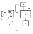
- FIG. 1 shows a schematic block diagram of a medical infusion pump 1, comprising a battery 2 as power source, a processor 3, a voltage supervisor 4, a memory 5 and a voltage converter 6.
- the battery 2 is connected to the voltage converter 6.
- the voltage converter 6 is a DC-DC step-up converter which converts the output voltage of the battery 2, which is typically between 1.2 volts and 1.5 volts, for example, to the operating voltage of the processor 3, which in the present exemplary embodiment is 3.08 volts.
- the output voltage or source voltage of the battery 2 is called Vbat
- the output voltage of the voltage converter 6, which is the input and supply voltage of the processor 3, is called VDD.
- the reset voltage level of the processor 3 is 2.6 volts. The reset voltage level is given by the processor specifications.
- the processor 3 controls an insulin pump (not shown) to deliver insulin from a reservoir (not shown) to a patient in a substantially continuous way as discussed above.
- the voltage supervisor 4 is connected to the output of the voltage converter 6 such that it can monitor the voltage VDD. If the voltage VDD drops to a response voltage level, for example 2.7 volts, the voltage supervisor 4 responds and generates an output signal indicative of this event.
- the output of the voltage supervisor 4 is connected to an input of the processor 3, preferably to an interrupt input port of the processor 3.
- An analogue input of the processor 3 is connected to the battery 2 such that the battery voltage Vbat can be determined.
- the processor 3 includes an A/D converter which converts the analogue voltage Vbat into a digital value which can be processed by the processor 3.
- the A/D converter can be external to the processor 3 as discussed above.
- the processor 3 starts sampling and logging the voltage Vbat and stores the values into memory 5 which is connected to the processor 3 either directly or via a link such as a data bus.
- the medical infusion pump 1 is configured to test, during normal operation, the battery 2 as described above and to provide a warning or alert, such as a message on a device display, an audible and/or a tactile alert if the battery 2 approaches the end of its lifetime.
- a warning or alert may be provided at one or multiple levels of the voltage Vbat for which the voltage VDD is above the response voltage level as discussed above. While the response voltage level is generally selected below the specified output voltage level of the voltage converter 6, a warning or alert is favourably given during normal operation at a voltage level for which the specified output voltage of the voltage converter 6 is still maintained, thus allowing replacement of battery 2 in due time and especially prior to the voltage supervisor (4) responding.
- the battery is automatically checked during normal operation in a time interval of typically some minutes. Those checks, however, require the processor to be in an operational mode and typically also involve coupling the battery to a test load. They are accordingly rather power consuming and should therefore not be carried out continuously or too frequently. Those checks do therefore typically not detect a sudden and unpredictable interruption of the power supply.
- the cause for the voltage VDD dropping to response voltage level can be one of several events.
- One event is that the battery 2 becomes weak.
- the internal resistance of the battery 2 causes a slight reduction of the voltage Vbat.
- An exemplary profile of voltage Vbat over time is depicted in Figure 3 .
- the voltage Vbat starts decreasing.
- the processor supply voltage VDD starts falling.
- the voltage VDD has fallen to a predetermined voltage level such that the voltage supervisor 4 responds and notifies the processor 3.
- the processor 3 starts logging the voltage Vbat in the memory 5.
- the voltage Vbat falls from a nominal voltage of 1.3 volts to a reduced voltage of 0.9 volts and remains about that level.
- the voltage converter 6 is able to stabilize the voltage VDD even from the reduced input voltage. As can be seen from Figure 3 , the voltage converter 6 can compensate the drop in the voltage Vbat. At the time T4, the voltage VDD rises above the predetermined voltage level of 2.7 volts again. At that time, the processor 3 stops logging Vbat. From the voltage Vbat being 0.9 volts at the time T4, it can be determined that the cause of the drop of the processor supply voltage VDD was within the battery 2, that is, the battery is of poor quality and has a high internal resistance.
- FIG. 2 shows the profiles of voltages Vbat and VDD for a second event in which the user of the infusion pump 1 removes the battery 2 during normal operation of the infusion pump.
- This kind of mishandling is known to occasionally occur if a user intends to replace the battery 2 but forgets to previously stop operation of the infusion pump by switching it into a different operational mode, for example a stop mode or maintenance mode, for replacing the battery.
- the voltage Vbat rapidly drops from the nominal value of 1.3 volts to a level of 0.5 volts.
- the 0.5 volts level results from an internal buffer capacitor (not shown) in the power supply path. In an unbuffered system, the voltage level would drop to zero.
- the voltage VDD starts decreasing.
- the voltage VDD has reached the response voltage level, 2.7 volts in the present example, such that the voltage supervisor 4 responds and notifies the processor 3.
- the processor 3 then starts logging the battery voltage Vbat in the memory 5. Since the voltage converter 6 is not able to stabilize its output voltage VDD, it falls to and below the reset voltage level.
- the logging data are stored in the memory 5 where they are maintained, independent of the drop and/or interruption of the voltage Vbat and VDD, respectively.
- a special mode such as a stop mode or a maintenance mode which should be selected for replacing the battery
- monitoring of voltage VDD may not be carried out in that mode.
- voltage supervisor 3 responds when battery 2 is removed.
- the voltage log may be cleared with the following power-up since it is not indicative of any mishandling, misuse or battery or device error.
- the processor 3 powers up again and a corresponding entry is stored in a device history.
- the voltage log may be permanently kept in the memory and stored, or characteristic data may now be extracted or computed from the log and may be permanently stored, while the voltage log itself is cleared.
- This time span can be determined as follows: When the processor and the pump 1 are powered up again, they may run through a self-testing and powering-up routine of several seconds.
- the program code of the power-up routine is typically part of the general firmware code that controls operation of the processor 3.
- a corresponding power-up entry is stored in the history memory of the device together with a timestamp. If the time between the beginning of the logging, or the last logged value before voltage VDD has dropped to the reset voltage level, and the power-up entry is considerably (i.e. in the range of half a second or more) longer than the time required for running through the power-up routine, the battery had been removed. Otherwise, the battery was disconnected only for a very short period, e.g., because of a dropping of the device.
- the power supply of the medical infusion pump 1 is interrupted only for a short period of time as shown in Figure 4 , for example if a contact spring which establishes the electrical contact with an electrode of the battery temporarily disconnects.
- This causes the voltage VDD to sharply drop at a time T1 to the response voltage level at time T5.
- the voltage VDD falls to the reset voltage level of the processor 3 as shown in Figure 4 , so that the processor 3 terminates operation and is powered up again when the voltage VDD rises to the reset voltage again at time T7.
- a corresponding power-up entry is stored in the history memory 5 of the device.
- the interruption of the power supply may be so short that the voltage VDD does drop to the response voltage level, causing the voltage supervisor 4 to respond, but not does not drop to the reset voltage of the processor 3.
- operation of the device 1 is not impaired, the corresponding event is accordingly a "nearly interruption".
- the logged voltage profile can be cleared and no permanent storing is required. This may be carried out by the device automatically after logging has stopped. As an alternative, the logged voltage profile can be permanently stored anyway for information purposes in this case.
- certain characteristic data such as the voltage Vbat at the beginning of the logging and when the voltage VDD reaches the reset voltage level, the time span between beginning and ending of the logging, and the time span until the next following power-up, may be stored additionally or alternatively to the actual voltage profile.
- a drop of the voltage Vbat, and therefore of the voltage VDD, can also occur if large currents are drawn from the battery 2 and the battery 2 is weak but still capable of powering the infusion pump under typical operational conditions. This might be the case, for example, if the pump is activated to infuse an amount of insulin, for example to infuse an on-demand insulin bolus, while the background light of a typically present display is switched on. However, the background light and the pump are often activated for several seconds and the voltage Vbat decreases slowly because of the drawn current, such that the time span between the beginning of the logging and the last logged value before voltage VDD has dropped to the reset voltage level, and the power-up entry is quite long, and the voltage Vbat additionally does not drop as deep as to zero or near zero. Therefore, power interruption caused by large power consumption in combination with a weak battery can also be retrospectively identified and is distinguishable from a device mishandling.
- FIG. 5 schematically illustrates, in combination with Figure 1 , essential steps that may be carried out in an exemplary embodiment.
- voltage supervisor 4 monitors voltage VDD and checks whether it has dropped to the response voltage level. If this is not the case, logging is continued. Step 102 is carried out continuously during normal operation as described above. If voltage VDD has dropped to the response voltage level, the voltage supervisor 3 notifies, in step 104, the processor 4, e.g., via an interrupt line and the processor starts a logging routine, including activating an A/D converter. The following steps are carried out under the general control of processor 4.
- step 106 a current value of voltage Vbat is logged, that is, A/D converted and stored in memory 5.
- an A/D converter may be operated continuously and may be checked in step 102 to detect if the voltage Vbat is to be logged.
- step 108 it is tested whether logging may be stopped because the voltage VDD will not drop to the reset level according to a method as described above. In this case, operation is continued with step 110.
- step 110 the logging routine is stopped.
- the voltage log may optionally be cleared and/or a "nearly interruption" history entry may be made. Operation subsequently proceeds with the monitoring step 102.
- step 106 If logging can not be stopped in step 108, operation continues with step 106 where a next value is logged. Logging continues until it is stopped according to the test in step 108 or the voltage VDD drops to the reset voltage level.
- a power-up routine is run through as described above, including a corresponding history entry.
- a special entry is favourably made in the history in addition or alternatively to the general power-up entry.
- processor 3 may now extract or compute those data and store them in the history, followed by clearing the power log.
Landscapes
- Health & Medical Sciences (AREA)
- General Physics & Mathematics (AREA)
- Physics & Mathematics (AREA)
- Engineering & Computer Science (AREA)
- Biomedical Technology (AREA)
- Veterinary Medicine (AREA)
- Hematology (AREA)
- Life Sciences & Earth Sciences (AREA)
- Animal Behavior & Ethology (AREA)
- General Health & Medical Sciences (AREA)
- Public Health (AREA)
- Heart & Thoracic Surgery (AREA)
- Anesthesiology (AREA)
- Vascular Medicine (AREA)
- Business, Economics & Management (AREA)
- Emergency Management (AREA)
- Power Engineering (AREA)
- Infusion, Injection, And Reservoir Apparatuses (AREA)
- External Artificial Organs (AREA)
Priority Applications (1)
| Application Number | Priority Date | Filing Date | Title |
|---|---|---|---|
| EP10008699.0A EP2295093B1 (de) | 2009-09-10 | 2010-08-20 | Medizinische Infusionspumpe mit Energiequellenspannungserfassung und Verfahren zur Erfassung einer Energiequellenspannung in einer medizinischen Infusionspumpe |
Applications Claiming Priority (2)
| Application Number | Priority Date | Filing Date | Title |
|---|---|---|---|
| EP20090169936 EP2295098B1 (de) | 2009-09-10 | 2009-09-10 | Medizinische Infusionspumpe und Verfahren zur Bestimmung der Ursache einer Stromunterbrechung in der Pumpe |
| EP10008699.0A EP2295093B1 (de) | 2009-09-10 | 2010-08-20 | Medizinische Infusionspumpe mit Energiequellenspannungserfassung und Verfahren zur Erfassung einer Energiequellenspannung in einer medizinischen Infusionspumpe |
Publications (3)
| Publication Number | Publication Date |
|---|---|
| EP2295093A2 true EP2295093A2 (de) | 2011-03-16 |
| EP2295093A3 EP2295093A3 (de) | 2011-08-03 |
| EP2295093B1 EP2295093B1 (de) | 2017-11-29 |
Family
ID=41791182
Family Applications (2)
| Application Number | Title | Priority Date | Filing Date |
|---|---|---|---|
| EP20090169936 Active EP2295098B1 (de) | 2009-09-10 | 2009-09-10 | Medizinische Infusionspumpe und Verfahren zur Bestimmung der Ursache einer Stromunterbrechung in der Pumpe |
| EP10008699.0A Active EP2295093B1 (de) | 2009-09-10 | 2010-08-20 | Medizinische Infusionspumpe mit Energiequellenspannungserfassung und Verfahren zur Erfassung einer Energiequellenspannung in einer medizinischen Infusionspumpe |
Family Applications Before (1)
| Application Number | Title | Priority Date | Filing Date |
|---|---|---|---|
| EP20090169936 Active EP2295098B1 (de) | 2009-09-10 | 2009-09-10 | Medizinische Infusionspumpe und Verfahren zur Bestimmung der Ursache einer Stromunterbrechung in der Pumpe |
Country Status (4)
| Country | Link |
|---|---|
| US (4) | US8262617B2 (de) |
| EP (2) | EP2295098B1 (de) |
| AT (1) | ATE530213T1 (de) |
| DK (1) | DK2295098T3 (de) |
Cited By (2)
| Publication number | Priority date | Publication date | Assignee | Title |
|---|---|---|---|---|
| US11554209B2 (en) | 2015-05-08 | 2023-01-17 | Triple Jump Israel Ltd. | Systems, apparatuses and methods for fluid infusion into a body |
| US11596733B2 (en) | 2017-06-15 | 2023-03-07 | Triple Jump Israel Ltd. | Patch pump systems and apparatus for managing diabetes, and methods thereof |
Families Citing this family (35)
| Publication number | Priority date | Publication date | Assignee | Title |
|---|---|---|---|---|
| JP5385155B2 (ja) | 2007-02-05 | 2014-01-08 | ボストン サイエンティフィック リミテッド | 血栓除去装置 |
| US20080228056A1 (en) | 2007-03-13 | 2008-09-18 | Michael Blomquist | Basal rate testing using frequent blood glucose input |
| US7751907B2 (en) | 2007-05-24 | 2010-07-06 | Smiths Medical Asd, Inc. | Expert system for insulin pump therapy |
| US8221345B2 (en) | 2007-05-30 | 2012-07-17 | Smiths Medical Asd, Inc. | Insulin pump based expert system |
| US20090177147A1 (en) | 2008-01-07 | 2009-07-09 | Michael Blomquist | Insulin pump with insulin therapy coaching |
| US9510854B2 (en) | 2008-10-13 | 2016-12-06 | Boston Scientific Scimed, Inc. | Thrombectomy catheter with control box having pressure/vacuum valve for synchronous aspiration and fluid irrigation |
| US9211377B2 (en) | 2009-07-30 | 2015-12-15 | Tandem Diabetes Care, Inc. | Infusion pump system with disposable cartridge having pressure venting and pressure feedback |
| DK2295098T3 (da) * | 2009-09-10 | 2012-02-20 | Hoffmann La Roche | Medicinsk infusionspumpe og fremgangsmåde til bestemmelse af årsagen til en energiafbrydelse i pumpen |
| US8882701B2 (en) | 2009-12-04 | 2014-11-11 | Smiths Medical Asd, Inc. | Advanced step therapy delivery for an ambulatory infusion pump and system |
| US8612055B2 (en) * | 2010-04-16 | 2013-12-17 | Medtronic, Inc. | System and method for delivering a therapeutic agent according to default infusion schedule |
| US9940440B2 (en) | 2011-04-28 | 2018-04-10 | Medtronic, Inc. | Detecting and responding to software and hardware anomalies in a fluid delivery system |
| US9180242B2 (en) | 2012-05-17 | 2015-11-10 | Tandem Diabetes Care, Inc. | Methods and devices for multiple fluid transfer |
| US9238100B2 (en) | 2012-06-07 | 2016-01-19 | Tandem Diabetes Care, Inc. | Device and method for training users of ambulatory medical devices |
| US8454557B1 (en) * | 2012-07-19 | 2013-06-04 | Asante Solutions, Inc. | Infusion pump system and method |
| DE102012018799A1 (de) | 2012-09-22 | 2014-03-27 | Dräger Safety AG & Co. KGaA | Versorgungsschaltung in einem Kommunikationssystem einer Kopfschutzbedeckung, Kopfschutzbedeckung mit einer solchen Versorgungsschaltung und Verfahren zum Betrieb einer solchen Versorgungsschaltung |
| RU2641517C2 (ru) * | 2012-09-24 | 2018-01-17 | Конинклейке Филипс Н.В. | Система молокоотсоса с приводом |
| US9173998B2 (en) | 2013-03-14 | 2015-11-03 | Tandem Diabetes Care, Inc. | System and method for detecting occlusions in an infusion pump |
| US9796347B2 (en) * | 2014-01-06 | 2017-10-24 | Union Pacific Railroad Company | Maintenance of a minimum voltage to equipment in rail vehicle |
| US9433427B2 (en) | 2014-04-08 | 2016-09-06 | Incuvate, Llc | Systems and methods for management of thrombosis |
| US9248221B2 (en) | 2014-04-08 | 2016-02-02 | Incuvate, Llc | Aspiration monitoring system and method |
| US9883877B2 (en) | 2014-05-19 | 2018-02-06 | Walk Vascular, Llc | Systems and methods for removal of blood and thrombotic material |
| US9669160B2 (en) | 2014-07-30 | 2017-06-06 | Tandem Diabetes Care, Inc. | Temporary suspension for closed-loop medicament therapy |
| WO2017040317A1 (en) | 2015-08-28 | 2017-03-09 | Thoratec Corporation | Blood pump controllers and methods of use for improved energy efficiency |
| US10702292B2 (en) | 2015-08-28 | 2020-07-07 | Incuvate, Llc | Aspiration monitoring system and method |
| US10561440B2 (en) | 2015-09-03 | 2020-02-18 | Vesatek, Llc | Systems and methods for manipulating medical devices |
| US20170100142A1 (en) | 2015-10-09 | 2017-04-13 | Incuvate, Llc | Systems and methods for management of thrombosis |
| US10226263B2 (en) | 2015-12-23 | 2019-03-12 | Incuvate, Llc | Aspiration monitoring system and method |
| US10569016B2 (en) | 2015-12-29 | 2020-02-25 | Tandem Diabetes Care, Inc. | System and method for switching between closed loop and open loop control of an ambulatory infusion pump |
| US10492805B2 (en) | 2016-04-06 | 2019-12-03 | Walk Vascular, Llc | Systems and methods for thrombolysis and delivery of an agent |
| US20170352246A1 (en) * | 2016-06-06 | 2017-12-07 | SITREP Marine Inc. | Equipment monitoring system and method of its use |
| US10180844B2 (en) * | 2017-01-20 | 2019-01-15 | Oracle International Corporation | Boot path and production path accessible storage system |
| CN111263655B (zh) * | 2017-10-27 | 2024-02-06 | 深圳迈瑞生物医疗电子股份有限公司 | 除颤仪及状态检测管理方法、状态检测管理系统、设备 |
| JP6787945B2 (ja) * | 2018-04-27 | 2020-11-18 | ファナック株式会社 | 機械状態監視装置 |
| US11678905B2 (en) | 2018-07-19 | 2023-06-20 | Walk Vascular, Llc | Systems and methods for removal of blood and thrombotic material |
| US11892520B2 (en) * | 2022-03-28 | 2024-02-06 | Changxin Memory Technologies, Inc. | Method and device for power supply mapping detection, electronic device, and medium |
Citations (2)
| Publication number | Priority date | Publication date | Assignee | Title |
|---|---|---|---|---|
| US5764034A (en) | 1996-04-10 | 1998-06-09 | Baxter International Inc. | Battery gauge for a battery operated infusion pump |
| US20070293914A1 (en) | 1999-07-27 | 2007-12-20 | Advanced Bionics Corporation | Patient programmer for implantable devices |
Family Cites Families (19)
| Publication number | Priority date | Publication date | Assignee | Title |
|---|---|---|---|---|
| US4707795A (en) * | 1983-03-14 | 1987-11-17 | Alber Engineering, Inc. | Battery testing and monitoring system |
| US5321392A (en) * | 1991-10-18 | 1994-06-14 | Baxter International Inc. | Infusion pump with battery back-up |
| DE19623788A1 (de) * | 1996-06-04 | 1997-12-11 | Biotronik Mess & Therapieg | Implantierbares Stimulationsgerät |
| US5847587A (en) * | 1997-01-07 | 1998-12-08 | Holtek Microelectronics Inc. | Means for instantaneously detecting abnormal voltage in a micro controller |
| DE69816032D1 (de) * | 1998-04-30 | 2003-08-07 | St Microelectronics Srl | Verfahren zur Sicherung von Daten im Falle unerwünschter Unterbrechnungen während ein Programmzyklus eines nichtflüchtigen Speichers, und ein nichtflüchtiger Speicher |
| US6494827B1 (en) * | 1998-10-29 | 2002-12-17 | Olympus Optical Co., Ltd. | Endoscope device and operation apparatus |
| US6733446B2 (en) * | 2000-01-21 | 2004-05-11 | Medtronic Minimed, Inc. | Ambulatory medical apparatus and method using a telemetry system with predefined reception listening periods |
| US7519909B2 (en) * | 2001-08-10 | 2009-04-14 | American Power Conversion Corporation | Uninterruptible power supply (UPS) devices monitoring system |
| WO2003036722A1 (fr) * | 2001-10-26 | 2003-05-01 | Fujitsu Limited | Circuit integre a semi-conducteur, dispositif electronique dans lequel ce circuit integre est incorpore et procede d'economie d'energie |
| JP4201629B2 (ja) * | 2003-03-26 | 2008-12-24 | 三洋電機株式会社 | 誤書込み防止回路および該誤書込み防止回路を含む半導体装置 |
| US8077889B2 (en) * | 2004-01-27 | 2011-12-13 | Phonak Ag | Method to log data in a hearing device as well as a hearing device |
| AU2006218360B2 (en) * | 2005-03-04 | 2011-08-04 | Philadelphia Scientific Llc | Device and method for monitoring life history and controlling maintenance of industrial batteries |
| US7737581B2 (en) * | 2005-08-16 | 2010-06-15 | Medtronic Minimed, Inc. | Method and apparatus for predicting end of battery life |
| US7941144B2 (en) * | 2006-05-19 | 2011-05-10 | Telefonaktiebolaget Lm Ericsson (Publ) | Access control in a mobile communication system |
| JP4265629B2 (ja) * | 2006-08-01 | 2009-05-20 | トヨタ自動車株式会社 | 二次電池の充放電制御装置およびそれを搭載したハイブリッド車両 |
| CN101425678B (zh) * | 2007-10-30 | 2011-11-23 | 比亚迪股份有限公司 | 电池保护方法和系统 |
| US7860672B2 (en) * | 2007-12-26 | 2010-12-28 | Elster Electricity, Llc | Method and apparatus for monitoring voltage in a meter network |
| US8331150B2 (en) * | 2008-01-03 | 2012-12-11 | Aplus Flash Technology, Inc. | Integrated SRAM and FLOTOX EEPROM memory device |
| DK2295098T3 (da) * | 2009-09-10 | 2012-02-20 | Hoffmann La Roche | Medicinsk infusionspumpe og fremgangsmåde til bestemmelse af årsagen til en energiafbrydelse i pumpen |
-
2009
- 2009-09-10 DK DK09169936T patent/DK2295098T3/da active
- 2009-09-10 EP EP20090169936 patent/EP2295098B1/de active Active
- 2009-09-10 AT AT09169936T patent/ATE530213T1/de not_active IP Right Cessation
-
2010
- 2010-08-20 EP EP10008699.0A patent/EP2295093B1/de active Active
- 2010-09-08 US US12/877,582 patent/US8262617B2/en active Active
-
2012
- 2012-08-09 US US13/570,696 patent/US8670836B2/en active Active
-
2014
- 2014-02-06 US US14/174,257 patent/US9316700B2/en active Active
-
2016
- 2016-03-04 US US15/060,916 patent/US10267865B2/en active Active
Patent Citations (2)
| Publication number | Priority date | Publication date | Assignee | Title |
|---|---|---|---|---|
| US5764034A (en) | 1996-04-10 | 1998-06-09 | Baxter International Inc. | Battery gauge for a battery operated infusion pump |
| US20070293914A1 (en) | 1999-07-27 | 2007-12-20 | Advanced Bionics Corporation | Patient programmer for implantable devices |
Cited By (2)
| Publication number | Priority date | Publication date | Assignee | Title |
|---|---|---|---|---|
| US11554209B2 (en) | 2015-05-08 | 2023-01-17 | Triple Jump Israel Ltd. | Systems, apparatuses and methods for fluid infusion into a body |
| US11596733B2 (en) | 2017-06-15 | 2023-03-07 | Triple Jump Israel Ltd. | Patch pump systems and apparatus for managing diabetes, and methods thereof |
Also Published As
| Publication number | Publication date |
|---|---|
| US8262617B2 (en) | 2012-09-11 |
| EP2295093B1 (de) | 2017-11-29 |
| US20140194848A1 (en) | 2014-07-10 |
| US20120302988A1 (en) | 2012-11-29 |
| US20160199570A1 (en) | 2016-07-14 |
| EP2295098B1 (de) | 2011-10-26 |
| US10267865B2 (en) | 2019-04-23 |
| US9316700B2 (en) | 2016-04-19 |
| US20110060281A1 (en) | 2011-03-10 |
| EP2295098A1 (de) | 2011-03-16 |
| EP2295093A3 (de) | 2011-08-03 |
| US8670836B2 (en) | 2014-03-11 |
| DK2295098T3 (da) | 2012-02-20 |
| ATE530213T1 (de) | 2011-11-15 |
Similar Documents
| Publication | Publication Date | Title |
|---|---|---|
| US10267865B2 (en) | Portable device with power monitoring to signal battery replacement prior to a voltage supervisor response | |
| US8970388B2 (en) | Battery life indication techniques for an electronic device | |
| US9755452B2 (en) | Power control techniques for an electronic device | |
| DK2605812T3 (en) | AMBULATORY INFUSION DEVICE WITH REPLACEABLE ENERGY STORAGE AND METHOD OF MONITORING ENERGY STORAGE | |
| DK2108393T3 (en) | Administration device with patient condition monitor | |
| DK2338546T3 (en) | Ambulatory infusion device with variable energy storage test and method for testing an energy storage | |
| EP2321755B1 (de) | Ambulante medizinische vorrichtung mit warnungsauslösungseinheit | |
| US11686774B2 (en) | Medical device with battery testing | |
| US8696617B2 (en) | Portable drug administration device and method for controlling a portable drug administration device | |
| US8970170B2 (en) | Ambulatory infusion device with variable energy storage testing and method for testing an energy storage |
Legal Events
| Date | Code | Title | Description |
|---|---|---|---|
| PUAI | Public reference made under article 153(3) epc to a published international application that has entered the european phase |
Free format text: ORIGINAL CODE: 0009012 |
|
| AK | Designated contracting states |
Kind code of ref document: A2 Designated state(s): AL AT BE BG CH CY CZ DE DK EE ES FI FR GB GR HR HU IE IS IT LI LT LU LV MC MK MT NL NO PL PT RO SE SI SK SM TR |
|
| AX | Request for extension of the european patent |
Extension state: BA ME RS |
|
| PUAL | Search report despatched |
Free format text: ORIGINAL CODE: 0009013 |
|
| AK | Designated contracting states |
Kind code of ref document: A3 Designated state(s): AL AT BE BG CH CY CZ DE DK EE ES FI FR GB GR HR HU IE IS IT LI LT LU LV MC MK MT NL NO PL PT RO SE SI SK SM TR |
|
| AX | Request for extension of the european patent |
Extension state: BA ME RS |
|
| RIC1 | Information provided on ipc code assigned before grant |
Ipc: A61M 5/142 20060101ALI20110629BHEP Ipc: A61M 5/172 20060101AFI20110629BHEP |
|
| 17P | Request for examination filed |
Effective date: 20111110 |
|
| RAP1 | Party data changed (applicant data changed or rights of an application transferred) |
Owner name: F.HOFFMANN-LA ROCHE AG Owner name: ROCHE DIABETES CARE GMBH |
|
| 17Q | First examination report despatched |
Effective date: 20160811 |
|
| STAA | Information on the status of an ep patent application or granted ep patent |
Free format text: STATUS: EXAMINATION IS IN PROGRESS |
|
| GRAP | Despatch of communication of intention to grant a patent |
Free format text: ORIGINAL CODE: EPIDOSNIGR1 |
|
| STAA | Information on the status of an ep patent application or granted ep patent |
Free format text: STATUS: GRANT OF PATENT IS INTENDED |
|
| INTG | Intention to grant announced |
Effective date: 20170619 |
|
| RIC1 | Information provided on ipc code assigned before grant |
Ipc: G01R 31/36 20060101ALI20170602BHEP Ipc: A61M 5/142 20060101AFI20170602BHEP |
|
| GRAS | Grant fee paid |
Free format text: ORIGINAL CODE: EPIDOSNIGR3 |
|
| GRAA | (expected) grant |
Free format text: ORIGINAL CODE: 0009210 |
|
| STAA | Information on the status of an ep patent application or granted ep patent |
Free format text: STATUS: THE PATENT HAS BEEN GRANTED |
|
| AK | Designated contracting states |
Kind code of ref document: B1 Designated state(s): AL AT BE BG CH CY CZ DE DK EE ES FI FR GB GR HR HU IE IS IT LI LT LU LV MC MK MT NL NO PL PT RO SE SI SK SM TR |
|
| REG | Reference to a national code |
Ref country code: CH Ref legal event code: EP |
|
| REG | Reference to a national code |
Ref country code: AT Ref legal event code: REF Ref document number: 949817 Country of ref document: AT Kind code of ref document: T Effective date: 20171215 |
|
| REG | Reference to a national code |
Ref country code: IE Ref legal event code: FG4D |
|
| REG | Reference to a national code |
Ref country code: DE Ref legal event code: R096 Ref document number: 602010046983 Country of ref document: DE |
|
| REG | Reference to a national code |
Ref country code: NL Ref legal event code: MP Effective date: 20171129 |
|
| REG | Reference to a national code |
Ref country code: LT Ref legal event code: MG4D |
|
| REG | Reference to a national code |
Ref country code: AT Ref legal event code: MK05 Ref document number: 949817 Country of ref document: AT Kind code of ref document: T Effective date: 20171129 |
|
| PG25 | Lapsed in a contracting state [announced via postgrant information from national office to epo] |
Ref country code: ES Free format text: LAPSE BECAUSE OF FAILURE TO SUBMIT A TRANSLATION OF THE DESCRIPTION OR TO PAY THE FEE WITHIN THE PRESCRIBED TIME-LIMIT Effective date: 20171129 Ref country code: FI Free format text: LAPSE BECAUSE OF FAILURE TO SUBMIT A TRANSLATION OF THE DESCRIPTION OR TO PAY THE FEE WITHIN THE PRESCRIBED TIME-LIMIT Effective date: 20171129 Ref country code: SE Free format text: LAPSE BECAUSE OF FAILURE TO SUBMIT A TRANSLATION OF THE DESCRIPTION OR TO PAY THE FEE WITHIN THE PRESCRIBED TIME-LIMIT Effective date: 20171129 Ref country code: LT Free format text: LAPSE BECAUSE OF FAILURE TO SUBMIT A TRANSLATION OF THE DESCRIPTION OR TO PAY THE FEE WITHIN THE PRESCRIBED TIME-LIMIT Effective date: 20171129 Ref country code: NO Free format text: LAPSE BECAUSE OF FAILURE TO SUBMIT A TRANSLATION OF THE DESCRIPTION OR TO PAY THE FEE WITHIN THE PRESCRIBED TIME-LIMIT Effective date: 20180228 |
|
| PG25 | Lapsed in a contracting state [announced via postgrant information from national office to epo] |
Ref country code: GR Free format text: LAPSE BECAUSE OF FAILURE TO SUBMIT A TRANSLATION OF THE DESCRIPTION OR TO PAY THE FEE WITHIN THE PRESCRIBED TIME-LIMIT Effective date: 20180301 Ref country code: LV Free format text: LAPSE BECAUSE OF FAILURE TO SUBMIT A TRANSLATION OF THE DESCRIPTION OR TO PAY THE FEE WITHIN THE PRESCRIBED TIME-LIMIT Effective date: 20171129 Ref country code: BG Free format text: LAPSE BECAUSE OF FAILURE TO SUBMIT A TRANSLATION OF THE DESCRIPTION OR TO PAY THE FEE WITHIN THE PRESCRIBED TIME-LIMIT Effective date: 20180228 Ref country code: AT Free format text: LAPSE BECAUSE OF FAILURE TO SUBMIT A TRANSLATION OF THE DESCRIPTION OR TO PAY THE FEE WITHIN THE PRESCRIBED TIME-LIMIT Effective date: 20171129 Ref country code: HR Free format text: LAPSE BECAUSE OF FAILURE TO SUBMIT A TRANSLATION OF THE DESCRIPTION OR TO PAY THE FEE WITHIN THE PRESCRIBED TIME-LIMIT Effective date: 20171129 |
|
| PG25 | Lapsed in a contracting state [announced via postgrant information from national office to epo] |
Ref country code: NL Free format text: LAPSE BECAUSE OF FAILURE TO SUBMIT A TRANSLATION OF THE DESCRIPTION OR TO PAY THE FEE WITHIN THE PRESCRIBED TIME-LIMIT Effective date: 20171129 |
|
| PG25 | Lapsed in a contracting state [announced via postgrant information from national office to epo] |
Ref country code: SK Free format text: LAPSE BECAUSE OF FAILURE TO SUBMIT A TRANSLATION OF THE DESCRIPTION OR TO PAY THE FEE WITHIN THE PRESCRIBED TIME-LIMIT Effective date: 20171129 Ref country code: EE Free format text: LAPSE BECAUSE OF FAILURE TO SUBMIT A TRANSLATION OF THE DESCRIPTION OR TO PAY THE FEE WITHIN THE PRESCRIBED TIME-LIMIT Effective date: 20171129 Ref country code: CY Free format text: LAPSE BECAUSE OF FAILURE TO SUBMIT A TRANSLATION OF THE DESCRIPTION OR TO PAY THE FEE WITHIN THE PRESCRIBED TIME-LIMIT Effective date: 20171129 Ref country code: DK Free format text: LAPSE BECAUSE OF FAILURE TO SUBMIT A TRANSLATION OF THE DESCRIPTION OR TO PAY THE FEE WITHIN THE PRESCRIBED TIME-LIMIT Effective date: 20171129 Ref country code: CZ Free format text: LAPSE BECAUSE OF FAILURE TO SUBMIT A TRANSLATION OF THE DESCRIPTION OR TO PAY THE FEE WITHIN THE PRESCRIBED TIME-LIMIT Effective date: 20171129 |
|
| REG | Reference to a national code |
Ref country code: DE Ref legal event code: R097 Ref document number: 602010046983 Country of ref document: DE |
|
| PG25 | Lapsed in a contracting state [announced via postgrant information from national office to epo] |
Ref country code: SM Free format text: LAPSE BECAUSE OF FAILURE TO SUBMIT A TRANSLATION OF THE DESCRIPTION OR TO PAY THE FEE WITHIN THE PRESCRIBED TIME-LIMIT Effective date: 20171129 Ref country code: PL Free format text: LAPSE BECAUSE OF FAILURE TO SUBMIT A TRANSLATION OF THE DESCRIPTION OR TO PAY THE FEE WITHIN THE PRESCRIBED TIME-LIMIT Effective date: 20171129 Ref country code: IT Free format text: LAPSE BECAUSE OF FAILURE TO SUBMIT A TRANSLATION OF THE DESCRIPTION OR TO PAY THE FEE WITHIN THE PRESCRIBED TIME-LIMIT Effective date: 20171129 Ref country code: RO Free format text: LAPSE BECAUSE OF FAILURE TO SUBMIT A TRANSLATION OF THE DESCRIPTION OR TO PAY THE FEE WITHIN THE PRESCRIBED TIME-LIMIT Effective date: 20171129 |
|
| PLBE | No opposition filed within time limit |
Free format text: ORIGINAL CODE: 0009261 |
|
| STAA | Information on the status of an ep patent application or granted ep patent |
Free format text: STATUS: NO OPPOSITION FILED WITHIN TIME LIMIT |
|
| 26N | No opposition filed |
Effective date: 20180830 |
|
| PG25 | Lapsed in a contracting state [announced via postgrant information from national office to epo] |
Ref country code: SI Free format text: LAPSE BECAUSE OF FAILURE TO SUBMIT A TRANSLATION OF THE DESCRIPTION OR TO PAY THE FEE WITHIN THE PRESCRIBED TIME-LIMIT Effective date: 20171129 |
|
| PG25 | Lapsed in a contracting state [announced via postgrant information from national office to epo] |
Ref country code: MC Free format text: LAPSE BECAUSE OF FAILURE TO SUBMIT A TRANSLATION OF THE DESCRIPTION OR TO PAY THE FEE WITHIN THE PRESCRIBED TIME-LIMIT Effective date: 20171129 |
|
| REG | Reference to a national code |
Ref country code: CH Ref legal event code: PL |
|
| GBPC | Gb: european patent ceased through non-payment of renewal fee |
Effective date: 20180820 |
|
| PG25 | Lapsed in a contracting state [announced via postgrant information from national office to epo] |
Ref country code: LI Free format text: LAPSE BECAUSE OF NON-PAYMENT OF DUE FEES Effective date: 20180831 Ref country code: LU Free format text: LAPSE BECAUSE OF NON-PAYMENT OF DUE FEES Effective date: 20180820 Ref country code: CH Free format text: LAPSE BECAUSE OF NON-PAYMENT OF DUE FEES Effective date: 20180831 |
|
| REG | Reference to a national code |
Ref country code: BE Ref legal event code: MM Effective date: 20180831 |
|
| REG | Reference to a national code |
Ref country code: IE Ref legal event code: MM4A |
|
| PG25 | Lapsed in a contracting state [announced via postgrant information from national office to epo] |
Ref country code: IE Free format text: LAPSE BECAUSE OF NON-PAYMENT OF DUE FEES Effective date: 20180820 |
|
| PG25 | Lapsed in a contracting state [announced via postgrant information from national office to epo] |
Ref country code: BE Free format text: LAPSE BECAUSE OF NON-PAYMENT OF DUE FEES Effective date: 20180831 Ref country code: FR Free format text: LAPSE BECAUSE OF NON-PAYMENT OF DUE FEES Effective date: 20180831 |
|
| PG25 | Lapsed in a contracting state [announced via postgrant information from national office to epo] |
Ref country code: GB Free format text: LAPSE BECAUSE OF NON-PAYMENT OF DUE FEES Effective date: 20180820 |
|
| PG25 | Lapsed in a contracting state [announced via postgrant information from national office to epo] |
Ref country code: MT Free format text: LAPSE BECAUSE OF NON-PAYMENT OF DUE FEES Effective date: 20180820 |
|
| PG25 | Lapsed in a contracting state [announced via postgrant information from national office to epo] |
Ref country code: TR Free format text: LAPSE BECAUSE OF FAILURE TO SUBMIT A TRANSLATION OF THE DESCRIPTION OR TO PAY THE FEE WITHIN THE PRESCRIBED TIME-LIMIT Effective date: 20171129 |
|
| PG25 | Lapsed in a contracting state [announced via postgrant information from national office to epo] |
Ref country code: HU Free format text: LAPSE BECAUSE OF FAILURE TO SUBMIT A TRANSLATION OF THE DESCRIPTION OR TO PAY THE FEE WITHIN THE PRESCRIBED TIME-LIMIT; INVALID AB INITIO Effective date: 20100820 Ref country code: PT Free format text: LAPSE BECAUSE OF FAILURE TO SUBMIT A TRANSLATION OF THE DESCRIPTION OR TO PAY THE FEE WITHIN THE PRESCRIBED TIME-LIMIT Effective date: 20171129 |
|
| PG25 | Lapsed in a contracting state [announced via postgrant information from national office to epo] |
Ref country code: MK Free format text: LAPSE BECAUSE OF NON-PAYMENT OF DUE FEES Effective date: 20171129 |
|
| PG25 | Lapsed in a contracting state [announced via postgrant information from national office to epo] |
Ref country code: AL Free format text: LAPSE BECAUSE OF FAILURE TO SUBMIT A TRANSLATION OF THE DESCRIPTION OR TO PAY THE FEE WITHIN THE PRESCRIBED TIME-LIMIT Effective date: 20171129 Ref country code: IS Free format text: LAPSE BECAUSE OF FAILURE TO SUBMIT A TRANSLATION OF THE DESCRIPTION OR TO PAY THE FEE WITHIN THE PRESCRIBED TIME-LIMIT Effective date: 20180329 |
|
| PGFP | Annual fee paid to national office [announced via postgrant information from national office to epo] |
Ref country code: DE Payment date: 20230720 Year of fee payment: 14 |