EP2295001A2 - Einwegbehälter zum Darbieten von Verbandstoffen sowie wegwerfbares OP-Spendersystem - Google Patents
Einwegbehälter zum Darbieten von Verbandstoffen sowie wegwerfbares OP-Spendersystem Download PDFInfo
- Publication number
- EP2295001A2 EP2295001A2 EP10009317A EP10009317A EP2295001A2 EP 2295001 A2 EP2295001 A2 EP 2295001A2 EP 10009317 A EP10009317 A EP 10009317A EP 10009317 A EP10009317 A EP 10009317A EP 2295001 A2 EP2295001 A2 EP 2295001A2
- Authority
- EP
- European Patent Office
- Prior art keywords
- disposable container
- disposable
- lid
- fixing means
- instrument table
- Prior art date
- Legal status (The legal status is an assumption and is not a legal conclusion. Google has not performed a legal analysis and makes no representation as to the accuracy of the status listed.)
- Granted
Links
Images


Classifications
-
- A—HUMAN NECESSITIES
- A61—MEDICAL OR VETERINARY SCIENCE; HYGIENE
- A61B—DIAGNOSIS; SURGERY; IDENTIFICATION
- A61B50/00—Containers, covers, furniture or holders specially adapted for surgical or diagnostic appliances or instruments, e.g. sterile covers
- A61B50/30—Containers specially adapted for packaging, protecting, dispensing, collecting or disposing of surgical or diagnostic appliances or instruments
-
- A—HUMAN NECESSITIES
- A61—MEDICAL OR VETERINARY SCIENCE; HYGIENE
- A61B—DIAGNOSIS; SURGERY; IDENTIFICATION
- A61B50/00—Containers, covers, furniture or holders specially adapted for surgical or diagnostic appliances or instruments, e.g. sterile covers
- A61B50/10—Furniture specially adapted for surgical or diagnostic appliances or instruments
- A61B50/15—Mayo stands; Tables
-
- A—HUMAN NECESSITIES
- A61—MEDICAL OR VETERINARY SCIENCE; HYGIENE
- A61B—DIAGNOSIS; SURGERY; IDENTIFICATION
- A61B50/00—Containers, covers, furniture or holders specially adapted for surgical or diagnostic appliances or instruments, e.g. sterile covers
- A61B2050/002—Containers, covers, furniture or holders specially adapted for surgical or diagnostic appliances or instruments, e.g. sterile covers having adhesive means, e.g. an adhesive strip
-
- A—HUMAN NECESSITIES
- A61—MEDICAL OR VETERINARY SCIENCE; HYGIENE
- A61B—DIAGNOSIS; SURGERY; IDENTIFICATION
- A61B50/00—Containers, covers, furniture or holders specially adapted for surgical or diagnostic appliances or instruments, e.g. sterile covers
- A61B2050/005—Containers, covers, furniture or holders specially adapted for surgical or diagnostic appliances or instruments, e.g. sterile covers with a lid or cover
- A61B2050/0051—Containers, covers, furniture or holders specially adapted for surgical or diagnostic appliances or instruments, e.g. sterile covers with a lid or cover closable by rotation
- A61B2050/0056—Containers, covers, furniture or holders specially adapted for surgical or diagnostic appliances or instruments, e.g. sterile covers with a lid or cover closable by rotation about a lateral axis in the lid plane
-
- A—HUMAN NECESSITIES
- A61—MEDICAL OR VETERINARY SCIENCE; HYGIENE
- A61B—DIAGNOSIS; SURGERY; IDENTIFICATION
- A61B50/00—Containers, covers, furniture or holders specially adapted for surgical or diagnostic appliances or instruments, e.g. sterile covers
- A61B50/30—Containers specially adapted for packaging, protecting, dispensing, collecting or disposing of surgical or diagnostic appliances or instruments
- A61B50/31—Carrying cases or bags, e.g. doctors' bags
- A61B2050/311—Cases
Definitions
- the invention relates to a disposable container for presenting dressings in the operating room with a bottom surface and at least one side surface, which defines an interior together with the bottom surface, wherein at least one side surface is connected to a lower side edge with the bottom surface and optionally a lid, the at least a side surface is articulated openable at an upper side edge.
- a disadvantage of the previous surgical containers is that the containers must be individually assembled in the hospital, packaged and sterilized and the sterilization process must be monitored and validated, as long as it is about such attachable reusable metal container.
- a disposable container for the presentation of dressings in the operating room with the features of claim 1.
- the object is achieved by a disposable surgical dispensing system comprising a disposable container according to one of claims 1 to 6, wherein in the interior of the disposable container manufacturer sterile absorbent dressings are presented.
- At least one area of one of the at least one side face and / or the lid is designed as a fixing agent zone with a fixing means, via which the disposable container can be fixed to a vertical and / or horizontal surface, in particular an instrument table.
- the disposable container By providing a fixing agent zone with a fixing agent in the region of one of the side surfaces of the disposable container and / or the lid, the disposable container can be hinged to a horizontal and / or vertical surface in such a way that it also enlarges the available surface, in particular the instrument table in this respect contributes to the fact that no space on the instrument table is required for the installation of the disposable container.
- the fact that a section of at least one of the at least one side surfaces in a fixing agent zone has a fixing means has the advantage that the side surfaces of the disposable container can be fixed on a vertical surface, in particular on a vertical surface of the instrument table via the fixing means.
- an instrument table for an operating room in this case has a horizontal upward surface with four side surfaces, so that a determination of the disposable container can be made on one of the side surfaces of the instrument table by means of the fixer in the Fixierstoffzone.
- the fixing means may also be provided in such a way that it extends over the at least one side surface of the One-way container provided Fixierstoffzone also extends, and thus advantageously folded in the direction of a horizontal surface, in particular on a horizontal surface of a instrument table and can be mounted on this horizontal surface.
- a tightly connected to the container lid is hinged to this, that the lower or inner or upper or outer side of the lid, so directed to the interior with the lid closed side or the thereof opposite side, are provided with a Fixierstoffzone.
- both sides of the cover may have a Fixierstoffzone, in which case either the lid can be opened so far that it rests with its outer side, ie the top, against the side wall of the container and then with the arranged on the inside fixing also on the vertical surface of the instrument table can be attached.
- the lid can also be pivoted by only 180 ° from the closed position to an open position and then be connected via the fixing means of Fixierstoffzone on the outside of the lid with the horizontal surface of the instrument table.
- the side surface of the disposable container can be supported against the vertical side surface of the instrument table, whereby a comparatively stable attachment can take place.
- the fixing means may also be provided such that it extends beyond the fixing means zone provided on the underside and / or outside of the cover, and thus advantageously folded in the direction of a horizontal surface, in particular on a horizontal surface of an instrument table, and on this horizontal surface can be fixed.
- the disposable container may optionally be formed with or without lid. If a disposable container is designed without a lid, it can be provided, for example, that the entire disposable container, in particular after filling, preferably with absorbent bandages, by the manufacturer, in a disposable cloth or a crepe paper or other disposable cover is taken and / or in a further outer packaging in which it is then preferably sterilized, is packed.
- the lid for the disposable container can be designed in alternative embodiments.
- the lid may be permanently connected to the disposable container.
- the lid is hinged to the disposable container via a hinge, preferably via an edge connecting the one side surface of the disposable container and the lid.
- the lid may also be provided as a removable lid on the disposable container, particularly in the form of a foil which closes the disposable container and is releasably secured to the upper side edges of the disposable container sidewalls, such as by adhesive or by means of a weld.
- a detachable lid can also be provided by the fact that the lid, in addition to its actual lid surface, also has corresponding side surfaces connected thereto, which cover the side surfaces of the disposable container with little play and thus provide a closable disposable container.
- the sealed disposable containers are introduced after filling, preferably with absorbent dressings, and sealing by the manufacturer in a further outer packaging as sterile packaging and sterilized therein.
- the disposable container is filled in such a way that simple counting of the products, in particular of the absorbent bandages, is possible. This can be done, for example, by appropriate positioning of the products, eg. B. with the folded edges up in the direction of the opening of the disposable container or lid, can be achieved.
- the surgical staff is offered a good overview of the offered absorption materials.
- the material of the disposable container may in particular be a solid paperboard material, in particular having a weight per unit area of 250 to 800 g / m 2 , preferably 350 to 600 g / m 2 .
- a use of corrugated board is possible.
- Under corrugated board is a multi-layer composite of paper and / or cardboard, from at least one level position and an S-shaped thereto, just a corrugated layer to understand. A flat layer can connect to the S-shaped layer. Corrugated boards with additional layers are conceivable.
- the disposable containers may be formed as folding boxes.
- individual edges of the disposable container, in particular the folding boxes can be reinforced to bulge out by the weight of the to prevent absorbent products, but also during sterilization of the products and disposable containers.
- the disposable container according to the invention has at least one side surface.
- a side surface is here any, a side wall of the disposable container forming surface understood. In the case of a continuous, self-contained and without interrupted by an edge sidewall, there is only one side surface.
- the disposable container has three side surfaces; So there are three edges in the side wall.
- the disposable container has four side surfaces, i. the side wall of the disposable container has correspondingly four edges.
- the disposable containers may be cuboid disposable containers in which the four, in particular straight, side surfaces have, in particular, two larger longitudinal surfaces spaced in parallel and two smaller longitudinal surfaces spaced in parallel.
- the size, in particular the length of the larger longitudinal surfaces can be determined by the dimensions of the instrument table, in particular the length of a side surface of the instrument table.
- the width and thus the length of the shorter side surfaces and the height of the side surfaces can be determined by the folded dimensions of the contents.
- the shorter side surface of the disposable container has a width and / or a height of not greater than 25 cm, preferably not greater than 20 cm and in particular preferably not greater than 15 cm.
- the width and / or height of the in particular shorter side surfaces should be at least 5 cm, more particularly at least 6 cm, more particularly at least 7 cm.
- the length of the longer side surfaces is preferably at least 20 cm, in particular at least 25 cm, more particularly at least 30 cm, more particularly at least 35 cm.
- the length of the longer side surfaces is at most 70 cm, in particular at most 65 cm, more particularly at most 60 cm.
- the disposable container has the dimensions length x width x height of 50 to 55 cm x 7 to 12 cm x 9 to 10 cm.
- the dimensions can be adjusted so that an optimal volume utilization during logistics and the storage process is guaranteed.
- a cuboid disposable container with four, in particular straight side surfaces is provided.
- the disposable container has a straight side surface, on which then preferably also the Fixierstoffzone is attached, and the remaining disposable container has a rounded side surface which is connected via two edges with the straight side surface.
- the fixing means is located on one of the side surfaces, preferably on a straight side surface, which is formed without curves, or in a region of a side surface, which is formed without bending.
- the fixing agent can also extend beyond the fixing agent zone and in particular the side surface and / or the cover.
- the fixation of the disposable container on the vertical and / or horizontal surface can then take place in the region of the fixing agent zone and / or in protruding areas of the fixing agent, which interact with surfaces, for example, of the instrument table.
- Fixing agent zone is to be understood as meaning at least the region in which the respective fixing means is arranged undetachably on the side surface of the disposable container and / or on the underside and / or outside of the lid.
- the fixing means fastened in the fixing agent zone can advantageously already be formed in this region of the fixing agent zone in its use for fixing / adhesion to a vertical and / or horizontal surface.
- the fixer central zone may not be provided for the fixation, but only the free overhang, that is to say the projecting region.
- both the region which is connected to the fixing agent zone and the region protruding therefrom can serve for fixing to a vertical and / or horizontal surface.
- the fixing means has a free overhang with such an extent, so that the fixing means extends beyond the upper edge of the side surface of the disposable container and / or beyond the free edge of the lid.
- the fixer zone may be attached to a side surface in the region of an upper side edge of a side surface of the disposable container.
- Fixierstoffzone on a side surface of the disposable container
- Fixierffenzone can be mounted on the inside and / or outside of the lid and so a fixation, as already described above, allow.
- the fixing agent zone starting from the side edge of the side surface connected to the cover, is arranged more in the direction of the free side edge of the cover.
- the width or height of the Fixierstoffzone, in particular a arranged on the side surface of the disposable container Fixierstoffzone is preferably adapted to the height of the side surface of an instrument panel or the vertical surface.
- the fixing agent zone extends substantially over the entire length of Side surface of the disposable container and / or over the entire length of the lid.
- spaced-apart fixing agent zones can also be provided.
- a plurality, ie at least two fixing agent zones can be provided, which are spaced apart from one another by fixing-area-free regions.
- each of the Fixierstoffzonen within the side surface and / or within the lid are arranged in a line spaced from each other.
- fixing means can be arranged both in the region of the cover and in the region of a side surface of the disposable container.
- the application of the individual fixing means can thus be adapted to the existing vertical and / or horizontal surfaces, in particular that of an instrument table.
- Adhesive fixing agents such as an adhesive application, in particular an adhesive adhesive or a single-sided or double-sided adhesive material, such as, for example, a double-sided adhesive film, which on one side in the region of the fixing agent zone on the disposable container on the side surface and / or on the lid and the other side of which may be unseeded by a release paper or release paper which is then removed prior to application and attachment to a horizontal or vertical surface so as to release an adhesive side.
- nonwoven materials may be used as carrier materials, in particular for one-sided adhesive materials, thus with an adhesive applied to them in particular on one side.
- This is particularly advantageous in the case of instrument tables, which are covered with a particular nonwoven material comprising disposable surgical cover, because so that the covered by the fixing of the fixing surfaces of disposable surgical cover further having a top with nonwoven material, in particular an absorbent nonwoven material.
- hook and / or eye-locking means may also be provided, in particular hook-fastening materials which may be adhesively connectable, for example, to a cover which is used to cover an instrument table and which preferably comprises non-woven material.
- Hook / eyelet adhesives are also referred to as hook / loop elements or as Velcro hook / Velcro elements.
- the fixing agent is to be chosen so that it can be fixed to the corresponding surface, in particular with a surface of surgical disposable covers, in particular with a textile surface of surgical disposable covers, which are preferably used for the instrument table, and on the Duration of an operation remains fixed.
- fixing means on the side surface of the disposable container and the cover different fixing means, in particular a combination of adhesive fixing means and of eyelet and / or hook-and-loop fasteners are used.
- the disposable container after the operation is not removed again from a cover or a cover of the instrument table, but can be disposed of with it.
- the disposable container is used after removal of all content materials for receiving used materials, which can then be disposed of together with the disposable container.
- the invention relates to a disposable surgical dispenser system, where the abbreviation OP always operation is to be understood.
- This disposable surgical dispensing system comprises a disposable container of the type described above, wherein in the interior manufacturer sterile, absorbent dressing materials are presented.
- These disposable surgical dispenser systems are advantageously, in particular in a further outer packaging, sterile packed. Sterilization is in particular a steam sterilization in question.
- the invention relates to a sterile disposable surgical dispensing system.
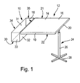
- FIG. 1 shows an instrument table, which is provided with the reference numeral 12, wherein the instrument table of a table top 14 with a horizontal upward surface 16 and four side surfaces 18, 19, 20 and 21 and a bottom 22 is formed.
- the instrument table 12 also has a foot 24 consisting of a leg 26 and a cross-shaped tripod 28th
- a disposable container 10 for presenting dressings in an operating room is shown with a bottom surface 30 and at least one side surface 32, wherein in the cuboid disposable container shown here four side surfaces, namely, 32, 33, 34 and 35, are provided, which define an interior 31 together with the bottom surface 30, wherein in the interior dressing materials manufacturer presented and presented can be presented.
- the side surfaces 32 to 35 are connected to the bottom surface 30, each having a lower side edge.
- a lid may be provided which, as in the FIG. 2 shown firmly connected to the disposable container 10.
- a completely removable lid is providable.
- FIG. 2 shows now in three views the disposable container 10, wherein in the illustration a) of the disposable container with closed lid 36 can be seen.
- the cover 36 is in particular articulated on an upper side edge, here the side surface 32, and can be pivoted from the closed position shown into an open position.
- the lid 36 is then shown in different open positions.
- the lid has an underside or inner side 41 and an upper side or outer side 37, which corresponds to the side directed toward the interior and the side remote therefrom when the lid is closed.
- FIG. 3 shows a plurality of disposable containers, wherein the representations with a) to 1) are designated.
- fixing 40 For attachment of the disposable container 10 on the instrument table 12 fixing 40 are provided, which are mounted in the region of a Fixierffenzone 42 on the disposable container 10.
- the fixing means 40 may be located exclusively in the fixer zone or extend beyond the fixer zone 42.
- an adhesive application or adhesive a double-sided or single-sided adhesive tape which, in the case of a single-sided adhesive tape, may for example be adhesively attached to the disposable container 10 via an additional adhesive in the region of the fixing agent zone 42.
- Illustration a) shows a first design, as well as in FIG. 1 Is used, wherein in the region of the upper side edge of the side surface 32, a Fixierffenzone 42 is provided which extends in the cuboid disposable container 10 substantially over the entire length of the side surface 32 and be adjusted in height to the height of the side surface 18 of the instrument table 12 can. If the instrument table 12 is covered with a covering, for example, of a nonwoven fabric, however, the fixing agent zone 42 can also have a greater extent in height and can also be anchored in this area with the cover of the instrument table 12.
- fixing means 40 here is a double-sided adhesive tape is provided, which is attached with its one side to the side surface 32 of the disposable container 10 and the other side is first covered with a release paper or release paper before use, to avoid undesirable adhesion before use.
- the release paper may be removed beforehand and the second adhesive side of the fixative 40 exposed.
- Representation b) shows a disposable container 10 with two fixing agent zones 42 'and 42 ", which are also arranged on the side surface 32 in the region of the upper side edge, in each case adjacent to the side surfaces 35 and 33 of the disposable container two fixing agent zones 42 'and 42 ", a fixing agent-free area is provided.
- Representation c) shows a disposable container 10 with a Fixierffenzone 42, which corresponds to the representation of a).
- the fixing means 40 is not only mounted in the area of the fixing agent zone 42, but also extends beyond the upper side edge of the side 32. This offers the advantage that in addition to an attachment to the side surface 18 of the instrument table, the fixing can still be folded and can be mounted on the horizontal surface 16 of the table. As a result, an even safer attachment is achieved.
- Representation d) shows an analogous design to representation c), but here with two fixing agent zones 42 'and 42 "analogous to representation b).
- Representation e) shows a configuration in which the fixing agent zone 42 in the region of the lid 36, which is shown half open, is mounted, on the outside 37 of the lid.
- the Fixierstoffzone 42 extends over a substantial part of the length of the lid and is arranged starting from the side edge with the side surface 32 rather in the direction of the free side edge 39 of the lid.
- Representation f) shows an attachment of a fixing means 40, which in turn is in turn divided into two fixing agent zones 42, but is also arranged on the outer side 37 of the lid 36.
- illustration g) is also an arrangement of the fixing means 40 in the region of the lid, in this case provided in the region of the free side edge 39 of the lid, wherein the fixing means 40 extends in part in the region of the Fixierstoffzone 42, but partly outside of this beyond the edge 39 addition.
- Representation h) again shows an analogous design to the representation g), wherein here two fixing means 40 are provided at a distance from one another.
- Representation i) shows a design according to representation g), in which case, however, the fixing means 40, which in turn is defined by the free edge 39 of the lid and the Fixierstoffzone 42 is provided in the region of the free edge 39 of the lid inner side 41.
- Representation j) again shows an analogous design, but here with two fixing means 40, which are spaced from each other, but otherwise analogous to the arrangement according to representation i) are provided.
- a fixing means as in representation i), is arranged on the inside 41 of the cover 36.
- another fixing means 40 is provided in the region of a fixing agent zone 42, as in representation a), on the upper side edge of the side face 42.
- a determination about the fixing means in the region of the cover 36 can take place, it being possible to provide that the side of the fixing means 40 pointing upwards in the illustration is not adhesively formed in the region of the cover, but rather in the illustration bottom-facing side, which could be placed on a horizontal surface 16 of an instrument table 12 with an open lid 36.
- a corresponding disposable container 10 can still be attached via the fixing means 40 in the region of the side surface 32 at the side edge 18 of the table.
- Presentation 1 now shows a design in which the fixing means 42 is arranged on the one hand as in illustration e) and on the other hand as in illustration a). This also makes possible a double fastening on the one hand in the region of the horizontal surface 16 and on the other hand in the region of the side surface 18 of the instrument table 12.
- FIG. 4 again shows an instrument table 12, the analog FIG. 1 is configured, and a disposable container 10 attached thereto, which in turn is designed as a folding box and consists of a cardboard material.
- the arrangement of dressing materials 50 in the interior 31 of the disposable container 10 can be clearly recognized here.
- the dressing materials 50 can be oriented upward, in particular, with their folded edges in the illustration, since this allows a simpler counting of the absorption and dressing materials by the surgical staff.
- the disposable container 10 has two fixing means 40, which are analogous to the representation according to FIG 3d figure are configured and allow a fix both in the region of the side edge 18 of the table and the horizontal surface 16 of the instrument table 12.
- the instrument table 12 may be provided with an operation cover (not shown) formed of a nonwoven fabric in particular, and the fixing means 40 are formed so as to securely adhere to the nonwoven fabric of the operation cover.
- This has the advantage that, in the end, the surgical cover of the instrument table 12 can be disposed of together with the disposable container 10, which at the same time can also be filled with used dressing materials.
- the cover 36 has been completely removed here, for which it may be provided, for example, that along the upper side edge of the side surface 32 a perforation may be provided, along which the lid 36 can be separated from the side surface 32.
- FIG. 5 now shows an analogous design, but here the lid 36 has remained on the disposable container 10 and the lid 36 has been pivoted from its closed position by 180 °, the lid 36 is hingedly connected over its entire length with the side surface 32.
- the attachment of the fixative in a Fixierstoffzone 42 takes place here as in FIG. 3e shown on the outside 37 of the lid 36 in the form of a double-sided adhesive tape.
- another fixing means 40 may be provided on the upper side edge of the side surface 32, which is concealed here by the instrument table 12.
- illustration a) shows a provision of a fixing agent zone 42 which extends over both the upper side edge of the surface 34 and the upper side edges of the two side surfaces 35 and 33.
- the fixing means 40 extends beyond the side surfaces 33 and 35 and the edge with which these two side surfaces 33, 35 are connected to the side surface 32, so that on the one hand over three sides circumferentially the fixing means 40 is provided
- the fixing means 40 can be provided in the form of a continuous adhesive tape which is integral can be formed over the entire length.
- the fixing means 40 is then in the region of the projecting portions 43 'and 43 "on an instrument table, as in FIG. 7 shown, not there in the area of the side surface 18, but in the area of the surfaces 19 and 21.
- Representation b) shows an analogous design, wherein here additionally a fixation means 40 is provided on the lid outer side 37 of the lid 36, so that an additional attachment on the horizontal surface 16 of the instrument table can be provided.
- Representation c) again shows a first fixing means arrangement according to representation 6 a) and additionally a fixing means 40 on the inner surface 41 of the lid 36, which extends beyond the free edge of the lid 36, so that here also a fixation on the horizontal surface 16 of the instrument table 12 can be done by the top surface 37 of the lid 36 facing surface of the fixing agent 40 is adhesively formed and can be fixed to the instrument table.
- a fixation of a disposable disposable container 10 can be particularly easily provided on an instrument table 12, wherein the space on the horizontal surface 16 of the instrument table is not required for depositing a disposable container for dressings, so that by fixing the disposable container 10 at The surfaces of the instrument table 12, an additional space can be provided without having to resort to a reusable design that has to be filled manually and is to sterilize.
Landscapes
- Health & Medical Sciences (AREA)
- Life Sciences & Earth Sciences (AREA)
- Surgery (AREA)
- Molecular Biology (AREA)
- Engineering & Computer Science (AREA)
- Biomedical Technology (AREA)
- Heart & Thoracic Surgery (AREA)
- Medical Informatics (AREA)
- Nuclear Medicine, Radiotherapy & Molecular Imaging (AREA)
- Animal Behavior & Ethology (AREA)
- General Health & Medical Sciences (AREA)
- Public Health (AREA)
- Veterinary Medicine (AREA)
- Details Of Rigid Or Semi-Rigid Containers (AREA)
- Packages (AREA)
- Containers And Packaging Bodies Having A Special Means To Remove Contents (AREA)
Abstract
Description
- Die Erfindung betrifft einen Einwegbehälter zum Darbieten von Verbandstoffen im Operationssaal mit einer Bodenfläche sowie mindestens einer Seitenfläche, die zusammen mit der Bodenfläche einen Innenraum begrenzt, wobei mindestens eine Seitenfläche mit einer unteren Seitenkante mit der Bodenfläche verbunden ist sowie optional einem Deckel, der an der mindestens einen Seitenfläche an einer oberen Seitenkante öffenbar angelenkt ist.
- Es ist im Stand der Technik bekannt, im Bereich von Operationssälen und Räumlichkeiten die benötigten Verbandstoffe vor einer Operation in Operationsmetallbehälter einzufüllen, zu verpacken und zu sterilisieren. Dies wird vom Krankenhauspersonal zur Vorbereitung einer Operation vorgenommen. Diese Metallbehälter können dann über an ihnen vorgesehene Winkel direkt am Instrumententisch des Operationssaals eingehängt werden. Alternativ sind Verbandstoffbehälter bekannt, die auf dem Instrumententisch abgestellt werden. Dies bedingt jedoch den Nachteil, dass auf dem Instrumententisch weniger Platz für die benötigten chirurgischen Instrumente zur Verfügung steht.
- Nachteilig bei den bisherigen Operationsbehältnissen ist dabei, dass die Behälter im Krankenhaus einzeln zusammengestellt, verpackt und sterilisiert werden müssen und der Sterilisationsprozess überwacht und validiert werden muss, sofern es sich um derartige einhängbare mehrfach verwendbare Metallbehälter handelt.
- Sofern in der Vergangenheit bereits Einwegbehälter verwendet wurden, besteht der Nachteil, dass diese entweder zusätzlich in den entsprechenden Metallbehältern angeordnet werden müssen, was einen zusätzlichen Sterilisationsschritt bedingt, oder auf dem Instrumententisch bereitgestellt werden müssen, wodurch der zur Verfügung stehende Platz vermindert wird.
- Ausgehend von diesem nicht druckschriftlich belegten Stand der Technik soll nun ein Einwegbehälter zum Darbieten von Verbandstoffen im Operationssaal bereitgestellt werden, der die vorstehenden Nachteile vermeidet.
- Die Erfindung löst diese Aufgabe durch einen Einwegbehälter zum Darbieten von Verbandstoffen im Operationssaal mit den Merkmalen des Anspruchs 1. Darüber hinaus wird die Aufgabe durch ein wegwerfbares OP-Spendersystem umfassend einen Einwegbehälter nach einem der Ansprüche 1 bis 6 gelöst, wobei im Innenraum des Einwegbehälters herstellerseitig sterile, absorbierende Verbandstoffe vorgelegt sind.
- Dabei ist erfindungsgemäß vorgesehen, dass mindestens ein Bereich einer der mindestens einen Seitenfläche und/oder des Deckels als Fixiermittelzone mit einem Fixiermittel ausgebildet ist, über das der Einwegbehälter an einer vertikalen und/oder horizontalen Fläche, insbesondere eines Instrumententischs, fixierbar ist. Damit werden die Vorteile, die bisher bereits bei Mehrwegbehältnissen bestanden, nämlich der zusätzliche Platzgewinn auf dem Instrumententisch in Operationssälen auch für Einwegbehältnisse verfügbar gemacht, die bisher auf dem Instrumententisch selber abgestellt werden mussten. Durch die Vorsehung einer Fixiermittelzone mit einem Fixiermittel im Bereich einer der Seitenflächen des Einwegbehälters und/oder des Deckels kann der Einwegbehälter an einer horizontalen und/oder vertikalen Fläche derart angelenkt werden, dass er ebenfalls zur Vergrößerung der zur Verfügung stehenden Fläche, insbesondere des Instrumententischs insoweit beiträgt, als dass keine Fläche auf dem Instrumententisch für die Aufstellung des Einwegbehälters benötigt wird. Dass ein Abschnitt mindestens einer der mindestens einen Seitenflächen in einer Fixiermittelzone ein Fixiermittel aufweist, besitzt den Vorteil, dass die Seitenflächen des Einwegbehälters an einer vertikalen Fläche, insbesondere an einer vertikalen Fläche des Instrumententisches über das Fixiermittel festgelegt werden können. In aller Regel weist ein Instrumententisch für einen Operationsraum dabei eine horizontale nach oben gerichtete Oberfläche mit vier Seitenflächen auf, so dass eine Festlegung des Einwegbehälters an einer der Seitenflächen des Instrumententisches mittels des Fixermittels in der Fixiermittelzone erfolgen kann. Alternativ kann das Fixiermittel auch derart vorgesehen sein, dass es sich über die an der mindestens einen Seitenfläche des Einwegbehälters vorgesehenen Fixiermittelzone hinaus erstreckt, und damit vorteilhaft in Richtung auf eine horizontale Fläche, insbesondere auf eine horizontale Fläche eines Instrumententisches umgelegt und auf dieser horizontalen Fläche befestigt werden kann. Alternativ kann auch vorgesehen sein, sofern ein fest mit dem Behälter verbundener Deckel an diesem angelenkt ist, dass die Unter- bzw. Innen- oder Ober- bzw. Außenseite des Deckels, also die auf den Innenraum bei geschlossenem Deckel hin gerichtete Seite oder die davon abgewandte Seite, mit einer Fixiermittelzone versehen sind. Alternativ können auch beide Seiten des Deckels eine Fixiermittelzone aufweisen, wobei dann entweder der Deckel so weit geöffnet werden kann, dass er mit seiner Außenseite, also der Oberseite, gegen die Seitenwand des Behälters anliegt und dann mit dem auf der Innenseite angeordneten Fixiermittel ebenfalls an der vertikalen Fläche des Instrumententisches befestigt werden kann. Alternativ kann der Deckel auch um lediglich 180° aus der geschlossenen Position in eine geöffnete Position verschwenkt werden und dann über das Fixiermittel der Fixiermittelzone auf der Außenseite des Deckels mit der horizontalen Fläche des Instrumententisches verbunden werden. Dabei kann dann die Seitenfläche des Einwegbehälters gegen die vertikale Seitenfläche des Instrumententisches abgestützt werden, wodurch eine vergleichsweise stabile Befestigung erfolgen kann. Alternativ kann das Fixiermittel auch derart vorgesehen sein, dass es sich über die an der Unter- und/oder Außenseite des Deckels vorgesehenen Fixiermittelzone hinaus erstreckt, und damit vorteilhaft in Richtung auf eine horizontale Fläche, insbesondere auf eine horizontale Fläche eines Instrumententisches umgelegt und auf dieser horizontalen Fläche befestigt werden kann.
- Der Einwegbehälter kann dabei optional mit oder ohne Deckel ausgebildet sein. Sofern ein Einwegbehälter ohne Deckel ausgebildet ist, kann beispielsweise vorgesehen sein, dass der gesamte Einwegbehälter, insbesondere nach Befüllen, vorzugsweise mit absorbierenden Verbandstoffen, durch den Hersteller, in ein Einwegtuch oder ein Krepppapier oder eine sonstige Einwegabdeckung eingeschlagen ist und/oder in einer weiteren Umverpackung, in der er dann vorzugsweise sterilisiert wird, verpackt ist.
- Der Deckel für den Einwegbehälter kann dabei in alternativen Ausführungsformen gestaltet sein.
Der Deckel kann zum einen unlösbar mit dem Einwegbehälter verbunden sein. Der Deckel ist dabei an dem Einwegbehälter über ein Gelenk angelenkt, vorzugsweise über eine die eine Seitenfläche des Einwegbehälters und den Deckel verbindende Kante. Alternativ kann der Deckel auch als ein entfernbarer Deckel an dem Einwegbehälter vorgesehen sein, insbesondere in Form einer Folie, die den Einwegbehälter verschließt und an den oberen Seitenkanten der Einwegbehälterseitenwände ablösbar festgelegt ist, wie beispielsweise durch Klebemittel oder mittels einer Schweißnaht. Alternativ kann ein lösbarer Deckel auch dadurch vorgesehen werden, dass der Deckel neben seiner eigentlichen Deckelfläche daran verbundene ebenfalls entsprechende Seitenflächen aufweist, die die Seitenflächen des Einwegbehälters mit geringem Spiel überfangen und so einen verschließbaren Einwegbehälter bereitstellen. - Dabei kann vorgesehen sein, dass die verschlossenen Einwegbehälter nach dem Befüllen, vorzugsweise mit absorbierenden Verbandstoffen, und Verschließen durch den Hersteller in eine weitere Umverpackung als Sterilverpackung eingeführt und darin sterilisiert werden. Besonders vorteilhaft ist darüber hinaus, wenn bei der Befüllung der Einwegbehälter diese so erfolgt, dass ein einfaches Zählen der Produkte, insbesondere der absorbierenden Verbandstoffe möglich ist. Dies kann beispielsweise durch eine entsprechende Positionierung der Produkte, z. B. mit den Faltkanten nach oben in Richtung Öffnung des Einwegbehälters bzw. Deckel, erreicht werden. Hierdurch wird dem Operationspersonal ein guter Überblick über die dargebotenen Absorptionsmaterialien geboten.
- Darüber hinaus können durch die Bereitstellung derartiger wegwerfbarer Einwegbehälter, die mit absorbierenden Materialien herstellerseitig bereits befüllt sind, und insbesondere ein Basis-Sortiment an absorbierenden Materialien und/oder auch eine indikationsbezogene Zusammenstellung an absorbierenden Materialien aufweisen, die meisten Operationssituationen abgedeckt werden, so dass eine Einzelbefüllung durch das Krankenhauspersonal mit einzelner Sterilisation nicht mehr notwendig ist.
- Bei dem Material des Einwegbehälters kann es sich insbesondere um ein Vollpappematerial handeln, insbesondere mit einem Flächengewicht von 250 bis 800 g/m2, vorzugsweise 350 bis 600 g/m2. Grundsätzlich ist auch ein Einsatz von Wellpappe möglich. Unter Wellpappe ist ein Mehrlagenverbund an Papier und/oder Pappe, aus zumindest einer ebenen Lage und einer daran festgelegten S-förmigen, eben einer gewellten Lage, zu verstehen. An die S-förmige Lage kann eine ebene Lage anschließen. Wellpappen mit weiteren Lagen sind denkbar.
- Insbesondere können die Einwegbehälter als Faltschachteln ausgebildet sein. Weiter insbesondere können einzelne Kanten des Einwegbehälters, insbesondere der Faltschachteln verstärkt sein, um ein Ausbauchen durch das Gewicht der absorbierenden Produkte, aber auch während der Sterilisation der Produkte und der Einwegbehälter zu verhindern.
- Der Einwegbehälter weist erfindungsgemäß mindestens eine Seitenfläche auf. Als Seitenfläche wird hier jegliche, eine Seitenwand des Einwegbehälters bildende Fläche verstanden. Im Falle einer kontinuierlichen, in sich geschlossenen und ohne durch eine Kante unterbrochene Seitenwand, liegt nur eine Seitenfläche vor.
- Es ist auch denkbar, dass der Einwegbehälter drei Seitenflächen aufweist; es sind also in der Seitenwand drei Kanten vorhanden.
- Insbesondere bevorzugt weist der Einwegbehälter vier Seitenflächen auf, d.h. die Seitenwand des Einwegbehälters weist entsprechend auch vier Kanten auf.
- Insbesondere kann es sich bei den Einwegbehältern um quaderförmige Einwegbehälter handeln, bei dem die vier, insbesondere geraden Seitenflächen insbesondere zwei größere parallel beabstandete Längsflächen und zwei kleinere parallel beabstandete Längsflächen aufweisen. Die Größe, insbesondere die Länge der größeren Längsflächen kann dabei durch die Abmessungen des Instrumententisches, insbesondere der Länge einer Seitenfläche des Instrumententisches bestimmt sein. Die Breite und damit die Länge der kürzeren Seitenflächen sowie die Höhe der Seitenflächen kann durch die gefalteten Maße der Inhaltsteile bestimmt werden. Insbesondere vorzugsweise weist die kürzere Seitenfläche des Einwegbehälters eine Breite und/oder eine Höhe von nicht größer als 25 cm, vorzugsweise nicht größer als 20 cm und insbesondere vorzugsweise nicht größer als 15 cm auf. Auf diese Weise wird erreicht, dass der Einwegbehälter nicht zu weit über den Instrumententisch bzw. die Fläche, an der er angebracht ist, hinaussteht und so zu Behinderungen beiträgt. Darüber hinaus kann dadurch auch erreicht werden, dass der Einwegbehälter selber nicht zu schwer wird und somit ein sicheres Anhaften über das Fixiermittel an der Fläche, an der er befestigt ist, realisiert werden kann. Um ein vorteilhaftes Volumen bereitzustellen, soll die Breite und/oder Höhe der insbesondere kürzeren Seitenflächen mindestens 5 cm, weiter insbesondere mindestens 6 cm, weiter insbesondere mindestens 7 cm aufweisen.
- Die Länge der längeren Seitenflächen beträgt vorzugsweise mindestens 20 cm, insbesondere mindestens 25 cm, weiter insbesondere mindestens 30 cm, weiter insbesondere mindestens 35 cm. Vorzugsweise beträgt die Länge der längeren Seitenflächen höchstens 70 cm, insbesondere höchstens 65 cm, weiter insbesondere höchstens 60 cm.
- Besonders bevorzugt weist der Einwegbehälter dabei die Maße Länge x Breite x Höhe von 50 bis 55 cm x 7 bis 12 cm x 9 bis 10 cm auf. Die Abmessungen können dabei so angepasst sein, dass eine optimale Volumenauslastung während der Logistik und des Lagerungsprozesses gewährleistet ist.
- Bevorzugt ist ein quaderförmiger Einwegbehälter mit vier, insbesondere geraden Seitenflächen vorgesehen. Alternativ kann auch vorgesehen sein, dass der Einwegbehälter eine gerade Seitenfläche aufweist, an der dann vorzugsweise auch die Fixiermittelzone angebracht ist, und der übrige Einwegbehälter eine gerundete Seitenfläche aufweist, die über zwei Kanten mit der geraden Seitenfläche verbunden ist. Hierdurch wird allerdings das Platzangebot begrenzt und die Verpackbarkeit von Absorptionsmaterialien beschränkt.
- Besonders bevorzugt kann vorgesehen sein, dass sich das Fixiermittel an einer der Seitenflächen, vorzugsweise an einer geraden Seitenfläche, die ungekrümmt ausgebildet ist, befindet oder in einem Bereich einer Seitenfläche, der ungekrümmt ausgebildet ist.
- Alternativ kann das Fixiermittel sich auch über die Fixiermittelzone und insbesondere die Seitenfläche und/oder den Deckel hinaus erstrecken. Die Fixierung des Einwegbehälters an der vertikalen und/der horizontalen Fläche kann dann im Bereich der Fixiermittelzone und/oder in überstehenden Bereichen des Fixiermittels erfolgen, die mit Flächen beispielsweise des Instrumententisches zusammenwirken.
- Unter Fixiermittelzone ist dabei zumindest der Bereich zu verstehen, in welchem das jeweilige Fixiermittel an der Seitenfläche des Einwegbehälters und/oder an der Unter- und/oder Außenseite des Deckels unlösbar angeordnet ist. Das in der Fixiermittelzone befestigte Fixiermittel kann vorteilhafterweise bereits in diesem Bereich der Fixiermittelzone in seiner Verwendung zur Fixierung/Anhaftung an eine vertikale und/oder horizontale Fläche ausgebildet sein. Alternativ kann im Falle von Fixiermitteln, welche sich über die Fixiermittelzone hinauserstrecken, also über einen freien überhängenden, noch nicht gebundenen Bereich verfügen, die Fixermittelzone nicht für die Fixierung vorgesehen sein, sondern ausschließlich der freie Überhang, also der überstehende Bereich. Alternativ können auch sowohl der Bereich der mit der Fixiermittelzone verbunden ist, als auch der hierüber überstehende Bereich zur Fixierung an einer vertikalen und/oder horizontalen Fläche dienen.
- Vorteilhafterweise weist das Fixiermittel einen freien Überhang mit einer derartigen Erstreckung auf, so dass sich das Fixiermittel über die obere Kante der Seitenfläche des Einwegbehälters und/oder über die freie Kante des Deckels hinauserstreckt. Dies bietet den Vorteil, dass das Fixiermittel je nach Bedarf noch umgelegt werden kann und so auf einer vertikalen und/oder horizontalen Fläche, insbesondere eines Instrumententisches befestigt werden kann. Hierdurch wird eine noch sicherere Befestigung erreicht.
- Insbesondere kann die Fixiermittelzone an einer Seitenfläche im Bereich einer oberen Seitenkante einer Seitenfläche des Einwegbehälters angebracht sein.
- Alternativ oder auch zusätzlich zu der Fixiermittelzone an einer Seitenfläche des Einwegbehälters kann die Fixiermittelzone auf der Innen- und/oder Außenseite des Deckels angebracht sein und so eine Fixierung, wie bereits vorstehend beschrieben, ermöglichen. Weiter vorzugsweise ist die Fixiermittelzone ausgehend von der mit dem Deckel verbundenen Seitenkante der Seitenfläche eher in Richtung der freien Seitenkante des Deckels angeordnet.
- Die Breite bzw. Höhe der Fixiermittelzone, insbesondere eine an der Seitenfläche des Einwegbehälters angeordnete Fixiermittelzone ist vorzugsweise an die Höhe der Seitenfläche eines Instrumententisches oder der vertikalen Fläche angepasst.
- Es ist erfindungsgemäß mindestens eine Fixiermittelzone auf der Seitenfläche des Einwegbehälters und/oder des Deckels vorgesehen. Weiter vorteilhaft erstreckt sich die Fixiermittelzone im Wesentlichen über die gesamte Länge der Seitenfläche des Einwegbehälters und/oder über die gesamte Länge des Deckels.
- Alternativ können auch voneinander beabstandete Fixiermittelzonen vorgesehen sein. Vorzugsweise können auf der mindestens einen Seitenfläche des Einwegbehälters und/oder auf der Unter- und/oder Außenseite des Deckels auch mehrere, also mindestens zwei Fixiermittelzonen vorgesehen sein, welche zueinander durch fixiermittelzonenfreie Bereiche beabstandet sind. Vorzugsweise sind jeweils die Fixiermittelzonen innerhalb der Seitenfläche und/oder innerhalb des Deckels in einer Linie zueinander beabstandet angeordnet.
- Insbesondere vorteilhaft können Fixiermittel sowohl im Bereich des Deckels als auch im Bereich einer Seitenfläche des Einwegbehälters angeordnet sein. Auf diese Weise kann alternativ oder zusätzlich eine Festlegung des Einwegbehälters über das Fixiermittel im Bereich des Deckels auf einer horizontalen Fläche insbesondere eines Instrumententisches als auch über das Fixiermittel im Bereich der Seitenfläche des Einwegbehälters an einer vertikalen Fläche, insbesondere einer vertikalen Seitenkante eines Instrumententisches erfolgen.
Die Anwendung der einzelnen Fixiermittel kann damit auf die vorhandenen vertikalen und/oder horizontalen Flächen, insbesondere der eines Instrumententisches abgestimmt werden. - Als Fixiermittel kommen klebende Fixiermittel, wie ein Kleberauftrag, insbesondere ein adhäsiver Kleber oder ein ein- oder zweiseitig klebendes Material, wie beispielsweise eine doppelseitig klebende Folie in Frage, die auf der einen Seite im Bereich der Fixiermittelzone auf dem Einwegbehälter auf der Seitenfläche und/oder auf dem Deckel festgelegt ist und deren andere Seite im unbefestigten Zustand durch ein Releasepaper oder Trennpapier überdeckt sein kann, das dann vor Anwendung und Befestigung an einer horizontalen oder vertikalen Fläche entfernt wird, um so eine klebende Seite freizugeben.
- Vorzugsweise können insbesondere Vliesmaterialien als Trägermaterialien, insbesondere für einseitige klebende Materialien, so mit einem darauf insbesondere einseitig beaufschlagten Kleberauftrag, eingesetzt werden. Dies ist insbesondere vorteilhaft im Falle von Instrumententischen, welche mit einer insbesondere Vliesmaterial umfassenden Einmal-Operationsabdeckung bezogen sind, weil damit die durch die Festlegung des Fixiermittels abgedeckten Flächen der Einmal-Operationsabdeckung weiterhin eine Oberseite mit Vliesmaterial, insbesondere eines absorbierenden Vliesmaterials aufweisen.
- Alternativ oder zusätzlich können auch Haken- und/oder Ösenhaftmittel vorgesehen sein, insbesondere Hakenhaftmaterialien, die beispielsweise mit einer Abdeckung, die zum Abdecken eines Instrumententisches verwendet wird, und welche vorzugsweise Vliesmaterial umfasst, haftend verbindbar sein können.
- Haken-/Ösenhaftmittel werden auch als Hook-/Loop-Elemente bzw. als Kletthaken-/Klettflausch-Elemente bezeichnet.
- In jedem Fall ist das Fixiermittel so zu wählen, dass es mit der entsprechenden Oberfläche, insbesondere mit einer Oberfläche von Operations-Einmalabdeckungen, insbesondere mit einer textilen Oberfläche von Operations-Einmalabdeckungen, die für den Instrumententisch vorzugsweise verwendet werden, fixiert werden kann und über die Dauer einer Operation fixiert bleibt.
- Insbesondere kann vorgesehen sein, dass im Falle von Fixiermitteln an der Seitenfläche des Einwegbehälters und des Deckels unterschiedliche Fixiermittel, insbesondere eine Kombination aus klebenden Fixiermitteln und aus Ösen - und/oder Hakenhaftelementen eingesetzt wird.
- Dabei kann vorgesehen sein, dass der Einwegbehälter nach der Operation nicht wieder von einem Bezug bzw. einer Abdeckung des Instrumententisches entfernt wird, sondern zusammen damit entsorgt werden kann.
- Insbesondere kann auch vorgesehen sein, dass der Einwegbehälter nach Entnahme sämtlicher Inhaltsmaterialien zur Aufnahme gebrauchter Materialien verwendet wird, die dann zusammen mit dem Einwegbehälter entsorgt werden können.
- Des Weiteren betrifft die Erfindung ein wegwerfbares OP-Spendersystem, wobei unter der Abkürzung OP stets Operation verstanden werden soll. Dieses wegwerfbare OP-Spendersystem umfasst einen Einwegbehälter der vorstehend beschriebenen Art, wobei im Innenraum herstellerseitig sterile, absorbierende Verbandstoffe vorgelegt sind. Diese wegwerfbaren OP-Spendersysteme sind vorteilhafterweise, insbesondere in einer weiteren Umverpackung, steril verpackt. Zur Sterilisierung kommt insbesondere eine Dampfsterilisierung in Frage.
Insbesondere betrifft die Erfindung ein steriles wegwerfbares OP-Spendersystem. - Die Erfindung wird im Folgenden anhand einer Zeichnung näher erläutert. Dabei zeigen:
- Figur 1
- einen Instrumententisch mit daran angebrachtem erfindungsgemäßem Einwegbehälter;
- Figur 2
- einen erfindungsgemäßen Einwegbehälter;
- Figur 3
- verschiedene Gestaltungen der Fixiermittelzone am Einwegbehälter;
- Figur 4
- einen Instrumententisch mit daran angebrachtem Einwegbehälter;
- Figur 5
- eine weitere Ausgestaltung einer Anbringung eines erfindungsgemäßen Einwegbehälters an einem Instrumententisch;
- Figur 6
- alternative Anbringungen der Fixiermittelzone am Einwegbehälter und
- Figur 7
- ein an einem Instrumententisch angeordneter Einwegbehälter.
-
Figur 1 zeigt einen Instrumententisch, der mit dem Bezugszeichen 12 versehen ist, wobei der Instrumententisch aus einer Tischplatte 14 mit einer horizontalen nach oben gerichteten Fläche 16 sowie vier Seitenflächen 18, 19, 20 und 21 sowie einer Unterseite 22 ausgebildet ist. Der Instrumententisch 12 weist darüber hinaus einen Fuß 24 auf bestehend aus einem Bein 26 sowie einem kreuzförmig gestalteten Stativ 28. - An einer der Seitenflächen, hier an der Seitenfläche 18, ist ein Einwegbehälter 10 zum Darbieten von Verbandstoffen in einem Operationssaal gezeigt mit einer Bodenfläche 30 sowie mindestens einer Seitenfläche 32, wobei bei dem hier gezeigten quaderförmigen Einwegbehälter vier Seitenflächen, nämlich 32, 33, 34 und 35, vorgesehen sind, die gemeinsam mit der Bodenfläche 30 einen Innenraum 31 begrenzen, wobei in dem Innenraum Verbandstoffe herstellerseitig vorgelegt und dargeboten werden können. Die Seitenflächen 32 bis 35 sind mit jeweils einer unteren Seitenkante mit der Bodenfläche 30 verbunden.
- Optional kann bei dem Einwegbehälter 10 ein Deckel vorgesehen sein, welcher wie in der
Figur 2 dargestellt, fest mit dem Einwegbehälter 10 verbunden ist. Alternativ ist auch ein vollständig entfernbarer Deckel vorsehbar. -
Figur 2 zeigt nun in drei Darstellungen den Einwegbehälter 10, wobei in der Darstellung a) der Einwegbehälter mit geschlossenem Deckel 36 zu sehen ist. Der Deckel 36 ist insbesondere an einer oberen Seitenkante, hier der Seitenfläche 32, angelenkt und kann von der gezeigten geschlossenen Position in eine geöffnete Position verschwenkt werden. In den Darstellungen b) und c) wird der Deckel 36 dann in verschiedenen Öffnungsstellungen gezeigt. Der Deckel weist dabei eine Unterseite bzw. Innenseite 41 und eine Oberseite bzw. Außenseite 37 auf, was also bei geschlossenem Deckel der auf den Innenraum hin gerichteten Seite und der davon abgewandten Seite entspricht. -
Figur 3 zeigt eine Vielzahl von Einwegbehältern, wobei die Darstellungen mit a) bis 1) bezeichnet sind. - Zur Anbringung des Einwegbehälters 10 am Instrumententisch 12 sind Fixiermittel 40 vorgesehen, die im Bereich einer Fixiermittelzone 42 am Einwegbehälter 10 angebracht sind. Die Fixiermittel 40 können dabei ausschließlich in der Fixiermittelzone befindlich sein oder sich über die Fixiermittelzone 42 hinaus erstrecken. Als Fixiermittel kommt beispielsweise ein adhäsiver Kleberauftrag oder auch ein doppel- oder einseitiges Klebeband in Frage, das im Falle eines einseitigen Klebebandes beispielsweise adhäsiv über einen zusätzlichen Kleber im Bereich der Fixiermittelzone 42 an den Einwegbehälter 10 angebracht sein kann.
- Darstellung a) zeigt eine erste Gestaltung, wie sie auch in
Figur 1 Verwendung findet, wobei im Bereich der oberen Seitenkante der Seitenfläche 32 eine Fixiermittelzone 42 vorgesehen ist, die sich bei dem quaderförmigen Einwegbehälter 10 im Wesentlichen über die gesamte Länge der Seitenfläche 32 erstreckt und hinsichtlich ihrer Höhe an die Höhe der Seitenfläche 18 des Instrumententisches 12 angepasst sein kann. Sofern der Instrumententisch 12 mit einer Abdeckung beispielsweise aus einem Vliesstoff abgedeckt ist, kann jedoch die Fixiermittelzone 42 auch eine größere Erstreckung in der Höhe aufweisen und auch in diesem Bereich noch mit der Abdeckung des Instrumententisches 12 verankert sein. Als Fixiermittel 40 ist hier ein doppelseitiges Klebeband vorgesehen, das mit seiner einen Seite an der Seitenfläche 32 des Einwegbehälters 10 angeheftet ist und dessen andere Seite vor Verwendung zunächst mit einem Trennpapier oder Releasepaper überdeckt ist, um ein unerwünschtes Anhaften vor Verwendung zu vermeiden. Soll der Einwegbehälter 10 dann beispielsweise an einem Instrumententisch angebracht werden, kann vorher das Releasepaper entfernt werden und die zweite klebende Seite des Fixiermittels 40 wird freigelegt. - Darstellung b) zeigt einen Einwegbehälter 10 mit zwei Fixiermittelzonen 42' und 42", die ebenfalls an der Seitenfläche 32 im Bereich der oberen Seitenkante angeordnet sind, und zwar jeweils angrenzend zu den Seitenflächen 35 und 33 des Einwegbehälters. Zwischen den beiden Fixiermittelzonen 42' und 42" ist ein fixiermittelfreier Bereich vorgesehen.
- Darstellung c) zeigt einen Einwegbehälter 10 mit einer Fixiermittelzone 42, die der von Darstellung a) entspricht. Hier ist allerdings das Fixiermittel 40 nicht nur im Bereich der Fixiermittelzone 42 angebracht, sondern erstreckt sich über die obere Seitenkante der Seite 32 hinaus. Dies bietet den Vorteil, dass neben einer Anbringung an der Seitenfläche 18 des Instrumententisches das Fixiermittel noch umgelegt werden kann und so auf der horizontalen Fläche 16 des Tisches befestigt werden kann. Hierdurch wird eine noch sicherere Befestigung erreicht.
- Darstellung d) zeigt eine analoge Gestaltung zu Darstellung c), jedoch hier mit zwei Fixiermittelzonen 42' und 42" analog zu Darstellung b).
- Darstellung e) zeigt eine Gestaltung, bei der die Fixiermittelzone 42 im Bereich des Deckels 36, der halb geöffnet dargestellt ist, angebracht ist, und zwar auf der Außenseite 37 des Deckels. Die Fixiermittelzone 42 erstreckt sich dabei über einen wesentlichen Teil der Länge des Deckels und ist ausgehend von der Seitenkante mit der Seitenfläche 32 eher in Richtung der freien Seitenkante 39 des Deckels angeordnet.
- Darstellung f) zeigt eine Anbringung eines Fixiermittels 40, das hierum wiederum auf zwei Fixiermittelzonen 42 aufgeteilt ist, aber ebenfalls auf der Außenseite 37 des Deckels 36 angeordnet ist.
- In Darstellung g) ist ebenfalls eine Anordnung des Fixiermittels 40 im Bereich des Deckels, und zwar hier im Bereich der freien Seitenkante 39 des Deckels vorgesehen, wobei sich das Fixiermittel 40 zum Teil im Bereich der Fixiermittelzone 42, zum Teil jedoch auch außerhalb dieser über die Kante 39 hinaus erstreckt.
- Darstellung h) zeigt wiederum eine analoge Gestaltung zur Darstellung g), wobei hier zwei Fixiermittel 40 beabstandet voneinander vorgesehen sind.
- Darstellung i) zeigt eine Gestaltung entsprechend Darstellung g), wobei hier jedoch das Fixiermittel 40, das wiederum über die freie Kante 39 des Deckels festgelegt ist und die Fixiermittelzone 42 im Bereich der freien Kante 39 der Deckelinnenseite 41 vorgesehen ist.
- Darstellung j) zeigt wiederum eine analoge Gestaltung, hier jedoch mit zwei Fixiermitteln 40, die voneinander beabstandet, ansonsten aber analog zur Anordnung gemäß Darstellung i) vorgesehen sind.
- In Darstellung k) ist zunächst ein Fixiermittel, wie bei Darstellung i) auf der Innenseite 41 des Deckels 36 angeordnet. Darüber hinaus ist ein weiteres Fixiermittel 40 im Bereich einer Fixiermittelzone 42, wie bei Darstellung a), an der oberen Seitenkante der Seitenfläche 42 vorgesehen. Auf diese Weise kann alternativ eine Festlegung über das Fixiermittel im Bereich des Deckels 36 erfolgen, wobei hier vorgesehen sein kann, dass nicht die in der Darstellung nach oben weisende Seite des Fixiermittels 40 im Bereich des Deckels klebend ausgebildet ist, sondern die in der Darstellung nach unten weisende Seite, die bei einem aufgeklappten Deckel 36 auf eine horizontale Fläche 16 eines Instrumententisches 12 aufgelegt werden könnte. Zusätzlich kann dann ein entsprechender Einwegbehälter 10 noch über die Fixiermittel 40 im Bereich der Seitenfläche 32 an der Seitenkante 18 des Tisches befestigt werden.
- Darstellung 1) zeigt nun eine Gestaltung, bei der das Fixiermittel 42 zum einen wie in Darstellung e) und zum anderen wie in Darstellung a) angeordnet ist. Auch hierdurch wird eine doppelte Befestigung zum einen im Bereich der horizontalen Fläche 16 und zum anderen im Bereich der Seitenfläche 18 des Instrumententisches 12 ermöglicht.
-
Figur 4 zeigt nun wiederum einen Instrumententisch 12, der analogFigur 1 ausgestaltet ist, sowie einen hieran angebrachten Einwegbehälter 10, der wiederum als Faltschachtel ausgebildet ist und aus einem Pappmaterial besteht. Gut zu erkennen ist hierbei die Anordnung von Verbandstoffen 50 im Innenraum 31 des Einwegbehälters 10. Die Verbandstoffe 50 können dabei insbesondere mit ihren Faltkanten in der Darstellung nach oben, ausgerichtet sein, da dies ein einfacheres Zählen der Absorptions- und Verbandmaterialien durch das Operationspersonal ermöglicht. Darüber hinaus weist der Einwegbehälter 10 zwei Fixiermittel 40 auf, die analog zur Darstellung gemäßFigur 3d ausgestaltet sind und eine Fixierung sowohl im Bereich der Seitenkante 18 des Tisches als auch der horizontalen Fläche 16 des Instrumententisches 12 ermöglichen. Dabei kann der Instrumententisch 12 mit einer (hier nicht dargestellten) Operationsabdeckung versehen sein, die insbesondere aus einem Vliesstoff gebildet ist und die Fixiermittel 40 sind so ausgebildet, dass sie sicher an dem Vliesmaterial der Operationsabdeckung haften. Dies besitzt den Vorteil, dass am Ende die Operationsabdeckung des Instrumententisches 12 zusammen mit dem Einwegbehälter 10, der zu diesem Zeitpunkt darüber hinaus auch mit verbrauchten Verbandmaterialien gefüllt sein kann, entsorgt werden kann. Der Deckel 36 wurde hier vollständig entfernt, wozu beispielsweise vorgesehen sein kann, dass entlang der oberen Seitenkante der Seitenfläche 32 eine Perforation vorgesehen sein kann, entlang der der Deckel 36 von der Seitenfläche 32 getrennt werden kann. -
Figur 5 zeigt nun eine analoge Gestaltung, wobei hier jedoch der Deckel 36 am Einwegbehälter 10 verblieben ist und der Deckel 36 aus seiner geschlossenen Position um 180° verschwenkt worden ist, wobei der Deckel 36 über seine gesamte Länge mit der Seitenfläche 32 gelenkig verbunden ist. Die Anbringung des Fixiermittels in einer Fixiermittelzone 42 erfolgt hierbei wie inFigur 3e dargestellt auf der Außenseite 37 des Deckels 36 in Form eines doppelseitigen Klebebandes. Zusätzlich kann noch wie in Darstellung 1) vonFigur 3 ein weiteres Fixiermittel 40 an der oberen Seitenkante der Seitenfläche 32 vorgesehen sein, was hier jedoch durch den Instrumententisch 12 verdeckt ist. - Eine weitere alternative Befestigungsmöglichkeit zeigen nun die Darstellungen a) bis c) in
Figur 6 zur Festlegung eines Einwegbehälters 10 an einem Instrumententisch. So zeigt Darstellung a) eine Vorsehung einer Fixiermittelzone 42, die sich sowohl über die obere Seitenkante der Fläche 34 als auch die oberen Seitenkanten der beiden Seitenflächen 35 und 33 erstreckt. Darüber hinaus ist vorgesehen, dass das Fixiermittel 40 sich über die Seitenflächen 33 und 35 und deren Kante, mit der diese beiden Seitenflächen 33, 35 mit der Seitenfläche 32 verbunden sind, hinaus erstreckt, so dass zum einen über drei Seiten umlaufend das Fixiermittel 40 vorgesehen ist und so eine sehr gute Verankerung am Einwegbehälter gewährleistet und darüber hinaus zwei Abschnitte 43' und 43" des Fixiermittels 40 sich über den Einwegbehälter hinaus erstrecken. Besonders vorteilhaft ist dabei, dass das Fixiermittel 40 in Form eines durchgehenden Klebebandes vorgesehen sein kann, das einstückig über die gesamte Länge ausgebildet sein kann. Das Fixiermittel 40 wird dann im Bereich der überstehenden Bereiche 43' und 43" an einem Instrumententisch, wie inFigur 7 gezeigt, festgelegt, und zwar dort nicht im Bereich der Seitenfläche 18, sondern im Bereich der Flächen 19 und 21. - Darstellung b) zeigt eine analoge Gestaltung, wobei hier zusätzlich noch auf der Deckelaußenseite 37 des Deckels 36 ein Fixiermittel 40 vorgesehen ist, so dass eine zusätzliche Befestigung auf der horizontalen Fläche 16 des Instrumententisches bereitgestellt werden kann.
- Darstellung c) zeigt wiederum eine erste Fixiermittelanordnung gemäß Darstellung 6 a) und zusätzlich ein Fixiermittel 40 auf der Innenfläche 41 des Deckels 36, das über die freie Kante des Deckels 36 hinaus reicht, so dass hierüber ebenfalls eine Fixierung auf der horizontalen Fläche 16 des Instrumententisches 12 erfolgen kann, indem die zur Oberseite 37 des Deckels 36 gewandte Fläche des Fixiermittels 40 klebend ausgebildet ist und am Instrumententisch fixiert werden kann.
- Auf die vorstehend beschriebene Weise kann besonders einfach eine Fixierung eines wegwerfbaren Einwegbehälters 10 an einem Instrumententisch 12 bereitgestellt werden, wobei der Platz auf der horizontalen Fläche 16 des Instrumententisches nicht zum Abstellen eines Einwegbehälters für Verbandstoffe benötigt wird, so dass durch die Fixierung des Einwegbehälters 10 an den Flächen des Instrumententisches 12 ein zusätzliches Platzangebot bereitgestellt werden kann, ohne dass auf eine wiederverwertbare Gestaltung, die manuell befüllt werden muss und zu sterilisieren ist, zurückgegriffen werden muss.
Claims (8)
- Einwegbehälter zum Darbieten von Verbandsstoffen im Operationssaal, mit einer Bodenfläche (30) sowie mindestens einer Seitenfläche (32-35), die zusammen mit der Bodenfläche (30) einen Innenraum (31) begrenzt, wobei die mindestens eine Seitenfläche (32-35) mit einer unteren Seitenkante mit der Bodenfläche (30) verbunden ist, sowie optional einem Deckel (36), der an mindestens einer der Seitenflächen (32-35) an einer oberen Seitenkante öffenbar angelenkt ist, wobei mindestens ein Bereich mindestens einer der Seitenflächen (32-35) und/oder des Deckels (36) als Fixiermittelzone (42) mit einem Fixiermittel (40) ausgebildet ist, über das der Einwegbehälter (10) an einer vertikalen (18-21) und/oder horizontalen Fläche (16), insbesondere eines Instrumententischs (12), fixierbar ist.
- Einwegbehälter nach Anspruch 1, wobei der Einwegbehälter (10) quaderförmig ist und vier, insbesondere gerade Seitenflächen (32-35) aufweist.
- Einwegbehälter nach Anspruch 1 oder 2, wobei das Fixiermittel (40) sich über die Fixiermittelzone (42) der mindestens einen Seitenfläche (32-35) und/oder des Deckels (36) hinaus erstreckt.
- Einwegbehälter nach einem der vorangehenden Ansprüche, wobei die Fixiermittelzone (42) auf der Innen- (41) und/oder Außenseite (37) eines Deckels (36) angebracht ist.
- Einwegbehälter nach einem der vorangehenden Ansprüche, wobei das Fixiermittel (40) durch einen Klebeauftrag, ein ein- oder zweiseitig klebendes Material und/oder ein Haken- und/oder Ösen-Haftmaterial gebildet ist, wobei das Fixiermittel (40) insbesondere durch ein entfernbares Abdeckpapier abdeckbar ausgebildet ist.
- Einwegbehälter nach einem der vorangehenden Ansprüche, wobei die vertikale (18-21) und/oder horizontale Fläche (16) von einem Instrumententisch (12) gebildet ist.
- Wegwerfbares OP-Spendersystem umfassend einen Einwegbehälter nach einem der vorangehenden Ansprüche, wobei im Innenraum herstellerseitig sterile, absorbierende Verbandstoffe vorgelegt sind.
- Wegwerfbares OP-Spendersystem nach Anspruch 7, wobei das System steril verpackt ist.
Applications Claiming Priority (1)
| Application Number | Priority Date | Filing Date | Title |
|---|---|---|---|
| DE102009041529A DE102009041529A1 (de) | 2009-09-15 | 2009-09-15 | Einwegbehälter zum Darbieten von Verbandstoffen sowie wegwerfbares OP-Spendersystem |
Publications (3)
| Publication Number | Publication Date |
|---|---|
| EP2295001A2 true EP2295001A2 (de) | 2011-03-16 |
| EP2295001A3 EP2295001A3 (de) | 2012-02-01 |
| EP2295001B1 EP2295001B1 (de) | 2016-03-09 |
Family
ID=43414919
Family Applications (1)
| Application Number | Title | Priority Date | Filing Date |
|---|---|---|---|
| EP10009317.8A Not-in-force EP2295001B1 (de) | 2009-09-15 | 2010-09-08 | Einwegbehälter zum Darbieten von Verbandstoffen sowie wegwerfbares OP-Spendersystem |
Country Status (2)
| Country | Link |
|---|---|
| EP (1) | EP2295001B1 (de) |
| DE (1) | DE102009041529A1 (de) |
Family Cites Families (11)
| Publication number | Priority date | Publication date | Assignee | Title |
|---|---|---|---|---|
| US3328024A (en) * | 1964-02-21 | 1967-06-27 | American Sterilizer Co | Drainage tray for surgical tables |
| US3271860A (en) * | 1965-05-07 | 1966-09-13 | William E Burton | Cabinet having sterilizable instrument tray |
| US3628692A (en) * | 1970-05-13 | 1971-12-21 | Robert A Blatz | Package for storing and individually dispensing thin sheetlike articles, especially probe covers |
| US5092859A (en) * | 1990-11-20 | 1992-03-03 | Picker International, Inc. | One piece collapsible urology drain pan |
| US5525314A (en) * | 1994-09-26 | 1996-06-11 | Bausch & Lomb Incorporated | Surgical tool container system |
| US6546577B1 (en) * | 1999-11-08 | 2003-04-15 | James Chinn | Mobile medical emergency and surgical table |
| US20030056285A1 (en) * | 2001-09-05 | 2003-03-27 | Pollastri Janice R. | Disposable drainage container |
| US7275796B2 (en) * | 2003-02-13 | 2007-10-02 | Bochner Ronnie Z | Device for facilitating medical examination |
| US20050178783A1 (en) * | 2003-12-23 | 2005-08-18 | Pastan Philip F. | Modular wound-care system |
| US7665606B2 (en) * | 2006-06-16 | 2010-02-23 | Gaillard Johnnie M | Clamp-on tray for neurosurgical patties |
| WO2009102757A2 (en) * | 2008-02-11 | 2009-08-20 | Martin Manufacturing Company, Llc | Medical examination table and system for mounting accessories to the table |
-
2009
- 2009-09-15 DE DE102009041529A patent/DE102009041529A1/de not_active Withdrawn
-
2010
- 2010-09-08 EP EP10009317.8A patent/EP2295001B1/de not_active Not-in-force
Non-Patent Citations (1)
| Title |
|---|
| None |
Also Published As
| Publication number | Publication date |
|---|---|
| EP2295001A3 (de) | 2012-02-01 |
| DE102009041529A1 (de) | 2011-03-24 |
| EP2295001B1 (de) | 2016-03-09 |
Similar Documents
| Publication | Publication Date | Title |
|---|---|---|
| EP2172163B1 (de) | Postoperative Adhäsionsprophylaxe | |
| EP1612160B1 (de) | Behälter zum Aufnehmen und Entsorgen eines Hygieneartikels | |
| CH616896A5 (de) | ||
| EP2403772B1 (de) | Papiersack | |
| DE19855577B4 (de) | Verpackung für chirurgisches Nahtmaterial | |
| EP0516954A1 (de) | Zusammenklappbarer Faltbehälter | |
| DE102006022198A1 (de) | Beutel-Sammelpackung | |
| EP2131800B1 (de) | System zur herstellung eines orthopädischen splints aus einem castmaterial mit wenigstens einem als flachmaterialbahn vorliegenden thermoplastischen castmaterial | |
| EP0513614A1 (de) | Sterilisierfähiges Behältnis für einzelne medizinische und chirurgische Bestecke, Instrumente und Geräte | |
| EP2295001B1 (de) | Einwegbehälter zum Darbieten von Verbandstoffen sowie wegwerfbares OP-Spendersystem | |
| EP2941989B1 (de) | Entnahmesystem für tuchspender | |
| EP0981483B1 (de) | Mehrphasenauflagesystem mit verpackung | |
| DE102008023619B4 (de) | Regaldisplay | |
| EP0553693A2 (de) | Verpackungsbeutel aus flexiblem Material | |
| DE102020101893A1 (de) | Faltschachtel | |
| DE102013111859B3 (de) | Feuchttuchspendersystem | |
| EP0276844B1 (de) | Verbindungselement zur Herstellung einer lösbaren Verbindung zwischen einer Palette und einem faltbaren Behälter aus Wellpappe, Pappe oder ähnlichem Material | |
| EP3473227A1 (de) | Vorrichtungen zur handhabung an einen verwendungsort anzulegender materialbahnen | |
| DE102016005649A1 (de) | Sammelbehältnis sowie Materialbahn für die Herstellung von Sammelbehältnissen | |
| DE60004774T2 (de) | Schachtel mit zwei zu einander versetzten Ausgabeöffnungen | |
| DE602004011138T2 (de) | Behälter zum Sammeln und Transportieren von Sondermüll | |
| DE202011050182U1 (de) | Faltschachtel mit Innenlasche | |
| DE3409053A1 (de) | Aus einem plastischen innenbehaelter und einem aussenkarton bestehende zweistoff-fluessigkeitsverpackung | |
| DE202018105415U1 (de) | Verschließbare Schutzhülle für Gitter-Rollwagen | |
| EP1956946A2 (de) | Betrachtungsvorrichtung und buchartige anordnung mehrerer miteinander verbundener betrachtungsvorrichtungen |
Legal Events
| Date | Code | Title | Description |
|---|---|---|---|
| PUAI | Public reference made under article 153(3) epc to a published international application that has entered the european phase |
Free format text: ORIGINAL CODE: 0009012 |
|
| AK | Designated contracting states |
Kind code of ref document: A2 Designated state(s): AL AT BE BG CH CY CZ DE DK EE ES FI FR GB GR HR HU IE IS IT LI LT LU LV MC MK MT NL NO PL PT RO SE SI SK SM TR |
|
| AX | Request for extension of the european patent |
Extension state: BA ME RS |
|
| PUAL | Search report despatched |
Free format text: ORIGINAL CODE: 0009013 |
|
| AK | Designated contracting states |
Kind code of ref document: A3 Designated state(s): AL AT BE BG CH CY CZ DE DK EE ES FI FR GB GR HR HU IE IS IT LI LT LU LV MC MK MT NL NO PL PT RO SE SI SK SM TR |
|
| AX | Request for extension of the european patent |
Extension state: BA ME RS |
|
| RIC1 | Information provided on ipc code assigned before grant |
Ipc: A61B 19/02 20060101AFI20111229BHEP |
|
| 17P | Request for examination filed |
Effective date: 20120229 |
|
| 17Q | First examination report despatched |
Effective date: 20150204 |
|
| GRAP | Despatch of communication of intention to grant a patent |
Free format text: ORIGINAL CODE: EPIDOSNIGR1 |
|
| INTG | Intention to grant announced |
Effective date: 20150915 |
|
| GRAS | Grant fee paid |
Free format text: ORIGINAL CODE: EPIDOSNIGR3 |
|
| REG | Reference to a national code |
Ref country code: DE Ref legal event code: R079 Ref document number: 502010011173 Country of ref document: DE Free format text: PREVIOUS MAIN CLASS: A61B0019020000 Ipc: A61B0050000000 |
|
| GRAA | (expected) grant |
Free format text: ORIGINAL CODE: 0009210 |
|
| RIC1 | Information provided on ipc code assigned before grant |
Ipc: A61B 50/00 20160101AFI20160113BHEP |
|
| AK | Designated contracting states |
Kind code of ref document: B1 Designated state(s): AL AT BE BG CH CY CZ DE DK EE ES FI FR GB GR HR HU IE IS IT LI LT LU LV MC MK MT NL NO PL PT RO SE SI SK SM TR |
|
| REG | Reference to a national code |
Ref country code: GB Ref legal event code: FG4D Free format text: NOT ENGLISH |
|
| REG | Reference to a national code |
Ref country code: AT Ref legal event code: REF Ref document number: 778904 Country of ref document: AT Kind code of ref document: T Effective date: 20160315 Ref country code: CH Ref legal event code: EP |
|
| REG | Reference to a national code |
Ref country code: IE Ref legal event code: FG4D Free format text: LANGUAGE OF EP DOCUMENT: GERMAN |
|
| REG | Reference to a national code |
Ref country code: DE Ref legal event code: R096 Ref document number: 502010011173 Country of ref document: DE |
|
| REG | Reference to a national code |
Ref country code: LT Ref legal event code: MG4D |
|
| REG | Reference to a national code |
Ref country code: NL Ref legal event code: MP Effective date: 20160309 |
|
| PG25 | Lapsed in a contracting state [announced via postgrant information from national office to epo] |
Ref country code: ES Free format text: LAPSE BECAUSE OF FAILURE TO SUBMIT A TRANSLATION OF THE DESCRIPTION OR TO PAY THE FEE WITHIN THE PRESCRIBED TIME-LIMIT Effective date: 20160309 Ref country code: GR Free format text: LAPSE BECAUSE OF FAILURE TO SUBMIT A TRANSLATION OF THE DESCRIPTION OR TO PAY THE FEE WITHIN THE PRESCRIBED TIME-LIMIT Effective date: 20160610 Ref country code: NO Free format text: LAPSE BECAUSE OF FAILURE TO SUBMIT A TRANSLATION OF THE DESCRIPTION OR TO PAY THE FEE WITHIN THE PRESCRIBED TIME-LIMIT Effective date: 20160609 Ref country code: HR Free format text: LAPSE BECAUSE OF FAILURE TO SUBMIT A TRANSLATION OF THE DESCRIPTION OR TO PAY THE FEE WITHIN THE PRESCRIBED TIME-LIMIT Effective date: 20160309 Ref country code: FI Free format text: LAPSE BECAUSE OF FAILURE TO SUBMIT A TRANSLATION OF THE DESCRIPTION OR TO PAY THE FEE WITHIN THE PRESCRIBED TIME-LIMIT Effective date: 20160309 |
|
| PG25 | Lapsed in a contracting state [announced via postgrant information from national office to epo] |
Ref country code: PL Free format text: LAPSE BECAUSE OF FAILURE TO SUBMIT A TRANSLATION OF THE DESCRIPTION OR TO PAY THE FEE WITHIN THE PRESCRIBED TIME-LIMIT Effective date: 20160309 Ref country code: NL Free format text: LAPSE BECAUSE OF FAILURE TO SUBMIT A TRANSLATION OF THE DESCRIPTION OR TO PAY THE FEE WITHIN THE PRESCRIBED TIME-LIMIT Effective date: 20160309 Ref country code: LT Free format text: LAPSE BECAUSE OF FAILURE TO SUBMIT A TRANSLATION OF THE DESCRIPTION OR TO PAY THE FEE WITHIN THE PRESCRIBED TIME-LIMIT Effective date: 20160309 Ref country code: SE Free format text: LAPSE BECAUSE OF FAILURE TO SUBMIT A TRANSLATION OF THE DESCRIPTION OR TO PAY THE FEE WITHIN THE PRESCRIBED TIME-LIMIT Effective date: 20160309 Ref country code: LV Free format text: LAPSE BECAUSE OF FAILURE TO SUBMIT A TRANSLATION OF THE DESCRIPTION OR TO PAY THE FEE WITHIN THE PRESCRIBED TIME-LIMIT Effective date: 20160309 |
|
| REG | Reference to a national code |
Ref country code: FR Ref legal event code: PLFP Year of fee payment: 7 |
|
| PG25 | Lapsed in a contracting state [announced via postgrant information from national office to epo] |
Ref country code: IS Free format text: LAPSE BECAUSE OF FAILURE TO SUBMIT A TRANSLATION OF THE DESCRIPTION OR TO PAY THE FEE WITHIN THE PRESCRIBED TIME-LIMIT Effective date: 20160709 Ref country code: EE Free format text: LAPSE BECAUSE OF FAILURE TO SUBMIT A TRANSLATION OF THE DESCRIPTION OR TO PAY THE FEE WITHIN THE PRESCRIBED TIME-LIMIT Effective date: 20160309 |
|
| PG25 | Lapsed in a contracting state [announced via postgrant information from national office to epo] |
Ref country code: SK Free format text: LAPSE BECAUSE OF FAILURE TO SUBMIT A TRANSLATION OF THE DESCRIPTION OR TO PAY THE FEE WITHIN THE PRESCRIBED TIME-LIMIT Effective date: 20160309 Ref country code: PT Free format text: LAPSE BECAUSE OF FAILURE TO SUBMIT A TRANSLATION OF THE DESCRIPTION OR TO PAY THE FEE WITHIN THE PRESCRIBED TIME-LIMIT Effective date: 20160711 Ref country code: SM Free format text: LAPSE BECAUSE OF FAILURE TO SUBMIT A TRANSLATION OF THE DESCRIPTION OR TO PAY THE FEE WITHIN THE PRESCRIBED TIME-LIMIT Effective date: 20160309 Ref country code: RO Free format text: LAPSE BECAUSE OF FAILURE TO SUBMIT A TRANSLATION OF THE DESCRIPTION OR TO PAY THE FEE WITHIN THE PRESCRIBED TIME-LIMIT Effective date: 20160309 Ref country code: CZ Free format text: LAPSE BECAUSE OF FAILURE TO SUBMIT A TRANSLATION OF THE DESCRIPTION OR TO PAY THE FEE WITHIN THE PRESCRIBED TIME-LIMIT Effective date: 20160309 |
|
| REG | Reference to a national code |
Ref country code: DE Ref legal event code: R097 Ref document number: 502010011173 Country of ref document: DE |
|
| PG25 | Lapsed in a contracting state [announced via postgrant information from national office to epo] |
Ref country code: IT Free format text: LAPSE BECAUSE OF FAILURE TO SUBMIT A TRANSLATION OF THE DESCRIPTION OR TO PAY THE FEE WITHIN THE PRESCRIBED TIME-LIMIT Effective date: 20160309 |
|
| PLBE | No opposition filed within time limit |
Free format text: ORIGINAL CODE: 0009261 |
|
| STAA | Information on the status of an ep patent application or granted ep patent |
Free format text: STATUS: NO OPPOSITION FILED WITHIN TIME LIMIT |
|
| PG25 | Lapsed in a contracting state [announced via postgrant information from national office to epo] |
Ref country code: DK Free format text: LAPSE BECAUSE OF FAILURE TO SUBMIT A TRANSLATION OF THE DESCRIPTION OR TO PAY THE FEE WITHIN THE PRESCRIBED TIME-LIMIT Effective date: 20160309 |
|
| 26N | No opposition filed |
Effective date: 20161212 |
|
| PG25 | Lapsed in a contracting state [announced via postgrant information from national office to epo] |
Ref country code: BG Free format text: LAPSE BECAUSE OF FAILURE TO SUBMIT A TRANSLATION OF THE DESCRIPTION OR TO PAY THE FEE WITHIN THE PRESCRIBED TIME-LIMIT Effective date: 20160609 Ref country code: BE Free format text: LAPSE BECAUSE OF NON-PAYMENT OF DUE FEES Effective date: 20160930 |
|
| PG25 | Lapsed in a contracting state [announced via postgrant information from national office to epo] |
Ref country code: MC Free format text: LAPSE BECAUSE OF FAILURE TO SUBMIT A TRANSLATION OF THE DESCRIPTION OR TO PAY THE FEE WITHIN THE PRESCRIBED TIME-LIMIT Effective date: 20160309 |
|
| REG | Reference to a national code |
Ref country code: CH Ref legal event code: PL Ref country code: FR Ref legal event code: RU Effective date: 20170329 |
|
| PG25 | Lapsed in a contracting state [announced via postgrant information from national office to epo] |
Ref country code: SI Free format text: LAPSE BECAUSE OF FAILURE TO SUBMIT A TRANSLATION OF THE DESCRIPTION OR TO PAY THE FEE WITHIN THE PRESCRIBED TIME-LIMIT Effective date: 20160309 |
|
| REG | Reference to a national code |
Ref country code: IE Ref legal event code: MM4A |
|
| PG25 | Lapsed in a contracting state [announced via postgrant information from national office to epo] |
Ref country code: IE Free format text: LAPSE BECAUSE OF NON-PAYMENT OF DUE FEES Effective date: 20160908 Ref country code: CH Free format text: LAPSE BECAUSE OF NON-PAYMENT OF DUE FEES Effective date: 20160930 Ref country code: LI Free format text: LAPSE BECAUSE OF NON-PAYMENT OF DUE FEES Effective date: 20160930 |
|
| REG | Reference to a national code |
Ref country code: FR Ref legal event code: D7 Effective date: 20170724 |
|
| PG25 | Lapsed in a contracting state [announced via postgrant information from national office to epo] |
Ref country code: LU Free format text: LAPSE BECAUSE OF NON-PAYMENT OF DUE FEES Effective date: 20160908 |
|
| REG | Reference to a national code |
Ref country code: FR Ref legal event code: PLFP Year of fee payment: 8 |
|
| PGFP | Annual fee paid to national office [announced via postgrant information from national office to epo] |
Ref country code: GB Payment date: 20170925 Year of fee payment: 8 Ref country code: DE Payment date: 20170921 Year of fee payment: 8 Ref country code: FR Payment date: 20170925 Year of fee payment: 8 |
|
| REG | Reference to a national code |
Ref country code: AT Ref legal event code: MM01 Ref document number: 778904 Country of ref document: AT Kind code of ref document: T Effective date: 20160908 |
|
| REG | Reference to a national code |
Ref country code: BE Ref legal event code: MM Effective date: 20160930 |
|
| PG25 | Lapsed in a contracting state [announced via postgrant information from national office to epo] |
Ref country code: AT Free format text: LAPSE BECAUSE OF NON-PAYMENT OF DUE FEES Effective date: 20160908 |
|
| PG25 | Lapsed in a contracting state [announced via postgrant information from national office to epo] |
Ref country code: CY Free format text: LAPSE BECAUSE OF FAILURE TO SUBMIT A TRANSLATION OF THE DESCRIPTION OR TO PAY THE FEE WITHIN THE PRESCRIBED TIME-LIMIT Effective date: 20160309 Ref country code: HU Free format text: LAPSE BECAUSE OF FAILURE TO SUBMIT A TRANSLATION OF THE DESCRIPTION OR TO PAY THE FEE WITHIN THE PRESCRIBED TIME-LIMIT; INVALID AB INITIO Effective date: 20100908 |
|
| PG25 | Lapsed in a contracting state [announced via postgrant information from national office to epo] |
Ref country code: MT Free format text: LAPSE BECAUSE OF FAILURE TO SUBMIT A TRANSLATION OF THE DESCRIPTION OR TO PAY THE FEE WITHIN THE PRESCRIBED TIME-LIMIT Effective date: 20160309 Ref country code: MK Free format text: LAPSE BECAUSE OF FAILURE TO SUBMIT A TRANSLATION OF THE DESCRIPTION OR TO PAY THE FEE WITHIN THE PRESCRIBED TIME-LIMIT Effective date: 20160309 Ref country code: TR Free format text: LAPSE BECAUSE OF FAILURE TO SUBMIT A TRANSLATION OF THE DESCRIPTION OR TO PAY THE FEE WITHIN THE PRESCRIBED TIME-LIMIT Effective date: 20160309 |
|
| PG25 | Lapsed in a contracting state [announced via postgrant information from national office to epo] |
Ref country code: AL Free format text: LAPSE BECAUSE OF FAILURE TO SUBMIT A TRANSLATION OF THE DESCRIPTION OR TO PAY THE FEE WITHIN THE PRESCRIBED TIME-LIMIT Effective date: 20160309 |
|
| REG | Reference to a national code |
Ref country code: DE Ref legal event code: R119 Ref document number: 502010011173 Country of ref document: DE |
|
| GBPC | Gb: european patent ceased through non-payment of renewal fee |
Effective date: 20180908 |
|
| PG25 | Lapsed in a contracting state [announced via postgrant information from national office to epo] |
Ref country code: DE Free format text: LAPSE BECAUSE OF NON-PAYMENT OF DUE FEES Effective date: 20190402 |
|
| PG25 | Lapsed in a contracting state [announced via postgrant information from national office to epo] |
Ref country code: FR Free format text: LAPSE BECAUSE OF NON-PAYMENT OF DUE FEES Effective date: 20180930 |
|
| PG25 | Lapsed in a contracting state [announced via postgrant information from national office to epo] |
Ref country code: GB Free format text: LAPSE BECAUSE OF NON-PAYMENT OF DUE FEES Effective date: 20180908 |