EP2294518B1 - Adaptive korrelation - Google Patents
Adaptive korrelation Download PDFInfo
- Publication number
- EP2294518B1 EP2294518B1 EP09759212.5A EP09759212A EP2294518B1 EP 2294518 B1 EP2294518 B1 EP 2294518B1 EP 09759212 A EP09759212 A EP 09759212A EP 2294518 B1 EP2294518 B1 EP 2294518B1
- Authority
- EP
- European Patent Office
- Prior art keywords
- samples
- correlation
- sets
- received signal
- resolution
- Prior art date
- Legal status (The legal status is an assumption and is not a legal conclusion. Google has not performed a legal analysis and makes no representation as to the accuracy of the status listed.)
- Active
Links
Images


Classifications
-
- H—ELECTRICITY
- H04—ELECTRIC COMMUNICATION TECHNIQUE
- H04L—TRANSMISSION OF DIGITAL INFORMATION, e.g. TELEGRAPHIC COMMUNICATION
- H04L7/00—Arrangements for synchronising receiver with transmitter
- H04L7/04—Speed or phase control by synchronisation signals
- H04L7/041—Speed or phase control by synchronisation signals using special codes as synchronising signal
- H04L7/042—Detectors therefor, e.g. correlators, state machines
-
- G—PHYSICS
- G06—COMPUTING OR CALCULATING; COUNTING
- G06F—ELECTRIC DIGITAL DATA PROCESSING
- G06F17/00—Digital computing or data processing equipment or methods, specially adapted for specific functions
- G06F17/10—Complex mathematical operations
- G06F17/15—Correlation function computation including computation of convolution operations
-
- H—ELECTRICITY
- H04—ELECTRIC COMMUNICATION TECHNIQUE
- H04B—TRANSMISSION
- H04B1/00—Details of transmission systems, not covered by a single one of groups H04B3/00 - H04B13/00; Details of transmission systems not characterised by the medium used for transmission
- H04B1/69—Spread spectrum techniques
- H04B1/707—Spread spectrum techniques using direct sequence modulation
- H04B1/7073—Synchronisation aspects
- H04B1/7075—Synchronisation aspects with code phase acquisition
- H04B1/70751—Synchronisation aspects with code phase acquisition using partial detection
- H04B1/70752—Partial correlation
Definitions
- the invention concerns correlation techniques for use in communications systems and systems for implementing the same. More particularly, the invention concerns an accurate and efficient correlation technique for communications applications, such as synchronizing communications transmitted from transmitters to a receiver, correcting signal transmission delays, and detecting certain channel impairments (such as multipath).
- correlation techniques are implemented in correlation devices of receivers.
- the correlation techniques are employed to obtain timing and phase information of a signal being transmitted from a transmitter and a signal being received at a receiver.
- This timing and phase information is used to correct for transmission time delays, carrier phase offsets occurring in a signal transmission process, and multiple channel paths occurring in a signal transmission process. More particularly, the timing information is used to correct for propagation time delays occurring in transmission paths.
- transmission path refers to a path between a transmitter and a receiver of a communications system that a data communications follows. The path can include, but is not limited to, a communications link existing between the transmitter and receiver.
- the phase information is used to correct carrier phase offsets in the transmission process.
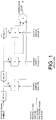
- the pipelined correlator is configured to correlate received signals in real time and at a plurality of time delays.
- the pipelined correlator can be comprised of a plurality of delay devices, a plurality of multipliers, and a plurality of adders forming a summer.
- samples of a received signal are communicated to the delay devices.
- sample refers to a quadrature digital value obtained from a continuous signal in a preceeding digital signal processing.
- the delay devices are configured to delay the samples in time by a pre-determined amount.
- Stored samples are communicated to the complex multipliers.
- the stored samples 1, ..., N can be digital values obtained from a digital signal processing of a received signal or a pseudo-random number sequence.
- the multipliers are configured to statically multiply a stored sample 1, ..., N by a real-time receive signal.
- each multiplier is configured to compute a product utilizing complex multiply arithmetic.
- a first multiplier is configured to multiply a stored sample N by a time delayed sample S N of a received signal.
- a second multiplier is configured to multiply a stored sample N-1 by a time delayed sample S N-1 , and so on.
- the multipliers are also configured to communicate the products of the complex multiply arithmetic to the summer. Upon receipt of the products, the summer adds the same together to obtain a correlation value. If the correlation value magnitude is less than a pre-defined threshold value, then the relative delay is deemed incorrect (i.e., the desired signal is not considered located). If the correlation value magnitude is greater than a pre-defined threshold value, then the relative delay is deemed correct (i.e., the desired signal or correlation peak has been located).
- this pipelined configuration is a real time process which prevents post-processing verification of the correlation index values. Once the incoming signal passes the ideal correlation peak with the stored or internally generated values, the signal can't be re-correlated. More particularly, the pipelined configuration is absent of dynamic abilities, such as an ability to change samples and an ability to double-check a suspected correlation peak. This pipelined configuration is also hardware intensive and computationally inefficient since all possible values use full length correlations. The expected number of arithmetic operations required to obtain the correlation peak increases linearly with both the uncertainty window and the correlation length.
- the phrase "uncertainty window" as used herein refers to the bounded temporal range that includes the minimum and maximum possible signal delay. Correlating over the entire uncertainty window is required to be certain of acquiring the signal.
- This pipelined configuration is further hardware intensive by requiring N dedicated or re-used multipliers. In this regard, it should be appreciated that the pipelined structure can only generate one correlation value per clock cycle. The correlation value represents the sum of all products, where the number of hardware products is the length of the correlation.
- Document WO 0126244 discloses a method of determining delays in a spread spectrum signal transmitted in a communications medium according to a spreading sequence by receiving a composite signal including the spread spectrum signal from the communications medium.
- the composite signal is correlated with the spreading sequence according to a first correlation length, to produce first time-offset correlations of the composite signal with the spreading sequence.
- Selected ones of the first time-offset correlations of the composite signal then are further correlated with the spreading sequence according to a second correlation length that is longer than the first correlation length, to produce second time-offset correlations of the composite signal with the spreading sequence. At least one of the second time-offset correlations may be selected.
- Document WO2004079921 discloses a method and system for acquiring a received impulse radio signal by first searching, with respect to time, a region of the impulse radio signal using a first template signal to locate a block including a signal cell, and second searching, with respect to time, the block using a second template signal to locate the signal cell to acquire the received impulse radio signal.
- Document WO2007086858 discloses a multipath searcher and method includes a programmable decimation filter configured to adjust a sample rate of a received pilot signal.
- a plurality of correlators is configured to compare the received pilot signal to a reference code in a first mode and in a second mode.
- the first mode includes a low resolution search of a search window performed such that the plurality of correlators encompass an entire search window concurrently and the plurality of correlators receives a delayed reference code delayed to correspond with a portion of the search window in which a corresponding correlator performs correlation to identify peaks in the received pilot signal.
- the second mode includes a high resolution search of a refined search window only at or near identified peaks discovered in the first mode. The high resolution search is focused at the peak location by adjusting delays in the plurality of correlators.
- Document US2005130616 discloses a path search and verification method and apparatus for identifying and selecting one or more delays for a receiver.
- a front-end receiver receives a signal having one or more signal images, where each signal image has a corresponding signal delay.
- a tree generator builds a hierarchical delay tree from a plurality of delay nodes, each corresponding to one of the signal delays.
- a tree searcher searches through the delay tree to identify one or more surviving delay nodes, where each surviving delay node corresponds to a candidate delay for the receiver.
- the receiver may also include a state machine comprising a plurality of ordered states for providing candidate delays for the receiver. The state machine stores the candidate delays and shifts the candidate delays between states within the state machine based on the latest results from the tree searcher.
- Document WO0147128 discloses an analog correlation techniques are used in a digital receiver portion of a spread spectrum transceiver to determine when to turn ON given digital receiver components.
- an analog correlator receives the down-converted in-phase and quadrature-phase outputs from the radio section and determines when a received signal is coming up at or near a given noise level.
- a control circuit is coupled to the correlator to selectively activate flash A/D converters in the digital receiver portion of the baseband processor.
- the analog correlator replaces the RSSI for "sniffing" whether a received signal is present.
- Document WO0245288 discloses a receiver unit including a first buffer that receives and stores digitized samples at a particular sample rate and a data processor that retrieves segments of digitized samples from the first buffer and processes the retrieved segments with a particular set of parameters values.
- the data processor is operated based on a processing clock having a frequency that is (e.g., then or more times) higher than the sample rate. Multiple instances of the received signal can be processed by retrieving and processing multiple segments of digitized samples from the first buffer.
- the receiver unit typically further includes a receiver that receives and processes a transmitted signal to provide the digitized samples and a controller that dispatches tasks for the data processor.
- the data processor may include a correlator, a symbol demodulation and combiner, a first accumulator, and a second buffer, or a combination thereof.
- the correlator despreads the retrieved segments of digitized samples with corresponding segments of PN despreading sequences to provide correlated samples, which are further processed by the symbol demodulation and combiner to provide processed symbols.
- the second buffer stores the processed symbols, and can be designed to provide de-interleaving of the processed symbols.
- the adaptive correlation device 200 can be implemented in a receiver configured to synchronize a received signal with an internally generated or stored sample sequence.
- sample refers to a digital value obtained from a continuous signal. It should be understood that the adaptive correlation device 200 performs actions to obtain time delay and phase shift information of the received signal relative to an internally generated or stored signal. This time delay and phase shift information is hereinafter referred to as a correlation value.
- correlation peak value refers to a relative time delay and phase shift providing a maximum correlation between a received signal and an internally generated or stored sample sequence.
- correlation index value refers to a relative delay, often measured in samples, between a received signal and an internally generated or stored sample sequence.
- the correlation peak value and correlation index value can be communicated from the adaptive correlation device 200 to a sampling device (not shown).
- the sampling device (not shown) can be configured to utilize the correlation peak value and correlation index value to correct for transmission time delays occurring in a signal transmission process. More particularly, the correlation index value can be used to correct for propagation time delays occurring in a transmission path. A sequence of correlation peak values can also be used to correct for carrier frequency phase shifts occurring during transmission.
- transmission path refers to a path between a transmitter and a receiver of a communications system that a data communication follows. The path can include, but is not limited to, a communications link existing between the transmitter and the receiver.
- FIG. 3 there is provided a conceptual diagram of a correlation process that can be performed by the adaptive correlation device 200.
- a first sequence of signal samples is from an externally received signal.
- a second sequence of signal samples is from an internally generated or stored signal.
- the first and second sequences of signal samples may be stored in internal memory, may be stored in internal buffers, and/or obtained in real-time.
- the correlation process includes a low-resolution correlation, a medium-resolution correlation, and a fine-resolution correlation.
- the phrase "low-resolution correlation” as used herein refers to a correlation between N1 samples of the received signal and N1 samples of the internally generated or stored sample sequence.
- the phrase “medium-resolution correlation” as used herein refers to a correlation between N2 samples of the received signal and N2 samples of the internally generated or stored sample sequence.
- the phrase “fine-resolution correlation” as used herein refers to a correlation between N3 samples of the received signal and N3 samples of the internally generated or stored sample sequence.
- the values of N1, N2, and N3 are all integers, with N3 > N2 > N1.
- the low-resolution correlation involves selecting a first set of samples A from the received signal and a first set of samples D from the internally generated or stored sample sequence. It should be noted that the sets of samples A, D contain the same number of samples.
- the low-resolution correlation also involves comparing the first set of samples A from the received signal with the first set of samples D from the internally generated or stored sample sequence.
- the medium-resolution correlation involves selecting a second set of samples B from the received signal and a second set of samples E from the internally generated or stored sample sequence. It should be noted that the second sets of samples B, E contain the same number of samples. However, the sets of samples B, E contain a larger number of samples than the first sets of samples A, D. It should also be noted that the second sets of samples B, E contain samples that are independent to the first sets of samples A, D. Upon selecting the second sets of samples B, E, the medium-resolution correlation continues with a comparison of the sets of samples B, E to determine if a sufficient correlation exists between the same.
- the fine-resolution correlation involves selecting a third set of samples C from the received signal and a third set of samples F from the internally generated or stored sample sequence. It should be noted that the third set of samples C, F contain the same number of samples. However, the sets of samples C, F contain a larger number of samples than the second sets of samples B, E. It should also be noted that the third sets of samples C, F contain samples that are independent to both the first sets of samples A, D and the second sets of samples B, E. Upon selecting the third sets of samples C, F, the fine-resolution correlation continues with a comparison of the sets of samples C, F to determine if a sufficient correlation exists between the same.
- a correlation lock is achieved and a correlation index value is computed. It should be noted that any number of intermediate correlation steps may be utilized during this adaptive correlation process. The present invention is not limited to a coarse, medium, and fine resolution correlation. A next correlation process may begin after communicating this correlation index value to the receiver.
- a correlation peak value is computed between sample sets A/D, B/E, or C/F and the correlation peak value does not exceed a pre-defined threshold value
- the correlation process ends with the decision that no sufficient correlation exists.
- the correlation process resumes after stepping sample sets A, B, and C an integer number of samples in time and repeating the process until a sufficient correlation is found. If no correlation is determined to be sufficient, then the correlation process does not achieve a "lock".
- a "correlation lock" refers to proper determination of the relative delay between two (2) signals with a high degree of certainty.
- the correlation lock can be a false positive. Reduction of false positives is one of the benefits of adaptive correlation.
- high degree of certainty means that the likelihood of a lock being declared when the received signal timing is not approximate to that of the reference or when the received signal is not present is low and the likelihood of a correlation peak not being detected when the received signal timing is approximately equal to the reference signal is likewise low.
- FIG. 4 A conceptual diagram of a correlation process implementing a parallel processing architecture is provided in FIG. 4 .
- N is equal to eight (8).
- the invention is not limited in this regard.
- the correlation process includes a low-resolution correlation, a medium-resolution correlation, and fine-resolution correlation.
- the low-resolution correlation involves selecting N sets of samples from the received signal and a first set of samples from the internally generated or stored sample sequence. It should be noted that the sets of samples 1, ..., 8, 25 contain the same number of samples.
- the low-resolution correlation also involves concurrently comparing each of the sets of samples 1, ..., 8 from the received signal with the first set of samples 25 from the internally generated or stored sample sequence to determine if a correlation exists between the same.
- the medium-resolution correlation involves selecting the next N sets of samples from the received signal and a second set of samples from the internally generated or stored sample sequence. It should be noted that the sets of samples 9, .. .,16, 26 contain the same number of samples. However, the sets of samples 9, ..., 16, 26 contain a larger number of samples than the sets of samples 1, ..., 8, 25. It should also be noted that the sets of samples 9,..., 16, 26 are advantageously chosen to contain samples that are independent to the samples contained in the sets of samples 1, ..., 8, 25. Upon selecting the sets of samples 9,..., 16, 26, the medium-resolution correlation continues with a comparison step. This comparison step involves concurrently comparing each of the sets of samples 9, ..., 16 with the set of samples 26 to determine if a sufficient correlation exists between the same.
- the fine-resolution correlation involves selecting the next N sets of samples from the received signal and a third set of samples from the internally generated or stored sample sequence.
- the sets of samples 17, . .., 24, 27 contain the same number of samples. However, the sets of samples 17, ..., 24, 27 contain a larger number of samples than the sets of samples 9, ..., 16, 26. It should also be noted that the sets of samples 17, ..., 24, 27 are advantageously chosen to contain samples that are independent to the samples contained in the sets of samples 9, ..., 16, 26.
- the fine-resolution correlation continues with a comparison step.
- This comparison step involves concurrently comparing each of the sets of samples 17, ..., 24 with the set of samples 27 to determine if a sufficient correlation exists between the same. If a sufficient correlation exists between a set of samples 17, ..., 24 and the set of samples 27, then a correlation peak value and correlation index value are computed and a next process begins.
- FIG. 4 illustrates the ability to transition from a low-resolution correlation to a medium-resolution correlation and from the medium-resolution correlation to a fine-resolution correlation.
- FIG. 4 does not illustrate the ability to transition from the medium-resolution correlation to the low-resolution correlation or from the fine-resolution correlation to the low-resolution correlation.
- a state-based correlation process can be employed for enabling a verification of correlation index values.
- FIG. 5 A conceptual diagram of a state based correlation process is provided in FIG. 5 .
- the state-based correlation process begins with the performance of a first iteration I 1 of a low-resolution correlation state s o .
- N sets of samples are selected from the received signal.
- a first set of samples is also selected from the internally generated or stored sample sequence.
- the sets of samples a, ..., h, y contain the same number of samples.
- the state based correlation process also involves concurrently comparing each of the sets of samples a, ..., h from the received signal with the first set of samples y from the internally generated or stored sample sequence to determine if a sufficient correlation exists between the same.
- the state is transitioned from the low-resolution correlation state s o to a medium-resolution correlation state s 1 .
- the next N sets of samples are selected from the received signal.
- a second set of samples is also selected from the internally generated or stored sample sequence.
- the sets of samples i, ..., p, z contain the same number of samples. However, the sets of samples i, ..., p, z contain a larger number of samples than the sets of samples a, ..., h, y.
- the sets of samples i, ..., p, z contain samples that are advantageously chosen to contain samples independent to the sets of samples a, ..., h, y.
- each of the sets of samples i, ..., p is concurrently compared with the set of samples z to determine if a sufficient correlation exists between the same.
- the state is transitioned from the medium-resolution correlation state s 1 to the low-resolution correlation state s o .
- a next N sets of samples q-x are selected from the received signal.
- a third set of samples zz is also selected from the internally generated or stored sample sequence. It should be noted that the sets of samples q, ..., x, zz contain the same number of samples.
- the sets of samples q, ..., x, zz contain samples having different relative time delays as compared to the samples contained in the sets of samples a, .. ., h, y.
- the correlation process continues with a comparison step. This comparison step involves concurrently comparing each of the sets of samples q, ..., x with the set of samples zz to determine if a correlation exists between the same.
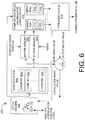
- the adaptive correlation device 200 is comprised of a state machine 602, a counter device 604, buffer memories 606, 608, a complex multiplier-accumulator (CMACC) device 610, a threshold device 614, and an adder 616.
- CMACC complex multiplier-accumulator
- the state machine 602 is configured to transition between a plurality of states s 0 , s 1 , s 2 . More particularly, the state machine 602 is configured to change the state so, s 1 , s 2 of the adaptive correlation device 200 in response to a control signal communicated from the threshold device 614. It should be noted that such a state configuration allows for verification of correlation index values. This verification feature will become evident as the discussion of the adaptive correlation device 200 progresses. The state machine 602 will be described in greater detail below in relation to FIG. 7 .
- FIG. 7 A state diagram of an exemplary embodiment of the state machine 602 is provided in FIG. 7 .
- the state machine is configured to change the state s 0 , s 1 , s 2 of the adaptive correlation device 200 in response to a control signal communicated from the threshold device 614.
- the state machine 602 can change the state of the adaptive correlation device 200 from a low-resolution correlation state s 0 to a medium-resolution correlation state s 1 or from the medium-resolution correlation state s 1 to a fine-resolution correlation state s 2 .
- the state machine 602 can return the state of the adaptive correlation device 200 to the low-resolution correlation state s 0 .
- the state machine 602 can change the state of the adaptive correlation device 200 from the medium-resolution correlation state s 1 to the low-resolution correlation state s 0 or from the fine-resolution correlation state s 2 to the low-resolution correlation state s 0 . Still, the invention is not limited in this regard.
- the counter device 604 is configured to specify memory addresses for reading sets of samples from the buffer memory 606 in a pre-defined order.
- the counter device 604 is also configured to specify memory addresses for reading samples from the buffer memory 608 in a pre-defined order.
- the counter device 604 can be comprised of a plurality of counters 604 1 , 604 2 ,..., 604 i .
- the counters 604 1 , 604 2 ,..., 604 i can be up counters configured to increment by one or more integer value in response to a clock signal.
- Each of the counters 604 1 , 604 2 ,..., 604 i is provided to specify memory addresses for reading sets of samples from the buffer memory 606 and samples from the buffer memory 608 in a pre-defined order during a particular state s 0 , s 1 ,..., s i .
- the counter 604 1 can be utilized when the adaptive correlation device 200 is in its initial state s 0 .
- the counter 604 1 can be configured to increment from a base index value to an integer value n 1 .
- the phrase "base index value" as used herein refers to an integer value representing an initial address of the buffer memories and/or an initial sample of a received signal.
- the base index value can be selected in accordance with the number of times the adaptive correlation device 200 has been transitioned into its initial state s 0 . For example, if the adaptive correlation device 200 is in a first iteration I 1 of the initial state s 0 , then the base index value is equal to zero (0).
- the base index value is equal to a first non-zero integer value, such as eight (8). If the adaptive correlation device 200 is in a third iteration I 3 of the initial state s 0 , then the base index value is equal to a second non-zero integer value, such as sixteen (16). Still, the invention is not limited in this regard.
- the counter 604 2 can be utilized when the adaptive correlation device 200 is in its second state s 1 .
- the counter 604 2 can be configured to increment from an integer value (n 1 +1) to an integer value n 2 .
- the counter 604 3 can be utilized when the adaptive correlation device 200 is in its third state s 2 .
- the counter 604 3 can be configured to increment from an integer value (n 2 +1) to an integer value n 3 , and so on.
- the buffer memory 606 is configured to receive a plurality of received signal samples and store the same in storage locations with sequential addresses.
- the buffer memory 606 is also configured to communicate a set of samples to the CMACC device 610 every clock cycle and in an order defined by the counter device 604.
- the buffer memory 608 is configured to store samples of an internally generated or previously stored sample sequence in storage locations with sequential addresses.
- the buffer memory 608 is also configured to communicate a single sample to the CMACC device 610 every clock cycle and in an order defined by the counter device 604.
- the CMACC device 610 is configured to receive a set of samples from the buffer memory 606 per clock cycle.
- the CMACC device 610 is also configured to receive a sample from the buffer memory 608 per clock cycle.
- the CMACC device 610 is further configured to perform a plurality of complex multiplies and accumulations.
- the CMACC device 610 can be comprised of a plurality of complex multiply-accumulators (CMACCs) 612 1 ,. .., 612 N .
- CMACCs complex multiply-accumulators
- Each CMACC 612 1 ,..., 612 N is configured to perform a complex multiply-accumulation process.
- each CMACC 612 1 , ..., 612 N can be comprised of a complex multiplier 618 1 , ..., 618 N and a complex accumulator 620 1 ,..., 620N.
- Each complex multiplier 618 1 ,..., 618 N can be configured to compute a product during each clock cycle by multiplying a sample from the buffer memory 606 by a sample from a buffer memory 608.
- Each complex multiplier 618 1 ,..., 618 N can also be configured to communicate computed products to a respective complex accumulator 620 1 , ..., 620 N for use in an accumulation process. The accumulation process involves adding the computed products together to obtain an accumulation value.
- Each CMACC 612 1 ,..., 612 N can also be configured to compute the magnitude of the accumulated value via multiplication of the accumulated value with its complex conjugate.
- Each complex accumulator 620 1 ,. .., 620 N can be configured to communicate accumulation values to the threshold device 614.
- the threshold device 614 is configured to receive a value from each of the CMACCs 612 1 ,..., 612 N .
- the threshold device 614 is also configured to compare each received value to a specific threshold value thr o , ..., thr i .
- Each threshold value thr o , ..., thr i is selected in accordance with the state s 0 , s 1 ,..., s i of the adaptive correlation device 200. For example, if the adaptive correlation device 200 is in its initial state s 0 , then the threshold value used in the comparison process is thr o . Similarly, if the adaptive correlation device 200 is in its second state s 1 , then the threshold value used in the comparison process is thr 1 , and so on. Still, the invention is not limited in this regard.
- the threshold device 614 is also configured to communicate a control signal to the state machine 602 based on the outcome of the comparison process. For example, if all accumulation values are less than a given threshold value, then the threshold device 614 communicates a control signal to the state machine 602 indicating that the state machine should revert to the state s 0 and proceed to the next base correlation index. If at least one of the accumulation values is greater than or equal to a given threshold value, then the threshold device 614 communicates a control signal to the state machine 602 indicating that it should proceed to the next subsequent state for a more precise correlation calculation. The threshold device 614 is further configured to perform an arithmetic process to estimate the relative delay between the two (2) sequences within the CMACC correlation window.
- the output value provides an indication of which CMACC(s) 612 1 ,..., 612 N produced an accumulation value greater than or equal to the threshold value.
- the output delay value can be an integer number or a decimal number. For example, if CMACCs 612 1 , 612 2 both produce accumulation values greater than or equal to the threshold value, then the calculated delay will most likely equal a decimal, non-integer delay value.
- the decimal value is determined by some pre-defined arithmetic process, such as an arithmetic process based on center-of-mass or L p norm. Still, the invention is not limited in this regard.
- the threshold device 614 Upon determining an output delay value, the threshold device 614 communicates the same to the adder 616.
- the adder 616 is configured to receive the output value from the threshold device and a base index value from the counter device 604. Upon receipt of these values, the adder 616 adds the same together to obtain a correlation index value.
- the adder 616 is also configured to communicate the correlation index value to a sampling device (not shown).
- FIG. 8 provides an illustration of a process performed by the adaptive correlation device 200 during an iteration I i of a state s i .
- the adaptive correlation device 200 performs sample processing on n1 sets of samples from a received signal per iteration I 1 , ..., I i of a state s 0 , s 1 , ..., s i .
- each set of samples from a received signal is comprised of N samples.
- the variable "N" is an integer value representing the number of CMACCs 612 1 ,..., 612 N comprising the CMACC device 610.
- sets of samples from the buffer memory 606 are communicated to the CMACC device 610 every clock cycle.
- the CMACC device 610 receives a first set of samples ⁇ S 606 0 ,..., S 606 N-1 ⁇ from the buffer memory 606 during a first clock cycle.
- the CMACC device 610 receives a second set of samples ⁇ S 606 1 , ..., S 606 N ⁇ from the buffer memory 606 during a second clock cycle.
- the CMACC device 610 receives a third set of samples ⁇ S 606 2 , ..., S 606 N+1 ⁇ from the buffer memory 606 during a third clock cycle, and so on.
- the invention is not limited in this regard.
- the CMACC device 610 Upon receipt of a set of samples, the CMACC device 610 forwards a sample from the received set of samples to each CMACC 612 1 ,..., 612 N . For example, a sample S 606 0 from the first set of samples is forwarded to the CMACC 612 1 . A sample S 606 1 from the first set of samples is forwarded to the CMACC 612 2 . A sample S 606 2 from the first set of samples is forwarded to the CMACC 612 3 , and so on. Still, the invention is not limited in this regard.
- the CMACC device 610 also receives a sample from the buffer memory 608 every clock cycle. For example, the CMACC device 610 receives a first sample S 608 0 from the buffer memory 608 during a first clock cycle. The CMACC device 610 receives a second sample S 608 1 from the buffer memory 608 during a second clock cycle, and so on. Upon receipt of a sample S 608 0 , ..., S 608 N-1 from the buffer memory 608, the CMACC device 610 forwards the same to each CMACC 612 1 ,..., 612 N .
- Each CMACC 612 1 ,..., 612 N performs actions to complex multiply the received samples to obtain a product P 0 ,..., P n1 .
- each CMACC 612 1 ,..., 612 N complex multiplies a respective sample S 606 0 , ..., S 606 N-1 by a sample S 608 0 to obtain a product P 0 .
- each CMACC 612 1 ,..., 612 N complex multiplies a respective sample S 606 1 ,..., S 606 N by a sample S 608 1 to obtain a product P 1 , and so on.
- the invention is not limited in this regard.
- each CMACC 612 1 ,.. ., 612 N performs actions to accumulate the same. More particularly, each complex accumulator 620 1 ,..., 620 N adds the computed products P 0 ,..., P n1 together to obtain an accumulation value. Each complex accumulator 620 1 , ..., 620 N forwards a respective accumulation value to the threshold device 614. The threshold device 614 determines whether at least one of the accumulation values is equal to or greater than a threshold value thr i .
- the threshold device 614 communicates a low control signal to the state machine 602.
- the state of the adaptive correlation device 200 is either (a) maintained in its initial state s 0 or (b) transitioned from a state s 1 , ..., s 1 to the initial state s 0 .
- the base index value is also incremented by a pre-defined value N.
- a next iteration I i+1 of the CMACC process for the initial state s 0 is then performed.
- the threshold device 614 communicates a high control signal to the state machine 602.
- the state of the adaptive correlation device 200 is transitioned from a state s i to a next state s i+1 .
- the base index value is also incremented by a pre-defined value.
- a CMACC process for the next state s i+1 is then performed or the delay is computed if the state machine is in the highest state.
Landscapes
- Engineering & Computer Science (AREA)
- Physics & Mathematics (AREA)
- General Physics & Mathematics (AREA)
- Mathematical Physics (AREA)
- Computer Networks & Wireless Communication (AREA)
- Signal Processing (AREA)
- Computational Mathematics (AREA)
- Theoretical Computer Science (AREA)
- Mathematical Analysis (AREA)
- Mathematical Optimization (AREA)
- Pure & Applied Mathematics (AREA)
- Data Mining & Analysis (AREA)
- Algebra (AREA)
- Databases & Information Systems (AREA)
- Software Systems (AREA)
- General Engineering & Computer Science (AREA)
- Computing Systems (AREA)
- Mobile Radio Communication Systems (AREA)
- Synchronisation In Digital Transmission Systems (AREA)
- Radar Systems Or Details Thereof (AREA)
- Complex Calculations (AREA)
- Circuits Of Receivers In General (AREA)
Claims (7)
- In einer Korrelationsvorrichtung eines Empfängers in einem Kommunikationssystem implementiertes zustandsbasiertes Korrelationsverfahren, wobei die Korrelationsvorrichtung eine Zustandsmaschine (602), eine Zählervorrichtung (604) und einen Pufferspeicher (606, 608) umfasst, und wobei- die Zustandsmaschine konfiguriert ist, zwischen mehreren Zuständen (s0, s1, s2) zu wechseln;- die Zählvorrichtung eine Vielzahl von Zählern (6041, 6042 ...) umfasst, wobei jeder der Zähler vorgesehen ist, Speicheradressen zum Lesen von Sätzen von Abtastwerten aus dem Pufferspeicher (606) und Abtastwerte aus dem Pufferspeicher (608) in eine vordefinierte Ordnung während eines bestimmten Zustands (s0, s1...) zu spezifizieren;- wobei der Pufferspeicher (606) konfiguriert ist, eine Vielzahl von empfangenen Signalabtastwerten zu empfangen und diese in Speicherplätzen mit sequentiellen Adressen zu speichern;- wobei der Pufferspeicher (608) konfiguriert ist, Abtastwerte einer intern erzeugten oder zuvor gespeicherten Abtastwertfolge in Speicherstellen mit sequentiellen Adressen zu speichern, um Zeit- und Phaseninformationen des an dem Empfänger empfangenen Signals durch Korrelieren von Abtastwerten des empfangenen Signals und Abtastwerten der intern erzeugten oder gespeicherten Abtastfolge zu erhalten,
wobei das Verfahren umfasst:Wechseln eines Korrelationszustands zu einem niedrigauflösenden Korrelationszustand und Ausführen einer ersten Iteration einer niedrigauflösenden Korrelation, wobei die niedrigauflösende Korrelation die folgenden Schritte umfasst:Auswählen erster N Sätze empfangener Signalabtastwerte aus einem empfangenen Signal;Auswählen eines ersten Satzes von Referenzabtastwerten aus einer intern erzeugten oder gespeicherten Abtastfolge;wobei die ersten N Sätze empfangener Signalabtastwerte und der erste Satz von Referenzabtastwerten die gleiche Anzahl von Abtastwerten umfassen; undwobei eine Anfangsadresse der empfangenen Signalabtastwerte und Referenzabtastwerte auf einem ersten der Vielzahl von Zählern basiert, die dem niedrigauflösenden Korrelationszustand (6041) zugeordnet sind;gleichzeitiges Vergleichen jedes der ersten N Sätze empfangener Signalabtastwerte mit dem ersten Satz von Referenzabtastwerten, um zu bestimmen, ob eine ausreichende Korrelation zwischen diesen existiert; wobei eine ausreichende Korrelation existiert, wenn ein Korrelationswert, der mindestens einem der ersten N Sätze empfangener Signalabtastwerte zugeordnet ist, einen vordefinierten Schwellenwert überschreitet;wenn bestimmt ist, dass eine ausreichende Korrelation zwischen mindestens einem der ersten N Sätze empfangener Signalabtastwerte und dem ersten Satz von Referenzabtastwerten existiert, Wechseln des Korrelationszustands zu einem höherauflösenden Korrelationszustand und Ausführen einer ersten Iteration einer höherauflösenden Korrelation, wobei die höherauflösenden Korrelation die folgenden Schritte umfasst: (a) Auswählen zweiter N Sätze empfangener Signalabtastwerte aus einem empfangenen Signal und (b) Auswählen eines zweiten Satzes von Referenzabtastwerten aus der intern erzeugten oder gespeicherten Abtastfolge,wobei die zweiten N Sätze empfangener Signalabtastwerte und der zweite Satz von Referenzabtastwerten die gleiche Anzahl von Abtastwerten umfassen;wobei eine Anfangsadresse der empfangenen Signalabtastwerte und Referenzabtastwerte auf einem zweiten der Vielzahl von Zählern basiert, die dem höherauflösenden Korrelationszustand zugeordnet sind (6042); undwobei die höherauflösende Korrelation ferner den Schritt des gleichzeitigen Vergleichens jedes der zweiten N Sätze empfangener Signalabtastwerte mit dem zweiten Satz von Referenzabtastwerten umfasst, um zu bestimmen, ob eine ausreichende Korrelation zwischen denselben existiert, undwenn bestimmt ist, dass eine ausreichende Korrelation zwischen mindestens einem der ersten N Sätze empfangener Signalabtastwerte und dem ersten Satz von Referenzabtastwerten nicht existiert, Erhöhen des ersten der Vielzahl von dem niedrigauflösenden Korrelationszustand (6041) zugeordneten Zählern und Fortfahren mit dem Verfahrensschritt des Wechselns des Korrelationszustands zu dem niedrigauflösenden Korrelationszustand und Ausführen einer nächsten Iteration der niedrigauflösenden Korrelation, wobei die nächste Iteration der niedrigauflösenden Korrelation den Schritt des Auswählens zweiter N Sätze empfangener Signalabtastwerte von einem empfangenen Signal und eines zweiten Satzes von Referenzabtastwerten aus der intern erzeugten oder gespeicherten Abtastfolge umfasst, wobei die zweiten N Sätze empfangener Signalabtastwerte und der zweite Satz von Referenzabtastwerten die gleiche Anzahl von Abtastwerten umfassen. - Verfahren nach Anspruch 1, wobei die zweiten N Sätze empfangener Signalabtastwerte in der höherauflösenden Korrelation eine Anzahl von Abtastwerten umfassen, die größer sein können als die ersten N Sätze empfangener Signalabtastwerte.
- Verfahren nach Anspruch 1, wobei die zweiten N Sätze empfangener Signalabtastwerte in der höherauflösenden Korrelation Abtastwerte umfassen, die zeitlich verzögert sind, verglichen mit Abtastwerten, die in den ersten N Sätzen von Referenzsignalabtastwerten enthalten sind.
- Verfahren nach Anspruch 1, ferner umfassend Berechnen eines Korrelationsindexwerts, wenn bestimmt ist, dass eine ausreichende Korrelation zwischen mindestens einem der zweiten N Sätze empfangener Signalabtastwerte und dem zweiten Satz von Referenzabtastwerten in der höherauflösenden Korrelation existiert.
- Verfahren nach Anspruch 1, wobei die höherauflösende Korrelation auf unabhängigen Sätzen von Abtastwerten mit den gleichen relativen Verzögerungen wie die niedrigauflösenden Referenzabtastwerte arbeitet.
- Verfahren nach Anspruch 1, wobei die zweiten N Sätze empfangener Signalabtastwerte in der nächsten Iteration der niedrigauflösenden Korrelation die gleiche Anzahl von Abtastwerten wie die ersten N Sätze empfangener Signalabtastwerte umfassen.
- Verfahren nach Anspruch 1, wobei die zweiten N Sätze empfangener Signalabtastwerte in der nächsten Iteration der niedrigauflösenden Korrelation Abtastwerte umfassen, die zeitlich verzögert sind, verglichen mit Abtastwerten, die in den ersten N Sätzen empfangener Signalabtastwerte enthalten sind.
Applications Claiming Priority (2)
| Application Number | Priority Date | Filing Date | Title |
|---|---|---|---|
| US12/131,386 US8064552B2 (en) | 2008-06-02 | 2008-06-02 | Adaptive correlation |
| PCT/US2009/045916 WO2009149051A2 (en) | 2008-06-02 | 2009-06-02 | Adaptive correlation |
Publications (2)
| Publication Number | Publication Date |
|---|---|
| EP2294518A2 EP2294518A2 (de) | 2011-03-16 |
| EP2294518B1 true EP2294518B1 (de) | 2017-09-06 |
Family
ID=41379801
Family Applications (1)
| Application Number | Title | Priority Date | Filing Date |
|---|---|---|---|
| EP09759212.5A Active EP2294518B1 (de) | 2008-06-02 | 2009-06-02 | Adaptive korrelation |
Country Status (6)
| Country | Link |
|---|---|
| US (1) | US8064552B2 (de) |
| EP (1) | EP2294518B1 (de) |
| JP (1) | JP2011525729A (de) |
| KR (1) | KR101253870B1 (de) |
| CA (1) | CA2726448A1 (de) |
| WO (1) | WO2009149051A2 (de) |
Families Citing this family (47)
| Publication number | Priority date | Publication date | Assignee | Title |
|---|---|---|---|---|
| US8312551B2 (en) | 2007-02-15 | 2012-11-13 | Harris Corporation | Low level sequence as an anti-tamper Mechanism |
| US7937427B2 (en) * | 2007-04-19 | 2011-05-03 | Harris Corporation | Digital generation of a chaotic numerical sequence |
| US7921145B2 (en) * | 2007-05-22 | 2011-04-05 | Harris Corporation | Extending a repetition period of a random sequence |
| US8611530B2 (en) | 2007-05-22 | 2013-12-17 | Harris Corporation | Encryption via induced unweighted errors |
| US7995757B2 (en) | 2007-05-31 | 2011-08-09 | Harris Corporation | Closed galois field combination |
| US7962540B2 (en) * | 2007-06-07 | 2011-06-14 | Harris Corporation | Mixed radix number generator with chosen statistical artifacts |
| US7970809B2 (en) * | 2007-06-07 | 2011-06-28 | Harris Corporation | Mixed radix conversion with a priori defined statistical artifacts |
| US7974413B2 (en) * | 2007-06-07 | 2011-07-05 | Harris Corporation | Spread spectrum communications system and method utilizing chaotic sequence |
| US8005221B2 (en) * | 2007-08-01 | 2011-08-23 | Harris Corporation | Chaotic spread spectrum communications system receiver |
| US7995749B2 (en) * | 2007-10-30 | 2011-08-09 | Harris Corporation | Cryptographic system configured for extending a repetition period of a random sequence |
| US8180055B2 (en) | 2008-02-05 | 2012-05-15 | Harris Corporation | Cryptographic system incorporating a digitally generated chaotic numerical sequence |
| US8363830B2 (en) | 2008-02-07 | 2013-01-29 | Harris Corporation | Cryptographic system configured to perform a mixed radix conversion with a priori defined statistical artifacts |
| US8040937B2 (en) * | 2008-03-26 | 2011-10-18 | Harris Corporation | Selective noise cancellation of a spread spectrum signal |
| US8139764B2 (en) | 2008-05-06 | 2012-03-20 | Harris Corporation | Closed galois field cryptographic system |
| US8320557B2 (en) | 2008-05-08 | 2012-11-27 | Harris Corporation | Cryptographic system including a mixed radix number generator with chosen statistical artifacts |
| US8200728B2 (en) * | 2008-05-29 | 2012-06-12 | Harris Corporation | Sine/cosine generator |
| US8145692B2 (en) | 2008-05-29 | 2012-03-27 | Harris Corporation | Digital generation of an accelerated or decelerated chaotic numerical sequence |
| US8064552B2 (en) | 2008-06-02 | 2011-11-22 | Harris Corporation | Adaptive correlation |
| US8068571B2 (en) | 2008-06-12 | 2011-11-29 | Harris Corporation | Featureless coherent chaotic amplitude modulation |
| US8325702B2 (en) * | 2008-08-29 | 2012-12-04 | Harris Corporation | Multi-tier ad-hoc network in which at least two types of non-interfering waveforms are communicated during a timeslot |
| US8165065B2 (en) * | 2008-10-09 | 2012-04-24 | Harris Corporation | Ad-hoc network acquisition using chaotic sequence spread waveform |
| US8406276B2 (en) | 2008-12-29 | 2013-03-26 | Harris Corporation | Communications system employing orthogonal chaotic spreading codes |
| US8351484B2 (en) | 2008-12-29 | 2013-01-08 | Harris Corporation | Communications system employing chaotic spreading codes with static offsets |
| US8457077B2 (en) | 2009-03-03 | 2013-06-04 | Harris Corporation | Communications system employing orthogonal chaotic spreading codes |
| US8428102B2 (en) | 2009-06-08 | 2013-04-23 | Harris Corporation | Continuous time chaos dithering |
| US8509284B2 (en) | 2009-06-08 | 2013-08-13 | Harris Corporation | Symbol duration dithering for secured chaotic communications |
| US8428103B2 (en) | 2009-06-10 | 2013-04-23 | Harris Corporation | Discrete time chaos dithering |
| US8385385B2 (en) | 2009-07-01 | 2013-02-26 | Harris Corporation | Permission-based secure multiple access communication systems |
| US8369376B2 (en) | 2009-07-01 | 2013-02-05 | Harris Corporation | Bit error rate reduction in chaotic communications |
| US8363700B2 (en) | 2009-07-01 | 2013-01-29 | Harris Corporation | Rake receiver for spread spectrum chaotic communications systems |
| US8379689B2 (en) | 2009-07-01 | 2013-02-19 | Harris Corporation | Anti-jam communications having selectively variable peak-to-average power ratio including a chaotic constant amplitude zero autocorrelation waveform |
| US8428104B2 (en) | 2009-07-01 | 2013-04-23 | Harris Corporation | Permission-based multiple access communications systems |
| US8406352B2 (en) | 2009-07-01 | 2013-03-26 | Harris Corporation | Symbol estimation for chaotic spread spectrum signal |
| US8340295B2 (en) * | 2009-07-01 | 2012-12-25 | Harris Corporation | High-speed cryptographic system using chaotic sequences |
| US8848909B2 (en) | 2009-07-22 | 2014-09-30 | Harris Corporation | Permission-based TDMA chaotic communication systems |
| US8369377B2 (en) * | 2009-07-22 | 2013-02-05 | Harris Corporation | Adaptive link communications using adaptive chaotic spread waveform |
| US8345725B2 (en) | 2010-03-11 | 2013-01-01 | Harris Corporation | Hidden Markov Model detection for spread spectrum waveforms |
| GB201015730D0 (en) | 2010-09-20 | 2010-10-27 | Novelda As | Continuous time cross-correlator |
| GB201015729D0 (en) | 2010-09-20 | 2010-10-27 | Novelda As | Pulse generator |
| US8654819B2 (en) | 2011-06-22 | 2014-02-18 | Harris Corporation | Systems and methods for pulse rotation modulation encoding and decoding |
| GB2501309A (en) | 2012-04-20 | 2013-10-23 | Ibm | Using derivatives to compare event data sets. |
| WO2016102999A1 (en) * | 2014-12-24 | 2016-06-30 | Institut Mines-Telecom | Method for transient change detection with adaptive sampling, and detector implementing the method |
| US10708086B2 (en) * | 2016-01-19 | 2020-07-07 | National Instruments Corporation | Channel sounding techniques |
| EP3246824A1 (de) | 2016-05-20 | 2017-11-22 | Fraunhofer-Gesellschaft zur Förderung der angewandten Forschung e.V. | Vorrichtung zur bestimmung von ähnlichkeitsinformationen, verfahren zur bestimmung von ähnlichkeitsinformationen, vorrichtung zur bestimmung von autokorrelationsinformationen, vorrichtung zur bestimmung von kreuzkorrelationsinformationen und computerprogramm |
| US10277269B2 (en) * | 2016-12-09 | 2019-04-30 | The Boeing Company | Phased array beam tracking using beam gain coding |
| WO2018200591A1 (en) | 2017-04-24 | 2018-11-01 | Chaos Prime, Inc. | Communication system employing chaotic sequence based frequency shift keying spreading signals |
| WO2019046822A1 (en) * | 2017-08-31 | 2019-03-07 | Chaos Prime, Inc. | IMPLICIT TRANSFER CORRELATION TECHNIQUES FOR ARBITRATED WAVEFORM SPECTRUM WAVEFORMS |
Citations (3)
| Publication number | Priority date | Publication date | Assignee | Title |
|---|---|---|---|---|
| WO2001047128A1 (en) * | 1999-12-22 | 2001-06-28 | Koninklijke Philips Electronics N.V. | Method for extending digital receiver sensitivity using analog correlation |
| WO2002045288A2 (en) * | 2000-11-27 | 2002-06-06 | Qualcomm Incorporated | Method and apparatus for processing a received signal in a communications system |
| US20050130616A1 (en) * | 2003-12-15 | 2005-06-16 | Khayrallah Ali S. | Method for path searching and verification |
Family Cites Families (125)
| Publication number | Priority date | Publication date | Assignee | Title |
|---|---|---|---|---|
| FR1501059A (fr) | 1966-09-26 | 1967-11-10 | Csf | Nouveau générateur de clé |
| GB1198263A (en) * | 1967-06-06 | 1970-07-08 | Nat Res Dev | Improvements in or relating to Digital Differential Analysers |
| US4646326A (en) * | 1983-10-20 | 1987-02-24 | Motorola Inc. | QAM modulator circuit |
| US4703507A (en) * | 1984-04-05 | 1987-10-27 | Holden Thomas W | Noise reduction system |
| ATE116081T1 (de) * | 1989-08-24 | 1995-01-15 | Philips Nv | Verfahren und einrichtung zur decodierung von wortgeschützten codewörtern durch einen nichtbinären bch-code gegen mindestens einen symbolfehler. |
| US5077793A (en) * | 1989-09-29 | 1991-12-31 | The Boeing Company | Residue number encryption and decryption system |
| US5007087A (en) * | 1990-04-16 | 1991-04-09 | Loral Aerospace Corp. | Method and apparatus for generating secure random numbers using chaos |
| US5048086A (en) * | 1990-07-16 | 1991-09-10 | Hughes Aircraft Company | Encryption system based on chaos theory |
| US5319735A (en) * | 1991-12-17 | 1994-06-07 | Bolt Beranek And Newman Inc. | Embedded signalling |
| US5297206A (en) * | 1992-03-19 | 1994-03-22 | Orton Glenn A | Cryptographic method for communication and electronic signatures |
| US5276633A (en) * | 1992-08-14 | 1994-01-04 | Harris Corporation | Sine/cosine generator and method |
| US5811998A (en) * | 1993-01-28 | 1998-09-22 | Digital Equipment Corporation | State machine phase lock loop |
| US5412687A (en) * | 1993-10-15 | 1995-05-02 | Proxim Incorporated | Digital communications equipment using differential quaternary frequency shift keying |
| US6614914B1 (en) * | 1995-05-08 | 2003-09-02 | Digimarc Corporation | Watermark embedder and reader |
| JPH088780A (ja) * | 1994-06-23 | 1996-01-12 | Toshiba Corp | 相関器及びスペクトル拡散通信システム |
| JP2895398B2 (ja) * | 1994-07-20 | 1999-05-24 | 沖電気工業株式会社 | 同期捕捉方法 |
| JP2895399B2 (ja) * | 1994-07-20 | 1999-05-24 | 沖電気工業株式会社 | 同期追従方法 |
| US5646997A (en) * | 1994-12-14 | 1997-07-08 | Barton; James M. | Method and apparatus for embedding authentication information within digital data |
| US6014446A (en) * | 1995-02-24 | 2000-01-11 | Motorola, Inc. | Apparatus for providing improved encryption protection in a communication system |
| US5598476A (en) * | 1995-04-20 | 1997-01-28 | United Technologies Automotive, Inc. | Random clock composition-based cryptographic authentication process and locking system |
| US5937000A (en) * | 1995-09-06 | 1999-08-10 | Solana Technology Development Corporation | Method and apparatus for embedding auxiliary data in a primary data signal |
| US5757923A (en) * | 1995-09-22 | 1998-05-26 | Ut Automotive Dearborn, Inc. | Method of generating secret identification numbers |
| JPH09148980A (ja) * | 1995-11-22 | 1997-06-06 | Sony Corp | パイロット信号検出方法、パイロット信号検出装置及び移動局受信装置 |
| JP3992742B2 (ja) * | 1996-05-20 | 2007-10-17 | コーニンクレッカ フィリップス エレクトロニクス エヌ ヴィ | データブロックおよび鍵を非線形的に結合する暗号方法および装置 |
| WO1998001964A1 (en) * | 1996-07-05 | 1998-01-15 | Clifford Harris | Modular transmission system and method |
| US7190681B1 (en) * | 1996-07-10 | 2007-03-13 | Wu William W | Error coding in asynchronous transfer mode, internet and satellites |
| US5963460A (en) | 1996-12-17 | 1999-10-05 | Metaflow Technologies, Inc. | Apparatus for computing transcendental functions quickly |
| US6331974B1 (en) * | 1997-06-23 | 2001-12-18 | The Regents Of The University Of California | Chaotic digital code-division multiple access (CDMA) communication systems |
| US5852630A (en) * | 1997-07-17 | 1998-12-22 | Globespan Semiconductor, Inc. | Method and apparatus for a RADSL transceiver warm start activation procedure with precoding |
| DE19733829C2 (de) * | 1997-08-05 | 2000-02-24 | Micronas Semiconductor Holding | Verfahren zum Verschlüsseln bzw. Entschlüsseln einer Datenfolge |
| US6633226B1 (en) * | 1997-08-18 | 2003-10-14 | X-Cyte, Inc. | Frequency hopping spread spectrum passive acoustic wave identification device |
| US6078611A (en) * | 1997-09-16 | 2000-06-20 | Motorola, Inc. | Rake receiver and finger management method for spread spectrum communication |
| US6038317A (en) * | 1997-12-24 | 2000-03-14 | Magliveras; Spyros S. | Secret key cryptosystem and method utilizing factorizations of permutation groups of arbitrary order 2l |
| US6285761B1 (en) | 1998-03-04 | 2001-09-04 | Lucent Technologies, Inc. | Method for generating pseudo-random numbers |
| US6754251B1 (en) * | 1998-03-09 | 2004-06-22 | Texas Instruments Incorporated | Spread-spectrum telephony with accelerated code acquisition |
| US5924980A (en) * | 1998-03-11 | 1999-07-20 | Siemens Corporate Research, Inc. | Method and apparatus for adaptively reducing the level of noise in an acquired signal |
| US6141786A (en) * | 1998-06-04 | 2000-10-31 | Intenational Business Machines Corporation | Method and apparatus for performing arithmetic operations on Galois fields and their extensions |
| US5900835A (en) * | 1998-07-09 | 1999-05-04 | The United States Of America As Represented By The Secretary Of The Navy | Coherent hidden markov model |
| US6980656B1 (en) * | 1998-07-17 | 2005-12-27 | Science Applications International Corporation | Chaotic communication system and method using modulation of nonreactive circuit elements |
| US6304556B1 (en) * | 1998-08-24 | 2001-10-16 | Cornell Research Foundation, Inc. | Routing and mobility management protocols for ad-hoc networks |
| US6363104B1 (en) * | 1998-10-02 | 2002-03-26 | Ericsson Inc. | Method and apparatus for interference cancellation in a rake receiver |
| US7277540B1 (en) * | 1999-01-20 | 2007-10-02 | Kabushiki Kaisha Toshiba | Arithmetic method and apparatus and crypto processing apparatus for performing multiple types of cryptography |
| US6823068B1 (en) * | 1999-02-01 | 2004-11-23 | Gideon Samid | Denial cryptography based on graph theory |
| US6377782B1 (en) * | 1999-03-01 | 2002-04-23 | Mediacell, Inc. | Method and apparatus for communicating between a client device and a linear broadband network |
| US6304216B1 (en) * | 1999-03-30 | 2001-10-16 | Conexant Systems, Inc. | Signal detector employing correlation analysis of non-uniform and disjoint sample segments |
| FI107094B (fi) * | 1999-05-10 | 2001-05-31 | Nokia Mobile Phones Ltd | Menetelmä päivittää koodigeneraattorin lineaarinen palautesiirtorekisteri |
| US6307878B1 (en) * | 1999-06-03 | 2001-10-23 | Dspc Technologies Ltd | Cellular telephony searcher |
| US6570909B1 (en) * | 1999-07-09 | 2003-05-27 | Nokia Mobile Phones | Interference suppression in a CDMA receiver |
| US20020099746A1 (en) * | 1999-07-26 | 2002-07-25 | Tie Teck Sing | T-sequence apparatus and method for general deterministic polynomial-time primality testing and composite factoring |
| US6744893B1 (en) * | 1999-08-25 | 2004-06-01 | Southwest Research Institute | Receiver estimation engine for a chaotic system |
| US6377615B1 (en) | 1999-09-30 | 2002-04-23 | Ericsson Inc. | Apparatus and methods for receiving information using variable length accumulation searchers |
| US7200225B1 (en) * | 1999-11-12 | 2007-04-03 | Richard Schroeppel | Elliptic curve point ambiguity resolution apparatus and method |
| US7596170B2 (en) * | 2000-02-28 | 2009-09-29 | Aeroastro, Inc. | Coherent detection without transmission preamble |
| US6993016B1 (en) * | 2000-11-16 | 2006-01-31 | Juniper Networks, Inc. | Methods and apparatus for transmission of analog channels over digital packet networks |
| US7010559B2 (en) * | 2000-11-14 | 2006-03-07 | Parkervision, Inc. | Method and apparatus for a parallel correlator and applications thereof |
| US7170997B2 (en) * | 2000-12-07 | 2007-01-30 | Cryptico A/S | Method of generating pseudo-random numbers in an electronic device, and a method of encrypting and decrypting electronic data |
| US6732127B2 (en) * | 2001-01-10 | 2004-05-04 | Hewlett-Packard Development Company, L.P. | Verifiable random number generator using chaos |
| JP4188571B2 (ja) * | 2001-03-30 | 2008-11-26 | 株式会社日立製作所 | 情報処理装置の演算方法および耐タンパ演算攪乱実装方式 |
| GB2374258B (en) * | 2001-04-05 | 2004-03-31 | Ibm | Method and apparatus for encryption of data |
| US7233970B2 (en) * | 2001-05-02 | 2007-06-19 | Cipher Corporation Limited | Computational method, system, and apparatus |
| US7218734B2 (en) * | 2001-05-02 | 2007-05-15 | Nciper Corporation Limited | Ring arithmetic method, system, and apparatus |
| US7076065B2 (en) * | 2001-05-11 | 2006-07-11 | Lockheed Martin Corporation | Chaotic privacy system and method |
| US6735606B2 (en) * | 2001-05-15 | 2004-05-11 | Qualcomm Incorporated | Multi-sequence fast slewing pseudorandom noise generator |
| US7027598B1 (en) * | 2001-09-19 | 2006-04-11 | Cisco Technology, Inc. | Residue number system based pre-computation and dual-pass arithmetic modular operation approach to implement encryption protocols efficiently in electronic integrated circuits |
| US6456648B1 (en) * | 2001-10-01 | 2002-09-24 | Interdigital Technology Corporation | Code tracking loop with automatic power normalization |
| WO2003036607A1 (en) * | 2001-10-25 | 2003-05-01 | Fujitsu Limited | Display control device |
| JP2003216037A (ja) * | 2001-11-16 | 2003-07-30 | Yazaki Corp | 暗号キー、暗号化装置、暗号化復号化装置、暗号キー管理装置及び復号化装置 |
| US7269198B1 (en) * | 2001-11-19 | 2007-09-11 | Bbn Technologies Corp. | Systems and methods for beaconing in wireless networks with low probability of detection |
| US6766345B2 (en) * | 2001-11-30 | 2004-07-20 | Analog Devices, Inc. | Galois field multiplier system |
| JP2003218835A (ja) * | 2002-01-18 | 2003-07-31 | Mitsubishi Electric Corp | スペクトル拡散送信装置及びスペクトル拡散受信装置 |
| FR2837331B1 (fr) * | 2002-03-13 | 2004-06-18 | Canon Kk | Procede d'entrelacement d'une sequence binaire |
| US7010055B2 (en) * | 2002-06-27 | 2006-03-07 | Motorola, Inc. | System implementing closed loop transmit diversity and method thereof |
| FR2844891A1 (fr) * | 2002-09-20 | 2004-03-26 | St Microelectronics Sa | Masquage de donnees decomposees dans un systeme de residus |
| EP1420542A1 (de) * | 2002-11-12 | 2004-05-19 | STMicroelectronics S.r.l. | Verfahren und Vorrichtung zur chaotischen Erzeugung einer Pseudozufallsfolge |
| JP4098096B2 (ja) * | 2003-01-06 | 2008-06-11 | 三菱電機株式会社 | スペクトル拡散受信装置 |
| US7292619B2 (en) | 2003-03-03 | 2007-11-06 | Mitsubishi Electric Research Laboratories | Method and system for acquiring ultra-wide-bandwidth communications signals using sequential block searches |
| JP2004279784A (ja) | 2003-03-17 | 2004-10-07 | Nippon Telegr & Teleph Corp <Ntt> | 有限体上演算装置、及び有限体上演算プログラム |
| US7272168B2 (en) * | 2003-04-01 | 2007-09-18 | Nokia Siemens Networks Oy | Determining the correlation between received samples and available replica samples |
| US7328228B2 (en) * | 2003-09-02 | 2008-02-05 | Sap Aktiengesellschaft | Mapping pseudo-random numbers to predefined number ranges |
| KR100543101B1 (ko) * | 2003-10-23 | 2006-01-20 | 학교법인 배재학당 | 시간지연가변 되먹임 혼돈시스템을 이용한 암호화 및 통신 장치와 그 방법 |
| RU2276458C2 (ru) * | 2003-11-26 | 2006-05-10 | Институт радиотехники и электроники Российской Академии Наук | Способ прямохаотической передачи информации с заданной спектральной маской |
| US7512645B2 (en) * | 2004-03-19 | 2009-03-31 | Texas Instruments Incorporated | System and method for generating pseudorandom numbers |
| US7150399B2 (en) * | 2004-06-09 | 2006-12-19 | Ricoh Co., Ltd. | Embedding barcode data in an auxiliary field of an image file |
| US7078981B2 (en) * | 2004-07-27 | 2006-07-18 | Lucent Technologies Inc. | 16 QAM modulator and method of 16 QAM modulation |
| US7532721B2 (en) * | 2004-10-28 | 2009-05-12 | Cisco Technology, Inc. | Implementation of a switch-box using a subfield method |
| US7512647B2 (en) * | 2004-11-22 | 2009-03-31 | Analog Devices, Inc. | Condensed Galois field computing system |
| US20060209932A1 (en) * | 2005-03-18 | 2006-09-21 | Qualcomm Incorporated | Channel estimation for single-carrier systems |
| ITVA20050027A1 (it) * | 2005-05-03 | 2006-11-04 | St Microelectronics Srl | Metodo di generazione di successioni di numeri o bit pseudo casuali |
| US7830214B2 (en) * | 2005-11-29 | 2010-11-09 | Samsung Electronics Co., Ltd. | Adjustable chaotic signal generator using pulse modulation for ultra wideband (UWB) communications and chaotic signal generating method thereof |
| WO2007065297A1 (en) | 2005-12-07 | 2007-06-14 | Zte Corporation | Method and device for removing narrow band interference in spreading frequency system |
| JP5227807B2 (ja) * | 2006-01-27 | 2013-07-03 | トムソン ライセンシング | 多重解像度/マルチパスサーチャの方法及び装置 |
| US7688878B2 (en) | 2006-03-16 | 2010-03-30 | The Boeing Company | Method and device of peak detection in preamble synchronization for direct sequence spread spectrum communication |
| KR100723222B1 (ko) * | 2006-03-28 | 2007-05-29 | 삼성전기주식회사 | 펄스 세이핑 기법을 이용한 카오스 신호 송신장치 |
| KR100732382B1 (ko) * | 2006-04-27 | 2007-06-27 | 주식회사 팬택 | 직교 주파수 분할 다중 접속 이동통신 단말기의 프리앰블획득 장치 및 방법 |
| FR2903200B1 (fr) * | 2006-06-29 | 2008-12-19 | Thales Sa | Stabilisation hybride d'images pour camera video |
| US9203438B2 (en) * | 2006-07-12 | 2015-12-01 | Ternarylogic Llc | Error correction by symbol reconstruction in binary and multi-valued cyclic codes |
| LU91292B1 (en) | 2006-12-01 | 2008-06-02 | European Gsa | New Chaotic Spreading Codes for Galileo |
| US7643537B1 (en) * | 2007-01-23 | 2010-01-05 | L-3 Communications, Corp. | Spread spectrum signal detection with inhibiting for known sidelobe locations |
| WO2008099367A2 (en) | 2007-02-15 | 2008-08-21 | Koninklijke Philips Electronics N.V. | Coordination in wireless networks having devices with different physical layer transmission schemes |
| US8312551B2 (en) * | 2007-02-15 | 2012-11-13 | Harris Corporation | Low level sequence as an anti-tamper Mechanism |
| US7937427B2 (en) * | 2007-04-19 | 2011-05-03 | Harris Corporation | Digital generation of a chaotic numerical sequence |
| US7921145B2 (en) | 2007-05-22 | 2011-04-05 | Harris Corporation | Extending a repetition period of a random sequence |
| US8611530B2 (en) * | 2007-05-22 | 2013-12-17 | Harris Corporation | Encryption via induced unweighted errors |
| JP4917478B2 (ja) * | 2007-05-25 | 2012-04-18 | 株式会社ケーヒン | 乱数発生装置及び車両制御装置 |
| US7995757B2 (en) * | 2007-05-31 | 2011-08-09 | Harris Corporation | Closed galois field combination |
| US7962540B2 (en) | 2007-06-07 | 2011-06-14 | Harris Corporation | Mixed radix number generator with chosen statistical artifacts |
| US7970809B2 (en) | 2007-06-07 | 2011-06-28 | Harris Corporation | Mixed radix conversion with a priori defined statistical artifacts |
| US7974413B2 (en) | 2007-06-07 | 2011-07-05 | Harris Corporation | Spread spectrum communications system and method utilizing chaotic sequence |
| US8005221B2 (en) * | 2007-08-01 | 2011-08-23 | Harris Corporation | Chaotic spread spectrum communications system receiver |
| US7995749B2 (en) * | 2007-10-30 | 2011-08-09 | Harris Corporation | Cryptographic system configured for extending a repetition period of a random sequence |
| US20090122926A1 (en) * | 2007-11-13 | 2009-05-14 | Texas Instruments Incorporated | Data throughput in an interference-rich wireless environment |
| US8180055B2 (en) * | 2008-02-05 | 2012-05-15 | Harris Corporation | Cryptographic system incorporating a digitally generated chaotic numerical sequence |
| US8363830B2 (en) * | 2008-02-07 | 2013-01-29 | Harris Corporation | Cryptographic system configured to perform a mixed radix conversion with a priori defined statistical artifacts |
| US8040937B2 (en) * | 2008-03-26 | 2011-10-18 | Harris Corporation | Selective noise cancellation of a spread spectrum signal |
| US8139764B2 (en) * | 2008-05-06 | 2012-03-20 | Harris Corporation | Closed galois field cryptographic system |
| US8320557B2 (en) * | 2008-05-08 | 2012-11-27 | Harris Corporation | Cryptographic system including a mixed radix number generator with chosen statistical artifacts |
| US8200728B2 (en) | 2008-05-29 | 2012-06-12 | Harris Corporation | Sine/cosine generator |
| US8145692B2 (en) | 2008-05-29 | 2012-03-27 | Harris Corporation | Digital generation of an accelerated or decelerated chaotic numerical sequence |
| US8064552B2 (en) | 2008-06-02 | 2011-11-22 | Harris Corporation | Adaptive correlation |
| US8068571B2 (en) | 2008-06-12 | 2011-11-29 | Harris Corporation | Featureless coherent chaotic amplitude modulation |
| US8159938B2 (en) | 2008-06-23 | 2012-04-17 | C.H.E.S.S. Embedded Technology B.V. | Broadcast-only distributed wireless network |
| US8891756B2 (en) * | 2008-10-30 | 2014-11-18 | Certicom Corp. | Collision-resistant elliptic curve hash functions |
| US7974146B2 (en) * | 2008-12-19 | 2011-07-05 | Micron Technology, Inc. | Wordline temperature compensation |
| US8428102B2 (en) | 2009-06-08 | 2013-04-23 | Harris Corporation | Continuous time chaos dithering |
| US8428103B2 (en) | 2009-06-10 | 2013-04-23 | Harris Corporation | Discrete time chaos dithering |
-
2008
- 2008-06-02 US US12/131,386 patent/US8064552B2/en active Active
-
2009
- 2009-06-02 WO PCT/US2009/045916 patent/WO2009149051A2/en not_active Ceased
- 2009-06-02 CA CA2726448A patent/CA2726448A1/en not_active Abandoned
- 2009-06-02 KR KR1020107029878A patent/KR101253870B1/ko not_active Expired - Fee Related
- 2009-06-02 EP EP09759212.5A patent/EP2294518B1/de active Active
- 2009-06-02 JP JP2011512577A patent/JP2011525729A/ja active Pending
Patent Citations (3)
| Publication number | Priority date | Publication date | Assignee | Title |
|---|---|---|---|---|
| WO2001047128A1 (en) * | 1999-12-22 | 2001-06-28 | Koninklijke Philips Electronics N.V. | Method for extending digital receiver sensitivity using analog correlation |
| WO2002045288A2 (en) * | 2000-11-27 | 2002-06-06 | Qualcomm Incorporated | Method and apparatus for processing a received signal in a communications system |
| US20050130616A1 (en) * | 2003-12-15 | 2005-06-16 | Khayrallah Ali S. | Method for path searching and verification |
Also Published As
| Publication number | Publication date |
|---|---|
| WO2009149051A2 (en) | 2009-12-10 |
| JP2011525729A (ja) | 2011-09-22 |
| CA2726448A1 (en) | 2009-12-10 |
| EP2294518A2 (de) | 2011-03-16 |
| US8064552B2 (en) | 2011-11-22 |
| KR20110028321A (ko) | 2011-03-17 |
| US20090296860A1 (en) | 2009-12-03 |
| KR101253870B1 (ko) | 2013-04-16 |
| WO2009149051A3 (en) | 2011-04-28 |
Similar Documents
| Publication | Publication Date | Title |
|---|---|---|
| EP2294518B1 (de) | Adaptive korrelation | |
| KR100736986B1 (ko) | 프로그램가능한 정합 필터 탐색기 | |
| US6470000B1 (en) | Shared correlator system and method for direct-sequence CDMA demodulation | |
| EP1241817A1 (de) | Empfänger | |
| EP0994573A2 (de) | Verfahren und Vorrichtung zur Erzeugung von mehreren PN-Vektoren für angepasste Filter in einem CDMA Demodulator | |
| JP4350271B2 (ja) | Cdma通信システムの受信器における拡散コード同期取得方法及びその装置 | |
| KR0173904B1 (ko) | 직접 확산 부호 분할 다중 접속 시스템용 레이크수신장치 | |
| JP2006517079A (ja) | サブ・シンボルの並列干渉打消し | |
| US7010024B1 (en) | Matched filter and spread spectrum receiver | |
| JP2006501775A (ja) | パイプライン型ベクトル処理を用いて直接シーケンス・スペクトラム拡散信号を検出するシステムおよび方法 | |
| KR100268445B1 (ko) | 획득 시간을 단축할수 있는 확산 대역 통신 시스템의 수신장치 | |
| CN1198049A (zh) | 用于减少硬件成本和改善搜索性能的瑞克接收机 | |
| JP2003332946A (ja) | Umts−fdd受信器用コードグループ採取手順 | |
| US6601078B1 (en) | Time-efficient real-time correlator | |
| KR100655660B1 (ko) | 무선랜 프리앰블 신호 검출 장치 및 그의 신호 검출 및타이밍 검출 방법 | |
| TW200405740A (en) | Mitigation of interference in cell search by wireless transmit and receive units | |
| JP2000165292A (ja) | 同期捕捉回路 | |
| EP1117189B1 (de) | Verfahren und Vorrichtung zur Entspreizung von CDMA-Signalen | |
| KR100358007B1 (ko) | 광대역 코드 분할 다중 접속 시스템의 초기 동기 획득 장치 | |
| KR100363889B1 (ko) | 비동기 코드분할다중화 통신시스템의 셀 검색기 | |
| US6400757B1 (en) | Symbol-matched filter having a low silicon and power management | |
| US20030235237A1 (en) | Spread-spectrum channel searcher and method for accelerating searching in a CDMA receiver | |
| US6751278B2 (en) | Loop error detector for use in a PN code timing tracking loop | |
| WO2004021608A1 (en) | Initial synchronization device and method | |
| Akopian et al. | Fast DS-SS Acquisition Implementation for High Sensitivity Receivers |
Legal Events
| Date | Code | Title | Description |
|---|---|---|---|
| PUAI | Public reference made under article 153(3) epc to a published international application that has entered the european phase |
Free format text: ORIGINAL CODE: 0009012 |
|
| 17P | Request for examination filed |
Effective date: 20101213 |
|
| AK | Designated contracting states |
Kind code of ref document: A2 Designated state(s): AT BE BG CH CY CZ DE DK EE ES FI FR GB GR HR HU IE IS IT LI LT LU LV MC MK MT NL NO PL PT RO SE SI SK TR |
|
| AX | Request for extension of the european patent |
Extension state: AL BA RS |
|
| RIN1 | Information on inventor provided before grant (corrected) |
Inventor name: MICHAELS, ALAN, J. Inventor name: CHESTER, DAVID, B. |
|
| R17D | Deferred search report published (corrected) |
Effective date: 20110428 |
|
| DAX | Request for extension of the european patent (deleted) | ||
| 17Q | First examination report despatched |
Effective date: 20130819 |
|
| GRAP | Despatch of communication of intention to grant a patent |
Free format text: ORIGINAL CODE: EPIDOSNIGR1 |
|
| RIC1 | Information provided on ipc code assigned before grant |
Ipc: H04L 7/04 20060101ALI20170320BHEP Ipc: H04B 1/7075 20110101ALI20170320BHEP Ipc: G06F 17/15 20060101AFI20170320BHEP |
|
| INTG | Intention to grant announced |
Effective date: 20170419 |
|
| GRAS | Grant fee paid |
Free format text: ORIGINAL CODE: EPIDOSNIGR3 |
|
| GRAA | (expected) grant |
Free format text: ORIGINAL CODE: 0009210 |
|
| AK | Designated contracting states |
Kind code of ref document: B1 Designated state(s): AT BE BG CH CY CZ DE DK EE ES FI FR GB GR HR HU IE IS IT LI LT LU LV MC MK MT NL NO PL PT RO SE SI SK TR |
|
| REG | Reference to a national code |
Ref country code: GB Ref legal event code: FG4D |
|
| REG | Reference to a national code |
Ref country code: CH Ref legal event code: EP Ref country code: AT Ref legal event code: REF Ref document number: 926573 Country of ref document: AT Kind code of ref document: T Effective date: 20170915 |
|
| REG | Reference to a national code |
Ref country code: IE Ref legal event code: FG4D |
|
| REG | Reference to a national code |
Ref country code: DE Ref legal event code: R096 Ref document number: 602009048189 Country of ref document: DE |
|
| REG | Reference to a national code |
Ref country code: NL Ref legal event code: MP Effective date: 20170906 |
|
| REG | Reference to a national code |
Ref country code: LT Ref legal event code: MG4D |
|
| PG25 | Lapsed in a contracting state [announced via postgrant information from national office to epo] |
Ref country code: FI Free format text: LAPSE BECAUSE OF FAILURE TO SUBMIT A TRANSLATION OF THE DESCRIPTION OR TO PAY THE FEE WITHIN THE PRESCRIBED TIME-LIMIT Effective date: 20170906 Ref country code: SE Free format text: LAPSE BECAUSE OF FAILURE TO SUBMIT A TRANSLATION OF THE DESCRIPTION OR TO PAY THE FEE WITHIN THE PRESCRIBED TIME-LIMIT Effective date: 20170906 Ref country code: NO Free format text: LAPSE BECAUSE OF FAILURE TO SUBMIT A TRANSLATION OF THE DESCRIPTION OR TO PAY THE FEE WITHIN THE PRESCRIBED TIME-LIMIT Effective date: 20171206 Ref country code: LT Free format text: LAPSE BECAUSE OF FAILURE TO SUBMIT A TRANSLATION OF THE DESCRIPTION OR TO PAY THE FEE WITHIN THE PRESCRIBED TIME-LIMIT Effective date: 20170906 Ref country code: HR Free format text: LAPSE BECAUSE OF FAILURE TO SUBMIT A TRANSLATION OF THE DESCRIPTION OR TO PAY THE FEE WITHIN THE PRESCRIBED TIME-LIMIT Effective date: 20170906 |
|
| REG | Reference to a national code |
Ref country code: AT Ref legal event code: MK05 Ref document number: 926573 Country of ref document: AT Kind code of ref document: T Effective date: 20170906 |
|
| PG25 | Lapsed in a contracting state [announced via postgrant information from national office to epo] |
Ref country code: ES Free format text: LAPSE BECAUSE OF FAILURE TO SUBMIT A TRANSLATION OF THE DESCRIPTION OR TO PAY THE FEE WITHIN THE PRESCRIBED TIME-LIMIT Effective date: 20170906 Ref country code: BG Free format text: LAPSE BECAUSE OF FAILURE TO SUBMIT A TRANSLATION OF THE DESCRIPTION OR TO PAY THE FEE WITHIN THE PRESCRIBED TIME-LIMIT Effective date: 20171206 Ref country code: GR Free format text: LAPSE BECAUSE OF FAILURE TO SUBMIT A TRANSLATION OF THE DESCRIPTION OR TO PAY THE FEE WITHIN THE PRESCRIBED TIME-LIMIT Effective date: 20171207 Ref country code: LV Free format text: LAPSE BECAUSE OF FAILURE TO SUBMIT A TRANSLATION OF THE DESCRIPTION OR TO PAY THE FEE WITHIN THE PRESCRIBED TIME-LIMIT Effective date: 20170906 |
|
| PG25 | Lapsed in a contracting state [announced via postgrant information from national office to epo] |
Ref country code: NL Free format text: LAPSE BECAUSE OF FAILURE TO SUBMIT A TRANSLATION OF THE DESCRIPTION OR TO PAY THE FEE WITHIN THE PRESCRIBED TIME-LIMIT Effective date: 20170906 |
|
| PG25 | Lapsed in a contracting state [announced via postgrant information from national office to epo] |
Ref country code: CZ Free format text: LAPSE BECAUSE OF FAILURE TO SUBMIT A TRANSLATION OF THE DESCRIPTION OR TO PAY THE FEE WITHIN THE PRESCRIBED TIME-LIMIT Effective date: 20170906 Ref country code: PL Free format text: LAPSE BECAUSE OF FAILURE TO SUBMIT A TRANSLATION OF THE DESCRIPTION OR TO PAY THE FEE WITHIN THE PRESCRIBED TIME-LIMIT Effective date: 20170906 Ref country code: RO Free format text: LAPSE BECAUSE OF FAILURE TO SUBMIT A TRANSLATION OF THE DESCRIPTION OR TO PAY THE FEE WITHIN THE PRESCRIBED TIME-LIMIT Effective date: 20170906 |
|
| PG25 | Lapsed in a contracting state [announced via postgrant information from national office to epo] |
Ref country code: EE Free format text: LAPSE BECAUSE OF FAILURE TO SUBMIT A TRANSLATION OF THE DESCRIPTION OR TO PAY THE FEE WITHIN THE PRESCRIBED TIME-LIMIT Effective date: 20170906 Ref country code: AT Free format text: LAPSE BECAUSE OF FAILURE TO SUBMIT A TRANSLATION OF THE DESCRIPTION OR TO PAY THE FEE WITHIN THE PRESCRIBED TIME-LIMIT Effective date: 20170906 Ref country code: IS Free format text: LAPSE BECAUSE OF FAILURE TO SUBMIT A TRANSLATION OF THE DESCRIPTION OR TO PAY THE FEE WITHIN THE PRESCRIBED TIME-LIMIT Effective date: 20180106 Ref country code: SK Free format text: LAPSE BECAUSE OF FAILURE TO SUBMIT A TRANSLATION OF THE DESCRIPTION OR TO PAY THE FEE WITHIN THE PRESCRIBED TIME-LIMIT Effective date: 20170906 |
|
| REG | Reference to a national code |
Ref country code: DE Ref legal event code: R097 Ref document number: 602009048189 Country of ref document: DE |
|
| REG | Reference to a national code |
Ref country code: FR Ref legal event code: PLFP Year of fee payment: 10 |
|
| PLBE | No opposition filed within time limit |
Free format text: ORIGINAL CODE: 0009261 |
|
| STAA | Information on the status of an ep patent application or granted ep patent |
Free format text: STATUS: NO OPPOSITION FILED WITHIN TIME LIMIT |
|
| PG25 | Lapsed in a contracting state [announced via postgrant information from national office to epo] |
Ref country code: DK Free format text: LAPSE BECAUSE OF FAILURE TO SUBMIT A TRANSLATION OF THE DESCRIPTION OR TO PAY THE FEE WITHIN THE PRESCRIBED TIME-LIMIT Effective date: 20170906 |
|
| 26N | No opposition filed |
Effective date: 20180607 |
|
| PG25 | Lapsed in a contracting state [announced via postgrant information from national office to epo] |
Ref country code: SI Free format text: LAPSE BECAUSE OF FAILURE TO SUBMIT A TRANSLATION OF THE DESCRIPTION OR TO PAY THE FEE WITHIN THE PRESCRIBED TIME-LIMIT Effective date: 20170906 |
|
| REG | Reference to a national code |
Ref country code: CH Ref legal event code: PL |
|
| REG | Reference to a national code |
Ref country code: BE Ref legal event code: MM Effective date: 20180630 |
|
| REG | Reference to a national code |
Ref country code: IE Ref legal event code: MM4A |
|
| PG25 | Lapsed in a contracting state [announced via postgrant information from national office to epo] |
Ref country code: LU Free format text: LAPSE BECAUSE OF NON-PAYMENT OF DUE FEES Effective date: 20180602 Ref country code: MC Free format text: LAPSE BECAUSE OF FAILURE TO SUBMIT A TRANSLATION OF THE DESCRIPTION OR TO PAY THE FEE WITHIN THE PRESCRIBED TIME-LIMIT Effective date: 20170906 |
|
| PG25 | Lapsed in a contracting state [announced via postgrant information from national office to epo] |
Ref country code: CH Free format text: LAPSE BECAUSE OF NON-PAYMENT OF DUE FEES Effective date: 20180630 Ref country code: IE Free format text: LAPSE BECAUSE OF NON-PAYMENT OF DUE FEES Effective date: 20180602 Ref country code: LI Free format text: LAPSE BECAUSE OF NON-PAYMENT OF DUE FEES Effective date: 20180630 |
|
| PG25 | Lapsed in a contracting state [announced via postgrant information from national office to epo] |
Ref country code: BE Free format text: LAPSE BECAUSE OF NON-PAYMENT OF DUE FEES Effective date: 20180630 |
|
| PG25 | Lapsed in a contracting state [announced via postgrant information from national office to epo] |
Ref country code: MT Free format text: LAPSE BECAUSE OF NON-PAYMENT OF DUE FEES Effective date: 20180602 |
|
| PG25 | Lapsed in a contracting state [announced via postgrant information from national office to epo] |
Ref country code: TR Free format text: LAPSE BECAUSE OF FAILURE TO SUBMIT A TRANSLATION OF THE DESCRIPTION OR TO PAY THE FEE WITHIN THE PRESCRIBED TIME-LIMIT Effective date: 20170906 |
|
| PG25 | Lapsed in a contracting state [announced via postgrant information from national office to epo] |
Ref country code: PT Free format text: LAPSE BECAUSE OF FAILURE TO SUBMIT A TRANSLATION OF THE DESCRIPTION OR TO PAY THE FEE WITHIN THE PRESCRIBED TIME-LIMIT Effective date: 20170906 Ref country code: HU Free format text: LAPSE BECAUSE OF FAILURE TO SUBMIT A TRANSLATION OF THE DESCRIPTION OR TO PAY THE FEE WITHIN THE PRESCRIBED TIME-LIMIT; INVALID AB INITIO Effective date: 20090602 |
|
| PG25 | Lapsed in a contracting state [announced via postgrant information from national office to epo] |
Ref country code: MK Free format text: LAPSE BECAUSE OF NON-PAYMENT OF DUE FEES Effective date: 20170906 Ref country code: CY Free format text: LAPSE BECAUSE OF FAILURE TO SUBMIT A TRANSLATION OF THE DESCRIPTION OR TO PAY THE FEE WITHIN THE PRESCRIBED TIME-LIMIT Effective date: 20170906 |
|
| P01 | Opt-out of the competence of the unified patent court (upc) registered |
Effective date: 20230525 |
|
| PGFP | Annual fee paid to national office [announced via postgrant information from national office to epo] |
Ref country code: IT Payment date: 20230620 Year of fee payment: 15 |
|
| PGFP | Annual fee paid to national office [announced via postgrant information from national office to epo] |
Ref country code: GB Payment date: 20240627 Year of fee payment: 16 |
|
| PGFP | Annual fee paid to national office [announced via postgrant information from national office to epo] |
Ref country code: FR Payment date: 20240625 Year of fee payment: 16 |
|
| PG25 | Lapsed in a contracting state [announced via postgrant information from national office to epo] |
Ref country code: IT Free format text: LAPSE BECAUSE OF NON-PAYMENT OF DUE FEES Effective date: 20240602 |
|
| PGFP | Annual fee paid to national office [announced via postgrant information from national office to epo] |
Ref country code: DE Payment date: 20250627 Year of fee payment: 17 |