EP2293971B1 - Systems and methods for supporting tanks in a cargo ship - Google Patents
Systems and methods for supporting tanks in a cargo ship Download PDFInfo
- Publication number
- EP2293971B1 EP2293971B1 EP09790140.9A EP09790140A EP2293971B1 EP 2293971 B1 EP2293971 B1 EP 2293971B1 EP 09790140 A EP09790140 A EP 09790140A EP 2293971 B1 EP2293971 B1 EP 2293971B1
- Authority
- EP
- European Patent Office
- Prior art keywords
- tank
- ship
- cargo
- longitudinal
- transverse
- Prior art date
- Legal status (The legal status is an assumption and is not a legal conclusion. Google has not performed a legal analysis and makes no representation as to the accuracy of the status listed.)
- Active
Links
- 238000000034 method Methods 0.000 title description 16
- NJPPVKZQTLUDBO-UHFFFAOYSA-N novaluron Chemical compound C1=C(Cl)C(OC(F)(F)C(OC(F)(F)F)F)=CC=C1NC(=O)NC(=O)C1=C(F)C=CC=C1F NJPPVKZQTLUDBO-UHFFFAOYSA-N 0.000 claims description 25
- 230000033001 locomotion Effects 0.000 claims description 15
- 239000000463 material Substances 0.000 claims description 12
- 239000003351 stiffener Substances 0.000 claims description 4
- 230000009931 harmful effect Effects 0.000 claims 1
- 239000007789 gas Substances 0.000 description 20
- 239000000969 carrier Substances 0.000 description 7
- 238000004519 manufacturing process Methods 0.000 description 6
- 229910000831 Steel Inorganic materials 0.000 description 4
- 230000003993 interaction Effects 0.000 description 4
- 239000003949 liquefied natural gas Substances 0.000 description 4
- 230000008569 process Effects 0.000 description 4
- 239000011257 shell material Substances 0.000 description 4
- 239000010959 steel Substances 0.000 description 4
- 239000002023 wood Substances 0.000 description 4
- 239000007788 liquid Substances 0.000 description 3
- 239000000203 mixture Substances 0.000 description 3
- QGZKDVFQNNGYKY-UHFFFAOYSA-N Ammonia Chemical compound N QGZKDVFQNNGYKY-UHFFFAOYSA-N 0.000 description 2
- ATUOYWHBWRKTHZ-UHFFFAOYSA-N Propane Chemical compound CCC ATUOYWHBWRKTHZ-UHFFFAOYSA-N 0.000 description 2
- 230000001133 acceleration Effects 0.000 description 2
- 230000004888 barrier function Effects 0.000 description 2
- 238000010276 construction Methods 0.000 description 2
- 206010016256 fatigue Diseases 0.000 description 2
- 239000003915 liquefied petroleum gas Substances 0.000 description 2
- 230000008520 organization Effects 0.000 description 2
- 230000000284 resting effect Effects 0.000 description 2
- VGGSQFUCUMXWEO-UHFFFAOYSA-N Ethene Chemical compound C=C VGGSQFUCUMXWEO-UHFFFAOYSA-N 0.000 description 1
- 239000005977 Ethylene Substances 0.000 description 1
- 239000004809 Teflon Substances 0.000 description 1
- 229920006362 Teflon® Polymers 0.000 description 1
- 230000002411 adverse Effects 0.000 description 1
- 230000004075 alteration Effects 0.000 description 1
- 229910021529 ammonia Inorganic materials 0.000 description 1
- 238000004458 analytical method Methods 0.000 description 1
- 238000005452 bending Methods 0.000 description 1
- 238000009835 boiling Methods 0.000 description 1
- 230000008602 contraction Effects 0.000 description 1
- 238000006073 displacement reaction Methods 0.000 description 1
- 230000000694 effects Effects 0.000 description 1
- 230000002706 hydrostatic effect Effects 0.000 description 1
- 238000009413 insulation Methods 0.000 description 1
- 230000000670 limiting effect Effects 0.000 description 1
- 230000003449 preventive effect Effects 0.000 description 1
- 239000001294 propane Substances 0.000 description 1
- 230000002829 reductive effect Effects 0.000 description 1
- 230000001105 regulatory effect Effects 0.000 description 1
- 230000003252 repetitive effect Effects 0.000 description 1
- 231100000817 safety factor Toxicity 0.000 description 1
- 230000035945 sensitivity Effects 0.000 description 1
- 229910001220 stainless steel Inorganic materials 0.000 description 1
- 239000010935 stainless steel Substances 0.000 description 1
- 230000003068 static effect Effects 0.000 description 1
- 238000012916 structural analysis Methods 0.000 description 1
- 238000006467 substitution reaction Methods 0.000 description 1
- XLYOFNOQVPJJNP-UHFFFAOYSA-N water Substances O XLYOFNOQVPJJNP-UHFFFAOYSA-N 0.000 description 1
Images


Classifications
-
- B—PERFORMING OPERATIONS; TRANSPORTING
- B63—SHIPS OR OTHER WATERBORNE VESSELS; RELATED EQUIPMENT
- B63B—SHIPS OR OTHER WATERBORNE VESSELS; EQUIPMENT FOR SHIPPING
- B63B3/00—Hulls characterised by their structure or component parts
- B63B3/14—Hull parts
- B63B3/70—Reinforcements for carrying localised loads, e.g. propulsion plant, guns
-
- B—PERFORMING OPERATIONS; TRANSPORTING
- B63—SHIPS OR OTHER WATERBORNE VESSELS; RELATED EQUIPMENT
- B63B—SHIPS OR OTHER WATERBORNE VESSELS; EQUIPMENT FOR SHIPPING
- B63B17/00—Vessels parts, details, or accessories, not otherwise provided for
- B63B17/0081—Vibration isolation or damping elements or arrangements, e.g. elastic support of deck-houses
-
- B—PERFORMING OPERATIONS; TRANSPORTING
- B63—SHIPS OR OTHER WATERBORNE VESSELS; RELATED EQUIPMENT
- B63B—SHIPS OR OTHER WATERBORNE VESSELS; EQUIPMENT FOR SHIPPING
- B63B25/00—Load-accommodating arrangements, e.g. stowing, trimming; Vessels characterised thereby
- B63B25/02—Load-accommodating arrangements, e.g. stowing, trimming; Vessels characterised thereby for bulk goods
- B63B25/08—Load-accommodating arrangements, e.g. stowing, trimming; Vessels characterised thereby for bulk goods fluid
- B63B25/12—Load-accommodating arrangements, e.g. stowing, trimming; Vessels characterised thereby for bulk goods fluid closed
- B63B25/14—Load-accommodating arrangements, e.g. stowing, trimming; Vessels characterised thereby for bulk goods fluid closed pressurised
-
- B—PERFORMING OPERATIONS; TRANSPORTING
- B63—SHIPS OR OTHER WATERBORNE VESSELS; RELATED EQUIPMENT
- B63B—SHIPS OR OTHER WATERBORNE VESSELS; EQUIPMENT FOR SHIPPING
- B63B25/00—Load-accommodating arrangements, e.g. stowing, trimming; Vessels characterised thereby
- B63B25/02—Load-accommodating arrangements, e.g. stowing, trimming; Vessels characterised thereby for bulk goods
- B63B25/08—Load-accommodating arrangements, e.g. stowing, trimming; Vessels characterised thereby for bulk goods fluid
- B63B25/12—Load-accommodating arrangements, e.g. stowing, trimming; Vessels characterised thereby for bulk goods fluid closed
- B63B25/16—Load-accommodating arrangements, e.g. stowing, trimming; Vessels characterised thereby for bulk goods fluid closed heat-insulated
Definitions
- This disclosure relates generally to a support system for independent cargo tanks containing liquefied gases and is particularly useful in enabling large diameter cryogenic tanks to be safely installed and operated on liquefied gas carriers.
- the design and construction of liquefied gas carriers is regulated by the International Maritime Organization (IMO) primarily through application of the International Gas Carrier Code (IGC Code).
- IGC Code International Gas Carrier Code
- the IGC Code permits a wide range of cargo containment systems.
- the cylindrical tank system is the most widely employed containment system for liquefied gas carriers having capacities below approx. 22,000m 3 .
- the tank has an internal ring frame at each saddle to help stabilize and distribute the saddle loads into the tank shell.
- the two saddle system minimizes interaction and resulting stresses between the hull and the tank both of which flex under forces imposed by the ship motions.
- the diameter and length of such tanks are limited by technical and economic constraints such that the largest single tank known to have been constructed to date has a capacity of about 6,000m 3 and the largest ship capacity is believed to be approximately 12,000m 3 .
- liquefied gas carriers employ either two smaller diameter tanks fitted side by side or a so called bilobe tank.
- the bilobe tank consists of two parallel, same diameter horizontal cylinders intersecting each other at about 80% of their diameter. An internal longitudinal bulkhead is fitted where the two "lobes" are joined. As with the cylindrical tank, the bilobe tank is supported by two saddles one near each end.
- Such tanks can be built to diameters of around 15m. The largest such tank known to have been built to date is about 7,500m 3 and the largest such liquefied gas carrier employing bilobe tanks has a capacity of around 22,000m 3 .
- Type C tanks are generally designed to comply with land-based pressure vessel codes such as ASME Div. VIII.
- ASME Div. VIII land-based pressure vessel codes
- Type C tanks are often designed to pressures and loads considerably higher than they will actually experience during their lifetime. This results in large shell material thickness, high tank weight and excessive cost. Since most liquefied gases are carried at atmospheric pressure, the Type C tank is a disadvantage in weight and cost.
- Spherical tanks are also used to transport liquefied gases, usually liquefied natural gas at -162°C. Such tanks are designed as Type B tanks of the IGC Code. Type B permits the tanks to be designed to pressures, accelerations and fatigue life as may be actually experienced by the ship during its lifetime. Determining the actual expected design loads is a time consuming and expensive process, but such tanks may be designed with lower material thickness and weight compared to a Type C tank.
- spherical tanks are expensive to fabricate and are generally used only in large liquefied natural gas (LNG) carriers. The largest tanks built to date have a diameter of about 43m and a volume of around 40,000m 3 .
- LNG large liquefied natural gas
- spherical tanks do not utilize the available space in the ship's cargo hold as well as cylindrical tanks and therefore a larger ship must be designed to obtain the same transport capacity.
- Independent prismatic tanks are constructed primarily of flat surfaces which are shaped to utilize the ship's form to the greatest possible extent. These tanks may be either Type B tanks or Type A tanks.
- Type A tanks require the surrounding ship's hull structure to act as a secondary liquid barrier as a protection should the primary liquefied gas tank leak or fail.
- the surrounding ship's hull structure must therefore be constructed of expensive, low temperature steel which remains tough and crack resistant at the boiling temperature of the liquefied gas (usually LPG, propane or ammonia).
- Type B prismatic tanks do not need a fiill secondary barrier and therefore the hull can be built largely of normal ship steel.
- Type B spherical tank considerable detailed stress analysis is required to minimize the risk of fatigue or crack propagation.
- Both tank types have considerable internal support structure similar to the internal hull structure of an oil tanker. Although prismatic tanks have a better volumetric efficiency in the hull than do cylindrical or spherical tanks, they require considerably more material and have limited design pressure.
- the cargo tank In case of flooding of the cargo hold by grounding or collision, the cargo tank must be prevented fi-om floating up and breaking through the upper part of the cargo hold. With conventional Type C tanks this is normally accomplished by four large brackets placed on the upper side of the tank in way of the two ring frames. The floatation load is then transmitted through the brackets to the upper hull sides. With spherical tanks, the tank equator is welded to the ship's structure via a so called skirt and therefore the support structure also holds the tank against floatation. With prismatic tanks the hold down is accomplished by brackets located on the upper sides of the tanks and attached to the sides of the ship in numerous locations.
- tank and ship support arrangement comprised of two pairs of supporting devices each pair located near opposite tank ends, where each support comprising a tank portion and a hull portion respectively secured to the tank and hull, one of the supports being fixed with respect to linear horizontal movement, another of the supports being movable only transversely of the longitudinal axis of the tank, yet another of the supports being movable parallel to the longitudinal axis of the tank and still another support being movable both parallel to and transversely of the longitudinal axis of the tank; each tank portion of each support being connected with its respective hull portion by means of a spherical joint with thermal insulation between the spherical portions of the joints.
- pedestals are of wood or other suitable thermal insulating and load bearing material fixed to the tank below its circumferential diameter along both the starboard and port tank sides.
- the pedestals rest on structural longitudinal stringers laying port and starboard in the horizontal plane and fixed and supported by the ship's hull structure. Longitudinal and transverse pedestal movement is controlled by stops attached to the stringers at one or more of the pedestals. The stops contact the pedestals via bearing pads which constrain the pedestal in one direction but permit its movement in another. The bearing pads reduce the friction between pedestal and stop thereby allowing free movement in the desired direction.
- cylindrical cargo tanks having the weight and material thickness advantages of Type B cargo tanks plus the fabrication advantages of cylindrical Type C tanks can provide better utilization of the cargo space than spherical tanks and reduced material and fabrication cost of prismatic or Type C tanks.
- the spaced-apart pedestals promote even distribution of loads from the tank or tanks into the ship's hull structure thereby enabling a simpler and lighter hull structure while also eliminating excessive hull deflections and reducing sensitivity due to sloshing loads.
- the design of the pedestals, stops and bearing pads minimize thermal heat transfer and allow for normal cargo tank and hull deflections without adverse affects.
- Single tank capacities of 15,000m 3 or more may be realized with the concepts discussed herein.
- FIGURE 1 shows a top view of liquefied gas carrier 10, having cargo tanks 20-1 though 20-4 arranged therein. Note that while the cargo tanks are shown in a straight line displaced along the longitudinal axis of the ship, the concepts discussed herein can be used with any placement of tanks and with any number of tanks.
- FIGURE 2 shows a cross-section of tank 20 being supported by the system and method described herein.
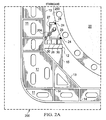
- a support structure such as the longitudinal stringer 12 which is integrated into the ship's hull structure comprised of transverse web frames 11 and longitudinal bulkheads 13 or girders 14, as shown in FIGURES 2A and 2B .
- structures 12, 13 and 14 are preferably continuous structures they can be discontinuous and placed only where necessary.
- FIGURE 5A cylindrical tank 20 is supported internally by ring frame 52.
- transverse saddle 51 is supported by the ship's bottom 57 and side hull 58.
- a hold down bracket 56 is attached to the shell. Hold down bracket 56 presses against the ship's side hull 58 with stopper 55 to prevent floating of the tank. Hold down bracket 56 is on the port and starboard sides of the tank.
- Each saddle carries approximately 50% of the static tank load and this load can nearly double due to ship motions. Under such loads, both the hull and tank will deflect considerably in a complex interaction thereby increasing stresses in both the cargo tank and the support structure. To prevent structural failure, a heavy and complex support structure must be designed using detailed structural analysis.
- tank 20 (shown standing alone in FIGURE 6 ) is effectively resting on a series of support structures longitudinally distributed along the length of the ship's cargo hold as shown expanded in FIGURE 3 .
- pedestals 26 are positioned under the bottom surface of tank support 27 at intervals along each side of the tank parallel to the tank's longitudinal axis.
- the pedestals are advantageously located in locations that correspond to the ship's webframing 11. While the preferred embodiment is that the pedestal are mounted to the tank, an alternate embodiment could position the pedestals along the stringers so that they would mate with the longitudinal support of the tank. In such an embodiment, the stops can be on the tank support.
- the ends of the tank may be hemispherical, Kloeber or other suitable types and need not be the same at both ends.
- the tank diameter may be 25m or more.
- the cylinder length to diameter ratio of the tank is limited primarily by two factors. The first is the deformation of the hull side under hydrostatic and cargo tank loads and its influence on tank deformation. The hull deformation varies as the square of the distance between the cargo hold bulkheads. Therefore a shorter hold will result in considerably less hull deformation.
- the second important length to diameter ratio factor is the limitation of sloshing loads. It is well known that transverse sloshing in a cylindrical tank has little effect on the total tank load. However, sloshing in the longitudinal direction in a cylindrical tank depends on several factors the most significant of which is the length of the tank relative to its diameter. Typically, Type C cylindrical tanks have length to diameter ratios up to 3:1 and utilize swash bulkheads near the ends of the tank attached to the saddle ring frame to reduce sloshing loads. However, with tank diameters above 15m the use of swash bulkheads becomes a technical challenge. By limiting the cylinder length to diameter ratio to under 2:1 the longitudinal sloshing loads may be small enough to eliminate the need for swash bulkheads. For smaller diameter tanks, higher length to diameter ratios could be implemented in conjunction with one or more swash bulkheads.
- the axis of the cylindrical cargo tank is oriented horizontally in the fore and aft longitudinal direction of the ship.
- the tank is supported by pedestals 26 arrayed at intervals on both sides of the tank parallel to and somewhat below the tank's horizontal centerline axis (601 in FIGURE 6 ).
- Pedestals 26 are constructed, in one embodiment, of impregnated laminated wood or other suitable thermal insulating and load bearing material and are fixed to tank lower longitudinal girder 29.
- Vertical supports 27 provide stiffening between lower girder 29 and upper girder 28.
- tank support 602 ( FIGURE 6 ) is welded to the sides of the tank by welds 24 at upper girder 28, lower girder 29 and at vertical stiffener 27.
- the pedestals transfer the weight and vertical loads of the tank and its cargo to the ship's structure by way of longitudinal stringer 12.
- the pedestals transfer the transverse and longitudinal loads of the tank and its cargo to stops 30 and 41 (seen in FIGURES 3 and 4 , respectively) which are fixed to longitudinal stringer 12.
- the stops constrain movement of the pedestal in one direction but allow movement in another direction so as to accommodate the expected thermal expansion and contraction of the tank, the expected deflections of the tank and ship's structure and their interaction on one another.
- the stops incorporate bearing pads which have a surface with a low coefficient of friction such as impregnated wood, polished stainless steel, Teflon, or the like, to facilitate slip between pedestal and stop.
- Girder 29 is designed to carry longitudinal and transverse loads from the tank into the pedestals.
- the lower girders on each side of the tank are located in a horizontal plane the height of which is somewhere between the bottom of tank shell 203 and its horizontal centerline axis.
- the height of the horizontal plane above the bottom is determined by calculating the height at which the lowest overall bending and shear stresses are imposed on the cylindrical tank.
- the height above bottom varies with the geometry of the tank and the forces imposed on it by the ship's motions.
- the height of lower longitudinal girder 29 is generally between 20% and 40% of the tank diameter above the tank bottom.
- a smaller upper longitudinal girder 28 acts to stiffen the tank further and is welded 24 (or otherwise secured) to the outside of tank 20 as shown in FIGURES 2 , 2A , 2B and 6 .
- the upper and lower girders are connected by a series of external vertical stiffeners 27 positioned along the longitudinal axis of the tank at the location of the pedestals.
- the tank internal ring frame 25 at each pedestal acts as the primary structural member for transferring the transverse and vertical tank loads to the pedestals.
- Vertical stiffeners 27 transfer the vertical and transverse loads from ring frame 25 to the pedestals via lower longitudinal girder 29.
- the spacing of the pedestals and ring frames will generally coincide with the ship's transverse webframe spacing.
- the ring frames could be outside the tank in some situations, but as the beam of the ship is generally limited for a given cargo capacity, external ring frames would reduce the tank size and thus the cargo carrying capacity for a ship of a given beam.
- the ship's hull incorporates a longitudinal shelf or stringer 12 at the height of the bottom of the pedestals on each side of the hull.
- a bearing pad may be fitted between the stringer and pedestals.
- the stringers are supported by vertical frames 15 ( FIGURES 2A and 2B ) which distribute the vertical and transverse loads from the tank into the ship's webframes.
- the repetitive nature of the vertical and transverse supports distributes the tank loads fairly evenly into the hull structure. This permits a straight forward and simplified hull structural layout when compared with a Type C tank hull.
- the pedestals are positioned to be approximately level to each other and level with the ship's waterline.
- the ring frames act to carry and distribute loads from the pedestals and permit the design of cargo tanks with diameters much larger than current marine practice.
- the tank is fixed vertically downward and against rotational movement by the weight of the tank resting on pedestals 26 which are, in turn, supported by the ship's structure.
- the tank In case of flooding of the hold, the tank is loosely held from floating up by chains 204 or similar hold down devices located at each pedestal or, if desired, at a minimum of four pedestals, two each side. Chains 204 or similar hold down devices could be attached to the longitudinal stringer 12, bulkhead 13 or similar location to achieve the same preventive purpose.
- transverse stops 30, shown in FIGURE 3 and 4 which are advantageously placed only on one side of the ship (the starboard side in the embodiment shown). This single side placement then allows the tank to expand and contract freely on the unconstrained side.
- FIGURE 3 and 4 show transverse stops 30 at each pedestal 200 along the lateral length of tank 20. If the tank is transversely held only on one ship side then all of the transverse loads are transmitted into that side of the ship's hull. The unsupported tank side is free to move transversely and to accommodate deformation and thermal shrinkage.
- transverse stops on both ship sides along the lateral length of the tank.
- Variations of this transverse stop system may, for example, be the use of transverse stops on both sides of the tank. In such case, the transverse loads can be more or less evenly transmitted into both ship sides.
- the following example variations can be foreseen:
- one set of stops may be arranged for the inboard stop to be in contact with the pedestal in the "cold” tank condition and the outboard stop having contact with the pedestal in the "warm” tank condition, i.e., the stops are spaced so that the tank can expand and contract through thermal cycles without binding in the transverse stops.
- the just mentioned outboard transverse stop may be adjusted after the tank is cold to minimize the gap between pedestal and stop.
- the ideal transverse stop design solution depends on numerous variables and may be different for each ship design depending on hull structure, tank size, liquefied gas density, pressure, etc.
- the longitudinal position is controlled by longitudinal stops 41, FIGURE 4 , which can be placed on the port and starboard side of the tank, as shown.
- the stops act on pedestals fixed to lower girder 29 and sized to accommodate the longitudinal loads in both the forward and aft direction. Only one set of stops port and starboard need be fitted and they are generally located port and starboard at the longitudinal location of tank dome 205 where the fill and discharge pipes are connected to the tank. This stop location allows the tank to expand and contract longitudinally away from the loading pipes (not shown) so as to maintain a fixed position between the tank pipes and the ship's structure.
- the aft end of the tank 32 is closest to the back end of the ship and forward end of the tank 31 is closest to the front end of the ship, as seen in FIGURE 3 .
- Tank dome 205 is a vertical cylindrical cupola mounted at the top of the cylindrical tank usually at the aft end. It acts as a liquid free vapor space for collection of vapors. Cargo tank piping, fill line, pump discharge, vapor line, etc. penetrate the tank through the dome.
- the transverse stops permit movement of the tank in the longitudinal direction.
- the longitudinal stops permit movement only in the transverse direction.
- a gap may exist between the bearing pads mounted on the stops and the pedestals.
- the purpose of the longitudinal and transverse stops is to allow deflection of the tank and ship's hull without imposing undue stresses on one another. At some point the deflection of the tank and/or ship's structure becomes unwanted or unsafe and thus the system is designed to maintain the deflections within the acceptable limits and not require the tank or the ship to be overbuilt.
- a method of installing tanks in cargo ships for the transportation of liquids comprising of: attaching stops to a pair of cargo hold longitudinal stringers at predetermined locations along each stringer, said stops spaced to allow limited movement of pedestals mounted to an underside of longitudinal girders affixed along said cargo tank sides; positioning low friction bearing surfaces with respect to said stops and said longitudinal stringers abutting said pedestals; inserting said cargo tank in the cargo hold such that said pedestals rest on said longitudinal stringers; and attaching hold-down devices between said ship's structure and said tank to prevent said tank from floating upward.
- Said stringers are along port and starboard sides of said hold each running fore and aft, said stringers being relatively level to each other as well as level with said ship's waterline.
- the longitudinal stringers support said cargo tank such that a bottom of said tank is above a bottom of said ship's bottom a distance to minimize stress levels in both said ship and said tank.
- the bearing surfaces are at regular intervals from fore and aft within said hold.
- the stops are located only at an end of said tank where material is loaded into said tank thereby allowing said tank freedom to expand longitudinally away from said material loading end.
Description
- This application claims priority to Provisional Patent Application Serial Number
61/129,639 filed July 9, 2008 U.S. Utility Application No.: 12/484,772 filed June 15, 2009 - This disclosure relates generally to a support system for independent cargo tanks containing liquefied gases and is particularly useful in enabling large diameter cryogenic tanks to be safely installed and operated on liquefied gas carriers.
- It is now common to transport liquefied gases and other materials in tanks positioned within the holds of cargo ships. Particularly, it is well known that liquefied gases, such as LPG, ethylene and LNG, can be transported in tanks permanently attached within the holds of a cargo ship.
- The design and construction of liquefied gas carriers is regulated by the International Maritime Organization (IMO) primarily through application of the International Gas Carrier Code (IGC Code). The IGC Code permits a wide range of cargo containment systems. The cylindrical tank system is the most widely employed containment system for liquefied gas carriers having capacities below approx. 22,000m3. With this system, the cylindrical tanks are supported by two transverse saddles located one near each end of the cylindrical tank. The tank has an internal ring frame at each saddle to help stabilize and distribute the saddle loads into the tank shell. The two saddle system minimizes interaction and resulting stresses between the hull and the tank both of which flex under forces imposed by the ship motions. The diameter and length of such tanks are limited by technical and economic constraints such that the largest single tank known to have been constructed to date has a capacity of about 6,000m3 and the largest ship capacity is believed to be approximately 12,000m3.
- Larger liquefied gas carriers employ either two smaller diameter tanks fitted side by side or a so called bilobe tank. The bilobe tank consists of two parallel, same diameter horizontal cylinders intersecting each other at about 80% of their diameter. An internal longitudinal bulkhead is fitted where the two "lobes" are joined. As with the cylindrical tank, the bilobe tank is supported by two saddles one near each end. Such tanks can be built to diameters of around 15m. The largest such tank known to have been built to date is about 7,500m3 and the largest such liquefied gas carrier employing bilobe tanks has a capacity of around 22,000m3. Currently, there are studies underway for larger carriers in the range of 40,000m3.
- The interaction between tank and hull due to deformation of each is complex and limits the number of support points to two. The diameter of such tanks is practically limited by the density of the cargo, the design pressure of the tank, saddle spacing, fabrication restrictions and economic factors.
- The limitation of two support saddles for each tank results in very large, highly concentrated loads being imposed on the ship's bottom structure. Such "point" loads can exceed 25% of the total loaded ship's displacement (weight in water). These concentrated loads must therefore be distributed throughout the hull structure by way of a complex system of girders and grillage. Such hulls are difficult to fabricate and require more steel than a hull where the cargo load is evenly distributed along the ship's length.
- Both of the above tank types are designed as Type C tanks in accordance with the IGC code. Type C tanks are generally designed to comply with land-based pressure vessel codes such as ASME Div. VIII. However, due to the dynamic loads such tanks are subjected to at sea, the IGC Code requires liquefied gas carrier tanks to be designed to increased design pressures, acceleration forces and safety factors as compared to land-based tanks. Therefore Type C tanks are often designed to pressures and loads considerably higher than they will actually experience during their lifetime. This results in large shell material thickness, high tank weight and excessive cost. Since most liquefied gases are carried at atmospheric pressure, the Type C tank is a disadvantage in weight and cost.
- Spherical tanks are also used to transport liquefied gases, usually liquefied natural gas at -162°C. Such tanks are designed as Type B tanks of the IGC Code. Type B permits the tanks to be designed to pressures, accelerations and fatigue life as may be actually experienced by the ship during its lifetime. Determining the actual expected design loads is a time consuming and expensive process, but such tanks may be designed with lower material thickness and weight compared to a Type C tank. However, spherical tanks are expensive to fabricate and are generally used only in large liquefied natural gas (LNG) carriers. The largest tanks built to date have a diameter of about 43m and a volume of around 40,000m3. In addition to the cost disadvantage, spherical tanks do not utilize the available space in the ship's cargo hold as well as cylindrical tanks and therefore a larger ship must be designed to obtain the same transport capacity.
- Independent prismatic tanks are constructed primarily of flat surfaces which are shaped to utilize the ship's form to the greatest possible extent. These tanks may be either Type B tanks or Type A tanks. Type A tanks require the surrounding ship's hull structure to act as a secondary liquid barrier as a protection should the primary liquefied gas tank leak or fail. The surrounding ship's hull structure must therefore be constructed of expensive, low temperature steel which remains tough and crack resistant at the boiling temperature of the liquefied gas (usually LPG, propane or ammonia). Type B prismatic tanks do not need a fiill secondary barrier and therefore the hull can be built largely of normal ship steel. As with the Type B spherical tank, considerable detailed stress analysis is required to minimize the risk of fatigue or crack propagation. Both tank types have considerable internal support structure similar to the internal hull structure of an oil tanker. Although prismatic tanks have a better volumetric efficiency in the hull than do cylindrical or spherical tanks, they require considerably more material and have limited design pressure.
- In case of flooding of the cargo hold by grounding or collision, the cargo tank must be prevented fi-om floating up and breaking through the upper part of the cargo hold. With conventional Type C tanks this is normally accomplished by four large brackets placed on the upper side of the tank in way of the two ring frames. The floatation load is then transmitted through the brackets to the upper hull sides. With spherical tanks, the tank equator is welded to the ship's structure via a so called skirt and therefore the support structure also holds the tank against floatation. With prismatic tanks the hold down is accomplished by brackets located on the upper sides of the tanks and attached to the sides of the ship in numerous locations.
- There is known tank and ship support arrangement (
US 4345861 ) comprised of two pairs of supporting devices each pair located near opposite tank ends, where each support comprising a tank portion and a hull portion respectively secured to the tank and hull, one of the supports being fixed with respect to linear horizontal movement, another of the supports being movable only transversely of the longitudinal axis of the tank, yet another of the supports being movable parallel to the longitudinal axis of the tank and still another support being movable both parallel to and transversely of the longitudinal axis of the tank; each tank portion of each support being connected with its respective hull portion by means of a spherical joint with thermal insulation between the spherical portions of the joints. - There are disclosed systems and methods for supporting cargo tanks within the hold of a liquefied gas carrier by establishing a series of spaced-apart pedestals along the longitudinal axis of a tank, said pedestals positioned in conjunction with the ship's structural components. These pedestals are of wood or other suitable thermal insulating and load bearing material fixed to the tank below its circumferential diameter along both the starboard and port tank sides. The pedestals rest on structural longitudinal stringers laying port and starboard in the horizontal plane and fixed and supported by the ship's hull structure. Longitudinal and transverse pedestal movement is controlled by stops attached to the stringers at one or more of the pedestals. The stops contact the pedestals via bearing pads which constrain the pedestal in one direction but permit its movement in another. The bearing pads reduce the friction between pedestal and stop thereby allowing free movement in the desired direction.
- In this manner, cylindrical cargo tanks having the weight and material thickness advantages of Type B cargo tanks plus the fabrication advantages of cylindrical Type C tanks can provide better utilization of the cargo space than spherical tanks and reduced material and fabrication cost of prismatic or Type C tanks. Additionally, the spaced-apart pedestals promote even distribution of loads from the tank or tanks into the ship's hull structure thereby enabling a simpler and lighter hull structure while also eliminating excessive hull deflections and reducing sensitivity due to sloshing loads. The design of the pedestals, stops and bearing pads minimize thermal heat transfer and allow for normal cargo tank and hull deflections without adverse affects. Single tank capacities of 15,000m3 or more may be realized with the concepts discussed herein.
- The foregoing has outlined rather broadly the features and technical advantages of the present invention in order that the detailed description of the invention that follows may be better understood. Additional features and advantages of the invention will be described hereinafter which form the subject of the claims of the invention. It should be appreciated by those skilled in the art that the conception and specific embodiment disclosed may be readily utilized as a basis for modifying or designing other structures for carrying out the same purposes of the present invention. It should also be realized by those skilled in the art that such equivalent constructions do not depart from the scope of the invention as set forth in the appended claims. The novel features which are believed to be characteristic of the invention, both as to its organization and method of operation, together with further objects and advantages will be better understood from the following description when considered in connection with the accompanying figures. It is to be expressly understood, however, that each of the figures is provided for the purpose of illustration and description only and is not intended as a definition of the limits of the present invention.
- For a more complete understanding of the present invention, reference is now made to the following descriptions taken in conjunction with the accompanying drawing, in which:
-
FIGURE 1 shows a top view of a liquefied gas carrier having a tank arrangement therein; -
FIGURE 2 shows a cross section of a cargo tank, looking towards the aft, being supported by the system and method described herein; -
FIGURES 2A and2B show expanded views of the starboard and port, respectively supports; -
FIGURES 3 and4 are side and top views, respectively, of a cargo tank being supported by the system and method described herein; -
FIGURES 5A and5B show an example of a cylindrical Type C tank with prior art support arrangement for use in liquefied gas carriers; and -
FIGURE 6 shows one embodiment of a tank having pedestals constructed thereon. -
FIGURE 1 shows a top view of liquefiedgas carrier 10, having cargo tanks 20-1 though 20-4 arranged therein. Note that while the cargo tanks are shown in a straight line displaced along the longitudinal axis of the ship, the concepts discussed herein can be used with any placement of tanks and with any number of tanks. -
FIGURE 2 shows a cross-section oftank 20 being supported by the system and method described herein. In order to facilitate the support system of this invention it is advantageous to add a support structure, such as thelongitudinal stringer 12 which is integrated into the ship's hull structure comprised of transverse web frames 11 andlongitudinal bulkheads 13 orgirders 14, as shown inFIGURES 2A and2B . Note that whilestructures - Before discussing the inventive concepts of this invention it might be helpful to review a prior art support structure as shown with respect to
FIGURES 5A and5B . As shown inFIGURE 5A ,cylindrical tank 20 is supported internally byring frame 52. - In
FIGURE 5B ,transverse saddle 51 is supported by the ship's bottom 57 andside hull 58. Typically, there is wood bearing 54 between the tank and the steel saddle. At eachring frame 52, a hold downbracket 56 is attached to the shell. Hold downbracket 56 presses against the ship'sside hull 58 withstopper 55 to prevent floating of the tank. Hold downbracket 56 is on the port and starboard sides of the tank. There islongitudinal stop 53 at the bottom of one end of the tank. Except for the longitudinal stop, this same structure is repeated at the other end oftank 20 as shown inFIGURE 5A . Each saddle carries approximately 50% of the static tank load and this load can nearly double due to ship motions. Under such loads, both the hull and tank will deflect considerably in a complex interaction thereby increasing stresses in both the cargo tank and the support structure. To prevent structural failure, a heavy and complex support structure must be designed using detailed structural analysis. - Returning now to the concepts of the present invention, as shown in
FIGURES 2 ,2A , and2B , tank 20 (shown standing alone inFIGURE 6 ) is effectively resting on a series of support structures longitudinally distributed along the length of the ship's cargo hold as shown expanded inFIGURE 3 . - In one embodiment, pedestals 26 are positioned under the bottom surface of
tank support 27 at intervals along each side of the tank parallel to the tank's longitudinal axis. The pedestals are advantageously located in locations that correspond to the ship'swebframing 11. While the preferred embodiment is that the pedestal are mounted to the tank, an alternate embodiment could position the pedestals along the stringers so that they would mate with the longitudinal support of the tank. In such an embodiment, the stops can be on the tank support. - The ends of the tank may be hemispherical, Kloeber or other suitable types and need not be the same at both ends. The tank diameter may be 25m or more. The cylinder length to diameter ratio of the tank is limited primarily by two factors. The first is the deformation of the hull side under hydrostatic and cargo tank loads and its influence on tank deformation. The hull deformation varies as the square of the distance between the cargo hold bulkheads. Therefore a shorter hold will result in considerably less hull deformation.
- The second important length to diameter ratio factor is the limitation of sloshing loads. It is well known that transverse sloshing in a cylindrical tank has little effect on the total tank load. However, sloshing in the longitudinal direction in a cylindrical tank depends on several factors the most significant of which is the length of the tank relative to its diameter. Typically, Type C cylindrical tanks have length to diameter ratios up to 3:1 and utilize swash bulkheads near the ends of the tank attached to the saddle ring frame to reduce sloshing loads. However, with tank diameters above 15m the use of swash bulkheads becomes a technical challenge. By limiting the cylinder length to diameter ratio to under 2:1 the longitudinal sloshing loads may be small enough to eliminate the need for swash bulkheads. For smaller diameter tanks, higher length to diameter ratios could be implemented in conjunction with one or more swash bulkheads.
- The axis of the cylindrical cargo tank is oriented horizontally in the fore and aft longitudinal direction of the ship. As discussed, the tank is supported by
pedestals 26 arrayed at intervals on both sides of the tank parallel to and somewhat below the tank's horizontal centerline axis (601 inFIGURE 6 ).Pedestals 26 are constructed, in one embodiment, of impregnated laminated wood or other suitable thermal insulating and load bearing material and are fixed to tank lowerlongitudinal girder 29. Vertical supports 27 provide stiffening betweenlower girder 29 andupper girder 28. In the embodiment shown, tank support 602 (FIGURE 6 ) is welded to the sides of the tank bywelds 24 atupper girder 28,lower girder 29 and atvertical stiffener 27. The pedestals transfer the weight and vertical loads of the tank and its cargo to the ship's structure by way oflongitudinal stringer 12. - Similarly, the pedestals transfer the transverse and longitudinal loads of the tank and its cargo to
stops 30 and 41 (seen inFIGURES 3 and4 , respectively) which are fixed tolongitudinal stringer 12. The stops constrain movement of the pedestal in one direction but allow movement in another direction so as to accommodate the expected thermal expansion and contraction of the tank, the expected deflections of the tank and ship's structure and their interaction on one another. The stops incorporate bearing pads which have a surface with a low coefficient of friction such as impregnated wood, polished stainless steel, Teflon, or the like, to facilitate slip between pedestal and stop. - As discussed, the pedestals are fixed under lower
longitudinal girder 29 which is welded 24 (or otherwise secured) to the outside oftank 20 as shown inFIGURES 2 ,2A ,2B and6 .Girder 29 is designed to carry longitudinal and transverse loads from the tank into the pedestals. The lower girders on each side of the tank are located in a horizontal plane the height of which is somewhere between the bottom oftank shell 203 and its horizontal centerline axis. The height of the horizontal plane above the bottom is determined by calculating the height at which the lowest overall bending and shear stresses are imposed on the cylindrical tank. The height above bottom varies with the geometry of the tank and the forces imposed on it by the ship's motions. The height of lowerlongitudinal girder 29 is generally between 20% and 40% of the tank diameter above the tank bottom. - A smaller upper
longitudinal girder 28 acts to stiffen the tank further and is welded 24 (or otherwise secured) to the outside oftank 20 as shown inFIGURES 2 ,2A ,2B and6 . The upper and lower girders are connected by a series of externalvertical stiffeners 27 positioned along the longitudinal axis of the tank at the location of the pedestals. The tankinternal ring frame 25 at each pedestal acts as the primary structural member for transferring the transverse and vertical tank loads to the pedestals.Vertical stiffeners 27 transfer the vertical and transverse loads fromring frame 25 to the pedestals via lowerlongitudinal girder 29. The spacing of the pedestals and ring frames will generally coincide with the ship's transverse webframe spacing. The ring frames could be outside the tank in some situations, but as the beam of the ship is generally limited for a given cargo capacity, external ring frames would reduce the tank size and thus the cargo carrying capacity for a ship of a given beam. - As discussed, the ship's hull incorporates a longitudinal shelf or
stringer 12 at the height of the bottom of the pedestals on each side of the hull. A bearing pad may be fitted between the stringer and pedestals. The stringers are supported by vertical frames 15 (FIGURES 2A and2B ) which distribute the vertical and transverse loads from the tank into the ship's webframes. The repetitive nature of the vertical and transverse supports distributes the tank loads fairly evenly into the hull structure. This permits a straight forward and simplified hull structural layout when compared with a Type C tank hull. The pedestals are positioned to be approximately level to each other and level with the ship's waterline. Note, the ring frames act to carry and distribute loads from the pedestals and permit the design of cargo tanks with diameters much larger than current marine practice. - The tank is fixed vertically downward and against rotational movement by the weight of the tank resting on
pedestals 26 which are, in turn, supported by the ship's structure. In case of flooding of the hold, the tank is loosely held from floating up bychains 204 or similar hold down devices located at each pedestal or, if desired, at a minimum of four pedestals, two each side.Chains 204 or similar hold down devices could be attached to thelongitudinal stringer 12,bulkhead 13 or similar location to achieve the same preventive purpose. - The transverse position is controlled by
transverse stops 30, shown inFIGURE 3 and4 , which are advantageously placed only on one side of the ship (the starboard side in the embodiment shown). This single side placement then allows the tank to expand and contract freely on the unconstrained side. -
FIGURE 3 and4 show transverse stops 30 at eachpedestal 200 along the lateral length oftank 20. If the tank is transversely held only on one ship side then all of the transverse loads are transmitted into that side of the ship's hull. The unsupported tank side is free to move transversely and to accommodate deformation and thermal shrinkage. - If desired, it is possible to place transverse stops on both ship sides along the lateral length of the tank. Variations of this transverse stop system may, for example, be the use of transverse stops on both sides of the tank. In such case, the transverse loads can be more or less evenly transmitted into both ship sides. The following example variations can be foreseen:
- a) One inboard transverse stop port and one inboard transverse stop starboard per pedestal;
- b) Inboard and outboard stops port and one inboard stop starboard per pedestal; and
- c) Inboard and outboard stops port and inboard and outboard stops starboard per pedestal.
- In case c) one set of stops may be arranged for the inboard stop to be in contact with the pedestal in the "cold" tank condition and the outboard stop having contact with the pedestal in the "warm" tank condition, i.e., the stops are spaced so that the tank can expand and contract through thermal cycles without binding in the transverse stops. In another configuration, the just mentioned outboard transverse stop may be adjusted after the tank is cold to minimize the gap between pedestal and stop.
- The ideal transverse stop design solution depends on numerous variables and may be different for each ship design depending on hull structure, tank size, liquefied gas density, pressure, etc.
- The longitudinal position is controlled by
longitudinal stops 41,FIGURE 4 , which can be placed on the port and starboard side of the tank, as shown. The stops act on pedestals fixed tolower girder 29 and sized to accommodate the longitudinal loads in both the forward and aft direction. Only one set of stops port and starboard need be fitted and they are generally located port and starboard at the longitudinal location oftank dome 205 where the fill and discharge pipes are connected to the tank. This stop location allows the tank to expand and contract longitudinally away from the loading pipes (not shown) so as to maintain a fixed position between the tank pipes and the ship's structure. The aft end of thetank 32 is closest to the back end of the ship and forward end of thetank 31 is closest to the front end of the ship, as seen inFIGURE 3 .Tank dome 205 is a vertical cylindrical cupola mounted at the top of the cylindrical tank usually at the aft end. It acts as a liquid free vapor space for collection of vapors. Cargo tank piping, fill line, pump discharge, vapor line, etc. penetrate the tank through the dome. - The transverse stops permit movement of the tank in the longitudinal direction. The longitudinal stops permit movement only in the transverse direction. A gap may exist between the bearing pads mounted on the stops and the pedestals. The purpose of the longitudinal and transverse stops is to allow deflection of the tank and ship's hull without imposing undue stresses on one another. At some point the deflection of the tank and/or ship's structure becomes unwanted or unsafe and thus the system is designed to maintain the deflections within the acceptable limits and not require the tank or the ship to be overbuilt.
- Although the present invention and its advantages have been described in detail, it should be understood that various changes, substitutions and alterations can be made herein without departing from the scope of the invention as defined by the appended claims. Moreover, the scope of the present application is not intended to be limited to the particular embodiments of the process, machine, manufacture, composition of matter, means, methods and steps described in the specification. As one of ordinary skill in the art will readily appreciate from the disclosure of the present invention, processes, machines, manufacture, compositions of matter, means, methods, or steps, presently existing or later to be developed that perform substantially the same function or achieve substantially the same result as the corresponding embodiments described herein may be utilized according to the present invention. Accordingly, the appended claims are intended to include within their scope such processes, machines, manufacture, compositions of matter, means, methods, or steps.
- There is also proposed a method of installing tanks in cargo ships for the transportation of liquids, said method comprising of: attaching stops to a pair of cargo hold longitudinal stringers at predetermined locations along each stringer, said stops spaced to allow limited movement of pedestals mounted to an underside of longitudinal girders affixed along said cargo tank sides; positioning low friction bearing surfaces with respect to said stops and said longitudinal stringers abutting said pedestals; inserting said cargo tank in the cargo hold such that said pedestals rest on said longitudinal stringers; and attaching hold-down devices between said ship's structure and said tank to prevent said tank from floating upward. Said stringers are along port and starboard sides of said hold each running fore and aft, said stringers being relatively level to each other as well as level with said ship's waterline. The longitudinal stringers support said cargo tank such that a bottom of said tank is above a bottom of said ship's bottom a distance to minimize stress levels in both said ship and said tank. The bearing surfaces are at regular intervals from fore and aft within said hold. The stops are located only at an end of said tank where material is loaded into said tank thereby allowing said tank freedom to expand longitudinally away from said material loading end.
Claims (14)
- A cargo ship having at least one cargo tank (20) positioned in a hold of said ship, said cargo ship comprising:a cargo hold having two ends, two sides, a bottom and a top;transverse structure members (11, 15) and longitudinal structure members (12, 13, 14) within said hold, said transverse members (11, 15) spaced at intervals within said cargo hold;a cylindrical cargo tank (20),longitudinal stringers (12) on each side of said hold fixed to said transverse structural members (11, 15);characterized in that the cargo ship further comprises:at least three pedestal (26) pairs mated to an outside surface of said tank (20) below a circumferential diameter of said tank (20); each said pedestal (26) pair positioned on said tank (20) at a location coincident with one of said transverse structural members (11, 15), where said longitudinal stringers (12) are positioned to support said pedestals (26);transverse stops (30) fixed to said longitudinal stringers (12) so as to constrain movement of said cargo tank pedestals (26) in the transverse direction but not in the longitudinal direction;longitudinal stops (41) at one axial location so as to constrain said pedestals (26) in said longitudinal direction but not said transverse direction, whereinsaid transverse and longitudinal stops (30, 41) are spaced to allow limited movement of said pedestals (26) between said stops (30, 41) in order to maintain cargo tank (20) stresses within safe levels.
- The ship of claim 1, wherein said transverse stops (30) are placed only on one side of the ship.
- The ship of claim 1, wherein said transverse stops (30) are placed at each pedestal (26) along the lateral length of the tank (20).
- The ship of claim 1 wherein said longitudinal stops (41) are located only at an end of said tank (20) where material is loaded into said tank (20) thereby allowing said tank (20) freedom to expand longitudinally away from said material loading end.
- The ship of claim 1 wherein it further comprises a plurality of hold-down devices (204) affixed to transverse structural members (11, 15) so as to keep said tank (20) from floating upward away from said bottom should said cargo hold be flooded.
- The ship of claim 5 wherein said hold-down devices (204) are located at four or more pedestals (26) and prevent said cargo tank (20) from floating up more than a predetermined amount.
- The ship of claim 1 wherein length to diameter of said cargo tank (20) is configured to eliminate harmful effects of sloshing without a need for special provisions within the cargo tank.
- The ship of claim 1 wherein said transverse stops (30), longitudinal stops (41) and longitudinal stringer (12) under the pedestals (26) are abutted by bearing pads having a low coefficient of friction load bearing material.
- The ship of claim 1 wherein said longitudinal stringers (12) stiffen said ship's sides thereby reducing transverse deflection of said cargo hold sides.
- The ship of claim 1 wherein said pedestals (26) are fixed to longitudinal girders (29) attached to the outside shell of said cargo tank (20).
- The ship of claim 1 wherein longitudinal girders (28, 29) are supported by vertical stiffeners (27) located external to said tank (20) above each pedestal (26).
- The ship of claim 1 wherein a ring frame (25) internal to said tank (20) is located at each pedestal (26) so as to carry and distribute loads from each pedestal (26).
- The ship of claim 12 wherein axial spacing of said pedestals (26) and ring frames (25) coincide with the ship's transverse webframe (11) spacing.
- The ship of claim 1 wherein said pedestals (26) are fixed to a longitudinal girder (14) attached to the outside shell (203) of said cargo tank (20) below an axial centerline of said tank (20).
Applications Claiming Priority (3)
| Application Number | Priority Date | Filing Date | Title |
|---|---|---|---|
| US12963908P | 2008-07-09 | 2008-07-09 | |
| US12/484,772 US8245658B2 (en) | 2008-07-09 | 2009-06-15 | Systems and methods for supporting tanks in a cargo ship |
| PCT/US2009/049894 WO2010006023A2 (en) | 2008-07-09 | 2009-07-08 | Systems and methods for supporting tanks in a cargo ship |
Publications (2)
| Publication Number | Publication Date |
|---|---|
| EP2293971A2 EP2293971A2 (en) | 2011-03-16 |
| EP2293971B1 true EP2293971B1 (en) | 2015-08-12 |
Family
ID=41136674
Family Applications (1)
| Application Number | Title | Priority Date | Filing Date |
|---|---|---|---|
| EP09790140.9A Active EP2293971B1 (en) | 2008-07-09 | 2009-07-08 | Systems and methods for supporting tanks in a cargo ship |
Country Status (6)
| Country | Link |
|---|---|
| US (2) | US8245658B2 (en) |
| EP (1) | EP2293971B1 (en) |
| JP (1) | JP2011527656A (en) |
| KR (2) | KR20110014652A (en) |
| CN (1) | CN102066190B (en) |
| WO (1) | WO2010006023A2 (en) |
Families Citing this family (43)
| Publication number | Priority date | Publication date | Assignee | Title |
|---|---|---|---|---|
| US8245658B2 (en) * | 2008-07-09 | 2012-08-21 | John Randolph Holland | Systems and methods for supporting tanks in a cargo ship |
| JP5732347B2 (en) * | 2011-08-12 | 2015-06-10 | ジャパンマリンユナイテッド株式会社 | Tank support structure and floating structure |
| CN102923250A (en) * | 2012-06-27 | 2013-02-13 | 武汉一冶钢结构有限责任公司 | Installation method of shipborne liquid cargo tank saddle seat reinforced by using laminated wood |
| CN102815375A (en) * | 2012-08-26 | 2012-12-12 | 中国葛洲坝集团机械船舶有限公司 | Liquefied oxygen transport ship |
| US20160273709A1 (en) * | 2012-11-13 | 2016-09-22 | Nli Innovation As | Support assembly |
| CN102991892A (en) * | 2012-12-20 | 2013-03-27 | 武汉武船海洋工程船舶设计有限公司 | Hazardous article storage device |
| BR112015025794A2 (en) | 2013-04-23 | 2017-07-25 | Kawasaki Heavy Ind Ltd | Liquefied gas tanker and carrier tank support structure |
| BR112015025930A8 (en) * | 2013-04-23 | 2020-01-14 | Kawasaki Heavy Ind Ltd | double carcass tank structure for use on ships and liquefied gas carrier |
| KR101897851B1 (en) * | 2014-06-18 | 2018-09-13 | 현대중공업 주식회사 | Surpport structure for tank |
| KR20150145069A (en) * | 2014-06-18 | 2015-12-29 | 현대중공업 주식회사 | Support structure for tank |
| KR20150145338A (en) * | 2014-06-18 | 2015-12-30 | 현대중공업 주식회사 | Surpport structure for tank |
| KR102017908B1 (en) * | 2014-06-24 | 2019-10-22 | 한국조선해양 주식회사 | Surpport structure for tank |
| CN105383644B (en) * | 2014-08-19 | 2018-06-29 | 江南造船(集团)有限责任公司 | A kind of independent c-type liquid tank supporting system |
| CN104406767B (en) * | 2014-11-23 | 2017-08-25 | 大连理工大学 | Structure changes formula c-type LNG sloshing pilot systems |
| CN105711752B (en) * | 2014-12-03 | 2018-02-13 | 江南造船(集团)有限责任公司 | The installation method of the vertical bearing insulation of A type independent liquid cargo tank outer side bottom surfaces |
| KR20160087519A (en) | 2015-01-14 | 2016-07-22 | 주식회사 씽크풀 | Authentication method for financial transaction, transaction apparatus, authentication apparatus, and financial transaction system |
| KR20160087518A (en) | 2015-01-14 | 2016-07-22 | 주식회사 씽크풀 | Authentication method for financial transaction, transaction apparatus, authentication apparatus, and financial transaction system |
| KR101584219B1 (en) | 2015-01-27 | 2016-01-11 | 주식회사 씽크풀 | Authentication method, digital system, and authentication system thereof |
| KR20160099766A (en) | 2015-02-12 | 2016-08-23 | 주식회사 씽크풀 | Secure payment method, digital system, and payment system thereof |
| KR20160099767A (en) | 2015-02-12 | 2016-08-23 | 주식회사 씽크풀 | Secure payment method, digital system, and payment system thereof |
| JP6304558B2 (en) * | 2015-02-27 | 2018-04-04 | 三菱重工業株式会社 | Carrier ship |
| CN106143804B (en) * | 2015-03-25 | 2018-05-15 | 江南造船(集团)有限责任公司 | The installation method of the anti-rolling structure in both ends at the top of A types independent liquid cargo tank |
| CN106275282A (en) * | 2015-05-18 | 2017-01-04 | 江南造船(集团)有限责任公司 | C-type flow container supporting structure on liquefied gas carrier deck |
| NL2015003B1 (en) * | 2015-06-19 | 2017-01-24 | Milkways Holding B V | Method to transport liquid milk. |
| WO2017108756A1 (en) * | 2015-12-22 | 2017-06-29 | Shell Internationale Research Maatschappij B.V. | Ship containment system for liquified gases |
| WO2017194818A1 (en) | 2016-05-10 | 2017-11-16 | Wärtsilä Finland Oy | Bilobe or multilobe tank |
| KR102041066B1 (en) * | 2016-05-10 | 2019-11-06 | 바르실라 핀랜드 오이 | Tank array |
| CN106314692A (en) * | 2016-08-29 | 2017-01-11 | 上海斯达瑞船舶海洋工程服务有限公司 | Shaking stopping device of independent type cargo hold and installation method of shaking stopping device |
| CN107672742A (en) * | 2017-09-22 | 2018-02-09 | 江苏江海船舶设备制造有限公司 | A kind of ship air bottle protective cradle |
| CN108116622B (en) * | 2017-11-22 | 2019-12-20 | 上海船舶研究设计院(中国船舶工业集团公司第六0四研究院) | Independent liquid cargo tank limiting assembly and ship |
| CN108082392B (en) * | 2017-12-18 | 2019-11-29 | 湖北海洋工程装备研究院有限公司 | A kind of freighter independence goods tank installation method |
| CN108189972B (en) * | 2017-12-22 | 2020-04-14 | 沪东中华造船(集团)有限公司 | C-shaped tank support used on LNG filling ship and installation method |
| CN109606572B (en) * | 2018-10-31 | 2021-01-19 | 沪东中华造船(集团)有限公司 | B-type fuel cabin structure arrangement applied to container ship |
| DE102018129898B4 (en) * | 2018-11-27 | 2021-02-04 | Airbus Defence and Space GmbH | Device for carrying fuel in an aircraft and spacecraft |
| US10752324B2 (en) * | 2018-12-31 | 2020-08-25 | Gev Technologies Pty. Ltd. | Pipe containment system for ships with spacing guide |
| DE102019115018A1 (en) * | 2019-06-04 | 2020-12-10 | Tge Marine Gas Engineering Gmbh | Tank arrangement |
| CN110822283A (en) * | 2019-09-27 | 2020-02-21 | 广州文冲船厂有限责任公司 | Installation method of vertical LNG storage tank |
| CN114728685A (en) * | 2019-11-29 | 2022-07-08 | 三菱造船株式会社 | Supporting structure of storage tank and ship |
| JP7446928B2 (en) | 2020-06-12 | 2024-03-11 | 三井E&S造船株式会社 | liquefied gas carrier |
| CN112278161B (en) * | 2020-11-03 | 2021-08-10 | 江苏科技大学 | Active pitching device, pitching system and working method of LNG cargo ship |
| CN114148646B (en) * | 2021-12-28 | 2022-11-22 | 西安石油大学 | Oil gas transportation storage and transportation tank convenient to clamping |
| JP2024018231A (en) * | 2022-07-29 | 2024-02-08 | 三菱重工業株式会社 | ship |
| CN115140268B (en) * | 2022-08-11 | 2024-03-26 | 上海外高桥造船有限公司 | Manufacturing and mounting method for double-fuel ship liquid tank saddle split |
Family Cites Families (17)
| Publication number | Priority date | Publication date | Assignee | Title |
|---|---|---|---|---|
| US1634084A (en) * | 1922-10-25 | 1927-06-28 | Vaporackumulator Ab | Support |
| US2706575A (en) * | 1951-03-06 | 1955-04-19 | Air Reduction | Supports for double-walled containers |
| ES406340A1 (en) * | 1972-09-02 | 1973-12-01 | Sener Tecnica Industrial | Ships equipped with pressurized cargo tanks supported on continuous shells |
| US3908574A (en) | 1974-11-22 | 1975-09-30 | Chicago Bridge & Iron Co | Sliding radial key support for LNG ship tanks |
| FR2311990A1 (en) * | 1975-05-22 | 1976-12-17 | Gaz Transport | MEANS OF TRANSPORT WITH SELF-SUPPORTING REVOLUTION TANK, IN PARTICULAR FOR THE TRANSPORT OF A LOW TEMPERATURE FLUID |
| US4086864A (en) | 1976-02-10 | 1978-05-02 | Hitachi Shipbuilding & Engineering Co., Ltd. | Support device for ship-carried independent tank |
| JPS549885A (en) * | 1977-06-24 | 1979-01-25 | Mitsui Eng & Shipbuild Co Ltd | Coastal tanker |
| US4128070A (en) * | 1977-08-17 | 1978-12-05 | Chicago Bridge & Iron Company | Ship tanks with continuous support system |
| NO146351C (en) * | 1978-11-24 | 1982-09-15 | East West Marine | STORAGE ON STORAGE. |
| JPS5695787A (en) | 1979-11-28 | 1981-08-03 | Ogushi Zosen Kk | Device for securing molten substance tank of ship |
| JPH0285600A (en) | 1988-09-22 | 1990-03-27 | Mitsubishi Heavy Ind Ltd | Horizontal and cylindrical tank structure for lng ship |
| JP3517900B2 (en) | 1993-05-28 | 2004-04-12 | 石川島播磨重工業株式会社 | Liquefied gas transport tank support structure |
| FR2711965B3 (en) * | 1993-11-04 | 1996-03-08 | Buffet Denis | Improvement of the spacers of connection of the interior and exterior hulls for Ships with reinforced double hull. |
| JPH0858676A (en) * | 1994-08-26 | 1996-03-05 | Mitsubishi Heavy Ind Ltd | Double hull tanker |
| JP3811866B2 (en) | 1995-11-02 | 2006-08-23 | 株式会社アイ・エイチ・アイ マリンユナイテッド | Support device for liquefied gas tank |
| JPH09142579A (en) * | 1995-11-14 | 1997-06-03 | Fuji Car Mfg Co Ltd | Tank-fixing structure in tank transport vessel |
| US8245658B2 (en) * | 2008-07-09 | 2012-08-21 | John Randolph Holland | Systems and methods for supporting tanks in a cargo ship |
-
2009
- 2009-06-15 US US12/484,772 patent/US8245658B2/en active Active
- 2009-07-08 WO PCT/US2009/049894 patent/WO2010006023A2/en active Application Filing
- 2009-07-08 CN CN200980123270.9A patent/CN102066190B/en active Active
- 2009-07-08 EP EP09790140.9A patent/EP2293971B1/en active Active
- 2009-07-08 KR KR1020107028422A patent/KR20110014652A/en active Search and Examination
- 2009-07-08 KR KR1020137025439A patent/KR20130111649A/en not_active Application Discontinuation
- 2009-07-08 JP JP2011517557A patent/JP2011527656A/en active Pending
-
2012
- 2012-06-21 US US13/529,711 patent/US20120255481A1/en not_active Abandoned
Also Published As
| Publication number | Publication date |
|---|---|
| CN102066190B (en) | 2015-01-14 |
| US8245658B2 (en) | 2012-08-21 |
| WO2010006023A2 (en) | 2010-01-14 |
| US20100012014A1 (en) | 2010-01-21 |
| WO2010006023A3 (en) | 2010-09-30 |
| KR20110014652A (en) | 2011-02-11 |
| US20120255481A1 (en) | 2012-10-11 |
| JP2011527656A (en) | 2011-11-04 |
| CN102066190A (en) | 2011-05-18 |
| KR20130111649A (en) | 2013-10-10 |
| EP2293971A2 (en) | 2011-03-16 |
Similar Documents
| Publication | Publication Date | Title |
|---|---|---|
| EP2293971B1 (en) | Systems and methods for supporting tanks in a cargo ship | |
| EP3254948B1 (en) | Hydrocarbon processing vessel and method | |
| KR102490542B1 (en) | Closed and insulated tank with loading/unloading tower | |
| US3680323A (en) | Tanker for liquified and/or compressed gas | |
| US6786166B1 (en) | Liquefied gas storage barge with concrete floating structure | |
| JP6121900B2 (en) | Supporting tanks in the ship | |
| NO331660B1 (en) | Device for liquid production of LNG and method for converting an LNG ship to such device | |
| US8091494B2 (en) | Liquefied gas tank with a central hub in the bottom structure | |
| EP2247888B1 (en) | A liquefied gas tank with a central hub in the bottom structure | |
| CA2909228A1 (en) | Lng ship | |
| US11821587B2 (en) | Sealed and thermally insulating tank | |
| KR20210031950A (en) | Fluid-storage facility | |
| AU2008332002B2 (en) | A liquefied gas tank with a central hub in the bottom structure | |
| KR102327630B1 (en) | liquefied gas tank and ship having the same | |
| Bergan et al. | A scalable and prismatic pressure vessel for transport and storage of natural gas | |
| CN116113789A (en) | Guiding structure for loading/unloading a tower for storing and/or transporting tanks of liquefied gas |
Legal Events
| Date | Code | Title | Description |
|---|---|---|---|
| PUAI | Public reference made under article 153(3) epc to a published international application that has entered the european phase |
Free format text: ORIGINAL CODE: 0009012 |
|
| 17P | Request for examination filed |
Effective date: 20101220 |
|
| AK | Designated contracting states |
Kind code of ref document: A2 Designated state(s): AT BE BG CH CY CZ DE DK EE ES FI FR GB GR HR HU IE IS IT LI LT LU LV MC MK MT NL NO PL PT RO SE SI SK SM TR |
|
| AX | Request for extension of the european patent |
Extension state: AL BA RS |
|
| DAX | Request for extension of the european patent (deleted) | ||
| 17Q | First examination report despatched |
Effective date: 20131122 |
|
| REG | Reference to a national code |
Ref country code: DE Ref legal event code: R079 Ref document number: 602009032891 Country of ref document: DE Free format text: PREVIOUS MAIN CLASS: B63B0003700000 Ipc: B63B0025140000 |
|
| RIC1 | Information provided on ipc code assigned before grant |
Ipc: B63B 25/12 20060101ALI20150121BHEP Ipc: B63B 17/00 20060101ALI20150121BHEP Ipc: B63B 3/70 20060101ALI20150121BHEP Ipc: B63B 25/14 20060101AFI20150121BHEP Ipc: B63B 25/16 20060101ALI20150121BHEP |
|
| GRAP | Despatch of communication of intention to grant a patent |
Free format text: ORIGINAL CODE: EPIDOSNIGR1 |
|
| INTG | Intention to grant announced |
Effective date: 20150324 |
|
| GRAS | Grant fee paid |
Free format text: ORIGINAL CODE: EPIDOSNIGR3 |
|
| GRAA | (expected) grant |
Free format text: ORIGINAL CODE: 0009210 |
|
| AK | Designated contracting states |
Kind code of ref document: B1 Designated state(s): AT BE BG CH CY CZ DE DK EE ES FI FR GB GR HR HU IE IS IT LI LT LU LV MC MK MT NL NO PL PT RO SE SI SK SM TR |
|
| REG | Reference to a national code |
Ref country code: GB Ref legal event code: FG4D |
|
| REG | Reference to a national code |
Ref country code: CH Ref legal event code: EP |
|
| REG | Reference to a national code |
Ref country code: AT Ref legal event code: REF Ref document number: 741893 Country of ref document: AT Kind code of ref document: T Effective date: 20150815 |
|
| REG | Reference to a national code |
Ref country code: IE Ref legal event code: FG4D |
|
| REG | Reference to a national code |
Ref country code: DE Ref legal event code: R096 Ref document number: 602009032891 Country of ref document: DE |
|
| REG | Reference to a national code |
Ref country code: LT Ref legal event code: MG4D |
|
| REG | Reference to a national code |
Ref country code: AT Ref legal event code: MK05 Ref document number: 741893 Country of ref document: AT Kind code of ref document: T Effective date: 20150812 |
|
| REG | Reference to a national code |
Ref country code: NL Ref legal event code: MP Effective date: 20150812 |
|
| PG25 | Lapsed in a contracting state [announced via postgrant information from national office to epo] |
Ref country code: GR Free format text: LAPSE BECAUSE OF FAILURE TO SUBMIT A TRANSLATION OF THE DESCRIPTION OR TO PAY THE FEE WITHIN THE PRESCRIBED TIME-LIMIT Effective date: 20151113 Ref country code: LT Free format text: LAPSE BECAUSE OF FAILURE TO SUBMIT A TRANSLATION OF THE DESCRIPTION OR TO PAY THE FEE WITHIN THE PRESCRIBED TIME-LIMIT Effective date: 20150812 Ref country code: NO Free format text: LAPSE BECAUSE OF FAILURE TO SUBMIT A TRANSLATION OF THE DESCRIPTION OR TO PAY THE FEE WITHIN THE PRESCRIBED TIME-LIMIT Effective date: 20151112 Ref country code: LV Free format text: LAPSE BECAUSE OF FAILURE TO SUBMIT A TRANSLATION OF THE DESCRIPTION OR TO PAY THE FEE WITHIN THE PRESCRIBED TIME-LIMIT Effective date: 20150812 Ref country code: FI Free format text: LAPSE BECAUSE OF FAILURE TO SUBMIT A TRANSLATION OF THE DESCRIPTION OR TO PAY THE FEE WITHIN THE PRESCRIBED TIME-LIMIT Effective date: 20150812 |
|
| PG25 | Lapsed in a contracting state [announced via postgrant information from national office to epo] |
Ref country code: PT Free format text: LAPSE BECAUSE OF FAILURE TO SUBMIT A TRANSLATION OF THE DESCRIPTION OR TO PAY THE FEE WITHIN THE PRESCRIBED TIME-LIMIT Effective date: 20151214 Ref country code: SE Free format text: LAPSE BECAUSE OF FAILURE TO SUBMIT A TRANSLATION OF THE DESCRIPTION OR TO PAY THE FEE WITHIN THE PRESCRIBED TIME-LIMIT Effective date: 20150812 Ref country code: IS Free format text: LAPSE BECAUSE OF FAILURE TO SUBMIT A TRANSLATION OF THE DESCRIPTION OR TO PAY THE FEE WITHIN THE PRESCRIBED TIME-LIMIT Effective date: 20151212 Ref country code: AT Free format text: LAPSE BECAUSE OF FAILURE TO SUBMIT A TRANSLATION OF THE DESCRIPTION OR TO PAY THE FEE WITHIN THE PRESCRIBED TIME-LIMIT Effective date: 20150812 Ref country code: PL Free format text: LAPSE BECAUSE OF FAILURE TO SUBMIT A TRANSLATION OF THE DESCRIPTION OR TO PAY THE FEE WITHIN THE PRESCRIBED TIME-LIMIT Effective date: 20150812 Ref country code: HR Free format text: LAPSE BECAUSE OF FAILURE TO SUBMIT A TRANSLATION OF THE DESCRIPTION OR TO PAY THE FEE WITHIN THE PRESCRIBED TIME-LIMIT Effective date: 20150812 Ref country code: ES Free format text: LAPSE BECAUSE OF FAILURE TO SUBMIT A TRANSLATION OF THE DESCRIPTION OR TO PAY THE FEE WITHIN THE PRESCRIBED TIME-LIMIT Effective date: 20150812 |
|
| PG25 | Lapsed in a contracting state [announced via postgrant information from national office to epo] |
Ref country code: NL Free format text: LAPSE BECAUSE OF FAILURE TO SUBMIT A TRANSLATION OF THE DESCRIPTION OR TO PAY THE FEE WITHIN THE PRESCRIBED TIME-LIMIT Effective date: 20150812 |
|
| PG25 | Lapsed in a contracting state [announced via postgrant information from national office to epo] |
Ref country code: DK Free format text: LAPSE BECAUSE OF FAILURE TO SUBMIT A TRANSLATION OF THE DESCRIPTION OR TO PAY THE FEE WITHIN THE PRESCRIBED TIME-LIMIT Effective date: 20150812 Ref country code: SK Free format text: LAPSE BECAUSE OF FAILURE TO SUBMIT A TRANSLATION OF THE DESCRIPTION OR TO PAY THE FEE WITHIN THE PRESCRIBED TIME-LIMIT Effective date: 20150812 Ref country code: IT Free format text: LAPSE BECAUSE OF FAILURE TO SUBMIT A TRANSLATION OF THE DESCRIPTION OR TO PAY THE FEE WITHIN THE PRESCRIBED TIME-LIMIT Effective date: 20150812 Ref country code: EE Free format text: LAPSE BECAUSE OF FAILURE TO SUBMIT A TRANSLATION OF THE DESCRIPTION OR TO PAY THE FEE WITHIN THE PRESCRIBED TIME-LIMIT Effective date: 20150812 Ref country code: CZ Free format text: LAPSE BECAUSE OF FAILURE TO SUBMIT A TRANSLATION OF THE DESCRIPTION OR TO PAY THE FEE WITHIN THE PRESCRIBED TIME-LIMIT Effective date: 20150812 |
|
| REG | Reference to a national code |
Ref country code: DE Ref legal event code: R097 Ref document number: 602009032891 Country of ref document: DE |
|
| PG25 | Lapsed in a contracting state [announced via postgrant information from national office to epo] |
Ref country code: RO Free format text: LAPSE BECAUSE OF FAILURE TO SUBMIT A TRANSLATION OF THE DESCRIPTION OR TO PAY THE FEE WITHIN THE PRESCRIBED TIME-LIMIT Effective date: 20150812 |
|
| PLBE | No opposition filed within time limit |
Free format text: ORIGINAL CODE: 0009261 |
|
| STAA | Information on the status of an ep patent application or granted ep patent |
Free format text: STATUS: NO OPPOSITION FILED WITHIN TIME LIMIT |
|
| REG | Reference to a national code |
Ref country code: FR Ref legal event code: PLFP Year of fee payment: 8 |
|
| 26N | No opposition filed |
Effective date: 20160513 |
|
| PG25 | Lapsed in a contracting state [announced via postgrant information from national office to epo] |
Ref country code: SI Free format text: LAPSE BECAUSE OF FAILURE TO SUBMIT A TRANSLATION OF THE DESCRIPTION OR TO PAY THE FEE WITHIN THE PRESCRIBED TIME-LIMIT Effective date: 20150812 |
|
| PG25 | Lapsed in a contracting state [announced via postgrant information from national office to epo] |
Ref country code: BE Free format text: LAPSE BECAUSE OF FAILURE TO SUBMIT A TRANSLATION OF THE DESCRIPTION OR TO PAY THE FEE WITHIN THE PRESCRIBED TIME-LIMIT Effective date: 20150812 |
|
| REG | Reference to a national code |
Ref country code: CH Ref legal event code: PL |
|
| PG25 | Lapsed in a contracting state [announced via postgrant information from national office to epo] |
Ref country code: MC Free format text: LAPSE BECAUSE OF FAILURE TO SUBMIT A TRANSLATION OF THE DESCRIPTION OR TO PAY THE FEE WITHIN THE PRESCRIBED TIME-LIMIT Effective date: 20150812 |
|
| PG25 | Lapsed in a contracting state [announced via postgrant information from national office to epo] |
Ref country code: CH Free format text: LAPSE BECAUSE OF NON-PAYMENT OF DUE FEES Effective date: 20160731 Ref country code: LI Free format text: LAPSE BECAUSE OF NON-PAYMENT OF DUE FEES Effective date: 20160731 |
|
| REG | Reference to a national code |
Ref country code: IE Ref legal event code: MM4A |
|
| REG | Reference to a national code |
Ref country code: FR Ref legal event code: PLFP Year of fee payment: 9 |
|
| PG25 | Lapsed in a contracting state [announced via postgrant information from national office to epo] |
Ref country code: IE Free format text: LAPSE BECAUSE OF NON-PAYMENT OF DUE FEES Effective date: 20160708 |
|
| PG25 | Lapsed in a contracting state [announced via postgrant information from national office to epo] |
Ref country code: LU Free format text: LAPSE BECAUSE OF NON-PAYMENT OF DUE FEES Effective date: 20160708 |
|
| REG | Reference to a national code |
Ref country code: FR Ref legal event code: PLFP Year of fee payment: 10 |
|
| PG25 | Lapsed in a contracting state [announced via postgrant information from national office to epo] |
Ref country code: HU Free format text: LAPSE BECAUSE OF FAILURE TO SUBMIT A TRANSLATION OF THE DESCRIPTION OR TO PAY THE FEE WITHIN THE PRESCRIBED TIME-LIMIT; INVALID AB INITIO Effective date: 20090708 Ref country code: SM Free format text: LAPSE BECAUSE OF FAILURE TO SUBMIT A TRANSLATION OF THE DESCRIPTION OR TO PAY THE FEE WITHIN THE PRESCRIBED TIME-LIMIT Effective date: 20150812 Ref country code: CY Free format text: LAPSE BECAUSE OF FAILURE TO SUBMIT A TRANSLATION OF THE DESCRIPTION OR TO PAY THE FEE WITHIN THE PRESCRIBED TIME-LIMIT Effective date: 20150812 |
|
| PG25 | Lapsed in a contracting state [announced via postgrant information from national office to epo] |
Ref country code: TR Free format text: LAPSE BECAUSE OF FAILURE TO SUBMIT A TRANSLATION OF THE DESCRIPTION OR TO PAY THE FEE WITHIN THE PRESCRIBED TIME-LIMIT Effective date: 20150812 Ref country code: MT Free format text: LAPSE BECAUSE OF NON-PAYMENT OF DUE FEES Effective date: 20160731 Ref country code: MK Free format text: LAPSE BECAUSE OF FAILURE TO SUBMIT A TRANSLATION OF THE DESCRIPTION OR TO PAY THE FEE WITHIN THE PRESCRIBED TIME-LIMIT Effective date: 20150812 |
|
| PG25 | Lapsed in a contracting state [announced via postgrant information from national office to epo] |
Ref country code: BG Free format text: LAPSE BECAUSE OF FAILURE TO SUBMIT A TRANSLATION OF THE DESCRIPTION OR TO PAY THE FEE WITHIN THE PRESCRIBED TIME-LIMIT Effective date: 20150812 |
|
| REG | Reference to a national code |
Ref country code: DE Ref legal event code: R081 Ref document number: 602009032891 Country of ref document: DE Owner name: SSRC TECHNOLOGIES GMBH, DE Free format text: FORMER OWNER: HOLLAND, JOHN RANDOLPH, 28790 SCHWANEWEDE, DE Ref country code: DE Ref legal event code: R081 Ref document number: 602009032891 Country of ref document: DE Owner name: SSRC TECHNOLOGIES AS, NO Free format text: FORMER OWNER: HOLLAND, JOHN RANDOLPH, 28790 SCHWANEWEDE, DE |
|
| REG | Reference to a national code |
Ref country code: GB Ref legal event code: 732E Free format text: REGISTERED BETWEEN 20191017 AND 20191023 |
|
| REG | Reference to a national code |
Ref country code: DE Ref legal event code: R081 Ref document number: 602009032891 Country of ref document: DE Owner name: SSRC TECHNOLOGIES AS, NO Free format text: FORMER OWNER: SSRC TECHNOLOGIES GMBH, 28790 SCHWANEWEDE, DE |
|
| REG | Reference to a national code |
Ref country code: GB Ref legal event code: 732E Free format text: REGISTERED BETWEEN 20210624 AND 20210630 |
|
| PGFP | Annual fee paid to national office [announced via postgrant information from national office to epo] |
Ref country code: GB Payment date: 20220627 Year of fee payment: 14 |
|
| PGFP | Annual fee paid to national office [announced via postgrant information from national office to epo] |
Ref country code: FR Payment date: 20220627 Year of fee payment: 14 |
|
| PGFP | Annual fee paid to national office [announced via postgrant information from national office to epo] |
Ref country code: DE Payment date: 20220628 Year of fee payment: 14 |
|
| REG | Reference to a national code |
Ref country code: DE Ref legal event code: R119 Ref document number: 602009032891 Country of ref document: DE |
|
| GBPC | Gb: european patent ceased through non-payment of renewal fee |
Effective date: 20230708 |