EP2293597B1 - Multidirektionale Schallemissionsmittel und multidirektionales Schallemissionssystem - Google Patents
Multidirektionale Schallemissionsmittel und multidirektionales Schallemissionssystem Download PDFInfo
- Publication number
- EP2293597B1 EP2293597B1 EP10158882.0A EP10158882A EP2293597B1 EP 2293597 B1 EP2293597 B1 EP 2293597B1 EP 10158882 A EP10158882 A EP 10158882A EP 2293597 B1 EP2293597 B1 EP 2293597B1
- Authority
- EP
- European Patent Office
- Prior art keywords
- sound
- sound emission
- conducting elements
- directional
- sound conducting
- Prior art date
- Legal status (The legal status is an assumption and is not a legal conclusion. Google has not performed a legal analysis and makes no representation as to the accuracy of the status listed.)
- Not-in-force
Links
Images


Classifications
-
- H—ELECTRICITY
- H04—ELECTRIC COMMUNICATION TECHNIQUE
- H04R—LOUDSPEAKERS, MICROPHONES, GRAMOPHONE PICK-UPS OR LIKE ACOUSTIC ELECTROMECHANICAL TRANSDUCERS; DEAF-AID SETS; PUBLIC ADDRESS SYSTEMS
- H04R5/00—Stereophonic arrangements
- H04R5/02—Spatial or constructional arrangements of loudspeakers
-
- H—ELECTRICITY
- H04—ELECTRIC COMMUNICATION TECHNIQUE
- H04R—LOUDSPEAKERS, MICROPHONES, GRAMOPHONE PICK-UPS OR LIKE ACOUSTIC ELECTROMECHANICAL TRANSDUCERS; DEAF-AID SETS; PUBLIC ADDRESS SYSTEMS
- H04R1/00—Details of transducers, loudspeakers or microphones
- H04R1/20—Arrangements for obtaining desired frequency or directional characteristics
- H04R1/32—Arrangements for obtaining desired frequency or directional characteristics for obtaining desired directional characteristic only
- H04R1/34—Arrangements for obtaining desired frequency or directional characteristics for obtaining desired directional characteristic only by using a single transducer with sound reflecting, diffracting, directing or guiding means
- H04R1/345—Arrangements for obtaining desired frequency or directional characteristics for obtaining desired directional characteristic only by using a single transducer with sound reflecting, diffracting, directing or guiding means for loudspeakers
-
- H—ELECTRICITY
- H04—ELECTRIC COMMUNICATION TECHNIQUE
- H04R—LOUDSPEAKERS, MICROPHONES, GRAMOPHONE PICK-UPS OR LIKE ACOUSTIC ELECTROMECHANICAL TRANSDUCERS; DEAF-AID SETS; PUBLIC ADDRESS SYSTEMS
- H04R2205/00—Details of stereophonic arrangements covered by H04R5/00 but not provided for in any of its subgroups
- H04R2205/022—Plurality of transducers corresponding to a plurality of sound channels in each earpiece of headphones or in a single enclosure
-
- H—ELECTRICITY
- H04—ELECTRIC COMMUNICATION TECHNIQUE
- H04R—LOUDSPEAKERS, MICROPHONES, GRAMOPHONE PICK-UPS OR LIKE ACOUSTIC ELECTROMECHANICAL TRANSDUCERS; DEAF-AID SETS; PUBLIC ADDRESS SYSTEMS
- H04R2205/00—Details of stereophonic arrangements covered by H04R5/00 but not provided for in any of its subgroups
- H04R2205/024—Positioning of loudspeaker enclosures for spatial sound reproduction
Definitions
- the present invention relates to speaker devices and, more particularly, to a multi-directional sound emission means and a multi-directional sound emission system, which can generate surround sound effect.
- a traditional speaker system generally can produce a stereophonic effect with a plurality of audio channels by setting a set of stereophonic speaker assembly.
- a typical stereophonic speaker assembly includes a pair of primary loudspeakers and a pair of secondary separate loudspeakers to form four sound emission fields.
- a speaker assembly is lack of a sense of three-dimensional depth.
- Stereophonic effect can only be enjoyed at a middle location between the two loudspeakers. If the listener is adjacent to one loudspeaker but is far from the other loudspeaker, the stereophonic effect is significantly decreased. Further, in this structure, the speaker assembly occupies a large space in a room and it is inconvenient to carry and move away.
- Some stereophonic speaker assemblies can achieve surround sound effect by a surround sound system.
- the surround sound system simulates a desired three-dimensional environment by directing sound to the listener from various orientations, including front, side, back, floor and ceiling propagation.
- Modem surround sound systems capitalize on diverse speakers to generate both stereophonic and multi-audio channel output, as well as synchronized shifting of isolated sounds to individual speakers disposed around the listener.
- a speaker assembly is equipped with a speaker array constituting a 5.1ch surround sound system, e.g., a front left audio channel, a front right audio channel, a center audio channel, a rear left audio channel, a rear right audio channel, and a subwoofer LFE(Low Frequency Effects)ch.
- This digital speaker assembly typically includes a speaker array apparatus.
- the speaker array apparatus includes a plurality of speaker units from which audio is outputted and reflected with directivity against a predetermined wall surface or a reflection plate so as to form a virtual speaker.
- Each of the plurality of speaker units is independently driven so that an audio beam generated according to the input audio signal by a digital signal processor is emitted to a predetermined focal point position in a space.
- WO2005004531A1 discloses a stereo loudspeaker having the first sound source for reproducing the signal of the first stereo channel and the second sound source for reproducing the signal of the second stereo channel.
- the stereo loudspeaker further includes the sound guide and in it opposed to each other the first part and the second part placed in a way that the sound produced by the first sound source is directed to the first part and the sound produced by the second sound source is directed to the second part.
- the first part and the second part are essentially flat and they both determine a plance, the planes being essentially parallel.
- the first part has a number of acoustic channels extending radially outwards, the channels curving identically from their radial direction in the plane defined by the first part.
- the second part has a number of acoustic channels extending radially outwards, the channels curving from their radial direction in the plane defined by the second part in an opposite way from the acoustic channels of the first part.
- US2096192A discloses a combination of a baffle having a substantially central aperture, a cover member disposed above and covering said aperture and having its edge spaced from said baffle, means fastening said cover member and baffle together, a loud speaker disposed in said cover member and having a concave conical diaphragm disposed at and directed toward said opening in said baffle, means connecting the edge of said speaker unit with said baffle, a flange extending upwardly from said baffle around said speaker unit and spaced inwardly from said cover member, a conical deflector of substantially the same shape as the conical diaphragm disposed on the same axis as and spaced from and having its apex directed toward said diaphragm, a second baffle extending from the edge of said first named baffle, means for supporting said baffle and said deflector in position, and supporting means fastened to said cover member.
- a sound emission means according to claim 1 are disclosed.
- a multi-directional sound emission system comprises a speaker body and sound emission devices coupled to both ends of the speaker body.
- the sound emission devices each include the sound emission means according to claims 1-9 configured for directionally emitting sound towards multiple directions.
- the present multi-directional sound emission means and system both have a compact structure and a reduced cost, and is easy to assemble.
- the sound emission means 16 includes a base 162, a loudspeaker 164 disposed on the base 162, and a plurality of hollow mechanical sound conducting elements 18.
- the loudspeaker 164 has an opening 166 where the sound is emitted.
- Each hollow mechanical sound conducting element 18 has an inner opening end 182 and an exterior opening end 180 opposite to the inner opening end 182.
- the exterior opening ends 180 of the sound conducting elements 18 are directed towards desired multiple directions, respectively.
- the inner opening ends 182 of the mechanical sound conducting elements 18 are in sound communication with the opening 166 of the loudspeaker 164. In this way, sound from the loudspeaker 164 is emitted along the desired multiple directions through the sound conducting elements 18.
- the sound conducting elements 18 are sound conducting conduits 18.
- the sound conducting conduits 18 could be a hollow pipe with the inner opening end 182 and the exterior opening end 180 opposite to the inner opening end 182, as shown in FIGS. 1 and 2 .
- a sphere mask 165 is overlaid at the opening 166. The inner opening end 182 of each sound conducting conduit 18 is penetrated through the sphere mask 165 to be in sound communication with the loudspeaker 164 and the exterior opening end 180 is directed to outside.
- sound communication means that the sound from the opening 166 is propagated outwardly along the sound conducting elements 18.
- the opening 166 is in direct (e.g., gas) communication with the sound conducting conduits 18.
- the opening 166 is shielded with a vibrating membrane or a mesh mask. In this case, although the opening 166 is not in direct communication with the sound conducting conduits 18, the sound is able to be transferred to the sound conducting conduits 18, e.g., by means of vibration, and then spread out through the sound conducting conduits 18.
- the sound conducting conduits 18 are protruded out of the base 162 according to predetermined exit angles or position distributions, such as for example, but not limited to, in a radially divergent form as shown in FIG. 1 .
- the plurality of sound conducting conduits 18 is in a spherical divergent form.
- the sound conducting conduits 18 extend along imaginary normal directions which are converged to a spherical center of the sphere mask 165.
- the spherical center of the sphere mask 165 is preferably a center of the opening 166.
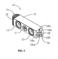
- the sphere mask 165 could be a partial sphere or a quarter sphere (as shown in FIG. 3 ).
- the exterior opening ends 180 of the sound conducting conduits 18 are appeared as a spherical profile or a curved profile.
- FIG. 3 illustrates a multi-directional sound emission system 10 having the above multi-directional sound emission means 16.
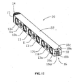
- the multi-directional sound emission system 10 further comprises a speaker body 12 and sound emission devices 14 coupled to both ends of the speaker body 12.
- the sound emission devices 14 each include the sound emission means 16 described above with the base 162, the loudspeaker 164 and the plurality of hollow mechanical sound conducting elements 18.
- Each hollow mechanical sound conducting element 18 has the inner opening end 182 and the exterior opening end 180 opposite to the inner opening end 182.
- the exterior opening ends 180 of the sound conducting elements 18 are directed towards desired multiple directions, respectively.
- the sound emission means 16 is configured for receiving sound signals from the speaker body 12 and emitting sound along the desired multiple directions through the sound conducting elements 18. For example, the sound signals from the speaker body 12 are transmitted to the loudspeaker 164, and then directed towards the desired multiple directions through the sound conducting elements 18.
- the speaker body 12 and the sound emission devices 14 is integrated or configured as a whole.
- the multi-directional sound emission system 10 is substantially a three-audio channel sound system.
- the speaker body 12 is provided with a sound source device (not shown) for receiving sound input from external apparatus, e.g., a TV set or a DVD player.
- the speaker body 12 includes an audio middle frequency controller 11 substantially disposed at a center section thereof and two speakers 13 coupled to both ends of the controller 11.
- the middle frequency controller 11 and the two speakers 13 cooperatively constitute a center audio channel.
- the sound emission devices 14 at both ends of the speaker body 12 respectively serve as a left surround audio channel and a right surround audio channel (as an example, the positions herein is referred to as the positions shown in the figures).
- the sound emission devices 14 coupled to the right side of the speaker body 12 includes a plurality of hollow mechanical sound conducting elements 18 radially distributed in a three-dimensional direction, thereby emitting sound along various directions in three-dimension.
- each sound emission device 14 further includes a porous cover 15 configured for protecting the sound conducting elements 18 therein from being injured and allowing sound to pass through.
- the porous cover 15 is a metal or plastic mesh enclosure.
- the right porous cover 15 protecting the sound conducting elements 18 is removed away to show inner structure of the right sound emission device 14, while the left porous cover 15 is kept to cover the left sound conducting elements 18 therein.
- the sound conducting elements 18 include a group of front sound conducting conduits 18a, a group of lateral sound conducting conduits 18b, a group of upper sound conducting conduits 18c, and a group of lower sound conducting conduits 18d.
- Each of the four groups of sound conducting conduits 18a includes at least one sound conducting conduit.
- the front sound conducting conduits 18a are directed to direct or biased front of the speaker body 12, for propagating sound along a forward direction.
- the openings of the front sound conducting conduits 18a face towards the direct or biased front of the speaker body 12.
- the front sound conducting conduits 18a on the right produce anterolateral sound wave and serve as a front right audio channel.
- the lateral sound conducting conduits 18b on the right are directed to direct or biased lateral of the speaker body 12, for propagating sound along a lateral direction.
- the openings of the lateral sound conducting conduits 18b face towards the direct or biased lateral of the speaker body 12.
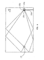
- FIG. 5 when the sound emission system 10 is placed in a room, most of the sound waves from the lateral sound conducting conduits 18b are reflected towards a listening location 19 by side walls. Some sound waves from the lateral sound conducting conduits 18b are reflected twice, e.g., firstly towards a rear wall by the side walls and then towards the listening location 19 by the rear wall.
- the upper sound conducting conduits 18c are directed to direct or biased above of the speaker body 12, for propagating sound along an upward direction.
- the openings of the upper sound conducting conduits 18c face towards the direct or biased above of the speaker body 12.
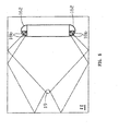
- FIG. 4 when the sound emission system 10 is placed in a room, most of the sound waves from the upper sound conducting conduits 18c are reflected towards a listening location 19 by a ceiling. Some sound waves from the upper sound conducting conduits 18c are reflected twice, e.g., firstly towards the rear wall by the ceiling and then towards the listening location 19 by the rear wall.
- the lower sound conducting conduits 18d are directed to direct or biased below of the speaker body 12, for propagating sound along a downward direction.
- the openings of the lower sound conducting conduits 18d face towards the direct or biased below of the speaker body 12.
- FIG. 4 when the sound emission system 10 is placed in a room, most of the sound waves from the lower sound conducting conduits 18d are reflected towards a listening location 19 by a floor. Some sound waves from the lower sound conducting conduits 18d are reflected twice, e.g., firstly towards the floor by the floor and then towards the listening location 19 by the rear wall.
- the sound emission means 16 on the right serves as a right surround audio channel in relation to the listening location 19 by means of the four groups of sound conducting conduits 18a, 18b, 18c, 18d.
- the left sound emission means 16 has the same structure to the right sound emission means 16 and thus serves as a left surround audio channel in relation to the listening location 19 by means of similar four groups of sound conducting conduits on the left.
- the length of the sound conducting conduits 18 may be uniform or different from each other.
- the sizes of the openings of the sound conducting conduits 18 may be uniform or different from each other.
- the sound conducting conduits 18 are in a tubular shape.
- the tubular sound conducting conduits 18 have narrow openings (e.g., narrow opening end 180 relative to the opening end 182) and are elongated, and thus emit acute sound.
- the tubular sound conducting conduits 18 have larger opening (e.g., larger opening end 180 relative to the opening end 182) and are shorten, and thus emit mild and dull sound. It is to be understood that the sizes and shapes of the sound conducting conduits 18 could be designed according to actual demands.
- the length and opening diameters of the sound conducting conduits 18 and materials of the conduits could be selected to achieve desired quality, sound frequency, phase and interference of sound emitted therefrom. Therefore, the length and opening diameters of the sound conducting conduits 18 (the same to other following mechanical sound conducting elements) could be designed based on acoustic principle in physics. Further, the arrangement (e.g., divergent angles and intervals between the conduits) of the sound conducting conduits 18 on the base 162 could be designed based on acoustic principle in physics in accordance with actual demand.
- the sound conducting conduit 18 has the same shapes to that in FIG. 1 , namely the conduit 18 is a straight circular tube with uniform diameter.
- the sound conducting conduit 18 is similar to the conduit in FIG. 6 , except that the conduit 18 in FIG. 7 has a relatively larger length and smaller diameter than the conduit 18 in FIG. 6 .
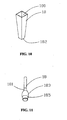
- the sound conducting conduit 18 is a straight circular tube with a tapered structure from the outer opening end 180 to the inner opening end 182, like a trumpet. That is, the inner opening end 182 has a smaller diameter than the outer opening end 180.
- the sound conducting conduit 18 in FIG. 10 is a straight cubic tube with a tapered structure from the outer opening end 180 to the inner opening end 182.
- the sound conducting conduit 18 is substantially a straight tube and includes a drum-shaped portion and a narrow straight tubular portion.
- the narrow opening end has a relatively smaller diameter than the drum-shaped portion, and thus the sound conducting conduit 18 is provided with a large opening end and a narrow opening end opposite to the large opening end.
- the drum-shaped portion is substantially gyrorotor and includes three segments, e.g., an exterior end segment 181 with the large opening end, a drum segment 183 and a transition segment 185 coupling the drum segment 183 to narrow straight tubular portion.
- the sound conducting conduit 18 is seemed to be a conch or functioned as a conch.
- the sound emission means 16 could include any combination of these sound conducting conduits 18 with various shapes above-mentioned.
- the sound conducting conduits 18 are made of many kinds of available materials which aid in conduction and propagation of sound and have no influence on sound quality.
- the available materials could be a material used in typical musical instruments, for example, copper or wood.
- the cross section of the sound conducting conduit 18 could be in a polygon shape, for example, triangle, pentagon or more. It is to be appreciated that various variations about the sound conducting conduit are construed in the scope of the present invention.
- the sound emission device 14 is coupled to the speaker body 12 by means of mechanical engagement, for example, a snapping means, a welding means or a screw means.
- the base 162 of the sound emission means 16 is provided with a fastening member by that the base 162 is attached to the speaker body 12.
- the loudspeaker 164 is coupled to the speaker body 12 or the base 162 by means of mechanical engagement, for example, a snapping means, a welding means or a screw means.
- the sound conducting conduits 18 are coupled to the sphere mask 165 on the loudspeaker 164 by means of mechanical engagement, for example, a snapping means, a welding means or a screw means.
- each parts of the sound emission device 14 can be assembled together with the speaker body 12 by means of mechanical engagement, and thus do not require complex speaker structure and connection means, complicated digital process device and digital process circuit.
- the sound emission system 10 is easy to assemble and occupies small space.
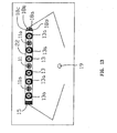
- FIG. 12 illustrates an alternative multi-directional sound emission system 20 having the above multi-directional sound emission means 16.
- the multi-directional sound emission system 20 is substantially similar to the above-described multi-directional sound emission system 10, except that the sound emission system 20 is a five-audio channel sound system.
- the reference numbers used in FIG.12 are substantially similar to those in FIG. 3 and the parts designated by the same reference numbers to FIG. 3 are substantially similar to those parts described above.
- the sound emission system 20 includes a speaker body 22 and the above two sound emission devices 14 coupled to both ends of the speaker body 22.
- the two sound emission devices 14 is respectively serve as a left surround audio channel and a right surround audio channel, as described above.
- the structure of the sound emission devices 14 could be, e.g., shown in FIGS. 3 and 4 .
- the speaker body 22 is provided with three audio channels, e.g., a front left audio channel, a front right audio channel and a center audio channel.
- the center audio channel includes the middle frequency controller 11 and the two speakers 13, similarly to those described above in the first embodiment.
- the front left audio channel and the front right audio channel are coupled to both ends of the center audio channel and have similar construction to the center audio channel.
- the left and right audio channels each include an audio middle frequency controller 11a and two speakers 13a respectively disposed at both ends of the middle frequency controller 11a.
- the middle frequency controller 11a and the two speakers 13a are respectively similar to the middle frequency controller 11 and the two speakers 13.
- the center audio channel, the front left audio channel, the front right audio channel, the left surround audio channel and the right surround audio channel constitute cooperatively constitute a five-audio channel structure of the sound emission system 20.
- the sound emission system 20 is essentially a 5.1ch surround sound system with the five audio channels integrated together with the speaker body 22 as a whole.
- the sound emission system 20 can be positioned adjacent to some music sources or display devices, for example, Television Set, Music Television (MTV), cinema screen to transfer the music or sound to the viewers or listeners by the five audio channels thereof, thereby achieving a 5.1 ch surround effect. That is, in case that the sound emission system 20 is disposed at the front of the listener, the 5.1 ch surround effect is achieved without requiring additional separate speakers. As shown in FIGS.
- part of sound transferred from the sound conducting conduits 18 is reflected towards the listener once by the sidewalls to form an imaginary side sound source, such that the listener (e.g., locating at the listening location 19) feels that this part of sound is emitted from both sides.
- Part of sound transferred from the sound conducting conduits 18 is reflected towards the listener once by the ceiling to form an imaginary top sound source, such that the listener feels that this part of sound is emitted from the ceiling.
- Part of sound transferred from the sound conducting conduits 18 is reflected towards the listener twice by the sidewalls or the ceiling and then by the rear wall to form an imaginary back sound source, such that the listener feels that this part of sound is emitted from back thereof.
- the present sound emission system 20 is devoid of a number of separate speakers surrounding the listening location 19, as required in the traditional sound devices.
- the multi-directional sound emission means 16 essentially use mechanical structure, e.g., the sound conducting elements 18 to achieve sound propagation along various directions, orientations, and angles. It is to be appreciated that some further sound emission means 16 could be arranged at desired portion of the speaker body 12, e.g., top of the speaker body 12 to achieve more than five sound audio channels, for example seven audio channels or more.
- the sound emission means 36 includes an enclosure 362 and a plurality of separators 364.
- the enclosure 362 is functioned as a base like the base 162.
- the enclosure 362 includes a top portion and a bottom portion respectively extending along a top surface and a bottom surface of the speaker body 12 and thus is in a hopper shape.
- the separators 364 are arranged in the enclosure 362 in an array form and are intersecting to each other, e.g., forming a crisscross arrangement.
- the array of separators 364 includes a vertical array of separators 364 and a horizontal array of separators 364.
- the vertical and horizontal arrays of separators 364 cooperatively define the plurality of mechanical sound conducting elements 38 therebetween. Accordingly, the mechanical sound conducting elements 38 are aligned in an array form.
- Each of the sound conducting elements 38 has a through-hole and may be a rectangular tube.
- the separators 364 may be a fan-shaped panel, thereby forming the sound conducting elements 38 with tapered cross-sectional size therebetween.
- the sound conducting elements 38 are substantially similar to the rectangular sound conducting conduits 18 in FIG. 10 .
- the array of sound conducting elements 38 in FIG. 15 could be formed by assembling a number of rectangular sound conducting conduits 18 in FIG. 10 side by side, for example using solder or adhesive.
- a loudspeaker is provided at the bottom (e.g., narrow end) of the enclosure 362 and is in sound communication with the sound source of the speaker body 12.
- the arrangement of the loudspeaker is substantially similar to that of the loudspeaker 164, as shown in FIG. 2 , except that the sound conducting elements 38 are in a rectangular shape.
- Each sound conducting element 18 has an inner opening end and an exterior opening end opposite to the inner opening end. The inner opening end of the sound conducting element 18 is in sound communication with the loudspeaker.
- the plurality of sound conducting elements 38 includes a group of front sound conducting conduits, a group of lateral sound conducting conduits, a group of upper sound conducting conduits, and a group of lower sound conducting conduits.
- Each of the four groups of sound conducting elements includes at least one rectangular sound conducting tube. In this way, the sound conducting elements 38 at both ends of the speaker body 12 form a left surround sound audio channel and a right sound audio channel relative to the listening location 19.
- a multi-directional sound emission system 30 having the sound emission means 36 is shown.
- the multi-directional sound emission system 30 is substantially similar to the above-described multi-directional sound emission system 10, except of the sound emission means 36.
- the reference numbers used in FIG. 16 are substantially similar to those in FIG. 3 and the parts designated by the same reference numbers to FIG. 1 are substantially similar to those parts described above.
- the sound emission means 36 has a plurality of mechanical sound conducting elements 38.
- FIG. 17 another multi-directional sound emission system 40 having the sound emission means 36 is shown.
- the multi-directional sound emission system 40 is substantially similar to the above-described multi-directional sound emission system 30, except that the sound emission system 40 is a five-audio channel sound system.
- the reference numbers used in FIG.17 are substantially similar to those in FIGS. 12 , 15-16 and the parts designated by the same reference numbers to FIGS. 12 , 15-16 are substantially similar to those parts described above.
- the five-audio channel sound system of the sound emission system 40 has the same structure to the five-audio channel sound system of the sound emission system 20.
- the multi-directional sound emission system 40 includes the above speaker body 22 and the above two sound emission devices 14 coupled to both ends of the speaker body 22.
- the speaker body 22 is similar to the speaker body 22 in FIG. 12 , e.g., including three pairs of center loudspeakers 13, 13a.
- the two sound emission devices 14 and the three pairs of center loudspeakers 13, 13a cooperatively constitute the five-audio channel sound system of the sound emission system 40.
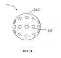
- FIG. 18 illustrates a sound emission means 56 in accordance with a third embodiment of the present invention.
- the sound emission means 56 is in a sphere shape and includes a spherical base 562.
- the base 562 could be in a shape of hemisphere, frustum of sphere, or the likes.
- the base 562 defines a plurality of sound conducting through-holes 58 as mechanical sound conducting elements.
- the plurality of sound conducting through-holes 58 could be defined in part (e.g., half or quarter) of the spherical base 562.
- the sound conducting through-holes 58 usefully extend along radial directions which are converged to a spherical center of the spherical base 562. It is to be understood that the arrangement of the sound conducting through-holes 58 defined in the spherical base 562 could be designed according to actual demands.
- a loudspeaker may be disposed inside the spherical base 562, for example at a center thereof, or be attached the spherical base 562.
- Each sound conducting through-hole 58 is in sound communication with sound exit (e.g., opening 166 of FIG. 1 ) of the loudspeaker.
- each sound conducting through-hole 58 has an exterior opening end and an inner opening end opposite to the exterior opening end. The inner opening end of the sound conducting through-hole 58 is in sound communication with sound exit of the loudspeaker.
- the sound conducting through-holes 58 are beneficially arranged in a uniform interval and have an identical or varying hole size.
- the sound conducting through-holes 58 include a group of front sound conducting through-holes, a group of lateral sound conducting through-holes, a group of upper sound conducting through-holes, and a group of lower sound conducting through-holes, thereby achieving a left surround sound audio channel and a right surround sound audio channel relative to the listening location.
- Each of the four groups of sound conducting through-holes includes at least one circular or rectangular through-hole. Accordingly, the sound conducting through-holes 58 and the three audio channels in the speaker body 52 cooperatively form a 5.1ch surround sound system.
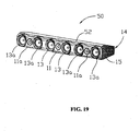
- FIG. 19 illustrates a multi-directional sound emission system 50 having the above sound emission means 56.
- the multi-directional sound emission system 50 is essentially similar to the above-described multi-directional sound emission system 20, except of the sound emission means 56.
- the reference numbers used in FIG.19 are substantially similar to those in FIG. 12 and the parts designated by the same reference numbers to FIG. 12 are substantially similar to those parts described above.
- the multi-directional sound emission system 50 includes a speaker body 52 and the above two sound emission devices 14 coupled to both ends of the speaker body 52.
- the speaker body 52 is similar to the speaker body 22 in FIG. 12 , except that the outline of the speaker body 52 is streamlined. That is, a casing of the speaker body 52 is provided with streamlined edges, but not straight linear edges as illustrated in FIG. 12 .
- the sound conducting conduits 18, the sound conducting conduits 38 and the sound conducting through-holes 58 described above could be replaced with one another but are not limited to be applied the above respective embodiments.
- the sound emission means could be designed to be a desired configuration for actual demands and be not limited to the above-mentioned structure.
- a plurality of hollow mechanical sound conducting elements is provided. Sound from the loudspeaker can be directed the desired multiple directions according to actual demands through the sound conducting elements, accordingly achieving surround sound effect. Thus, the listener situated at any position of a room can receive sound from multiple directions to obtain a stereophonic effect.
- the present multi-directional sound emission system has a combined sound body and sound emission means and thus is free of the multiple separate speakers which are required in traditional sound system.
- the plurality of hollow mechanical sound conducting elements is easy to be integrated with the sound body to achieve a desired multi-audio channel output, without many complex speakers, expensive digital process devices or complicated digital circuit.
- the present multi-directional sound emission means and system both have a compact structure and a reduced cost, and is easy to assemble.
- the plurality of hollow mechanical sound conducting elements use acoustic principle to carry out a directive sound propagation, accordingly, multi-audio channel outputs can synchronously be achieved based on a single front sound body (sound source). Since the present system does not require additional separate speakers around the listener, thus greatly reducing space of the system.
- the multi-directional sound emission means can be readily and easily assembled at both ends (one end in a certain case) of the speaker body of the system, thereby reducing use space for the system and providing convenience for carrying or moving away the system.
Landscapes
- Health & Medical Sciences (AREA)
- Otolaryngology (AREA)
- Physics & Mathematics (AREA)
- Engineering & Computer Science (AREA)
- Acoustics & Sound (AREA)
- Signal Processing (AREA)
- Obtaining Desirable Characteristics In Audible-Bandwidth Transducers (AREA)
- Circuit For Audible Band Transducer (AREA)
Claims (13)
- Multidirektionales Schallemissionsmittel (16), umfassend
eine Basis (162);
einen auf der Basis (162) angeordneten Lautsprecher (164), wobei der Lautsprecher (164) eine Öffnung aufweist, aus der der Schall ausgesendet wird; und
drei oder mehr hohle mechanische schallleitende Elemente (18), wobei jedes hohle mechanische schallleitende Element (18) ein inneres Öffnungsende (182) und ein äußeres Öffnungsende (180) gegenüber dem inneren Öffnungsende (182) aufweist, wobei die äußeren Öffnungsenden (180) der schallleitenden Elemente (18) jeweils in gewünschte mehrere Richtungen gerichtet sind, wobei die inneren Öffnungsenden (182) der mechanischen schallleitenden Elemente (18) in akustischer Verbindung mit der Öffnung des Lautsprechers (164) stehen, sodass durch die schallleitenden Elemente (18) Schall vom Lautsprecher (164) in die gewünschten mehreren Richtungen ausgesendet wird,
dadurch gekennzeichnet, dass:die drei oder mehr mechanischen schallleitenden Elemente (18) in einer dreidimensionalen Richtung radial verteilt sind, um Schall in drei oder mehr Richtungen dreidimensional auszusenden und die mechanischen schallleitenden Elemente (18) sich radial aus der Basis (162) heraus erstreckende schallleitende Kanäle sind. - Multidirektionales Schallemissionsmittel (16) nach Anspruch 1, wobei die schallleitenden Kanäle (18) ausgewählt sind aus der Gruppe bestehend aus: einem geraden Rohr, einem gekrümmten Rohr, einem konisch zulaufenden Rohr und einem Rohr mit einer rechteckigen Öffnung.
- Multidirektionales Schallemissionsmittel nach Anspruch einem der Ansprüche 1 bis 2, wobei die Basis (562) eine Form aufweist, die ausgewählt ist aus der Gruppe bestehend aus: Kugel, Halbkugel, Kugelstumpf und Gehäuse.
- Multidirektionales Schallemissionsmittel nach einem der Ansprüche 1 bis 3, wobei die Basis ein Gehäuse (362) ist, wobei drei oder mehr Separatoren (364) in dem Gehäuse (362) in einer Arrayform angeordnet sind und einander so schneiden, dass dazwischen die schallleitenden Elemente (38) definiert sind.
- Multidirektionales Schallemissionsmittel nach einem der Ansprüche 1 bis 4, wobei die Separatoren (364) fächerförmige Platten sind und in Zusammenwirkung die schallleitenden Elemente (18) mit sich verjüngender Querschnittsgröße bilden.
- Multidirektionales Schallemissionsmittel nach einem der Ansprüche 1 bis 5, wobei die Basis (562) eine Form aufweist, die ausgewählt ist aus der Gruppe bestehend aus: Kugel, Halbkugel und Kugelstumpf, wobei die Basis drei oder mehr schallleitende Durchgangslöcher (58) definiert, die sich als die mechanischen schallleitenden Elemente radial nach außen erstrecken.
- Multidirektionales Schallemissionsmittel nach einem der Ansprüche 1 bis 6, wobei die drei oder mehr mechanischen schallleitenden Elemente (18) eine Gruppe vorderer schallleitender Elemente (18a), eine Gruppe seitlicher schallleitender Elemente (18b), eine Gruppe oberer schallleitender Elemente (18c) und eine Gruppe unterer schallleitender Elemente (18d) umfassen, wobei die vorderen schallleitenden Elemente (18a) zur Schallausbreitung in einer Vorwärtsrichtung direkt oder schräg zur Vorderseite des Lautsprecherkörpers (12) gerichtet sind, die seitlichen schallleitenden Elemente (18b) zur Schallausbreitung in einer seitlichen Richtung direkt oder schräg zur Seite des Lautsprecherkörpers (12) gerichtet sind, die oberen schallleitenden Elemente (18c) zur Schallausbreitung in einer Aufwärtsrichtung direkt oder schräg zur Oberseite des Lautsprecherkörpers (12) gerichtet sind, die unteren schallleitenden Elemente (18d) zur Schallausbreitung in einer Abwärtsrichtung direkt oder schräg zur Unterseite des Lautsprecherkörpers (12) gerichtet sind.
- Multidirektionales Schallemissionsmittel nach einem der Ansprüche 1 bis 7, wobei die äußeren Öffnungsenden (180) der schallleitenden Elemente (18) als ein kugelförmiges Profil oder ein gekrümmtes Profil erscheinen.
- Multidirektionales Schallemissionsmittel nach einem der Ansprüche 1 bis 8, wobei eine Maske (165) über die Öffnung (166) des Lautsprechers (164) gelegt ist, wobei das innere Öffnungsende (182) jedes schallleitenden Kanals (18) durch die Kugelmaske (165) dringt, um in akustischer Verbindung mit dem Lautsprecher (164) zu stehen.
- Multidirektionales Schallemissionssystem, umfassend
einen Lautsprecherkörper (12); und
an beide gegenüberliegenden Enden des Lautsprecherkörpers (12) gekoppelte Schallemissionsvorrichtungen (14), wobei jede Schallemissionsvorrichtung (14) ein multidirektionales Schallemissionsmittel (16) nach einem der Ansprüche 1 bis 9 umfasst, das ausgelegt ist zum gerichteten Aussenden von Schall in mehrere Richtungen. - Multidirektionales Schallemissionssystem nach Anspruch 10, wobei der Lautsprecherkörper (12) und die an beide Enden desselben gekoppelten Schallemissionsvorrichtungen (14) als Ganzes integriert sind.
- Multidirektionales Schallemissionssystem nach Anspruch 10 oder 11, wobei der Lautsprecherkörper (12) zumindest einen Mittenfrequenzregler (11) und zwei an beide Enden des Mittenfrequenzreglers (11) gekoppelte Lautsprecher (13) zur Ausbildung eines mittleren Audiokanals umfasst.
- Mehrdirektionales Schallemissionssystem nach einem der Ansprüche 10 bis 12, wobei der Lautsprecherkörper (12) drei Audiokanäle umfasst, wobei jeder Audiokanal einen Mittenfrequenzregler (11) und zwei an beide Enden des Mittenfrequenzreglers (11) gekoppelte Lautsprecher (13) umfasst.
Applications Claiming Priority (1)
| Application Number | Priority Date | Filing Date | Title |
|---|---|---|---|
| CN2009101090428A CN101964933A (zh) | 2009-07-23 | 2009-07-23 | 多方向发声结构和多方向发声系统 |
Publications (3)
| Publication Number | Publication Date |
|---|---|
| EP2293597A2 EP2293597A2 (de) | 2011-03-09 |
| EP2293597A3 EP2293597A3 (de) | 2012-08-29 |
| EP2293597B1 true EP2293597B1 (de) | 2014-08-27 |
Family
ID=42830389
Family Applications (1)
| Application Number | Title | Priority Date | Filing Date |
|---|---|---|---|
| EP10158882.0A Not-in-force EP2293597B1 (de) | 2009-07-23 | 2010-03-31 | Multidirektionale Schallemissionsmittel und multidirektionales Schallemissionssystem |
Country Status (4)
| Country | Link |
|---|---|
| US (1) | US8351640B2 (de) |
| EP (1) | EP2293597B1 (de) |
| CN (1) | CN101964933A (de) |
| WO (1) | WO2011009310A1 (de) |
Families Citing this family (11)
| Publication number | Priority date | Publication date | Assignee | Title |
|---|---|---|---|---|
| JP5626461B2 (ja) * | 2011-05-11 | 2014-11-19 | パナソニック株式会社 | 映像表示装置 |
| US9485556B1 (en) * | 2012-06-27 | 2016-11-01 | Amazon Technologies, Inc. | Speaker array for sound imaging |
| CN104183219B (zh) | 2013-12-30 | 2017-02-15 | 昆山工研院新型平板显示技术中心有限公司 | 扫描驱动电路和有机发光显示器 |
| US9859510B2 (en) | 2015-05-15 | 2018-01-02 | Universal Display Corporation | Organic electroluminescent materials and devices |
| EP3429224A1 (de) | 2017-07-14 | 2019-01-16 | Fraunhofer-Gesellschaft zur Förderung der angewandten Forschung e.V. | Lautsprecher |
| US10544933B2 (en) | 2018-04-04 | 2020-01-28 | Abl Ip Holding Llc | Light fixture with rotatable speakers |
| USD883548S1 (en) | 2018-04-27 | 2020-05-05 | Abl Ip Holding Llc | Light fixture with rotatable end |
| US10205749B1 (en) | 2018-08-17 | 2019-02-12 | Five Media Marketing Limited | Detection and prevention of automatic redirects of main html document from within nested sub-document |
| US11128644B2 (en) | 2019-03-19 | 2021-09-21 | Five Media Marketing Limited | Automatic security scanning of advertisements during runtime of software applications |
| WO2021205591A1 (ja) * | 2020-04-09 | 2021-10-14 | 日本電信電話株式会社 | スピーカアレイ |
| EP4424028A1 (de) * | 2021-10-27 | 2024-09-04 | Magic Leap, Inc. | Akustischer wiedergabewellenleiter für tragbare xr-brille |
Family Cites Families (9)
| Publication number | Priority date | Publication date | Assignee | Title |
|---|---|---|---|---|
| US526046A (en) * | 1894-09-18 | mckelvey | ||
| US2096192A (en) * | 1937-07-01 | 1937-10-19 | Aston L Moore | Loudspeaker unit |
| JPH07177443A (ja) * | 1993-12-16 | 1995-07-14 | Toshiba Corp | テレビジョンセットのスピーカシステム |
| US7010138B1 (en) * | 1996-09-03 | 2006-03-07 | New Transducers Limited | Loudspeakers |
| CN2489531Y (zh) * | 2001-04-30 | 2002-05-01 | 梁垣明 | 一种多方位仿岩石音箱 |
| FI116506B (fi) * | 2003-07-08 | 2005-11-30 | Harri Hietala | Ympärisäteilevä stereokaiutin |
| US7356155B2 (en) * | 2003-07-18 | 2008-04-08 | Lazarus Technologies, Inc. | Device and method for assisting vocalists in hearing their vocal sounds |
| CN2792070Y (zh) * | 2005-05-14 | 2006-06-28 | 深圳东原电子有限公司 | 具有多向扩散功能的高音扬声器 |
| GB2437125B (en) * | 2006-04-13 | 2011-02-09 | Gp Acoustics | Phase plug for compression driver |
-
2009
- 2009-07-23 CN CN2009101090428A patent/CN101964933A/zh active Pending
-
2010
- 2010-02-26 US US12/713,987 patent/US8351640B2/en not_active Expired - Fee Related
- 2010-03-31 WO PCT/CN2010/071469 patent/WO2011009310A1/zh active Application Filing
- 2010-03-31 EP EP10158882.0A patent/EP2293597B1/de not_active Not-in-force
Also Published As
| Publication number | Publication date |
|---|---|
| EP2293597A2 (de) | 2011-03-09 |
| EP2293597A3 (de) | 2012-08-29 |
| US20110019853A1 (en) | 2011-01-27 |
| US8351640B2 (en) | 2013-01-08 |
| WO2011009310A1 (zh) | 2011-01-27 |
| CN101964933A (zh) | 2011-02-02 |
Similar Documents
| Publication | Publication Date | Title |
|---|---|---|
| EP2293596B1 (de) | Multidirektionales Tonausgabesystem | |
| EP2293597B1 (de) | Multidirektionale Schallemissionsmittel und multidirektionales Schallemissionssystem | |
| JP4127156B2 (ja) | オーディオ再生装置、ラインアレイスピーカユニットおよびオーディオ再生方法 | |
| RU2573037C2 (ru) | Громкоговорящее устройство с круговым воронкообразным звуковым выходным отверстием | |
| US6996243B2 (en) | Loudspeaker with shaped sound field | |
| US8081775B2 (en) | Loudspeaker apparatus for radiating acoustic waves in a hemisphere around the centre axis | |
| US6016353A (en) | Large scale sound reproduction system having cross-cabinet horizontal array of horn elements | |
| KR20050101571A (ko) | 사운드 빔 스피커 장치 | |
| JP2018527808A (ja) | サウンドバー | |
| JPH06197293A (ja) | テレビジョンセットのスピーカシステム | |
| EP0872154A1 (de) | Akustisches tonsystem zur erzeugung eines dreidimensionalen klangbildes | |
| GB2535844A (en) | Speaker unit | |
| WO2018231269A1 (en) | Speaker system for high fidelity reproduction of audio signals | |
| JP2013513266A (ja) | フラットスピーカ | |
| US20060251271A1 (en) | Ceiling Mounted Loudspeaker System | |
| JP2007506323A (ja) | ディジタルスピーカ | |
| US10341761B2 (en) | Acoustic waveguide for audio speaker | |
| JPH06284488A (ja) | テレビジョンセットのスピーカシステム | |
| US5949893A (en) | Loudspeaker box | |
| JP2002291086A (ja) | スピーカー装置 | |
| EP3420738B1 (de) | Planarlautsprecherverteiler für verbesserte schalldispersion | |
| KR100260419B1 (ko) | 무지향스피커시스템을위한음향반사판장치 | |
| US20240314494A1 (en) | Narrow aperture waveguide loudspeaker for use with flat panel display devices | |
| KR19990004458A (ko) | 라우드 스피커 시스템 |
Legal Events
| Date | Code | Title | Description |
|---|---|---|---|
| PUAI | Public reference made under article 153(3) epc to a published international application that has entered the european phase |
Free format text: ORIGINAL CODE: 0009012 |
|
| AK | Designated contracting states |
Kind code of ref document: A2 Designated state(s): AT BE BG CH CY CZ DE DK EE ES FI FR GB GR HR HU IE IS IT LI LT LU LV MC MK MT NL NO PL PT RO SE SI SK SM TR |
|
| AX | Request for extension of the european patent |
Extension state: AL BA ME RS |
|
| 17P | Request for examination filed |
Effective date: 20120322 |
|
| PUAL | Search report despatched |
Free format text: ORIGINAL CODE: 0009013 |
|
| AK | Designated contracting states |
Kind code of ref document: A3 Designated state(s): AT BE BG CH CY CZ DE DK EE ES FI FR GB GR HR HU IE IS IT LI LT LU LV MC MK MT NL NO PL PT RO SE SI SK SM TR |
|
| AX | Request for extension of the european patent |
Extension state: AL BA ME RS |
|
| RIC1 | Information provided on ipc code assigned before grant |
Ipc: H04R 1/34 20060101ALI20120724BHEP Ipc: H04R 5/02 20060101AFI20120724BHEP |
|
| 17Q | First examination report despatched |
Effective date: 20130806 |
|
| GRAP | Despatch of communication of intention to grant a patent |
Free format text: ORIGINAL CODE: EPIDOSNIGR1 |
|
| INTG | Intention to grant announced |
Effective date: 20140319 |
|
| GRAS | Grant fee paid |
Free format text: ORIGINAL CODE: EPIDOSNIGR3 |
|
| GRAA | (expected) grant |
Free format text: ORIGINAL CODE: 0009210 |
|
| AK | Designated contracting states |
Kind code of ref document: B1 Designated state(s): AT BE BG CH CY CZ DE DK EE ES FI FR GB GR HR HU IE IS IT LI LT LU LV MC MK MT NL NO PL PT RO SE SI SK SM TR |
|
| REG | Reference to a national code |
Ref country code: GB Ref legal event code: FG4D |
|
| REG | Reference to a national code |
Ref country code: CH Ref legal event code: EP |
|
| REG | Reference to a national code |
Ref country code: AT Ref legal event code: REF Ref document number: 685016 Country of ref document: AT Kind code of ref document: T Effective date: 20140915 |
|
| REG | Reference to a national code |
Ref country code: IE Ref legal event code: FG4D |
|
| REG | Reference to a national code |
Ref country code: DE Ref legal event code: R096 Ref document number: 602010018505 Country of ref document: DE Effective date: 20141009 |
|
| REG | Reference to a national code |
Ref country code: AT Ref legal event code: MK05 Ref document number: 685016 Country of ref document: AT Kind code of ref document: T Effective date: 20140827 |
|
| REG | Reference to a national code |
Ref country code: LT Ref legal event code: MG4D |
|
| REG | Reference to a national code |
Ref country code: NL Ref legal event code: VDEP Effective date: 20140827 |
|
| PG25 | Lapsed in a contracting state [announced via postgrant information from national office to epo] |
Ref country code: GR Free format text: LAPSE BECAUSE OF FAILURE TO SUBMIT A TRANSLATION OF THE DESCRIPTION OR TO PAY THE FEE WITHIN THE PRESCRIBED TIME-LIMIT Effective date: 20141128 Ref country code: LT Free format text: LAPSE BECAUSE OF FAILURE TO SUBMIT A TRANSLATION OF THE DESCRIPTION OR TO PAY THE FEE WITHIN THE PRESCRIBED TIME-LIMIT Effective date: 20140827 Ref country code: FI Free format text: LAPSE BECAUSE OF FAILURE TO SUBMIT A TRANSLATION OF THE DESCRIPTION OR TO PAY THE FEE WITHIN THE PRESCRIBED TIME-LIMIT Effective date: 20140827 Ref country code: ES Free format text: LAPSE BECAUSE OF FAILURE TO SUBMIT A TRANSLATION OF THE DESCRIPTION OR TO PAY THE FEE WITHIN THE PRESCRIBED TIME-LIMIT Effective date: 20140827 Ref country code: SE Free format text: LAPSE BECAUSE OF FAILURE TO SUBMIT A TRANSLATION OF THE DESCRIPTION OR TO PAY THE FEE WITHIN THE PRESCRIBED TIME-LIMIT Effective date: 20140827 Ref country code: NO Free format text: LAPSE BECAUSE OF FAILURE TO SUBMIT A TRANSLATION OF THE DESCRIPTION OR TO PAY THE FEE WITHIN THE PRESCRIBED TIME-LIMIT Effective date: 20141127 Ref country code: BG Free format text: LAPSE BECAUSE OF FAILURE TO SUBMIT A TRANSLATION OF THE DESCRIPTION OR TO PAY THE FEE WITHIN THE PRESCRIBED TIME-LIMIT Effective date: 20141127 Ref country code: PT Free format text: LAPSE BECAUSE OF FAILURE TO SUBMIT A TRANSLATION OF THE DESCRIPTION OR TO PAY THE FEE WITHIN THE PRESCRIBED TIME-LIMIT Effective date: 20141229 |
|
| PG25 | Lapsed in a contracting state [announced via postgrant information from national office to epo] |
Ref country code: IS Free format text: LAPSE BECAUSE OF FAILURE TO SUBMIT A TRANSLATION OF THE DESCRIPTION OR TO PAY THE FEE WITHIN THE PRESCRIBED TIME-LIMIT Effective date: 20141227 Ref country code: CY Free format text: LAPSE BECAUSE OF FAILURE TO SUBMIT A TRANSLATION OF THE DESCRIPTION OR TO PAY THE FEE WITHIN THE PRESCRIBED TIME-LIMIT Effective date: 20140827 Ref country code: LV Free format text: LAPSE BECAUSE OF FAILURE TO SUBMIT A TRANSLATION OF THE DESCRIPTION OR TO PAY THE FEE WITHIN THE PRESCRIBED TIME-LIMIT Effective date: 20140827 Ref country code: HR Free format text: LAPSE BECAUSE OF FAILURE TO SUBMIT A TRANSLATION OF THE DESCRIPTION OR TO PAY THE FEE WITHIN THE PRESCRIBED TIME-LIMIT Effective date: 20140827 Ref country code: AT Free format text: LAPSE BECAUSE OF FAILURE TO SUBMIT A TRANSLATION OF THE DESCRIPTION OR TO PAY THE FEE WITHIN THE PRESCRIBED TIME-LIMIT Effective date: 20140827 |
|
| REG | Reference to a national code |
Ref country code: FR Ref legal event code: PLFP Year of fee payment: 6 |
|
| PG25 | Lapsed in a contracting state [announced via postgrant information from national office to epo] |
Ref country code: NL Free format text: LAPSE BECAUSE OF FAILURE TO SUBMIT A TRANSLATION OF THE DESCRIPTION OR TO PAY THE FEE WITHIN THE PRESCRIBED TIME-LIMIT Effective date: 20140827 |
|
| PG25 | Lapsed in a contracting state [announced via postgrant information from national office to epo] |
Ref country code: CZ Free format text: LAPSE BECAUSE OF FAILURE TO SUBMIT A TRANSLATION OF THE DESCRIPTION OR TO PAY THE FEE WITHIN THE PRESCRIBED TIME-LIMIT Effective date: 20140827 Ref country code: DK Free format text: LAPSE BECAUSE OF FAILURE TO SUBMIT A TRANSLATION OF THE DESCRIPTION OR TO PAY THE FEE WITHIN THE PRESCRIBED TIME-LIMIT Effective date: 20140827 Ref country code: RO Free format text: LAPSE BECAUSE OF FAILURE TO SUBMIT A TRANSLATION OF THE DESCRIPTION OR TO PAY THE FEE WITHIN THE PRESCRIBED TIME-LIMIT Effective date: 20140827 Ref country code: SK Free format text: LAPSE BECAUSE OF FAILURE TO SUBMIT A TRANSLATION OF THE DESCRIPTION OR TO PAY THE FEE WITHIN THE PRESCRIBED TIME-LIMIT Effective date: 20140827 Ref country code: EE Free format text: LAPSE BECAUSE OF FAILURE TO SUBMIT A TRANSLATION OF THE DESCRIPTION OR TO PAY THE FEE WITHIN THE PRESCRIBED TIME-LIMIT Effective date: 20140827 |
|
| REG | Reference to a national code |
Ref country code: DE Ref legal event code: R097 Ref document number: 602010018505 Country of ref document: DE |
|
| PG25 | Lapsed in a contracting state [announced via postgrant information from national office to epo] |
Ref country code: PL Free format text: LAPSE BECAUSE OF FAILURE TO SUBMIT A TRANSLATION OF THE DESCRIPTION OR TO PAY THE FEE WITHIN THE PRESCRIBED TIME-LIMIT Effective date: 20140827 |
|
| PLBE | No opposition filed within time limit |
Free format text: ORIGINAL CODE: 0009261 |
|
| STAA | Information on the status of an ep patent application or granted ep patent |
Free format text: STATUS: NO OPPOSITION FILED WITHIN TIME LIMIT |
|
| 26N | No opposition filed |
Effective date: 20150528 |
|
| PG25 | Lapsed in a contracting state [announced via postgrant information from national office to epo] |
Ref country code: MC Free format text: LAPSE BECAUSE OF FAILURE TO SUBMIT A TRANSLATION OF THE DESCRIPTION OR TO PAY THE FEE WITHIN THE PRESCRIBED TIME-LIMIT Effective date: 20140827 Ref country code: LU Free format text: LAPSE BECAUSE OF FAILURE TO SUBMIT A TRANSLATION OF THE DESCRIPTION OR TO PAY THE FEE WITHIN THE PRESCRIBED TIME-LIMIT Effective date: 20150331 |
|
| REG | Reference to a national code |
Ref country code: CH Ref legal event code: PL |
|
| GBPC | Gb: european patent ceased through non-payment of renewal fee |
Effective date: 20150331 |
|
| PG25 | Lapsed in a contracting state [announced via postgrant information from national office to epo] |
Ref country code: SI Free format text: LAPSE BECAUSE OF FAILURE TO SUBMIT A TRANSLATION OF THE DESCRIPTION OR TO PAY THE FEE WITHIN THE PRESCRIBED TIME-LIMIT Effective date: 20140827 |
|
| REG | Reference to a national code |
Ref country code: IE Ref legal event code: MM4A |
|
| PG25 | Lapsed in a contracting state [announced via postgrant information from national office to epo] |
Ref country code: GB Free format text: LAPSE BECAUSE OF NON-PAYMENT OF DUE FEES Effective date: 20150331 Ref country code: LI Free format text: LAPSE BECAUSE OF NON-PAYMENT OF DUE FEES Effective date: 20150331 Ref country code: IE Free format text: LAPSE BECAUSE OF NON-PAYMENT OF DUE FEES Effective date: 20150331 Ref country code: CH Free format text: LAPSE BECAUSE OF NON-PAYMENT OF DUE FEES Effective date: 20150331 |
|
| REG | Reference to a national code |
Ref country code: FR Ref legal event code: PLFP Year of fee payment: 7 |
|
| PG25 | Lapsed in a contracting state [announced via postgrant information from national office to epo] |
Ref country code: BE Free format text: LAPSE BECAUSE OF FAILURE TO SUBMIT A TRANSLATION OF THE DESCRIPTION OR TO PAY THE FEE WITHIN THE PRESCRIBED TIME-LIMIT Effective date: 20140827 |
|
| PG25 | Lapsed in a contracting state [announced via postgrant information from national office to epo] |
Ref country code: MT Free format text: LAPSE BECAUSE OF FAILURE TO SUBMIT A TRANSLATION OF THE DESCRIPTION OR TO PAY THE FEE WITHIN THE PRESCRIBED TIME-LIMIT Effective date: 20140827 |
|
| REG | Reference to a national code |
Ref country code: FR Ref legal event code: PLFP Year of fee payment: 8 |
|
| PG25 | Lapsed in a contracting state [announced via postgrant information from national office to epo] |
Ref country code: HU Free format text: LAPSE BECAUSE OF FAILURE TO SUBMIT A TRANSLATION OF THE DESCRIPTION OR TO PAY THE FEE WITHIN THE PRESCRIBED TIME-LIMIT; INVALID AB INITIO Effective date: 20100331 Ref country code: SM Free format text: LAPSE BECAUSE OF FAILURE TO SUBMIT A TRANSLATION OF THE DESCRIPTION OR TO PAY THE FEE WITHIN THE PRESCRIBED TIME-LIMIT Effective date: 20140827 |
|
| PG25 | Lapsed in a contracting state [announced via postgrant information from national office to epo] |
Ref country code: TR Free format text: LAPSE BECAUSE OF FAILURE TO SUBMIT A TRANSLATION OF THE DESCRIPTION OR TO PAY THE FEE WITHIN THE PRESCRIBED TIME-LIMIT Effective date: 20140827 |
|
| REG | Reference to a national code |
Ref country code: FR Ref legal event code: PLFP Year of fee payment: 9 |
|
| PGFP | Annual fee paid to national office [announced via postgrant information from national office to epo] |
Ref country code: DE Payment date: 20180322 Year of fee payment: 9 |
|
| PGFP | Annual fee paid to national office [announced via postgrant information from national office to epo] |
Ref country code: FR Payment date: 20180328 Year of fee payment: 9 |
|
| PG25 | Lapsed in a contracting state [announced via postgrant information from national office to epo] |
Ref country code: MK Free format text: LAPSE BECAUSE OF FAILURE TO SUBMIT A TRANSLATION OF THE DESCRIPTION OR TO PAY THE FEE WITHIN THE PRESCRIBED TIME-LIMIT Effective date: 20140827 |
|
| PGFP | Annual fee paid to national office [announced via postgrant information from national office to epo] |
Ref country code: IT Payment date: 20180327 Year of fee payment: 9 |
|
| REG | Reference to a national code |
Ref country code: DE Ref legal event code: R119 Ref document number: 602010018505 Country of ref document: DE |
|
| PG25 | Lapsed in a contracting state [announced via postgrant information from national office to epo] |
Ref country code: DE Free format text: LAPSE BECAUSE OF NON-PAYMENT OF DUE FEES Effective date: 20191001 |
|
| PG25 | Lapsed in a contracting state [announced via postgrant information from national office to epo] |
Ref country code: FR Free format text: LAPSE BECAUSE OF NON-PAYMENT OF DUE FEES Effective date: 20190331 Ref country code: IT Free format text: LAPSE BECAUSE OF NON-PAYMENT OF DUE FEES Effective date: 20190331 |