EP2293221B1 - Apparatus, method, and program for processing image - Google Patents
Apparatus, method, and program for processing image Download PDFInfo
- Publication number
- EP2293221B1 EP2293221B1 EP10173731.0A EP10173731A EP2293221B1 EP 2293221 B1 EP2293221 B1 EP 2293221B1 EP 10173731 A EP10173731 A EP 10173731A EP 2293221 B1 EP2293221 B1 EP 2293221B1
- Authority
- EP
- European Patent Office
- Prior art keywords
- face
- parameter
- image
- avatar
- user
- Prior art date
- Legal status (The legal status is an assumption and is not a legal conclusion. Google has not performed a legal analysis and makes no representation as to the accuracy of the status listed.)
- Not-in-force
Links
Images


Classifications
-
- G—PHYSICS
- G06—COMPUTING OR CALCULATING; COUNTING
- G06T—IMAGE DATA PROCESSING OR GENERATION, IN GENERAL
- G06T11/00—2D [Two Dimensional] image generation
-
- G—PHYSICS
- G06—COMPUTING OR CALCULATING; COUNTING
- G06V—IMAGE OR VIDEO RECOGNITION OR UNDERSTANDING
- G06V40/00—Recognition of biometric, human-related or animal-related patterns in image or video data
- G06V40/10—Human or animal bodies, e.g. vehicle occupants or pedestrians; Body parts, e.g. hands
- G06V40/16—Human faces, e.g. facial parts, sketches or expressions
- G06V40/168—Feature extraction; Face representation
-
- G—PHYSICS
- G06—COMPUTING OR CALCULATING; COUNTING
- G06T—IMAGE DATA PROCESSING OR GENERATION, IN GENERAL
- G06T11/00—2D [Two Dimensional] image generation
- G06T11/60—Editing figures and text; Combining figures or text
-
- G—PHYSICS
- G06—COMPUTING OR CALCULATING; COUNTING
- G06V—IMAGE OR VIDEO RECOGNITION OR UNDERSTANDING
- G06V40/00—Recognition of biometric, human-related or animal-related patterns in image or video data
- G06V40/10—Human or animal bodies, e.g. vehicle occupants or pedestrians; Body parts, e.g. hands
- G06V40/16—Human faces, e.g. facial parts, sketches or expressions
- G06V40/174—Facial expression recognition
- G06V40/175—Static expression
Definitions
- the present invention relates to an image processing apparatus, an image processing method and an image processing program and, in particular, an image processing apparatus, an image processing method and an image processing program for presenting an image to which a user is more amenable to.
- a typical one of the related-art image processing apparatuses detects a face of a user in an image on a real-time basis, and replaces partly or entirely the image of the face with another image in synchronization with the detected face of the user.
- Japanese Unexamined Patent Application Publication No. 2005-157679 discloses a technique of detecting a face image of any size at a high discrimination performance.
- Japanese Unexamined Patent Application Publication No. 2005-284348 discloses a technique of detecting fast a face image.
- Japanese Unexamined Patent Application Publication No. 2002-232783 discloses a technique of gluing images of a face of a user pre-captured in a plurality of directions in accordance with an orientation of a face image detected from an image.
- a face image pre-captured in this way and a face image detected from an image may be replaced with an avatar produced through computer graphics.
- the expression of the replacing avatar may be synchronized with the change in the facial expression of the user.
- the openness of the eyes of the avatar or the openness of the mouth of the avatar may be varied in accordance with the facial expression of the user.
- the smiling degree of the avatar may be varied in accordance with the smiling degree of the user.
- Japanese Unexamined Patent Application Publication No. 2007-156650 discloses a technique of generating a natural expression of a face.
- Japanese Unexamined Patent Application Publication No. 7-44727 discloses a technique of varying a mouth shape in synchronization with a voice.
- a further example of a prior art avatar generation method is given in the Patent Application Publication US2007/080967 A1 .
- the user may be amenable to an image (such as in a game or a virtual space) by replacing a face of a user in an image with an avatar.
- the user desirably empathizes with the image.
- FIG. 1 is a block diagram of an image processing apparatus of one embodiment of the present invention.
- an image processing apparatus 11 connects to a camera 12 and a display 13.
- the camera 12 includes an imaging device such as a charge coupled device (CCD) or a complentary metal oxide semiconductor (CMOS) sensor, and an imaging optical system including a plurality of lenses.
- the camera 12 supplies an image captured by the imaging device to the image processing apparatus 11 via the imaging optical system.
- CCD charge coupled device
- CMOS complentary metal oxide semiconductor
- the display 13 includes a display device such as a cathode ray tube (CRT), a liquid-crystal display (LCD), a plasma display panel (PDP), or an organic electroluminescence (EL) panel.
- the display 13 is supplied with an image processed by the image processing apparatus 11, and then displays the image.
- the image processing apparatus 11 performs an image processing process to synthesize the face of an avatar, generated through computer graphics, in a region where the face of a user is displayed in an image captured by the camera 12.
- the avatar refers to a character displayed as a picture representing a person in a virtual space for game playing and chatting.
- the face of a character generated through computer graphics and displayed in place of the face of a user is hereinafter referred to as an avatar.
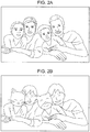
- FIG. 2A illustrates an image captured by the camera 12 and then input to the image processing apparatus 11.
- FIG. 2B illustrates an image processed by the image processing apparatus 11 and then displayed on the display 13.
- the image processing apparatus 11 detects the face of the user presented in the input image, and determines based on an attribute (feature) extracted from the face image whether the face is of an adult, or a child, and a male, or a female.
- the image processing apparatus 11 generates an avatar based on determination results, and generates an output image by synthesizing the avatar with the input image such that the avatar is overlaid at the position of the face of the user.
- An output image having an avatar corresponding to a male adult replacing the face of the male adult presented in the input image is thus displayed.
- An output image having an avatar corresponding to a female adult replacing the face of the female adult presented in the input image is thus displayed.
- FIG. 2B the faces of children presented in the input image are replaced with animal characters as avatars corresponding to the children.
- the image processing apparatus 11 performs, on a real-time basis, an image processing process on a moving image captured by the camera 12. If the expression changes on the user's face, the expression of the avatar can also be changed in synchronization.
- the image processing apparatus 11 includes a camera input unit 14, a face recognizer 15, a model selector 16, a parameter generator 17, and an image generator 18.
- the camera input unit 14 includes a camera controller 21 and a decoder 22.
- the camera controller 21 adjusts exposure and white balance to the camera 12 in response to the image from the camera 12.
- An image input to the camera input unit 14 from the camera 12 is raw data (not image processed data when output from the imaging device).
- the decoder 22 converts the image of the raw data into an image of RGB+Y data (data representing an image of the three primary colors of red, green, and blue, and a luminance signal Y), and then supplies the image to the face recognizer 15.
- the face recognizer 15 includes a face recognition controller 31, a face detection processor 32, a part detector 33, an attribute determiner 34, and a part detail detector 35.
- the face recognizer 15 performs a face recognition process on an image supplied from the decoder 22 in the camera input unit 14.
- the face recognition controller 31 performs a control process on each element in the face recognizer 15. For example, the face recognition controller 31 performs the control process to cause the output of the attribute determiner 34 to be supplied to the model selector 16 throughout a predetermined number of frames (15 frames, for example) starting with a frame from which a new face is detected, and then to be supplied to the parameter generator 17 after the predetermined number of frames.
- a predetermined number of frames 15 frames, for example
- the face detection processor 32 receives an image output from the camera input unit 14 and performs a face detection process to detect from the image a region including the face of the user (hereinafter referred to as a face region). For example, the face detection processor 32 performs the face detection process in two phases of a general search and a local search. In the general search, the face detection processor 32 handles the entire image, thereby searching for a face region of each face presented in the image. In the local search, the face detection processor 32 performs a local search operation, focusing on a face region previously detected in the general search. The face detection processor 32 detects faces (targets) of a plurality of users in the general search while tracking in the local search each face detected in the general search.
- the face detection processor 32 If the face of the user is presented in the image from the camera input unit 14, the face detection processor 32 outputs face detection result information identifying the face region of the face. If a new face, not presented previously in the image, is detected in the general search, the face detection processor 32 starts outputting the face detection result information of the new face. While the face is continuously presented in the image, the face detection processor 32 tracks the face in the local search, and continuously outputs the face detection result information of the face.
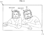
- the face detection result information includes a reference point, a horizontal width, a vertical length, and a rotation angle (faceX, faceY, faceW, faceH, faceRoll, and faceYaw) of the face region.
- the reference point (faceX, faceY) of the face region is normalized with (0, 0) as the top left corner of the entire image and (1, 1) as the bottom right corner of the entire image, and then represented in XY coordinates of the top left corner of the face region.
- the horizontal width and the vertical length (faceW, faceH) of the face region are represented by values that are normalized with a side of the face region, in parallel with a line connecting the two eyes, serving as a horizontal line and a side of the face region, in perpendicular to the horizontal line, serving as a vertical line.
- the rotation angles of the face region (faceRoll, faceYaw) are represented in the right-hand coordinate system to be discussed later in FIG. 6 .
- the part detector 33 detects as parts of the face of the user the right eye, the left eye, the nose, and the mouth of the face in the face region detected by the face detection processor 32, and outputs part information as information indicating coordinates of the center point of each part.
- part information coordinates representing the center point of each of the right eye, the left eye, the nose, and the mouth are normalized with (0,0) representing the reference point (faceX, faceY) as the top left corner of the face region and (1,1) representing the bottom right corner of the face region.
- the part detector 33 determines a position and a posture of the face based on a geometry relationship of the detected parts, and outputs face position information indicating the position and the posture of the face.
- the face position information includes coordinates of the four corners of the face region, and the posture of the face (regionX[0]-[3], regionY[0]-[3], PoseRoll, PosePitch, PoseYaw).
- the face position information is described below with reference to FIG. 4 .
- the coordinates of the four corners of the face region are represented by the values that are normalized with (0,0) representing the top left corner of the entire image and (1,1) representing the bottom right corner of the entire image.
- the posture of the face region is represented in the left-hand coordinate system as illustrated in FIG. 6 .
- the attribute determiner 34 determines the attribute of the face presented in the image based on the part information output by the part detector 33, and outputs attribute information related to the attribute of the face.
- the attribute information includes a smile score (smile), a right eye open score (R eye Open), a left eye open score (L eye Open), a male score (Male), an adult score (Adult), a baby score (Baby), an elder score (Elder), and a glass score (Glasses).
- the smile score represents the degree of smile of the face of the user
- the right eye open score represents the degree of the right eye opening
- the left eye open score represents the degree of the left eye opening.
- the male score is a numerical value representing the degree of male of the face of the user.
- the adult score represents the adultness of the face of the user
- the baby score represents the degree of baby-likeness of the face of the user.
- the elder score represents the degree of elderliness of the face of the user
- the glass score represents the degree at which the user wears glasses.
- the attribute determiner 34 determines beforehand data for score calculation through learning based on the position of each part of the face of the user, and stores the data. Referencing the data, the attribute determiner 34 determines each score from the face of the user.
- the part detail detector 35 detects points identifying each part in detail, such as a position and a shape of each part of the face presented in the image (outline, eyebrows, eyes, nose, mouth, etc.). The part detail detector 35 then outputs part result information indicating the points.
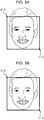
- the part result information is described with reference to FIGS. 5A and 5B .
- the part detail detector 35 may perform a standard process to detect the points of each part from the entire face, and a light-workload process to detect the points as an outline of the mouth.
- the part detail detector 35 detects 55 points identifying the outline of the face, the shape of the eyebrows, the outlines of the eyes, the shape of the nose, and the outline of the mouth as illustrated in FIG. 5A .
- the part detail detector 35 detects 14 points identifying the outline of the mouth as illustrated in FIG. 5B .
- the XY coordinates of each point are represented by values that are normalized with (0,0) as the coordinates of the top left corner of the face region and (1,1) as the coordinates of the bottom right corner of the face region.
- parts ID (partsID[0]-[55]) identifying each point is mapped to the XY coordinates (partsX, partsY) of the corresponding point.
- the user may incline his or her face, causing the points of each part of the face to be rotated (shifted) with respect to the entire image.
- the XY coordinates of each point are represented by values that are normalized in the face region. The positions of each point remain unchanged relative to the top left corner (origin) of the face region. The coordinate axis of each point is rotated in response to the inclination of the face region. If the position of each point with respect to the entire image is determined, a correction operation to incline the face in an opposite direction to the inclination of the face region is to be performed.
- the model selector 16 receives the male score and the adult score out of the attribute information output by the attribute determiner 34 under the control of the face recognition controller 31.
- the face recognition controller 31 performs the control process to cause the male score and the adult score output by the attribute determiner 34 to be supplied to the model selector 16 throughout a predetermined number of frames (15 frames, for example) starting with a frame from which the face detection processor 32 detects a new face.
- the model selector 16 determines whether the face of the user in the image is of a male, a female, or a child, on the basis of the male score and the adult score supplied by the attribute determiner 34.
- the model selector 16 selects one of a male model, a female model, and a child model as three-dimensional (3D) data that is used when the image generator 18 generates an image of an avatar.
- the model selector 16 then supplies the image generator 18 with model information indicating selection results. A process of the model selector 16 is described later with reference to a flowchart of FIG. 15 .
- the parameter generator 17 includes a face orientation correction processor 41, a filtering processor 42, a face orientation parameter calculator 43, a face position parameter calculator 44, an eye close ratio parameter calculator 45, a mouth open ratio parameter calculator 46, and a smiling face parameter calculator 47.
- the parameter generator 17 generates a variety of parameters serving as control data when the image generator 18 generates an avatar.
- the face orientation correction processor 41 receives an rotation angle of the face region (faceRoll, faceYaw) included in the face detection result information output by the face detection processor 32, and a posture (PoseRoll, PosePitch, PoseYaw) of the face region included in the face position information output by the part detector 33.
- a detection range of a rotation angle of the face region included in the face detection result information is set, and a detection range of the posture of the face region included in the face position information is set.
- the face detection result information is represented in the right-hand coordinate system, and the face position information is represented in the left-hand coordinate system.
- the face detection processor 32 is set to have about ⁇ 20 degrees as a detection range of a rolling motion of the face. No detection is performed in a pitching motion of the face.
- the face detection processor 32 is set to have about ⁇ 35 degrees as a detection range of a yawing motion of the face.
- the part detail detector 35 is set to have about ⁇ 35 degrees as a detection range of a rolling motion of the face, about ⁇ 20 degrees as a detection range of a pitching motion of the face, and about ⁇ 40 degrees as a detection range of a yawing motion of the face.
- the face orientation correction processor 41 performs a correction process to correct the face orientation to be output, based on time variations of the posture of the face region and time variations of the rotation angle of the face region.
- the rotation angle of the face region is insusceptible to time variations (stable) in the vicinity of the border of the detection range while the posture of the face region sharply varies with time due to a noise component in the vicinity of the border of the detection range.
- the face orientation correction processor 41 outputs the detection results of the posture of the face region at one-frame earlier frame in order to control the outputting of the noise component.
- the face orientation correction processor 41 then outputs the thus corrected face angle of the user.
- the filtering processor 42 ( FIG. 1 ) performs a filtering process on parameters output from the parameter calculators in the parameter generator 17 (the face orientation parameter calculator 43, the face position parameter calculator 44, the eye close ratio parameter calculator 45, the mouth open ratio parameter calculator 46, and the smiling face parameter calculator 47) in order to stabilize the parameters.
- the filtering process of the filtering processor 42 is described below with reference to FIGS. 7A and 7B .
- the filtering processor 42 is constructed as illustrated in a block diagram of FIG. 7A .
- the filtering processor 42 receives a parameter x t output from each parameter calculator and outputs a parameter y t .
- the parameter y t serves as control data when the image generator 18 generates the avatar.
- ⁇ represents an addition ratio between a parameter x t and a parameter y t-1
- the parameter y t-1 is an immediately preceding parameter output by the filtering processor 42 .
- the function determining the addition ratio ⁇ increases at a constant gradient within the variable diff from zero to the threshold value thresA, and flattens out at the maximum value max within the variable diff from the threshold value thresA to the threshold value thresB, and decreases from the threshold value thresB at a constant gradient reverse to the gradient within the variable diff from zero to the threshold value thresA. If the threshold value thresA and the threshold value thresB are equal to each other, the function determining the addition ratio ⁇ has a mountain shape as will be described later.
- the maximum value max, the threshold value thresA, and the threshold value thresB are set in the filtering processor 42.
- the filtering processor 42 performs the filtering process on the parameters input from the parameter calculators in accordance with the addition ratio ⁇ determined from the variable diff and the above-described equation (1).
- the filtering processor 42 then supplies a filtering processed parameter to the image generator 18.
- the face orientation parameter calculator 43 calculates a parameter controlling the face angle of the avatar generated by the image generator 18, in accordance with the face angle of the user corrected by the face orientation correction processor 41.
- the face orientation correction processor 41 performs the correction process in the right-hand coordinate system while the image generator 18 performs the process thereof in the left-hand coordinate system. Referring to FIG. 8A , the right-hand coordinate system and the left-hand coordinate system are opposite each other in the rolling motion and the yawing motion.
- the face orientation parameter calculator 43 thus inverts the signs of the directions of the rolling motion and the yawing motion of the face angle of the user corrected by the face orientation correction processor 41.
- the parameter of the face angle of the avatar output by the face orientation parameter calculator 43 is supplied to the filtering processor 42.
- the filtering processor 42 performs the filtering process on the parameter as illustrated in FIG. 7A .
- the face position parameter calculator 44 calculates the parameter controlling the face position of the avatar generated by the image generator 18, in accordance with the reference point, the horizontal width, and the vertical length (faceX, faceY, faceW, faceH) included in the face detection result information output by the filtering processor 42.
- the top left corner of the face region is set as the reference point in the face detection result information output by the face detection processor 32 as illustrated in FIG. 3 while the center of the face region is set as the reference point (denoted by the letter x in FIG. 9A ) by the image generator 18 as illustrated in FIG. 9A .
- the face recognition controller 31 performs the process thereof in the coordinate system ( FIG. 3 ) with the top left corner of the entire image serving as the origin (0,0).
- the image generator 18 performs the process thereof with the center of the entire image serving as the origin (0,0) as illustrated in FIG. 9A .
- the face position parameter calculator 44 calculates the function illustrated in FIG. 2B , i.e., the following equation (2), thereby determining, as parameters of the face position, coordinates of the center point of the face region in the coordinate system having the center of the entire image as the origin.
- x out x in + w in 2.0 ⁇ 2.0 ⁇ 1.0
- y out y in + h in 2.0 ⁇ 2.0 ⁇ 1.0
- x in and y in represent reference points of the face region input to the face position parameter calculator 44, i.e., XY coordinates (faceX, faceY) of the reference points of the face region included in the face detection result information output by the face detection processor 32.
- w in and h in represent respectively the horizontal width and vertical length (faceW, faceH) of the face region input to the face position parameter calculator 44.
- x out and y out represent parameters (XY coordinates of points represented by the letter x's in FIG. 9A ) of the face region output by the face position parameter calculator 44.
- x in , y in , w in , and h in are values in a normalized coordinate system with the top left corner of the entire image being the origin (0,0) and fall within a range of 0.0 to 0.1
- x out and y out are values in a normalized coordinate system with the center of the entire image being the origin (0,0) and fall within a range of from -0.1 to 0.1.
- the parameter of the face position output by the face position parameter calculator 44 is supplied to the filtering processor 42.
- the filtering processor 42 then performs the filtering process on the parameter as illustrated in FIG. 7A .
- the eye close ratio parameter calculator 45 calculates a parameter controlling the right eye close ratio and the left eye close ratio of the avatar generated by the image generator 18, based on the right eye open score and the left eye open score of the user determined by the attribute determiner 34.
- the eye close ratio parameter calculator 45 calculates the following equation (3) based on a sigmoid function.
- the eye close ratio parameter calculator 45 thus calculates the parameters of the right eye close ratio and the left eye close ratio of the avatar from the open scores of the right eye and the left eye of the user.
- y gain ⁇ e ⁇ grad ⁇ x ⁇ ofs 1 + e ⁇ grad ⁇ x ⁇ ofs ⁇ gain ⁇ 1 2
- y is a close ratio
- x is an open score
- ofs is a value for offsetting the initial value of the open score
- grad is a value setting a mildness of the sigmoid function.
- the value calculated by the sigmoid function ranges from 0.0 to 1.0
- gain is an amplification factor according to which the value is amplified with respect to a center value (0.5).
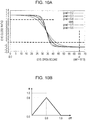
- FIG. 10A illustrates the relationship between the close ratio y and the open score x that are determined by calculating the sigmoid function using a plurality of grad values (0.2 - 0.6) with an amplification factor gain of 1.4.
- p is a value that can be set as a maximum value for the open scores of the right eye and the left eye of the user.
- a maximum value and a minimum value can be set for the parameter of the close ratio. Referring to FIG. 10A , 1.0 is set for the maximum value and 0.0 is set for the minimum value.
- the open scores of the right eye and the left eye of the user determined by the attribute determiner 34 are converted into the parameters of the close ratios of the right eye and the left eye of the avatar to be generated by the image generator 18, using the sigmoid function.
- individual variations in the size of the eye with the eye fully opened are reduced, and the effect of the face orientation on the close ratio and the open ratio of the eye is controlled. For example, a narrow-eyed person tends to have a low open score, and a person, when looking down, has a low open score. If the parameter of the close ratio is determined using the sigmoid function, that tendency is controlled.
- the use of the sigmoid function permits not only one eye in an open state and the other eye in a closed state (winking eyes) to be represented but also half-closed eyes to be naturally represented.
- the opening and the closing of the eyes can be represented such that the motion of the eyelids are mild at the start of eye closing or eye opening.
- a function causing the parameter of the close ratio to change linearly between a maximum value and a minimum value may be used to represent the narrowed eyes.
- the use of the sigmoid function expresses the opening and closing of the eyes even more closer to the actual motion of the human.
- the parameters of the close ratios of the right eye and the left eye output by the eye close ratio parameter calculator 45 are supplied to the filtering processor 42.
- the filtering processor 42 performs the filtering process on the parameters as illustrated in FIG. 7A .
- the mouth open ratio parameter calculator 46 calculates a parameter controlling an open ratio of the mouth of the avatar to be generated by the image generator 18, based on 14 points identifying the outline of the mouth of the user detected by the part detail detector 35.
- the mouth open ratio parameter calculator 46 performs two evaluation processes to determine on the basis of each point identifying the outline of the mouth of the user whether detection results of the outline of the mouth are correct.
- a distance in a vertical direction between predetermined points is used.
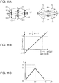
- the mouth open ratio parameter calculator 46 determines vertical distances (R1, R2, and R3) between any two adjacent points of the four right points other than the rightmost point, out of the 14 points identifying the outline of the mouth of the user as illustrated in a left portion of FIG. 11A .
- the mouth open ratio parameter calculator 46 determines vertical distances (L1, L2, and L3) between any two adjacent points of the four left points other than the leftmost point and vertical distances (C1, C2, and C3) between any two adjacent points of the four center points. If all the vertical distances thus determined are positive values, the mouth open ratio parameter calculator 46 determines that the detection results of the outline of the mouth are correct.
- a shape of a rectangular region having two predetermined points as opposing corners is used.
- the mouth open ratio parameter calculator 46 determines shapes of rectangular regions (T1 and T2) having as opposing corners any two adjacent points of lower three points in the upper lip, out of the 14 points defining the outline of the mouth of the user as illustrated in a right portion of FIG. 11A .
- the mouth open ratio parameter calculator 46 determines shapes of rectangular regions (T3 and T4) having as opposing corners any two adjacent points of upper three points in the lower lip, out of the 14 points defining the outline of the mouth of the user. If all the rectangular regions thus determined are horizontally elongated, the mouth open ratio parameter calculator 46 determines that the detection results of the outline of the mouth are correct.
- the mouth open ratio parameter calculator 46 calculates the parameter of the open ratio of the avatar to be generated by the image generator 18, based on the 14 points identifying the outline of the mouth of the user detected by the part detail detector 35. If the detection results of the outline of the mouth are correct, the openness of the mouth of the user is reflected in the mouth of the avatar.
- the mouth open ratio parameter calculator 46 thus calculates the mount open ratio as a parameter.
- x is a vertical distance (height) as an input value
- y is a parameter as the mouth open ratio
- p is a value setting a maximum vertical distance (height) as the input value.
- the parameter indicating the mouth open ratio is set in the standard state with the mouth fully opened, and linearly mapped to the height.
- a distance for calculating the parameter indicating the mouth open ratio may be determined from a distance between the center of the mouth and the center of the nose. In such a case, a value resulting from multiplying the distance between the center of the mouth and the center of the nose multiplied by 0.4 is used as the above-described input value (height).
- the parameter indicating the mouth open ratio output by the mouth open ratio parameter calculator 46 is supplied to the filtering processor 42, and the filtering process illustrated in FIG. 7A is then performed on the parameter.
- the smiling face parameter calculator 47 calculates a parameter controlling a smile ratio of the avatar, generated by the image generator 18, based on the smile score included in the attribute information output by the attribute determiner 34.
- the smile score detected by the attribute determiner 34 is a value ranging from 0 to 70.
- x represents a smile score as an input value
- y represents a parameter as an output value indicating a smile ratio.
- the parameter indicating the smile ratio output by the smiling face parameter calculator 47 is supplied to the filtering processor 42.
- the filtering processor 42 performs the filtering process illustrated in FIG. 7A .
- the parameters generated by the parameter calculators in the parameter generator 17 are supplied to the image generator 18 ( FIG. 1 ) and the image generator 18 generates the avatar based on the parameters.
- the image generator 18 includes a three-dimensional (3D) data manager 51, a shader manager 52, a renderer 53, and a synthesis processor 54.
- the 3D data manager 51 manages 3D data of the avatar, i.e., manages a database (not illustrated) storing the 3D data of male, female, and child avatars.
- the 3D data manager 51 receives from the model selector 16 the model information (information indicating determination results as to whether a face in an image is of a male, a female, or a child).
- the 3D data manager 51 reads the 3D data of the avatar responsive to the model information from the database, and then supplies the read 3D data to the renderer 53.
- the 3D data manager 51 manages a variety of data that is used to perform a geometry process to convert coordinates of a 3D model into an output (two-dimensional) image and a texture process to glue a texture for the purpose of imparting texture to the surface of the 3D model.
- the 3D data manager 51 then supplies the variety of data to the renderer 53.
- the shader manager 52 manages a shading process.
- the shader manager 52 performs a computing operation to shade the 3D data with a predetermined light source (illumination).
- the shader manager 52 supplies the computation results of the shading process to the renderer 53.
- the renderer 53 performs a rendering process by morphing the 3D data supplied by the 3D data manager 51, in accordance with expression parameters output by the parameter calculators in the parameter generator 17 (the parameters indicating the eye open ratio of each of the right eye and the left eye of the avatar, the parameter indicating the smile ratio of the avatar, and the parameter indicating the mouth open ratio of the avatar).
- the 3D data manager 51 supplies to the renderer 53 the 3D data of a plurality of basic expressions for a single model.
- the 3D data manager 51 supplies to the renderer 53 expressionless 3D data, 3D data with the right eye closed, 3D data with the left eye closed, 3D data of a smiling face, and 3D data with the mouth opened for each of a male model, a female model, and a child model as illustrated in FIG. 13 .
- P reye_close (x,y, z) represents a predetermined apex of the 3D data with the right eye closed
- W reye_close represents a parameter indicating the eye close ratio of the right eye
- P leye_close (x,y,z) represents a predetermined apex of the 3D data with the left eye closed
- W leye_close represents a parameter indicating the eye close ratio of the left eye
- P mouth_open (x,y, z) represents a predetermined apex of the 3D data with the mouth opened
- W mouth_open represents a parameter indicating the mouth open ratio of the avatar
- P smile (x,y,z) represents a predetermined apex of the smiling 3D data
- W smile represents a parameter indicating the smile ratio of the avatar
- P normal (x,y,z) represents a predetermined apex of the expressionless 3D data.
- the renderer 53 performs the rendering process using the morphed 3D data that results from weighted summing the basic expression 3D data with the corresponding parameters.
- the renderer 53 thus generates an image of the face of the avatar.
- the renderer 53 also performs the rendering process by setting an orientation of the morphed 3D data such that the image of the avatar is oriented in accordance with the parameter indicating the face angle of the avatar output by the face orientation parameter calculator 43.
- the synthesis processor 54 receives the image of the face of the avatar rendered by the renderer 53, and the parameter controlling the face position of the avatar from the face position parameter calculator 44.
- the synthesis processor 54 also receives from the camera input unit 14 the image captured by the camera 12.
- the synthesis processor 54 performs a synthesis process to replace the face of the user with the avatar.
- the face of the avatar supplied by the renderer 53 is overlaid at a position of the face of the user in the image captured by the camera 12 (the input image illustrated in FIG. 2A ) in accordance with the parameter controlling the face of the avatar.
- the synthesis processor 54 supplies to the display 13 the image obtained through the synthesis process (the output image as illustrated in FIG. 2B ). The image is thus displayed on the display 13.
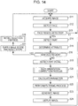
- FIG. 14 is a flowchart illustrating an image processing process performed by the image processing apparatus 11 illustrated in FIG. 1 .
- the image processing apparatus 11 starts the process in response to a user operation.
- the camera input unit 14 acquires an image input by the camera 12.
- the camera input unit 14 decodes the image (raw data) supplied by the camera 12 with the decoder 22 thereof, and then supplies the decoded data to the face detection processor 32 in the face recognizer 15. Processing proceeds to step S12.
- step S12 the face detection processor 32 performs the face detection process to detect the face region of the face of the user from the image supplied by the camera input unit 14 in step S11. Upon detecting the face region, the face detection processor 32 outputs the face detection result information.
- step S12 Processing proceeds from step S12 to step S13.
- the face recognition controller 31 determines whether the face detection processor 32 has detected the face region in step S12, i.e., determines whether the face detection processor 32 has output the face detection result information.
- step S13 determines in step S13 that the face detection processor 32 has not detected the face region. If the face recognition controller 31 determines in step S13 that the face detection processor 32 has not detected the face region, processing returns to step S11. Steps S11 and step S12 are repeated. If the face recognition controller 31 determines in step S13 that the face detection processor 32 has detected the face region, processing proceeds to step S14.
- step S14 the part detector 33 detects a part of the face from the face region indicated by the face detection result information output by the face detection processor 32 in step S12.
- the part detector 33 outputs the part information indicating coordinates of the center of each of the parts including the right eye, the left eye, the nose, and the mouth, and the face position information indicating the position and the posture of the face determined from the parts. Processing proceeds to step S15.
- step S15 the attribute determiner 34 determines the attribute of the face of the user within the face region based on the part information output by the part detector 33 in step S14, and outputs the attribute information indicating the determination results.
- the attribute information includes the male score, and the adult score.
- the face recognition controller 31 determines whether the face region as a current process target is a new face region.
- the image processing apparatus 11 processes the image input from the camera 12 on a per frame basis. If the number of frames from a frame from which the face region as the current process target was first detected to an immediately preceding frame detected in step S12 is 15 or less, the face recognition controller 31 determines that the face region as the current process target is a new target. If the number of frames is more than 15, the face recognition controller 31 determines that the face region as the current process target is not a new target.
- step S16 If the face recognition controller 31 determines in step S16 that the face region as the current process target is a new target, processing proceeds to step S17.
- step S17 the face recognition controller 31 supplies to the model selector 16 the male score and the adult score included in the attribute information output by the attribute determiner 34 in step S15. Processing proceeds to step S18.
- step S18 the model selector 16 performs a model selection process based on the male score and the adult score supplied by the face recognition controller 31 in step S17.
- the model selector 16 selects one of the male model, the female model, and the child model as the 3D data of the avatar to replace the face of the user in the face region.
- the model selection process is described later with reference to FIG. 15 .
- processing returns to step S11. The same process as described above is then repeated on a next frame.
- step S16 If the face recognition controller 31 determines in step S16 that the face region as the current process target is not a new target, processing proceeds to step S19.
- step S19 the part detail detector 35 detects a point (see FIGS. 5A and 5B ) identifying in detail the part of the face of the user in the face region.
- the part detail detector 35 outputs the part result information. Processing proceeds to step S20.
- step S20 the face orientation correction processor 41 performs a face orientation correction process to correct the orientation of the face of the user in the face region.
- the face orientation correction process is described later with reference to FIG. 16 . Subsequent to the face orientation correction process, processing proceeds to step S21.
- each parameter calculator in the parameter generator 17 calculates the corresponding parameter. More specifically, the face orientation parameter calculator 43 calculates the parameter indicating the face angle of the avatar from the face angle of the user output by the face orientation correction processor 41 in step S20. The face position parameter calculator 44 calculates the parameter indicating the face position of the avatar from the face detection result information output by the face recognition controller 31 in step S12.
- the eye close ratio parameter calculator 45 calculates the eye close ratios of the right eye and the left eye of the avatar from the eye open scores of the right eye and the left eye of the user determined by the attribute determiner 34 in step S15.
- the mouth open ratio parameter calculator 46 calculates the parameter indicating the mouth open ratio of the avatar from the 14 points identifying the outline of the mouth of the user detected by the part detail detector 35 in step S19.
- the smiling face parameter calculator 47 calculates the parameter indicating the smile ratio of the avatar from the smile score included in the attribute information output by the attribute determiner 34 in step S15.
- step S22 the filtering processor 42 performs the filtering process on the parameters respectively output by the face orientation parameter calculator 43, the face position parameter calculator 44, the eye close ratio parameter calculator 45, the mouth open ratio parameter calculator 46, and the smiling face parameter calculator 47 to stabilize the parameters.
- the filtering processor 42 then outputs the parameters stabilized through the filtering process to the image generator 18.
- step S23 the image generator 18 performs an image generation process to generate an image to be displayed on the display 13.
- the 3D data manager 51 in the image generator 18 supplies the renderer 53 with the 3D data of the five expressions of the avatar to replace the face of the user in the face region in accordance with the model information output by the model selector 16 in the model selection process in step S18.
- the renderer 53 generates the image of the avatar by morphing the 3D data of the five expressions in response to the parameters supplied by the filtering processor 42.
- the synthesis processor 54 synthesizes the image of the avatar rendered by the renderer 53 at the position of the face of the user in the image captured by the camera 12. The synthesis processor 54 thus generates the image with the face of the user replaced with the avatar. Subsequent to the image generation process, processing proceeds to step S24.
- step S24 the image generator 18 supplies the image generated in step S23 to the display 13 and the display 13 displays the image. Processing returns to step S11. The same process as the one discussed above is repeated on a next frame.
- the image processing apparatus 11 conserves the user's time for specifying the avatar.
- the user specifies an avatar matching the attribute of the user in order to display the avatar in place of the user's face.
- the image processing apparatus 11 conserves such time, and causes the avatar matching the attribute of the user to be displayed on the display 13 substantially at the same time as when the image of the user is captured by the camera 12. The user can thus feel togetherness with the avatar.
- the image processing apparatus 11 is used in a virtual space such as in game playing or chat room, the user finds more empathy for the virtual space.
- each parameter is filtering processed, the motion of the avatar becomes smooth.
- the user feels more togetherness with the avatar. For example, an error of several pixels is tolerated in the face detection process for detecting the face in the image. If the face remains motionless (or is slowly moving), the avatar may vibrate in position (or fluctuate in at high speed within a slight swing) because of the error.
- the filtering process prevents the avatar from vibrating, and frees the user (who views an image or plays a game in the virtual space) from a sense of discomfort otherwise caused by such a vibration.
- the addition ratio ⁇ is dynamically determined based on the variable diff between the current input value and the immediately preceding input value.
- the filtering process appropriate for both the face remaining motionless (or slowly moving) and the face moving rapidly is performed. More specifically, when the face remains motionless, the value of the addition ratio ⁇ is set to be small (i.e., a weight of an immediately preceding output value (parameter y t-1 ) is set to be large and a weight of an input value (parameter x t ) is set be small) in order to stabilize the position of the face.
- the value of the addition ratio ⁇ is set to be large in order to increase follow-up performance responsive to the movement of the face.
- the avatar is thus displayed at a more accurate position. If the face moves rapidly, an error involved in the face detection process becomes relatively small with respect to the travel distance of the face. The vibration of the avatar described above is less noticeable.
- the filtering process thus provides an intuitive visual effect to the user.
- the image processing apparatus 11 performing the image processing process provides the user with a new experience in virtual communication and content-rich communications in a virtual space.
- FIG. 15 is a flowchart illustrating the model selection process in step S18 of FIG. 14 .
- step S31 the model selector 16 initializes count values used in the model selection process. Used in the model selection process are a frame count value indicating the number of processed frames, a child count value indicating the number of times of face determined as being a child, a male count value indicating the number of times of face determined as being a male, and a female count value indicating the number of times of face determined as being a female.
- the model selector 16 initializes these count values (to zero, for example). Processing proceeds to step S32.
- step S32 the model selector 16 determines whether the face of the user in the face region is of a child, based on the adult score supplied by the face recognition controller 31 in step S17 of FIG. 14 . For example, if the adult score is lower than a predetermined threshold (for example, an intermediate value between the maximum value and the minimum value of the adult score), the model selector 16 determines that the face of the user is of a child. If the adult score is equal to or higher than the predetermined threshold value, the model selector 16 determines that the face of the user in the face region is of an adult.
- a predetermined threshold for example, an intermediate value between the maximum value and the minimum value of the adult score
- step S32 determines in step S32 that the face of the user in the face region is of a child
- processing proceeds to step S33.
- the model selector 16 increments the child count value by one.
- step S32 determines in step S32 that the face of the user in the face region is not of a child, processing proceeds to step S34.
- step S34 the model selector 16 determines whether the face of the user in the face region is of a male, based on the male score supplied by the face recognition controller 31. For example, if the male score is equal to or higher than a predetermined threshold (for example, an intermediate value between the maximum value and the minimum value of the adult score), the model selector 16 determines that the face of the user is of a male. If the male score is lower than the predetermined threshold value, the model selector 16 determines that the face of the user in the face region is not of a male.
- a predetermined threshold for example, an intermediate value between the maximum value and the minimum value of the adult score
- step S34 determines in step S34 that the face of the user in the face region is of a male
- processing proceeds to step S35.
- the model selector 16 increments the male count value by one.
- step S36 determines in step S34 that the face of the user in the face region is not of a male
- step S36 increments the female count value by one.
- step S37 The model selector 16 determines whether the frame count value is equal to or higher than a predetermined count set for the selection of the model (for example, 15).
- step S37 determines in step S37 that the frame count value is not equal to or higher than the predetermined count set for the selection of the model (lower than the predetermined count)
- step S38 the model selector 16 increments the frame count value by one. Processing returns to step S32. The same process as described above is repeated on a next frame.
- step S37 If the model selector 16 determines in step S37 that the frame count value is equal to or higher than the predetermined count set for the selection of the model, processing proceeds to step S39.
- step S39 the model selector 16 references the child count value, the male count value, and the female count value in order to select as a model of the 3D data of the avatar one of the child, the male, and the female having the highest number of determinations (the highest count value).
- step S39 Processing proceeds from step S39 to step S40.
- the model selector 16 supplies to the image generator 18 information indicating the selection results in step S39. Processing thus ends.
- the model selector 16 selects a model based on a plurality of determination results, thereby increasing an accuracy at which a model matching the user is selected.
- the attribute determiner 34 can erroneously recognize the model depending on the effect of illumination and the expression of the user (for example, a male is mistaken for a female or vice versa when the male is smiling), and an unstable score can be output. If the model selector 16 uses a plurality of determination results even in such a case, the effect of the erroneous recognition made by the attribute determiner 34 is controlled.
- FIG. 16 is a flowchart of the face orientation correction process in step S20 of FIG. 14 .
- step S51 the face orientation correction processor 41 acquires the rotation angle (faceRoll, face Yaw) of the face region included in the face detection result information output by the face detection processor 32 when the face region is detected in step S12 of FIG. 14 , and also acquires the posture (PoseRoll, PoseYaw) of the face region included in the face position information output by the part detector 33 in step S14.
- step S51 The face orientation correction processor 41 determines whether the orientation of the user face in the face region is in the vicinity of the border of the detection range.
- the vicinity of the border of the detection range is defined by a ratio to the detection range in the face detection result information.
- the ratio defining the vicinity of the border of the detection range is pre-set in the face orientation correction processor 41.
- the ratio of the vicinity of the border of the detection range may be set to be 87.5%. If the rotation angle (faceRoll, faceYaw) of the face region is larger than 87.5% of the detection range in the face detection result information, it is determined that the orientation of the face of the user is in the vicinity of the border of the detection range.
- the detection range of the rolling motion of the face in the face detection result information may be about ⁇ 20 degrees as illustrated in FIG. 6 . If the rotation angle of the face region (faceRoll) is greater than about ⁇ 17.5, the face orientation correction processor 41 determines that the orientation of the face of the user is in the vicinity of the border of the detection range. Similarly, the detection range of the yawing motion of the face in the face detection result information may be about ⁇ 35 degrees. If the rotation angle of the face region (faceYaw) is greater than about ⁇ 30.6, the face orientation correction processor 41 determines that the orientation of the face of the user is in the vicinity of the border of the detection range.
- the face orientation correction processor 41 determines whether the orientation of the face of the user is in the vicinity of the border of the detection range in each of the rolling motion and the yawing motion of the face. If the face detection result information for the pitching motion is also available, the face orientation correction processor 41 determines in a similar process whether the orientation of the face of the user is in the vicinity of the border of the detection range.
- the vicinity of the border of the detection range is defined by the ratio to the detection range in this way.
- the vicinity of the border of the detection range may be defined directly by an angle (for example, the vicinity of the border of the detection range may be defined by 3 degrees from the border of the detection range).
- the detection range of the orientation of the face of the user is not limited to those listed in FIG. 6 , and may be different depending on performance of a detector in use (or a face detection dictionary used by the detector).
- a detector may have detection ranges of ⁇ 40 degrees for the rolling motion, ⁇ 20 degrees for the pitching motion, and ⁇ 45 degrees for the yawing motion, and another detector may have detection ranges of ⁇ 90 degrees for the rolling motion, ⁇ 45 degrees for the pitching motion, and ⁇ 45 degrees for the yawing motion.
- step S53 If the face orientation correction processor 41 determines that the orientation of the face of the user in the face region is in the vicinity of the border of the detection range, processing proceeds to step S53.
- the face orientation correction processor 41 calculates time variations of the rotation angle and the posture of the face region.
- ) is determined, where tgtIn t represents the current face angle and tgtIn t-1 represents the face angle of the immediately preceding frame. Furthermore, the time variation of the posture of the current face region diff pos (
- step S54 If the face orientation correction processor 41 determines in step S54 that the difference is larger than the predetermined threshold value, processing proceeds to step S55.
- the face orientation correction processor 41 outputs the face angle (posIn t-1 ) of the immediately preceding frame, and the face orientation correction process thus ends. Since a large time variation is caused by noise, the face orientation correction processor 41 outputs the face angle (posIn t-1 ) of the immediately preceding frame in place of the current face angle (posIn t ) suffering from such a large variation in order to control the vibration of the avatar.
- the face orientation correction processor 41 may determine in step S52 that the orientation of the face of the user in the face region is not in the vicinity of the border of the detection range (for example, within 87.5% of the detection range as described above), or the face orientation correction processor 41 may determine in step S54 that the difference between the time variations is not larger than the predetermined threshold value (the time variation is smaller than the predetermined threshold value). In such a case, processing proceeds to step S56.
- step S56 the face orientation correction processor 41 outputs the face angle (posIn t ) of the current frame.
- the face orientation correction process thus ends.
- the orientation of the face of the user is not in the vicinity of the border of the detection range, and it is determined that an accurate face angle is detected.
- the time variation is small, and no noise is likely to have occurred.
- the face orientation correction processor 41 outputs the face angle (posIn t ) of the current frame.
- the face orientation correction process prevents the detection results from being varied at irregular intervals even if the orientation of the face of the user is in the vicinity of the border of the detection range.
- the face of the avatar is free from unnatural vibration in the vicinity of the border of the detection range. The avatar can thus accurately follow the movement of the face of the user.
- the expression of the avatar is synthesized using the expression parameters discussed with reference to FIG. 13 .
- Many more parameters may be used as parameters for the synthesis of the expression of the avatar in addition to those expression parameters.
- FIG. 17 illustrates an example of parameters that can be used in the expression synthesis.
- the types of parameters available in the expression synthesis include emotional parameters, part parameters, and viseme parameters.
- the emotional parameters include a sadness parameter and an anger parameter determined using the attribute determiner 34, in addition to a smiling parameter determined from the smile score included in the attribute information output by the attribute determiner 34.
- the part parameters include a blinking parameter, an eyebrow parameter, an eyeball parameter, and a mouth closing and opening parameter determined from 55 points output by the part detail detector 35 (see FIG. 5A ).
- the viseme parameters included a viseme /a/ parameter, a viseme /i/ parameter, a viseme /u/ parameter, a viseme /e/ parameter, a viseme /o/ parameter, and a viseme /n/ parameter determined from a vowel determination score output by the vowel viseme determiner 62 of FIGS. 18A and 18B to be discussed later.
- the motion of the mouth of the user is faithfully reflected in the avatar by synthesizing the mouth shape of the avatar based on these viseme parameters.
- a mouth shape synthesis process for synthesizing the mouth shape of the avatar based on the viseme parameter is described below with reference to FIGS. 18A and 18B .
- the image processing apparatus 11 stores the basic mouth shape of each vowel to synthesize a mouth shape. More specifically, the basic mouth shapes for pronouncing a vowel /a/, a vowel /i/, a vowel /u/, a vowel /e/, a vowel /o/, and a vowel /n/ are stored as illustrated in FIG. 18A .
- the pronunciation /n/ includes a pronunciation /p/.
- a mouth shape is synthesized based on a viseme parameter W a of the vowel /a/, a viseme parameter W i of the vowel /i/, a viseme parameter W u of the vowel /u/, a viseme parameter W e of the vowel /e/, a viseme parameter W o of the vowel /o/, and a viseme parameter V n of the vowel /n/ as weights for the respective basic shapes.
- the motion of the mouth of the user is even more faithfully reflected in the avatar.
- the basic shape for pronouncing the vowel /e/ is generated by synthesizing the basic shape for pronouncing the vowel /i/ and the basic shape for pronouncing the vowel /a/.
- the basic shape for pronouncing the vowel /o/ is generated by synthesizing the basic shape for pronouncing the vowel /u/ and the basic shape for pronouncing the vowel /a/.
- the mouth shape may be synthesized with the viseme parameter W a of the vowel /a/, the viseme parameter W i of the vowel /i/, the viseme parameter W u of the vowel /u/, and the viseme parameter V n of the vowel /n/ serving as the weights of the basic shapes.
- the motion of the mouth of the user is faithfully reflected in the avatar.
- the viseme parameters are determined from the points identifying the outline of the mouth detected by the part detail detector 35.
- the viseme parameters may also be determined through voice recognition.
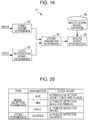
- FIG. 19 is a block diagram illustrating a mouth shape synthesis processor 61 synthesizing the mouth shape of the avatar on the basis of the viseme parameter.
- the mouth shape synthesis processor 61 illustrated in FIG. 19 includes a vowel viseme determiner 62, a voice recognition vowel determiner 63, a viseme parameter determiner 64, a mouth shape model database 65, and a mouth shape synthesizer 66.
- the vowel viseme determiner 62 receives the points identifying the outline of the mouth of the user detected from the image by the part detail detector 35. The vowel viseme determiner 62 then determines the shape of the mouth from the points. The vowel viseme determiner 62 then supplies to the viseme parameter determiner 64 a vowel determination score indicating the ratio of each vowel, at which the shape of the mouth is represented by a combination of the vowel /a/, the vowel /u/, the vowel /e/, the vowel /o/, and the vowel /n/ illustrated in FIGS. 18A and 18B .
- the voice recognition vowel determiner 63 receives a voice input by a voice input device (not illustrated) such as a microphone.
- the voice recognition vowel determiner 63 performs a voice recognition process to the voice, thereby determining a vowel pronounced by the user, and supplying the vowel determination score to the viseme parameter determiner 64.
- the viseme parameter determiner 64 determines as a viseme parameter the mean value of the vowel determination score from the vowel viseme determiner 62 and the vowel determination score from the voice recognition vowel determiner 63. The viseme parameter determiner 64 then supplies the viseme parameter to the mouth shape synthesizer 66. If the voice recognition vowel determiner 63 is not used, the vowel determination score from the vowel viseme determiner 62 serves as a viseme parameter.
- the mouth shape model database 65 stores the 3D data of the basic mouth shape for each vowel.
- the mouth shape synthesizer 66 weighted sums the apexes of the 3D data for the basic mouth shapes with the respective viseme parameters of the vowels, thereby synthesizing the mouth shape.
- the mouth shape synthesis processor 61 synthesizes the mouth shape of the avatar, and the renderer 53 renders the 3D data of the mouth shape.
- the shape of the mouth of the avatar is thus more closely approximated to the shape of the mouth of the user.
- the generated avatar may speak in a gesture more similar to a gesture with which the user speaks. Since the mouth shape of the avatar is closely approximated to the mouth shape of the user, the user feels togetherness with the avatar. The user feels more empathy for the image displayed on the display 13.
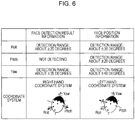
- the image processing apparatus 11 performs the process based on parameters listed in FIG. 20.
- FIG. 20 lists the parameters to be used by the image processing apparatus 11.
- Model selection parameters include an age parameter, a sex parameter, and a race parameter. Other parameters include glass parameter. The parameters are determined based on the attribute determined by the attribute determiner 34.
- the age parameter indicates a parameter indicating an age bracket having a face displayed in the image (age brackets delineated by age, such as age brackets of teens, twenties, thirties, or roughly delineated age groups, such as children (0-teens), adults (twenties - fifties), elder (sixties or older)).
- the attribute determiner 34 determines the attribute of the face displayed in the image, and outputs a score representing a numerical rating of the degree of adult, the degree of child, and the degree of elder. Depending on the score, the age parameter is determined.
- the 3D data manager 51 supplies the 3D data of the avatar based on the age parameter to the renderer 53. An avatar closer to the user's age than an avatar simply sorted as of adult or child is displayed.
- the sex parameter indicates sex of the face (male or female) displayed in the image.
- the race parameter indicates a race of the face displayed in the image (such as white, black, and yellow races).
- the attribute determiner 34 determines the attribute of the face displayed in the image, and outputs a score representing a numerical rating of the degree of each race.
- the race parameter is determined based on the score.
- the 3D data manager 51 supplies to the renderer 53 a race texture and 3D data of the race parameter. An avatar more like the face of the user is thus displayed.
- the glass parameter indicates whether glasses are worn on the face of the displayed image.
- the attribute determiner 34 outputs a score representing a numerical rating of the degree of whether glasses are worn on the face of the displayed image.
- the glass parameter is determined on the score. If the glass parameter indicates that glasses are worn, the 3D data manager 51 supplies the 3D data of glasses to the renderer 53. An avatar wearing the glasses is automatically displayed.
- a model is automatically selected in accordance with the attribute of the user (child, male, female). If a user is identified by performing precisely the face recognition on the user, the face of the user may be replaced with an avatar pre-registered by the user. If the user is individually identified through the face recognition, the user may be free from specifying the user's own avatar. The user can thus enjoy in a seamless fashion a real space and a virtual space (space of the image displayed on the display 13).
- the attribute of the user determined by the image processing apparatus 11 does not necessarily include all the above-described parameters. It is sufficient if the attribute includes one of the above-described parameters.
- the parameter generator 17 of FIG. 1 outputs a parameter that is obtained when the filtering processor 42 performs the filtering processing the parameter calculated by each parameter calculator. Even if an unstable variation is contained in the parameter calculated by each parameter calculator, the filtering processor 42 removes the unstable variation from the parameter. A stable parameter is thus output.
- the avatar generated by the image generator 18 smoothly moves.
- the filtering processor 42 is constructed of a one-state filter as illustrated in FIG. 7A .
- An error may occur in the calculation performed by a parameter calculator in the parameter generator 17 and a parameter output by the parameter calculator may suffer from a sharp variation. It is difficult to remove such a sharp variation.
- the filtering processor 42 is constructed of a multi-stage filter, such a sharp variation contained in the parameter can be reduced. If the filtering processor 42 constructed of a multi-stage filter is used, a filtering process takes time. The behavior of the avatar generated by the image generator 18 is subject to a delay with respect to the behavior of the user.
- a filtering process remove the effect of an error and be free from a delay in the behavior of an avatar even if the error occurs in the calculation of a parameter calculator in the parameter generator 17 and the parameter output by the parameter calculator suffers from a sharp variation.
- the parameters output by the parameter calculators in the parameter generator 17 are estimation results of the state of the face of the user based on the detection result of the face recognizer 15 (the orientation of the face, the position of the face, the close and open ratio of the eye, the close and open ratio of the mouth, and the degree of smile).
- a parameter as a process target in the filtering process is also referred to as a state estimation result value.
- FIG. 21 illustrates three types of normal distribution.
- the abscissa represents a value of state estimation result
- the ordinate represents probability.
- a normal distribution curve f(x) is an error distribution of values of past state estimation results centered on a state estimation result value u f as a target of the filtering process.
- a normal distribution curve r(x) is a likelihood distribution of a predictive output value u r centered on the predictive output value u r . The predictive output value u r of the filtering process with a state estimation result value u f as a process target is predicted from the filtering process result heretofore obtained.
- a normal distribution curve p(x) is a normal distribution resulting from multiplying the normal distribution curve f(x) and the normal distribution curve r(x) and is expressed in the following equation (5):
- Equation (5) is re-organized with a state estimation result value x as a variable
- u p is an expected value of the normal distribution curve p(x) and is an output value outputted in the filtering process
- ⁇ p is a standard deviation of the normal distribution curve p(x)
- K o is a normalized term (constant) of the normal distribution curve p(x).
- a reliability of the state estimation result value u f as a process target of the filtering process is evaluated, and the evaluated reliability is reflected in the variance ⁇ f 2 of the error distribution and the variance ⁇ r 2 of the likelihood distribution.
- the filtering process that outputs adaptively a value in a relationship between the state estimation result value u f and a predictive output value u r in response to the reliability of the state estimation result value u f is thus performed.
- the ratio of the variance ⁇ f 2 of the error distribution to the variance ⁇ r 2 of the likelihood distribution is a relative value. It is sufficient if the evaluated reliability of the state estimation result value u f is reflected in one of the variance ⁇ f 2 and the variance ⁇ r 2 .
- the variance ⁇ f 2 of the error distribution is varied in response to the reliability of the state estimation result value u f as a filtering process target while the variance ⁇ r 2 of the likelihood distribution is fixed (a predetermined fixed value is used). Such a process is described below.
- FIGS. 22A-22C illustrate a relationship between a change in the variance ⁇ f 2 of the error distribution and a change in the output value u p of the filter.
- the output value u p becomes closer to the predictive output value u r if the variance ⁇ f 2 of the error distribution is larger, and the output value u p becomes closer to the state estimation result value u f if the variance ⁇ f 2 of the error distribution is smaller.
- the error distribution represented by the normal distribution curve f(x) serves as an indicator representing the reliability of the state estimation result value u f as a filtering process target.
- the output value u p is determined by the ratio of the variance ⁇ f 2 of the error distribution to the variance ⁇ r 2 of the likelihood distribution.
- the filtering process becomes effective by setting a large value to be the variance ⁇ f 2 of the error distribution if the reliability of the state estimation result value u f is low, and setting a small value to be the variance ⁇ f 2 of the error distribution if the reliability of the state estimation result value u f is high. An effective filtering process thus results.
- the reliability of the state estimation result value u f is evaluated in order to vary the variance ⁇ f 2 of the error distribution in response to the reliability of the state estimation result value u f .
- Available to evaluate the reliability of the state estimation result value u f is a technique of using sample variations with a history of past output values from the filtering process being used as samples. In such a technique, a value having a small variation for a long period of time, namely, remaining constant for a long period of time is used.
- An acceleration component (quadratic differential) of the state estimation result value may be used as a value that has a property of remaining constant for a long period of time. It is contemplated that a velocity component is used as a value having a property of remaining constant for a long period of time if a localized period of time is considered. The velocity component of the state estimation result value tends to gradually vary for a long period of time.
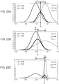
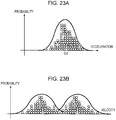
- a distribution of the acceleration components of the state estimation result values is compared with a distribution of the velocity components of the state estimation result values with reference to FIGS. 23A and 23B .
- calculated acceleration components and velocity components are represented by blank circles, and the distributions thereof are represented by curves.
- the acceleration components of the state estimation result values have a distribution of variations symmetrical with respect to 0.0, and tend to have a constant value for a long period of time.
- the velocity components of the state estimation result values have no such distribution of variations as the one symmetrical with respect to a particular value, and have no such a property as the one remaining constant for a long period of time. The use of the acceleration components of the state estimation result values for the evaluation of the reliability provides stable results.
- the variance var(t) of the acceleration component of the state estimation result value is updated with the past output value of the filter.
- the variance ⁇ f 2 (t) of the error distribution used in the filtering process of the state estimation result value u f (t) as a process target at time t is calculated in this way.
- the ratio of the variance ⁇ f 2 of the error distribution to the variance ⁇ r 2 of the likelihood distribution is a relative value, and a fixed value is used for the variance ⁇ r 2 .
- the predictive output value u r is calculated to determine the output value u p of the filter as discussed with reference to equations (7). A method of calculating the predictive output value u r is described below.
- the predictive output value u r of the filtering process with a state estimation result value u f as a process target is predicted from the filtering process results heretofore obtained.
- a motion model is assumed.
- the constant velocity motion model is adopted.
- the constant velocity motion model is based on the property that the variation of the face is typically continuous.
- a constant acceleration motion meaning a change in velocity of the face orientation
- the motion model for determining the state estimation result value u f may be any of these models.
- a current output value is predicted based on an immediately preceding output value and an immediately preceding acceleration value in the filtering process.
- the values thus determined are the variance ( ⁇ f 2 ) of the error distribution represented by the normal distribution curve f(x), the variance ( ⁇ r 2 ) of the likelihood represented by the normal distribution curve r(x), and the predictive output value u r predicted from the results of the filtering process obtained heretofore.
- the expected value of the normal distribution curve p(x) i.e., the output value u p of the filter, is calculated.
- FIG. 24 is a block diagram of a filtering processor 71.
- the filtering processor 71 illustrated in FIG. 24 includes a controller 72, an acceleration calculator 73, an acceleration variance updater 74, a Mahalanobis's distance calculator 75, a memory 76, a predictor 77, a holder 78, and a filtering calculator 79.
- the filtering processor 71 may be used in place of the filtering processor 42 of FIG. 1 .
- the controller 72 receives the parameter calculated by each parameter calculator in the parameter generator 17, i.e., the state estimation result value u f .
- the controller 72 controls each element in the filtering processor 71, for example, controls the supplying of the state estimation result value u f to the acceleration calculator 73 and the filtering calculator 79.
- the filtering process of the state estimation result value u f (t) at time t is described below.
- the acceleration calculator 73 When the acceleration calculator 73 receives the state estimation result value u f (t) from the controller 72, the acceleration calculator 73 also receives the output value u p (t-1) at time t-1 and the output value u p (t-2) at time t-2. By calculating equation (8), the acceleration calculator 73 calculates the acceleration component acc(t) of the state estimation result value u f (t), and then supplies the calculated acceleration component acc(t) to the acceleration variance updater 74 and the Mahalanobis's distance calculator 75.
- the acceleration variance updater 74 Upon receiving the acceleration component acc(t) of the state estimation result value u f (t) from the acceleration calculator 73, the acceleration variance updater 74 calculates equation (9). The acceleration variance updater 74 thus calculates the variance var(t) of the acceleration component of the state estimation result value and then supplies the calculated variance var(t) to the Mahalanobis's distance calculator 75.
- the Mahalanobis's distance calculator 75 calculates the variance ⁇ f 2 of the error distribution (in accordance with equations (10)) and then supplies the calculated variance ⁇ f 2 to the filtering calculator 79.
- the memory 76 stores the variance ⁇ r 2 of the likelihood distribution as the fixed value, and the filtering calculator 79 receives from the memory 76 the variance ⁇ r 2 of the likelihood distribution.
- the predictor 77 receives the output value u p from the filtering processor 71. On the basis of the output value u p (t-1) at time t-1 and the output value u p (t-2) at time t-2, the predictor 77 calculates equation (11), thereby calculating the predictive output value u r (t). The predictor 77 then supplies the predictive output value u r (t) to the filtering processor 71.
- the holder 78 receives the output value u p from the filtering processor 71.
- the holder 78 holds the output value u p , and supplies the output value u p (t-1) and the output value u p (t-2) to the acceleration calculator 73.
- the filtering calculator 79 calculates equations (7) based on the state estimation result value u f (t) supplied by the controller 72, the variance ⁇ f 2 (t) of the error distribution supplied by the Mahalanobis's distance calculator 75, the variance ⁇ r 2 (t) of the likelihood distribution read from the memory 76, and the predictive output value u r (t) supplied by the predictor 77.
- the filtering calculator 79 thus determines and outputs the output value u p (t).
- the filtering processor 71 can evaluate the reliability of the state estimation result value u f only after a certain number of acceleration components acc(sample) are stored. After a predetermined number of acceleration components acc are stored, the controller 72 performs the control process such that the filtering calculator 79 outputs calculation results.
- the filtering process of the filtering processor 71 is described below with reference to a flowchart of FIG. 25 .
- the filtering process of the filtering processor 71 is executed in step S22 of FIG. 14 .
- the filtering process starts when the parameter, i.e., the state estimation result value u f (t) is output from each parameter calculator in the parameter generator 17 to the filtering processor 71.
- step S71 the controller 72 determines whether the supplied state estimation result value u f (t) is a new process target of the filtering process.
- step S71 If the controller 72 determines in step S71 that the supplied state estimation result value u f (t) is a new process target of the filtering process, processing proceeds to step S72.
- the controller 72 initializes each element in the filtering processor 71. For example, the controller 72 sets zeroes as initial values to internal variables (the variance var, the predictive output value u r , and the output value u p ) used by the acceleration variance updater 74, the predictor 77, and the filtering calculator 79.
- internal variables the variance var, the predictive output value u r , and the output value u p
- step S73 If the controller 72 determines in step S71 that the supplied state estimation result value u f (t) is not a new process target of the filtering process, processing proceeds to step S73.
- the controller 72 supplies the state estimation result value u f (t) to the acceleration calculator 73.
- the acceleration calculator 73 also receives from the holder 78 the output value u p (t-1) at time t-1 and the output value u p (t-2) at time t-2.
- the acceleration calculator 73 calculates equation (8) based on the state estimation result value u f (t), the output value u p (t-1), and the output value u p (t-2).
- the acceleration calculator 73 thus determines the acceleration component acc(t) of the state estimation result value u f (t) and supplies the acceleration component acc(t) to the acceleration variance updater 74.
- step S74 The acceleration variance updater 74 calculates equation (9) based on the acceleration component acc(t) supplied by the acceleration calculator 73 in step S73.
- the acceleration variance updater 74 thus determines the variance var(t) of the acceleration component of the state estimation result value. Processing proceeds to step S75.
- step S75 the controller 72 determines whether a sufficient number of acceleration components acc(t) are stored. In other words, the controller 72 determines whether the variance var(t) calculated in step S74 is determined from the number of state estimation result values u f large enough to evaluate the reliability of the state estimation result value u f . More specifically, the variance var(t) determined from a certain number of acceleration components acc(t) is used to evaluate the reliability of the state estimation result value u f . The controller 72 sets the certain number as a threshold value (for example, 20).
- a threshold value for example, 20
- the controller 72 determines that a sufficient number of acceleration components acc(t) are stored. On the other hand, if the number of acceleration components acc(t) the acceleration variance updater 74 has used to calculate the variance var(t) is smaller than the threshold value, the controller 72 determines that a sufficient number of acceleration components acc(t) are not stored.
- Step S73-S75 Since the output value u p (t-2) supplied by the holder 78 at time t-2 in step S73 is used, the process in steps S73-S75 is performed on an image two frames later than when it was determined that the supplied state estimation result value u f (t) was a new process target (when the output value u p (t-2) was output). Step S76 is performed with steps S73 and S75 skipped until two frames have been output since it was determined in step S71 that the state estimation result value u f (t) was the new target.
- step S76 the controller 72 outputs the supplied state estimation result value u f (t) as the output value u p (t) to the predictor 77 and the holder 78. Since the reliability of the state estimation result value u f (t) is not accurately evaluated, the filtering processor 71 does not calculate the output value u p . Subsequent to step S76, the filtering process thus ends. A next frame is then processed.
- step S77 the controller 72 controls the acceleration calculator 73 and the acceleration variance updater 74 such that the acceleration component acc(t) calculated in step S73 and the variance var(t) calculated in step S74 are output to the Mahalanobis's distance calculator 75.
- the Mahalanobis's distance calculator 75 calculates the variance ⁇ f 2 of the error distribution from the acceleration component acc(t) and the variance var(t), and supplies the variance ⁇ f 2 of the error distribution to the filtering calculator 79. Processing proceeds to step S78.
- step S78 the predictor 77 calculates equation (11) based on the output value u p (t-1) at time t-1 and the output value u p (t-2) at time t-2, thereby determining the predictive output value u r .
- the predictor 77 then supplies the predictive output value u r to the filtering processor 71.
- step S78 The controller 72 supplies the state estimation result value u f (t) to the filtering calculator 79.
- the filtering calculator 79 reads the variance ⁇ r 2 of the likelihood distribution from the memory 76.
- the filtering calculator 79 calculates equations (7), based on the state estimation result value u f (t), the variance ⁇ r 2 of the likelihood distribution, the variance ⁇ f 2 of the error distribution supplied in step S77, and the predictive output value u r supplied in step S78.
- the filtering calculator 79 thus determines and outputs the output value u p (t). The filtering process thus ends.
- the filtering processor 71 reduces the variation. Since such a fluctuating parameter has a low reliability (the variance ⁇ f 2 ), the filtering processor 71 outputs a predictive output value. Variations caused by the calculation error are thus reduced. A stable and robust filtering process is thus performed. Such an arrangement is also free from a delay that could take place if a filtering processor constructed of a multi-stage filter was used.
- the image generator 18 generates the avatar using the parameter filtering processed by the filtering processor 71.
- the image generator 18 thus generates the avatar having a high follow-up property responsive to a change in the state of the face of the user, and moving naturally and smoothly in a manner free from vibrations caused by a calculation error of the parameters (irregular variations of the parameters).
- the above-described filtering process is performed on a single parameter.
- the parameters are integrally used by using a state vector and a covariance matrix on a plurality of parameters calculated by the parameter calculators in the parameter generator 17.
- the use of the state vector results in an interactive effect between states (parameters), and a more robust filtering process is thus performed.
- the series of process steps described above may be performed using hardware or software. If the process steps are performed using software, a program forming the software is installed on a computer from a program recording medium.
- the computers include a computer in a dedicated hardware system, and a general-purpose personal computer that performs a variety of functions with a variety of programs installed thereon.
- Fig. 26 is a block diagram illustrating a hardware structure of a computer that performs the above-described process steps.
- a CPU 101 In the computer, a CPU 101, a read-only memory (ROM) 102, and a random-access memory (RAM) 103 are interconnected to each other via a bus 104.
- ROM read-only memory
- RAM random-access memory
- the bus 104 is connected to an input-output interface 105. Also connected to the input-output interface 105 are an input unit 106, an output unit 107, a storage unit 108, a communication unit 109, and a drive 110.
- the input unit 106 includes a keyboard, a mouse, a microphone, etc.
- the output unit 107 includes a display, a loudspeaker, etc.
- the storage unit 108 includes a hard disk, a non-volatile memory, etc.
- the communication unit 109 includes a network interface, etc.
- the drive 110 drives a removable medium 111, such as a magnetic disc, an optical disc, or a semiconductor memory.
- the CPU 101 in the computer thus constructed performs the above-described series of process steps by loading a program from the storage unit 108 onto the RAM 104 via the input-output interface 105 and the bus 104, and then executing the program.
- the program to be executed by the CPU 101 is supplied on the removable medium 111 as a package medium, such as a magnetic disk (flexible disk), an optical disk (compact-disc read-only memory (CD-ROM), a digital versatile disc (DVD)), magneto-optical disc, or a semiconductor memory.
- the program may also be supplied using wired or wireless transmission media, such as a local-area network (LAN), the Internet, or a digital broadcasting satellite.
- LAN local-area network
- the Internet or a digital broadcasting satellite.
- the program may be installed onto the storage unit 108 in the computer through the input-output interface 105 by loading the removable medium 111 onto the drive 110.
- the program may be received by the communication unit 109 via wired or wireless transmission media, and then installed onto the storage unit 108.
- the program may also be pre-installed onto the ROM 102 or the storage unit 108.
- the program may be executed by the computer with the process steps in the time-series order previously described or with several process steps in parallel or at an appropriate timing at which a call is made.
- the program may be executed by a single CPU or a plurality of CPUs.
Landscapes
- Engineering & Computer Science (AREA)
- Theoretical Computer Science (AREA)
- Physics & Mathematics (AREA)
- General Physics & Mathematics (AREA)
- Oral & Maxillofacial Surgery (AREA)
- Health & Medical Sciences (AREA)
- General Health & Medical Sciences (AREA)
- Human Computer Interaction (AREA)
- Multimedia (AREA)
- Computer Vision & Pattern Recognition (AREA)
- Processing Or Creating Images (AREA)
- Image Processing (AREA)
- Image Analysis (AREA)
Applications Claiming Priority (2)
| Application Number | Priority Date | Filing Date | Title |
|---|---|---|---|
| JP2009201028 | 2009-08-31 | ||
| JP2009284807A JP5423379B2 (ja) | 2009-08-31 | 2009-12-16 | 画像処理装置および画像処理方法、並びにプログラム |
Publications (3)
| Publication Number | Publication Date |
|---|---|
| EP2293221A2 EP2293221A2 (en) | 2011-03-09 |
| EP2293221A3 EP2293221A3 (en) | 2014-04-23 |
| EP2293221B1 true EP2293221B1 (en) | 2018-11-28 |
Family
ID=43304648
Family Applications (1)
| Application Number | Title | Priority Date | Filing Date |
|---|---|---|---|
| EP10173731.0A Not-in-force EP2293221B1 (en) | 2009-08-31 | 2010-08-23 | Apparatus, method, and program for processing image |
Country Status (4)
| Country | Link |
|---|---|
| US (1) | US8634658B2 (enExample) |
| EP (1) | EP2293221B1 (enExample) |
| JP (1) | JP5423379B2 (enExample) |
| CN (1) | CN102004897B (enExample) |
Families Citing this family (72)
| Publication number | Priority date | Publication date | Assignee | Title |
|---|---|---|---|---|
| US8359642B1 (en) * | 2010-06-25 | 2013-01-22 | Sprint Communications Company L.P. | Restricting mature content |
| US20110316697A1 (en) * | 2010-06-29 | 2011-12-29 | General Electric Company | System and method for monitoring an entity within an area |
| KR20120011920A (ko) * | 2010-07-27 | 2012-02-09 | 삼성전자주식회사 | 디지털 영상 신호 처리 장치, 디지털 영상 신호 처리 방법 및 상기 방법을 기록한 기록 매체 |
| JP2012244526A (ja) * | 2011-05-23 | 2012-12-10 | Sony Corp | 情報処理装置、情報処理方法及びコンピュータプログラム |
| US9088426B2 (en) | 2011-12-13 | 2015-07-21 | Google Inc. | Processing media streams during a multi-user video conference |
| WO2013097139A1 (en) * | 2011-12-29 | 2013-07-04 | Intel Corporation | Communication using avatar |
| US9888171B2 (en) * | 2012-02-13 | 2018-02-06 | Htc Corporation | Mobile camera device capable of improving facial patterns of a captured image |
| WO2013138531A1 (en) | 2012-03-14 | 2013-09-19 | Google, Inc. | Modifying an appearance of a participant during a video conference |
| JP5880182B2 (ja) * | 2012-03-19 | 2016-03-08 | カシオ計算機株式会社 | 画像生成装置、画像生成方法及びプログラム |
| US9595298B2 (en) | 2012-07-18 | 2017-03-14 | Microsoft Technology Licensing, Llc | Transforming data to create layouts |
| JP2014068107A (ja) * | 2012-09-25 | 2014-04-17 | Zenrin Datacom Co Ltd | 画像処理装置、画像処理システム、画像処理方法およびコンピュータプログラム |
| JP6102939B2 (ja) * | 2012-11-22 | 2017-03-29 | ソニー株式会社 | 情報処理装置、システム、情報処理方法およびプログラム |
| CN103903292B (zh) * | 2012-12-27 | 2017-04-19 | 北京新媒传信科技有限公司 | 一种实现头像编辑界面的方法和系统 |
| JP6268722B2 (ja) * | 2013-03-06 | 2018-01-31 | 日本電気株式会社 | 表示装置、表示方法、及び、プログラム |
| WO2014187919A1 (en) * | 2013-05-23 | 2014-11-27 | bioMérieux | Method, system and computer program product for producing a raised relief map from images of an object |
| US9202119B2 (en) * | 2013-10-18 | 2015-12-01 | Daon Holdings Limited | Methods and systems for determining user liveness |
| US20150317511A1 (en) * | 2013-11-07 | 2015-11-05 | Orbeus, Inc. | System, method and apparatus for performing facial recognition |
| CN104657974A (zh) * | 2013-11-25 | 2015-05-27 | 腾讯科技(上海)有限公司 | 一种图像处理方法及装置 |
| US9614724B2 (en) | 2014-04-21 | 2017-04-04 | Microsoft Technology Licensing, Llc | Session-based device configuration |
| US9639742B2 (en) | 2014-04-28 | 2017-05-02 | Microsoft Technology Licensing, Llc | Creation of representative content based on facial analysis |
| US9773156B2 (en) * | 2014-04-29 | 2017-09-26 | Microsoft Technology Licensing, Llc | Grouping and ranking images based on facial recognition data |
| US10111099B2 (en) | 2014-05-12 | 2018-10-23 | Microsoft Technology Licensing, Llc | Distributing content in managed wireless distribution networks |
| US9874914B2 (en) | 2014-05-19 | 2018-01-23 | Microsoft Technology Licensing, Llc | Power management contracts for accessory devices |
| US10037202B2 (en) | 2014-06-03 | 2018-07-31 | Microsoft Technology Licensing, Llc | Techniques to isolating a portion of an online computing service |
| US9460493B2 (en) | 2014-06-14 | 2016-10-04 | Microsoft Technology Licensing, Llc | Automatic video quality enhancement with temporal smoothing and user override |
| US9717006B2 (en) | 2014-06-23 | 2017-07-25 | Microsoft Technology Licensing, Llc | Device quarantine in a wireless network |
| US9373179B2 (en) | 2014-06-23 | 2016-06-21 | Microsoft Technology Licensing, Llc | Saliency-preserving distinctive low-footprint photograph aging effect |
| JP6476608B2 (ja) * | 2014-06-30 | 2019-03-06 | カシオ計算機株式会社 | 動作処理装置、動作処理方法及びプログラム |
| US9444999B2 (en) * | 2014-08-05 | 2016-09-13 | Omnivision Technologies, Inc. | Feature detection in image capture |
| US10282069B2 (en) | 2014-09-30 | 2019-05-07 | Microsoft Technology Licensing, Llc | Dynamic presentation of suggested content |
| US9626768B2 (en) * | 2014-09-30 | 2017-04-18 | Microsoft Technology Licensing, Llc | Optimizing a visual perspective of media |
| US20180025175A1 (en) | 2015-01-15 | 2018-01-25 | Nec Corporation | Information output device, camera, information output system, information output method, and program |
| DE102015223175A1 (de) * | 2015-11-24 | 2017-05-24 | Conti Temic Microelectronic Gmbh | Fahrerassistenzsystem mit adaptiver Umgebungsbilddatenverarbeitung |
| WO2017137952A1 (en) * | 2016-02-10 | 2017-08-17 | Vats Nitin | Intelligent chatting on digital communication network |
| JP6794144B2 (ja) * | 2016-06-03 | 2020-12-02 | 東芝テック株式会社 | 操作入力装置、販売データ処理装置及びプログラム |
| US10452896B1 (en) * | 2016-09-06 | 2019-10-22 | Apple Inc. | Technique for creating avatar from image data |
| DK179978B1 (en) | 2016-09-23 | 2019-11-27 | Apple Inc. | IMAGE DATA FOR ENHANCED USER INTERACTIONS |
| JP2018055619A (ja) * | 2016-09-30 | 2018-04-05 | 株式会社ブイシンク | 画像表示装置 |
| JP6266736B1 (ja) * | 2016-12-07 | 2018-01-24 | 株式会社コロプラ | 仮想空間を介して通信するための方法、当該方法をコンピュータに実行させるためのプログラム、および当該プログラムを実行するための情報処理装置 |
| CN108268227B (zh) * | 2017-01-04 | 2020-12-01 | 京东方科技集团股份有限公司 | 显示设备 |
| US11010947B2 (en) | 2017-01-23 | 2021-05-18 | Ntt Docomo, Inc. | Information processing system and information processing apparatus |
| US10380228B2 (en) | 2017-02-10 | 2019-08-13 | Microsoft Technology Licensing, Llc | Output generation based on semantic expressions |
| KR102798516B1 (ko) | 2017-05-16 | 2025-04-23 | 애플 인크. | 이모지 레코딩 및 전송 |
| KR101966384B1 (ko) * | 2017-06-29 | 2019-08-13 | 라인 가부시키가이샤 | 영상 처리 방법 및 시스템 |
| US10870056B2 (en) * | 2017-11-01 | 2020-12-22 | Sony Interactive Entertainment Inc. | Emoji-based communications derived from facial features during game play |
| US11068141B1 (en) * | 2018-02-02 | 2021-07-20 | Snap Inc. | Device-based image modification of depicted objects |
| JP7279646B2 (ja) * | 2018-02-07 | 2023-05-23 | ソニーグループ株式会社 | 情報処理装置、情報処理方法及びプログラム |
| KR102661019B1 (ko) | 2018-02-23 | 2024-04-26 | 삼성전자주식회사 | 얼굴에 대응하는 3차원 아바타를 이용하여 얼굴의 움직임이 반영된 3차원 아바타를 포함하는 이미지를 생성하는 전자 장치 및 그 동작 방법 |
| JP2019164614A (ja) * | 2018-03-20 | 2019-09-26 | 株式会社ViRD | アバター制御プログラム |
| JP6941800B2 (ja) | 2018-04-04 | 2021-09-29 | パナソニックIpマネジメント株式会社 | 感情推定装置、感情推定方法及びプログラム |
| DK201870374A1 (en) | 2018-05-07 | 2019-12-04 | Apple Inc. | AVATAR CREATION USER INTERFACE |
| US12033296B2 (en) | 2018-05-07 | 2024-07-09 | Apple Inc. | Avatar creation user interface |
| KR102530264B1 (ko) * | 2018-08-08 | 2023-05-09 | 삼성전자 주식회사 | 아바타에 대응하는 속성에 따른 아이템을 제공하는 방법 및 장치 |
| CN109447894A (zh) * | 2018-08-20 | 2019-03-08 | 广州市久邦数码科技有限公司 | 一种基于数据分析的图像处理方法及其系统 |
| CN111079479A (zh) | 2018-10-19 | 2020-04-28 | 北京市商汤科技开发有限公司 | 小孩状态分析方法和装置、车辆、电子设备、存储介质 |
| US11107261B2 (en) | 2019-01-18 | 2021-08-31 | Apple Inc. | Virtual avatar animation based on facial feature movement |
| CN111488759A (zh) * | 2019-01-25 | 2020-08-04 | 北京字节跳动网络技术有限公司 | 动物脸部的图像处理方法和装置 |
| KR102664688B1 (ko) | 2019-02-19 | 2024-05-10 | 삼성전자 주식회사 | 가상 캐릭터 기반 촬영 모드를 제공하는 전자 장치 및 이의 동작 방법 |
| JP7295388B2 (ja) * | 2019-03-08 | 2023-06-21 | フリュー株式会社 | 画像処理装置、画像処理方法及び画像処理プログラム |
| EP3942544A1 (en) * | 2019-03-22 | 2022-01-26 | Essilor International | Device for simulating a physiological behaviour of a mammal using a virtual mammal, process and computer program |
| DK201970531A1 (en) | 2019-05-06 | 2021-07-09 | Apple Inc | Avatar integration with multiple applications |
| CN110674765A (zh) * | 2019-09-27 | 2020-01-10 | 上海依图网络科技有限公司 | 摄像系统以及视频处理方法 |
| JP7319172B2 (ja) * | 2019-11-13 | 2023-08-01 | 富士フイルム株式会社 | 画像処理装置、画像処理方法及び画像処理システム |
| CN111698552A (zh) * | 2020-05-15 | 2020-09-22 | 完美世界(北京)软件科技发展有限公司 | 一种视频资源的生成方法和装置 |
| KR20250130851A (ko) | 2020-06-08 | 2025-09-02 | 애플 인크. | 3차원 환경들에서 아바타들의 제시 |
| CN111833418B (zh) * | 2020-07-14 | 2024-03-29 | 北京百度网讯科技有限公司 | 动画交互方法、装置、设备以及存储介质 |
| CN112001932B (zh) * | 2020-09-01 | 2023-10-31 | 腾讯科技(深圳)有限公司 | 人脸识别方法、装置、计算机设备和存储介质 |
| US11438551B2 (en) * | 2020-09-15 | 2022-09-06 | At&T Intellectual Property I, L.P. | Virtual audience using low bitrate avatars and laughter detection |
| JP7217838B2 (ja) * | 2020-09-24 | 2023-02-03 | 三菱電機株式会社 | 開口度算出装置 |
| JP7613906B2 (ja) * | 2020-12-18 | 2025-01-15 | トヨタ自動車株式会社 | 画像処理システム |
| US12310663B2 (en) * | 2021-06-10 | 2025-05-27 | EyesMatch Ltd. | System and method for digital optician measurements |
| KR102826023B1 (ko) * | 2022-11-30 | 2025-06-27 | 주식회사 케이티 | 음성 데이터에 기초하여 얼굴 이미지를 생성하는 장치, 방법 및 컴퓨터 프로그램 |
Family Cites Families (26)
| Publication number | Priority date | Publication date | Assignee | Title |
|---|---|---|---|---|
| US6332123B1 (en) * | 1989-03-08 | 2001-12-18 | Kokusai Denshin Denwa Kabushiki Kaisha | Mouth shape synthesizing |
| JPH0744727A (ja) | 1993-07-27 | 1995-02-14 | Sony Corp | 画像作成方法およびその装置 |
| JP2000306095A (ja) * | 1999-04-16 | 2000-11-02 | Fujitsu Ltd | 画像照合・検索システム |
| IT1320002B1 (it) * | 2000-03-31 | 2003-11-12 | Cselt Centro Studi Lab Telecom | Procedimento per l'animazione di un modello sintetizzato di voltoumano pilotata da un segnale audio. |
| JP2002108382A (ja) * | 2000-09-27 | 2002-04-10 | Sony Corp | リップシンクを行うアニメーション方法および装置 |
| JP2002232783A (ja) | 2001-02-06 | 2002-08-16 | Sony Corp | 画像処理装置および画像処理方法、並びにプログラム記憶媒体 |
| US20030007700A1 (en) * | 2001-07-03 | 2003-01-09 | Koninklijke Philips Electronics N.V. | Method and apparatus for interleaving a user image in an original image sequence |
| GB2382289B (en) * | 2001-09-28 | 2005-07-06 | Canon Kk | Method and apparatus for generating models of individuals |
| JP3822828B2 (ja) * | 2002-03-20 | 2006-09-20 | 沖電気工業株式会社 | 3次元画像生成装置およびその画像生成方法ならびにその画像生成プログラムを記録したコンピュータ読取り可能な記録媒体 |
| JP2003308533A (ja) * | 2002-04-17 | 2003-10-31 | Mitsubishi Electric Corp | ドライバの顔画像処理装置 |
| US7133535B2 (en) * | 2002-12-21 | 2006-11-07 | Microsoft Corp. | System and method for real time lip synchronization |
| US7711155B1 (en) * | 2003-04-14 | 2010-05-04 | Videomining Corporation | Method and system for enhancing three dimensional face modeling using demographic classification |
| EP1653279B1 (en) * | 2003-07-15 | 2019-02-06 | Omron Corporation | Object decision device and imaging device |
| JP4517633B2 (ja) | 2003-11-25 | 2010-08-04 | ソニー株式会社 | 対象物検出装置及び方法 |
| JP4482796B2 (ja) | 2004-03-26 | 2010-06-16 | ソニー株式会社 | 情報処理装置および方法、記録媒体、並びにプログラム |
| JP2006064973A (ja) * | 2004-08-26 | 2006-03-09 | Crimson Technology Inc | 制御システム |
| US7634106B2 (en) * | 2004-09-22 | 2009-12-15 | Fujifilm Corporation | Synthesized image generation method, synthesized image generation apparatus, and synthesized image generation program |
| DE602006009191D1 (de) * | 2005-07-26 | 2009-10-29 | Canon Kk | Bildaufnahmegerät und -verfahren |
| US20070080967A1 (en) * | 2005-10-11 | 2007-04-12 | Animetrics Inc. | Generation of normalized 2D imagery and ID systems via 2D to 3D lifting of multifeatured objects |
| US7728866B2 (en) * | 2005-11-03 | 2010-06-01 | Broadcom Corp. | Video telephony image processing |
| JP2007156650A (ja) | 2005-12-01 | 2007-06-21 | Sony Corp | 画像処理装置 |
| JP2007213182A (ja) * | 2006-02-08 | 2007-08-23 | Fujifilm Corp | 対象物状態認識方法および装置並びにプログラム |
| JP4093273B2 (ja) * | 2006-03-13 | 2008-06-04 | オムロン株式会社 | 特徴点検出装置、特徴点検出方法および特徴点検出プログラム |
| JP2008021266A (ja) * | 2006-07-14 | 2008-01-31 | Matsushita Electric Ind Co Ltd | 顔向き検出装置、顔向き検出方法、および顔向き検出プログラム |
| JP4424364B2 (ja) * | 2007-03-19 | 2010-03-03 | ソニー株式会社 | 画像処理装置、画像処理方法 |
| JP4569670B2 (ja) * | 2008-06-11 | 2010-10-27 | ソニー株式会社 | 画像処理装置、画像処理方法およびプログラム |
-
2009
- 2009-12-16 JP JP2009284807A patent/JP5423379B2/ja not_active Expired - Fee Related
-
2010
- 2010-07-02 US US12/829,870 patent/US8634658B2/en active Active
- 2010-07-29 CN CN2010102420292A patent/CN102004897B/zh not_active Expired - Fee Related
- 2010-08-23 EP EP10173731.0A patent/EP2293221B1/en not_active Not-in-force
Non-Patent Citations (1)
| Title |
|---|
| None * |
Also Published As
| Publication number | Publication date |
|---|---|
| US8634658B2 (en) | 2014-01-21 |
| JP2011070623A (ja) | 2011-04-07 |
| EP2293221A3 (en) | 2014-04-23 |
| EP2293221A2 (en) | 2011-03-09 |
| JP5423379B2 (ja) | 2014-02-19 |
| CN102004897A (zh) | 2011-04-06 |
| CN102004897B (zh) | 2013-11-27 |
| US20110052081A1 (en) | 2011-03-03 |
Similar Documents
| Publication | Publication Date | Title |
|---|---|---|
| EP2293221B1 (en) | Apparatus, method, and program for processing image | |
| Thambiraja et al. | Imitator: Personalized speech-driven 3d facial animation | |
| US20240087200A1 (en) | Systems and methods for real-time complex character animations and interactivity | |
| CN112967212B (zh) | 一种虚拟人物的合成方法、装置、设备及存储介质 | |
| US11600013B2 (en) | Facial features tracker with advanced training for natural rendering of human faces in real-time | |
| US10169905B2 (en) | Systems and methods for animating models from audio data | |
| US10559111B2 (en) | Systems and methods for generating computer ready animation models of a human head from captured data images | |
| US8692830B2 (en) | Automatic avatar creation | |
| EP4283577B1 (en) | Text and audio-based real-time face reenactment | |
| CN110910479B (zh) | 视频处理方法、装置、电子设备及可读存储介质 | |
| CN113255457A (zh) | 基于人脸表情识别的动画角色面部表情生成方法及系统 | |
| Mattos et al. | Improving CNN-based viseme recognition using synthetic data | |
| Mattos et al. | Multi-view mouth renderization for assisting lip-reading | |
| CN119379867B (zh) | 虚拟对象驱动及模型训练方法、装置、设备和介质 | |
| WO2025232361A1 (zh) | 一种视频生成方法和相关装置 | |
| Hwang et al. | Audio-driven facial animation: A survey | |
| Müller et al. | Realistic speech animation based on observed 3-D face dynamics | |
| USRE49044E1 (en) | Automatic avatar creation | |
| WO2024158985A1 (en) | Robust facial animation from video and audio | |
| Liu et al. | Optimization of an image-based talking head system | |
| US20250329092A1 (en) | Method, device, and program product for generating avatar animation | |
| US20250363702A1 (en) | Composite avatar | |
| US20250173937A1 (en) | Artificial intelligence device for image augmented speech-driven 3d facial animaion and method thereof | |
| US20250378643A1 (en) | Mesh generation using prompts | |
| Sundararaman et al. | Seeing Voices: Generating A-Roll Video from Audio with Mirage |
Legal Events
| Date | Code | Title | Description |
|---|---|---|---|
| PUAI | Public reference made under article 153(3) epc to a published international application that has entered the european phase |
Free format text: ORIGINAL CODE: 0009012 |
|
| 17P | Request for examination filed |
Effective date: 20100823 |
|
| AK | Designated contracting states |
Kind code of ref document: A2 Designated state(s): AL AT BE BG CH CY CZ DE DK EE ES FI FR GB GR HR HU IE IS IT LI LT LU LV MC MK MT NL NO PL PT RO SE SI SK SM TR |
|
| AX | Request for extension of the european patent |
Extension state: BA ME RS |
|
| PUAL | Search report despatched |
Free format text: ORIGINAL CODE: 0009013 |
|
| AK | Designated contracting states |
Kind code of ref document: A3 Designated state(s): AL AT BE BG CH CY CZ DE DK EE ES FI FR GB GR HR HU IE IS IT LI LT LU LV MC MK MT NL NO PL PT RO SE SI SK SM TR |
|
| AX | Request for extension of the european patent |
Extension state: BA ME RS |
|
| RIC1 | Information provided on ipc code assigned before grant |
Ipc: G06K 9/00 20060101AFI20140319BHEP Ipc: G06T 11/60 20060101ALI20140319BHEP |
|
| STAA | Information on the status of an ep patent application or granted ep patent |
Free format text: STATUS: EXAMINATION IS IN PROGRESS |
|
| 17Q | First examination report despatched |
Effective date: 20180131 |
|
| GRAP | Despatch of communication of intention to grant a patent |
Free format text: ORIGINAL CODE: EPIDOSNIGR1 |
|
| STAA | Information on the status of an ep patent application or granted ep patent |
Free format text: STATUS: GRANT OF PATENT IS INTENDED |
|
| INTG | Intention to grant announced |
Effective date: 20180619 |
|
| GRAS | Grant fee paid |
Free format text: ORIGINAL CODE: EPIDOSNIGR3 |
|
| GRAA | (expected) grant |
Free format text: ORIGINAL CODE: 0009210 |
|
| STAA | Information on the status of an ep patent application or granted ep patent |
Free format text: STATUS: THE PATENT HAS BEEN GRANTED |
|
| AK | Designated contracting states |
Kind code of ref document: B1 Designated state(s): AL AT BE BG CH CY CZ DE DK EE ES FI FR GB GR HR HU IE IS IT LI LT LU LV MC MK MT NL NO PL PT RO SE SI SK SM TR |
|
| REG | Reference to a national code |
Ref country code: GB Ref legal event code: FG4D |
|
| REG | Reference to a national code |
Ref country code: CH Ref legal event code: EP |
|
| REG | Reference to a national code |
Ref country code: AT Ref legal event code: REF Ref document number: 1071080 Country of ref document: AT Kind code of ref document: T Effective date: 20181215 |
|
| REG | Reference to a national code |
Ref country code: DE Ref legal event code: R096 Ref document number: 602010055402 Country of ref document: DE |
|
| REG | Reference to a national code |
Ref country code: IE Ref legal event code: FG4D |
|
| REG | Reference to a national code |
Ref country code: NL Ref legal event code: MP Effective date: 20181128 |
|
| REG | Reference to a national code |
Ref country code: LT Ref legal event code: MG4D |
|
| REG | Reference to a national code |
Ref country code: AT Ref legal event code: MK05 Ref document number: 1071080 Country of ref document: AT Kind code of ref document: T Effective date: 20181128 |
|
| PG25 | Lapsed in a contracting state [announced via postgrant information from national office to epo] |
Ref country code: LT Free format text: LAPSE BECAUSE OF FAILURE TO SUBMIT A TRANSLATION OF THE DESCRIPTION OR TO PAY THE FEE WITHIN THE PRESCRIBED TIME-LIMIT Effective date: 20181128 Ref country code: NO Free format text: LAPSE BECAUSE OF FAILURE TO SUBMIT A TRANSLATION OF THE DESCRIPTION OR TO PAY THE FEE WITHIN THE PRESCRIBED TIME-LIMIT Effective date: 20190228 Ref country code: BG Free format text: LAPSE BECAUSE OF FAILURE TO SUBMIT A TRANSLATION OF THE DESCRIPTION OR TO PAY THE FEE WITHIN THE PRESCRIBED TIME-LIMIT Effective date: 20190228 Ref country code: HR Free format text: LAPSE BECAUSE OF FAILURE TO SUBMIT A TRANSLATION OF THE DESCRIPTION OR TO PAY THE FEE WITHIN THE PRESCRIBED TIME-LIMIT Effective date: 20181128 Ref country code: AT Free format text: LAPSE BECAUSE OF FAILURE TO SUBMIT A TRANSLATION OF THE DESCRIPTION OR TO PAY THE FEE WITHIN THE PRESCRIBED TIME-LIMIT Effective date: 20181128 Ref country code: IS Free format text: LAPSE BECAUSE OF FAILURE TO SUBMIT A TRANSLATION OF THE DESCRIPTION OR TO PAY THE FEE WITHIN THE PRESCRIBED TIME-LIMIT Effective date: 20190328 Ref country code: ES Free format text: LAPSE BECAUSE OF FAILURE TO SUBMIT A TRANSLATION OF THE DESCRIPTION OR TO PAY THE FEE WITHIN THE PRESCRIBED TIME-LIMIT Effective date: 20181128 Ref country code: LV Free format text: LAPSE BECAUSE OF FAILURE TO SUBMIT A TRANSLATION OF THE DESCRIPTION OR TO PAY THE FEE WITHIN THE PRESCRIBED TIME-LIMIT Effective date: 20181128 Ref country code: FI Free format text: LAPSE BECAUSE OF FAILURE TO SUBMIT A TRANSLATION OF THE DESCRIPTION OR TO PAY THE FEE WITHIN THE PRESCRIBED TIME-LIMIT Effective date: 20181128 |
|
| PG25 | Lapsed in a contracting state [announced via postgrant information from national office to epo] |
Ref country code: GR Free format text: LAPSE BECAUSE OF FAILURE TO SUBMIT A TRANSLATION OF THE DESCRIPTION OR TO PAY THE FEE WITHIN THE PRESCRIBED TIME-LIMIT Effective date: 20190301 Ref country code: AL Free format text: LAPSE BECAUSE OF FAILURE TO SUBMIT A TRANSLATION OF THE DESCRIPTION OR TO PAY THE FEE WITHIN THE PRESCRIBED TIME-LIMIT Effective date: 20181128 Ref country code: SE Free format text: LAPSE BECAUSE OF FAILURE TO SUBMIT A TRANSLATION OF THE DESCRIPTION OR TO PAY THE FEE WITHIN THE PRESCRIBED TIME-LIMIT Effective date: 20181128 Ref country code: PT Free format text: LAPSE BECAUSE OF FAILURE TO SUBMIT A TRANSLATION OF THE DESCRIPTION OR TO PAY THE FEE WITHIN THE PRESCRIBED TIME-LIMIT Effective date: 20190328 |
|
| PG25 | Lapsed in a contracting state [announced via postgrant information from national office to epo] |
Ref country code: NL Free format text: LAPSE BECAUSE OF FAILURE TO SUBMIT A TRANSLATION OF THE DESCRIPTION OR TO PAY THE FEE WITHIN THE PRESCRIBED TIME-LIMIT Effective date: 20181128 |
|
| PG25 | Lapsed in a contracting state [announced via postgrant information from national office to epo] |
Ref country code: PL Free format text: LAPSE BECAUSE OF FAILURE TO SUBMIT A TRANSLATION OF THE DESCRIPTION OR TO PAY THE FEE WITHIN THE PRESCRIBED TIME-LIMIT Effective date: 20181128 Ref country code: IT Free format text: LAPSE BECAUSE OF FAILURE TO SUBMIT A TRANSLATION OF THE DESCRIPTION OR TO PAY THE FEE WITHIN THE PRESCRIBED TIME-LIMIT Effective date: 20181128 Ref country code: DK Free format text: LAPSE BECAUSE OF FAILURE TO SUBMIT A TRANSLATION OF THE DESCRIPTION OR TO PAY THE FEE WITHIN THE PRESCRIBED TIME-LIMIT Effective date: 20181128 Ref country code: CZ Free format text: LAPSE BECAUSE OF FAILURE TO SUBMIT A TRANSLATION OF THE DESCRIPTION OR TO PAY THE FEE WITHIN THE PRESCRIBED TIME-LIMIT Effective date: 20181128 |
|
| REG | Reference to a national code |
Ref country code: DE Ref legal event code: R097 Ref document number: 602010055402 Country of ref document: DE |
|
| PG25 | Lapsed in a contracting state [announced via postgrant information from national office to epo] |
Ref country code: RO Free format text: LAPSE BECAUSE OF FAILURE TO SUBMIT A TRANSLATION OF THE DESCRIPTION OR TO PAY THE FEE WITHIN THE PRESCRIBED TIME-LIMIT Effective date: 20181128 Ref country code: SM Free format text: LAPSE BECAUSE OF FAILURE TO SUBMIT A TRANSLATION OF THE DESCRIPTION OR TO PAY THE FEE WITHIN THE PRESCRIBED TIME-LIMIT Effective date: 20181128 Ref country code: EE Free format text: LAPSE BECAUSE OF FAILURE TO SUBMIT A TRANSLATION OF THE DESCRIPTION OR TO PAY THE FEE WITHIN THE PRESCRIBED TIME-LIMIT Effective date: 20181128 Ref country code: SK Free format text: LAPSE BECAUSE OF FAILURE TO SUBMIT A TRANSLATION OF THE DESCRIPTION OR TO PAY THE FEE WITHIN THE PRESCRIBED TIME-LIMIT Effective date: 20181128 |
|
| PLBE | No opposition filed within time limit |
Free format text: ORIGINAL CODE: 0009261 |
|
| STAA | Information on the status of an ep patent application or granted ep patent |
Free format text: STATUS: NO OPPOSITION FILED WITHIN TIME LIMIT |
|
| PG25 | Lapsed in a contracting state [announced via postgrant information from national office to epo] |
Ref country code: SI Free format text: LAPSE BECAUSE OF FAILURE TO SUBMIT A TRANSLATION OF THE DESCRIPTION OR TO PAY THE FEE WITHIN THE PRESCRIBED TIME-LIMIT Effective date: 20181128 |
|
| 26N | No opposition filed |
Effective date: 20190829 |
|
| REG | Reference to a national code |
Ref country code: DE Ref legal event code: R119 Ref document number: 602010055402 Country of ref document: DE |
|
| PG25 | Lapsed in a contracting state [announced via postgrant information from national office to epo] |
Ref country code: TR Free format text: LAPSE BECAUSE OF FAILURE TO SUBMIT A TRANSLATION OF THE DESCRIPTION OR TO PAY THE FEE WITHIN THE PRESCRIBED TIME-LIMIT Effective date: 20181128 |
|
| GBPC | Gb: european patent ceased through non-payment of renewal fee |
Effective date: 20190823 |
|
| PG25 | Lapsed in a contracting state [announced via postgrant information from national office to epo] |
Ref country code: MC Free format text: LAPSE BECAUSE OF FAILURE TO SUBMIT A TRANSLATION OF THE DESCRIPTION OR TO PAY THE FEE WITHIN THE PRESCRIBED TIME-LIMIT Effective date: 20181128 Ref country code: CH Free format text: LAPSE BECAUSE OF NON-PAYMENT OF DUE FEES Effective date: 20190831 Ref country code: LI Free format text: LAPSE BECAUSE OF NON-PAYMENT OF DUE FEES Effective date: 20190831 Ref country code: LU Free format text: LAPSE BECAUSE OF NON-PAYMENT OF DUE FEES Effective date: 20190823 |
|
| REG | Reference to a national code |
Ref country code: BE Ref legal event code: MM Effective date: 20190831 |
|
| PG25 | Lapsed in a contracting state [announced via postgrant information from national office to epo] |
Ref country code: DE Free format text: LAPSE BECAUSE OF NON-PAYMENT OF DUE FEES Effective date: 20200303 Ref country code: FR Free format text: LAPSE BECAUSE OF NON-PAYMENT OF DUE FEES Effective date: 20190831 Ref country code: IE Free format text: LAPSE BECAUSE OF NON-PAYMENT OF DUE FEES Effective date: 20190823 |
|
| PG25 | Lapsed in a contracting state [announced via postgrant information from national office to epo] |
Ref country code: BE Free format text: LAPSE BECAUSE OF NON-PAYMENT OF DUE FEES Effective date: 20190831 Ref country code: GB Free format text: LAPSE BECAUSE OF NON-PAYMENT OF DUE FEES Effective date: 20190823 |
|
| PG25 | Lapsed in a contracting state [announced via postgrant information from national office to epo] |
Ref country code: CY Free format text: LAPSE BECAUSE OF FAILURE TO SUBMIT A TRANSLATION OF THE DESCRIPTION OR TO PAY THE FEE WITHIN THE PRESCRIBED TIME-LIMIT Effective date: 20181128 |
|
| PG25 | Lapsed in a contracting state [announced via postgrant information from national office to epo] |
Ref country code: MT Free format text: LAPSE BECAUSE OF FAILURE TO SUBMIT A TRANSLATION OF THE DESCRIPTION OR TO PAY THE FEE WITHIN THE PRESCRIBED TIME-LIMIT Effective date: 20181128 Ref country code: HU Free format text: LAPSE BECAUSE OF FAILURE TO SUBMIT A TRANSLATION OF THE DESCRIPTION OR TO PAY THE FEE WITHIN THE PRESCRIBED TIME-LIMIT; INVALID AB INITIO Effective date: 20100823 |
|
| PG25 | Lapsed in a contracting state [announced via postgrant information from national office to epo] |
Ref country code: MK Free format text: LAPSE BECAUSE OF FAILURE TO SUBMIT A TRANSLATION OF THE DESCRIPTION OR TO PAY THE FEE WITHIN THE PRESCRIBED TIME-LIMIT Effective date: 20181128 |