EP2293013A2 - 3D laser measuring device - Google Patents
3D laser measuring device Download PDFInfo
- Publication number
- EP2293013A2 EP2293013A2 EP10450139A EP10450139A EP2293013A2 EP 2293013 A2 EP2293013 A2 EP 2293013A2 EP 10450139 A EP10450139 A EP 10450139A EP 10450139 A EP10450139 A EP 10450139A EP 2293013 A2 EP2293013 A2 EP 2293013A2
- Authority
- EP
- European Patent Office
- Prior art keywords
- laser
- measuring device
- pyramid
- mirror
- laser measuring
- Prior art date
- Legal status (The legal status is an assumption and is not a legal conclusion. Google has not performed a legal analysis and makes no representation as to the accuracy of the status listed.)
- Granted
Links
- 238000005259 measurement Methods 0.000 claims description 17
- 230000003287 optical effect Effects 0.000 claims description 11
- 230000005540 biological transmission Effects 0.000 claims description 5
- 238000011156 evaluation Methods 0.000 claims description 5
- 230000005855 radiation Effects 0.000 abstract description 19
- 238000010586 diagram Methods 0.000 description 5
- 238000013461 design Methods 0.000 description 4
- 238000012545 processing Methods 0.000 description 4
- 230000006870 function Effects 0.000 description 3
- FYYHWMGAXLPEAU-UHFFFAOYSA-N Magnesium Chemical compound [Mg] FYYHWMGAXLPEAU-UHFFFAOYSA-N 0.000 description 2
- 229910052782 aluminium Inorganic materials 0.000 description 2
- XAGFODPZIPBFFR-UHFFFAOYSA-N aluminium Chemical compound [Al] XAGFODPZIPBFFR-UHFFFAOYSA-N 0.000 description 2
- 238000010276 construction Methods 0.000 description 2
- 239000000835 fiber Substances 0.000 description 2
- 229910052749 magnesium Inorganic materials 0.000 description 2
- 239000011777 magnesium Substances 0.000 description 2
- 229910052751 metal Inorganic materials 0.000 description 2
- 239000002184 metal Substances 0.000 description 2
- 238000005070 sampling Methods 0.000 description 2
- 230000002123 temporal effect Effects 0.000 description 2
- RMMXTBMQSGEXHJ-UHFFFAOYSA-N Aminophenazone Chemical compound O=C1C(N(C)C)=C(C)N(C)N1C1=CC=CC=C1 RMMXTBMQSGEXHJ-UHFFFAOYSA-N 0.000 description 1
- 229920002430 Fibre-reinforced plastic Polymers 0.000 description 1
- 229910045601 alloy Inorganic materials 0.000 description 1
- 239000000956 alloy Substances 0.000 description 1
- 229960000212 aminophenazone Drugs 0.000 description 1
- 230000009286 beneficial effect Effects 0.000 description 1
- 239000000919 ceramic Substances 0.000 description 1
- 238000011161 development Methods 0.000 description 1
- 238000005265 energy consumption Methods 0.000 description 1
- 230000002349 favourable effect Effects 0.000 description 1
- 239000011151 fibre-reinforced plastic Substances 0.000 description 1
- 238000003384 imaging method Methods 0.000 description 1
- 230000001788 irregular Effects 0.000 description 1
- 238000000034 method Methods 0.000 description 1
- 239000013585 weight reducing agent Substances 0.000 description 1
Images


Classifications
-
- G—PHYSICS
- G01—MEASURING; TESTING
- G01C—MEASURING DISTANCES, LEVELS OR BEARINGS; SURVEYING; NAVIGATION; GYROSCOPIC INSTRUMENTS; PHOTOGRAMMETRY OR VIDEOGRAMMETRY
- G01C15/00—Surveying instruments or accessories not provided for in groups G01C1/00 - G01C13/00
- G01C15/002—Active optical surveying means
-
- G—PHYSICS
- G01—MEASURING; TESTING
- G01S—RADIO DIRECTION-FINDING; RADIO NAVIGATION; DETERMINING DISTANCE OR VELOCITY BY USE OF RADIO WAVES; LOCATING OR PRESENCE-DETECTING BY USE OF THE REFLECTION OR RERADIATION OF RADIO WAVES; ANALOGOUS ARRANGEMENTS USING OTHER WAVES
- G01S17/00—Systems using the reflection or reradiation of electromagnetic waves other than radio waves, e.g. lidar systems
- G01S17/02—Systems using the reflection of electromagnetic waves other than radio waves
- G01S17/06—Systems determining position data of a target
- G01S17/08—Systems determining position data of a target for measuring distance only
- G01S17/10—Systems determining position data of a target for measuring distance only using transmission of interrupted, pulse-modulated waves
- G01S17/14—Systems determining position data of a target for measuring distance only using transmission of interrupted, pulse-modulated waves wherein a voltage or current pulse is initiated and terminated in accordance with the pulse transmission and echo reception respectively, e.g. using counters
-
- G—PHYSICS
- G01—MEASURING; TESTING
- G01S—RADIO DIRECTION-FINDING; RADIO NAVIGATION; DETERMINING DISTANCE OR VELOCITY BY USE OF RADIO WAVES; LOCATING OR PRESENCE-DETECTING BY USE OF THE REFLECTION OR RERADIATION OF RADIO WAVES; ANALOGOUS ARRANGEMENTS USING OTHER WAVES
- G01S17/00—Systems using the reflection or reradiation of electromagnetic waves other than radio waves, e.g. lidar systems
- G01S17/02—Systems using the reflection of electromagnetic waves other than radio waves
- G01S17/06—Systems determining position data of a target
- G01S17/42—Simultaneous measurement of distance and other co-ordinates
-
- G—PHYSICS
- G01—MEASURING; TESTING
- G01S—RADIO DIRECTION-FINDING; RADIO NAVIGATION; DETERMINING DISTANCE OR VELOCITY BY USE OF RADIO WAVES; LOCATING OR PRESENCE-DETECTING BY USE OF THE REFLECTION OR RERADIATION OF RADIO WAVES; ANALOGOUS ARRANGEMENTS USING OTHER WAVES
- G01S17/00—Systems using the reflection or reradiation of electromagnetic waves other than radio waves, e.g. lidar systems
- G01S17/88—Lidar systems specially adapted for specific applications
- G01S17/89—Lidar systems specially adapted for specific applications for mapping or imaging
-
- G—PHYSICS
- G01—MEASURING; TESTING
- G01S—RADIO DIRECTION-FINDING; RADIO NAVIGATION; DETERMINING DISTANCE OR VELOCITY BY USE OF RADIO WAVES; LOCATING OR PRESENCE-DETECTING BY USE OF THE REFLECTION OR RERADIATION OF RADIO WAVES; ANALOGOUS ARRANGEMENTS USING OTHER WAVES
- G01S7/00—Details of systems according to groups G01S13/00, G01S15/00, G01S17/00
- G01S7/48—Details of systems according to groups G01S13/00, G01S15/00, G01S17/00 of systems according to group G01S17/00
- G01S7/481—Constructional features, e.g. arrangements of optical elements
- G01S7/4817—Constructional features, e.g. arrangements of optical elements relating to scanning
-
- G—PHYSICS
- G02—OPTICS
- G02B—OPTICAL ELEMENTS, SYSTEMS OR APPARATUS
- G02B26/00—Optical devices or arrangements for the control of light using movable or deformable optical elements
- G02B26/08—Optical devices or arrangements for the control of light using movable or deformable optical elements for controlling the direction of light
- G02B26/10—Scanning systems
- G02B26/12—Scanning systems using multifaceted mirrors
- G02B26/121—Mechanical drive devices for polygonal mirrors
-
- G—PHYSICS
- G02—OPTICS
- G02B—OPTICAL ELEMENTS, SYSTEMS OR APPARATUS
- G02B5/00—Optical elements other than lenses
- G02B5/08—Mirrors
- G02B5/09—Multifaceted or polygonal mirrors, e.g. polygonal scanning mirrors; Fresnel mirrors
Definitions
- the invention relates to a 3D measuring device with a laser rangefinder, which comprises a laser transmitter which emits pulsed or modulated laser radiation. It also comprises a receiving device which receives the radiation reflected by targets.
- the laser transmitter and the receiving device are each preceded by an optical system, in particular a lens.
- the laser rangefinder has an evaluation device, by means of which the distance between the laser rangefinder and the targets is determined from the transit time of the laser pulses or from the phase position of the modulated laser radiation.
- a deflection device for the transmitting and receiving beams, which comprises at least one mirror prism rotating about an axis, or a rotating mirror pyramid, by means of which or which the target space can be scanned with a beam fan and the entire 3D measuring device relative to the target space is translationally and substantially normal to the fan beam movable so that the target space a 3D data set or a corresponding point cloud is generated and for each measurement point, the distance, the deflection angle and the geographical coordinates and the spatial position of the 3D-surveying detected and be stored in a data store.
- Such image acquisition systems are used, for example, in aircraft such as surface aircraft, helicopters or in unmanned drones and serve the measurement of more or less large tracts of land.
- a 3D data set or a digital surface model is generated, which or which can be further processed with known CAD programs.
- the results of this survey are not always easy to interpret, as all elements that extend in the direction of the measuring beams are not clearly reproduced. For example, it is relatively difficult in To identify such a model high-voltage masts, chimneys or wells such as crevasses or avalanches.
- the invention proposes that at least one of the surfaces of the mirror pyramid and an adjacent mirror surface with the axis of rotation include different angles.
- At least two measuring beam scanners line scan the target area from different angles, the lines of measuring points resulting from the different angles of the mirror surfaces being offset in the direction of the translational movement of the 3D surveying device and taking into account the angle of the mirror surfaces and the resulting the position, direction and length of the measuring beam and thus the geographical coordinates of the measuring points are defined in the target space and the totality of the measuring points represent a 3D data set or a point cloud, in which or in which by the different shooting directions shading are largely avoided.
- the light emitted by the laser transmission beam into the reception channel through reflections, etc., of the transmission pulse from the evaluation device is in relation to the temporal position
- the pulse can be processed and used as a start signal for the time measurement between transmission of the laser pulse and reception of the EchoImpulse.
- the echo pulses arriving within a predetermined minimum time interval are not taken into account in the evaluation, wherein the minimum time span is chosen such that scattered laser transmission light in the area of the 3D surveying device certainly remains excluded from the time measurement.
- the mirror pyramids rotate at a very high speed. Due to the asymmetrical structure of the mirror pyramid imbalances can arise, which could lead to vibrations during operation. It is therefore beneficial to balance the mirror pyramid.
- a ring is provided in the region of the base and / or the top surface of the truncated pyramid, which rings are locally variable in their mass for dynamic particular balancing.
- the supports of the above-mentioned ring are arranged at the cut edges of the mirror facets.
- the optical axis of the receiving device is adjusted in a normal plane to the axis of rotation of the mirror pyramid depending on the scan rate and / or the respective measured distance.
- a pivotable mirror is provided between the receiving device and the mirror pyramid, the pivot axis of which runs parallel to the axis of rotation of the mirror pyramid and whose drive pivots the mirror as a function of the scan rate and / or the respectively measured distance.
- the receiving device is arranged displaceably, wherein the adjusting drive comprises, for example, a piezoelectric element.
- the deflection device in a measurement from low altitudes, a fan beam with a large angle will be required, while in a measurement from a greater height beam fans with a comparatively small angle are necessary to obtain an optimal distance between the measurement points.
- the mirror pyramid in the former case may have mirror surfaces that cover a large angle.
- 3-sided pyramids are used for this purpose, while for shooting from a greater height pyramids come with a much larger number of mirror surfaces are used. Parallel to this, the scan rate or the speed of the mirror pyramid can be adapted to the respective application.
- the invention proposes to divide the 3D measuring device into a base device and an exchangeable measuring head which contains the deflection device, in particular the mirror pyramid.
- the measuring head includes the bearing, a drive motor and an angle decoder for the mirror pyramid and can be connected via electrical connectors to the base unit.
- the base unit and the measuring head each have a window transparent to the laser radiation, which are located opposite the measuring head mounted on the base unit, so that the radiation of the laser transmitter arranged in the base unit enters the measuring head and that of The radiation reflected by the targets and deflected in the measuring head can pass through the two windows onto the receiving device located in the base unit.
- the windows close the base unit and the measuring head tightly, in particular gas-tight, and have an optical effect and act, for example, as lenses or filters.
- the mirror pyramid comprises a particular metallic base body and mirror attached thereto, wherein the base body has precisely positioned, optionally adjustable recordings for the individual mirrors.
- the Fig. 4 and 5 show mirror pyramids with different optical systems.
- the Fig. 6 and 7 are two axionometric representations of a mirror pyramid.
- Fig. 8 and 9 illustrate the structural design of a variant of the invention.
- Fig. 10 and 11 represent block diagrams of the device according to the invention.
- a variant of a mirror pyramid is shown in two different views.
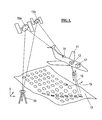
- a surface aircraft 11 with a built-in 3D measuring device 12 is shown.
- This comprises a laser rangefinder which determines the respective distance from the time of flight (time-of-flight, ToF) of the emitted laser radiation 19.
- the 3D measuring device further has a beam deflecting device which deflects the laser beams 19 normal to the direction of flight, so that the overflown terrain 13 is scanned line by line with a measuring beam fan 18.
- the respective geographic coordinates of the aircraft 11 are determined by a satellite navigation system (GPS).
- GPS satellite navigation system
- a so-called differential GPS is used, in which the navigation system receives not only signals from several satellites 15a, 15b,..., But also from a fixed station 16.
- the attitude (course, roll and pitch angle) is measured by means of a gyroscope 17. All these data are stored for each measuring point. In conjunction with the measured distance and the deflection angle of the deflection so that the geographical data of the measuring points are determined. In their entirety, these give a 3D data set or a corresponding point cloud of the terrain 13.
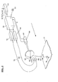
- Fig. 2 is shown schematically the structure of such an aircraft-based laser scanner.
- a central computer 56 which controls the individual components and links the distance values provided by the rangefinder with the scan angles, geographic coordinates and attitude angles and records these files.
- the output of the data sets can be done via a data carrier 57, for example a DVD.
- the central computer 56 drives a laser transmitter 30, which emits corresponding laser pulses.
- the laser radiation is fed through a fiber optic cable 58 to an optic 60.
- the rotating mirror pyramid 62 deflects the laser beam downwards and transversely to the direction of flight. In their entirety, the measuring beams form a fan of rays, which scans the area 13 like a line.
- the mirror pyramid is driven by a motor 64, which is controlled by the central computer 56. By an angle decoder 65 arranged on the motor shaft, the momentary adjustment of the mirror pyramid 62 is reported back to the computer 56.
- the laser radiation reflected from the target space is illuminated by the mirror pyramid 62 a lens 68 deflected and fed via a fiber optic cable 70 of the receiving stage 72.
- the echo pulses converted into electrical signals in the receiving stage are fed to the computer 56. From the running time (ToF) of the pulses, the corresponding distance values are calculated. These data are linked to the data supplied by the angle decoder 65, the DGPS 14 and the gyroscope 17. This data defines the geographic coordinates of each measurement point so that 3D terrain models can be calculated from the corresponding datasets.
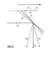
- the mirror pyramid is designed with mirror surfaces that enclose different angles with the axis of rotation.
- this principle is shown schematically: the axis of rotation of the mirror pyramid is denoted by 75, 3 mirror surfaces by 76 to 78.
- the mirror surface 76 includes the rotation axis at an angle of 45 °, 77 a larger, 78 a correspondingly smaller angle.
- the laser beam 79 is directed at the mirror surface 76 by 90 ° downwards (item 80).
- the mirror surface 78 of the measuring beam 81 is deflected forward, through the surface 77 to the rear (Pos. 82).
- When using a 3-sided mirror pyramid one forward rotation, one vertical downward and one backward directed fan beam is thus generated in one revolution.
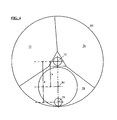
- a mirror pyramid 83 is shown in a projection in the direction of the axis of rotation 75.
- the individual surfaces 76 to 78 have different circumferential angles.
- the aperture of the laser beam 79 and the receiving beam 84 are shown.
- the optical axis of the laser transmitting beam has a much greater radial distance a from the axis of rotation 75 than the radial distance b of the optical axis of the receiving beam. This measure results in a significantly improved efficiency of the overall system.
- the Fig. 5 shows a variant of that in the Fig. 4 illustrated construction.
- the mirror pyramid 83 is the same in both figures.
- the receive beam is split into two beams 85 and 86, resulting in a slightly more favorable course of the energy of the reflected laser radiation during operation, which hits the receiving stage.
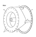
- a 3-sided mirror pyramid 86 is shown.
- the body of the pyramid is made of metal, for example of aluminum or magnesium or of corresponding alloys. Due to the asymmetrical design of the pyramid results in an uneven mass distribution, which can lead to disturbing vibrations especially at high speeds. It is therefore advantageous to balance the mirror pyramid dynamically.
- a plurality of holes 87 are provided in the base surface 88 of the pyramid 83, in which either weights can be filled, for example, pressed in lead weights, or which are drilled for local weight reduction.
- Such balance weights are alternatively or additionally provided in a further, arranged at an axial distance from the first plane second level, u.zw.
- the ring 89 preferably in the form of a ring 89, which is fastened with supports 90-92 to the mirror pyramid 83.
- the ring 89 also has a plurality of holes 87, which for Balance can be drilled individually or filled with weights.
- the supports 90-92 are, in order to reduce shadowing as far as possible, arranged in the extension or starting from the pyramid edges.
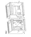
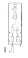
- a 3D measuring device in which the deflecting device with the rotating mirror pyramid 83 is arranged in a measuring head 94 which can be separated from the base device 93.
- the measuring head 94 comprises the rotating mirror pyramid 83 with the bearing, the associated drive motor 95, and an angle decoder 99.
- the measuring head 94 is connected to the base unit 93 with a multiple plug, not shown, and is controlled by a central computer arranged in the base unit 93. From the angle decoder 99 in the measuring head, the respective rotation angle is reported back to the computer.
- the base unit 93 in addition to the central computer and the laser rangefinder, including the associated evaluation device is housed.
- the measuring head 94 is oriented on the base unit 93.
- the two components 93 and 94 each have a window 97 and 98, which are aligned with each other in the assembled state.
- the windows 97 and 98 can have an optical effect and have a filter function and / or a corresponding refractive power.
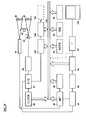
- the Fig. 10 schematically illustrates a laser rangefinder, as used in the device according to the invention.
- the beam deflection device by which the laser beam is deflected and the target area is scanned in a line.
- the laser rangefinder and the entire 3D measuring device are controlled by a micro-processor ( ⁇ P) 180.
- the rangefinder comprises a laser transmitter 181, which emits a laser pulse on a start pulse of the ⁇ P 180.
- the laser radiation is focused by an objective 182 to a preselected distance.
- the radiation reflected from objects in the target area is concentrated by a lens 183 onto a photosensitive diode 184, such as an avalanche diode.
- a small portion of the radiation emitted by the laser 181 radiation is fed directly to the receiving diode 184.
- This pulse which is received substantially simultaneously with the emission of the laser pulse, serves to determine the pulse transit time (time-of-flight, ToF) and thus the distance as a start signal for the time measurement.
- the output of the receiving diode 184 is amplified in an amplifier 186 and optionally filtered and finally digitized in an A / D converter 187.
- the A / D converter 187 and also the ⁇ P 180 are clocked by a pulse or clock generator 188.
- Output signals of the A / D converter 187 are fed to a counter stage 189, in which the number of clock pulses between the start pulse and the Receive pulse is determined. From the pulse number, the ToF is determined in the step 190 and, as a result, the distance between the range finder and the target is determined. However, the distance value calculated in this way has a relatively low accuracy.
- An advantage of this strategy is on the other hand, that the computational effort is very low and thus the computing time is minimal, so that the rangefinder can be operated at a very high clock rate.
- the ⁇ P 180 communicates with the other components of the system via a data bus 191.
- the software required to operate the ⁇ Ps 180 is stored in the program memory 192.
- the target area is detected only 2-dimensionally by the laser range finder in conjunction with the deflecting device, it is necessary for the acquisition of a 3D image to move the 3D surveying device in a translatory manner over the target area. For this it is necessary to define all degrees of freedom of the respective measuring beam in the room with high accuracy.
- To detect the geographical coordinates x, y and z and the course angle ⁇ is a satellite-based navigation system GPS. If, in addition to the various satellites, a fixed, terrestrial station is used for the measurement, an extremely high accuracy can be achieved. (Differential GPS - DGPS, block 193).
- the 3D surveying device can be arranged in the aircraft, for example on a gyro-stabilized platform, but in general it is more appropriate to derive the roll angle ⁇ , the pitch angle ⁇ and flight path angle y from a gyroscope (INS) 194.
- the position of the measuring beam is further defined by the beam deflecting device, namely in the device according to the invention in two different directions: for example, has the rotating mirror pyramid used for beam deflection, as in Fig. 3 schematically illustrated, three surfaces, each including a different angle with the axis of rotation, so depending on the corresponding angle sector, a scanning fan will be directed backwards, vertically downwards or forwards.
- the beam angle within the scanning fan determines the exact rotational angle ⁇ of the mirror pyramid.
- the respective rotation angle ⁇ is measured by an angle decoder 195 arranged on the rotation axis of the mirror pyramid, and by the ⁇ P 180 the fan angles and the beam angles within the compartments are determined.
- stage 196 the geographic coordinates of the measuring equipment and the various angles are linked to the simultaneously measured distance values and from this the geographical coordinates of the individual measuring points are determined. These data are stored in a data memory 197.
- the memory 197 can be connected to a PC on whose monitor 102 the measured terrain can then be checked on-line in a foresight on board the aircraft for completeness, etc.
- the stream of sampling pulses coming from the A / D converter 187 is fed to the stage 103, in which each individual measurement of the rangefinder is assigned the associated coordinates of the measuring device and the corresponding angle data.
- the data sets generated in this way are stored in a memory 104 and can be transferred to an external data carrier 106 via an interface 105 for off-line processing with high accuracy.
- the arithmetic unit 107 comprises a first data memory 108, in which the data coming from the data carrier 106 are stored.
- step 109 taking the pulse shape and amplitude into account, the temporal position of the corresponding pulse with respect to the scanner is determined from the sampling pulses.
- step 112 the time difference between the start and echo pulses and hence the distance to the target in question is calculated from these data with high accuracy. From this distance value, the geographic coordinates of the measuring device and the associated angle values, the geographical coordinates of the objects in the target area are defined.
- the corresponding measurement points describe a 3D data set or a point cloud. Since the data set or the corresponding point cloud is based on measurements from different directions, the resulting distance image is largely free of shadowing.
- the corresponding calculations are made by a ⁇ P 110 whose program memory is designated 111.
- a digital surface model (DSM) 113 can be generated, which can be further processed by known programs.
- the high-precision data processing can already be done on-line on board the aircraft, without having to accept a reduced measuring rate. In this case, it is unnecessary to generate a separate data record for the preview to control the measurement process.
- Planar mirrors are attached to this basic structure 100.
- the mirrors may be glued or bolted to the base structure 100. It may be appropriate to adjust the support points of the mirror adjustable. This construction is particularly suitable for irregular mirror pyramids or mirror prisms with different facet angles and / or a large facet number.
- a rangefinder can be used which emits a modulated laser beam, the transit time being determined from the phase relationship between the emitted and the echo signal.
- a rangefinder can be used which emits a modulated laser beam, the transit time being determined from the phase relationship between the emitted and the echo signal.
- the deflection device shown above with a mirror pyramid one with a mirror prism can also be used.
- aircraft-supported 3D surveying equipment is used again and again went out.
- these devices can be used with the same advantages in land vehicles, for example in rail vehicles. Advantages also arise when used on ships or boats, for the measurement of waterways and coastlines.
Landscapes
- Physics & Mathematics (AREA)
- Engineering & Computer Science (AREA)
- General Physics & Mathematics (AREA)
- Radar, Positioning & Navigation (AREA)
- Remote Sensing (AREA)
- Electromagnetism (AREA)
- Computer Networks & Wireless Communication (AREA)
- Optics & Photonics (AREA)
- Optical Radar Systems And Details Thereof (AREA)
- Length Measuring Devices By Optical Means (AREA)
Abstract
Description
Die Erfindung bezieht sich auf eine 3D-Vermessungseinrichtung mit einem Laser-Entfernungsmesser, der einen Laser-Sender umfasst, der gepulste bzw. modulierte Laser-Strahlung aussendet. Sie umfasst ferner eine Empfangseinrichtung, welche die von Zielen reflektierte Strahlung empfängt. Dem Laser-Sender und der Empfangseinrichtung ist je ein optisches System, insbesondere ein Objektiv vorgeschaltet. Der Laserentfernungsmesser verfügt über eine Auswerteeinrichtung, durch welche aus der Laufzeit der Laserimpulse bzw. aus der Phasenlage der modulierten Laser-Strahlung die Distanz zwischen dem Laser-Entfernungsmesser und den Zielen ermittelt wird. Weiters ist eine Ablenkeinrichtung für die Sende- und Empfangsstrahlen vorgesehen, welche mindestens ein um eine Achse rotierendes Spiegelprisma, bzw. eine rotierende Spiegelpyramide umfasst, mittels welchem bzw. welcher der Zielraum mit einem Strahlenfächer abtastbar ist und die gesamte 3D-Vermessungseinrichtung relativ in Bezug auf den Zielraum translatorisch und im Wesentlichen normal zum Strahlenfächer bewegbar ist, so dass vom Zielraum ein 3D-Datensatz bzw. eine entsprechende Punktwolke erzeugt wird und zu jedem Messpunkt die Entfernung, der Ablenkwinkel und die geografischen Koordinaten sowie die räumliche Lage der 3D-Vermessungseinrichtung erfasst und in einem Datenspeicher abgelegt werden.The invention relates to a 3D measuring device with a laser rangefinder, which comprises a laser transmitter which emits pulsed or modulated laser radiation. It also comprises a receiving device which receives the radiation reflected by targets. The laser transmitter and the receiving device are each preceded by an optical system, in particular a lens. The laser rangefinder has an evaluation device, by means of which the distance between the laser rangefinder and the targets is determined from the transit time of the laser pulses or from the phase position of the modulated laser radiation. Furthermore, a deflection device is provided for the transmitting and receiving beams, which comprises at least one mirror prism rotating about an axis, or a rotating mirror pyramid, by means of which or which the target space can be scanned with a beam fan and the entire 3D measuring device relative to the target space is translationally and substantially normal to the fan beam movable so that the target space a 3D data set or a corresponding point cloud is generated and for each measurement point, the distance, the deflection angle and the geographical coordinates and the spatial position of the 3D-surveying detected and be stored in a data store.
Solche Bilderfassungssysteme werden beispielsweise in Fluggeräten, wie Flächenflugzeugen, Hubschraubern oder auch in unbemannten Drohnen eingesetzt und dienen der Vermessung von mehr oder weniger großen Landstrichen. Als Ergebnis wird ein 3D-Datensatz bzw. ein digitales Oberflächenmodell generiert, welcher bzw. welches mit bekannten CAD-Programmen weiter bearbeitet werden kann. Die Ergebnisse dieser Vermessung sind nicht immer einfach zu interpretieren, da alle Elemente, die sich in der Richtung der Messstrahlen erstrecken nicht deutlich wiedergegeben werden. So ist es beispielsweise relativ schwierig, in einem solchen Modell Hochspannungsmaste, Schornsteine oder auch Vertiefungen wie Gletscherspalten oder Lawinenabrisse auszumachen.Such image acquisition systems are used, for example, in aircraft such as surface aircraft, helicopters or in unmanned drones and serve the measurement of more or less large tracts of land. As a result, a 3D data set or a digital surface model is generated, which or which can be further processed with known CAD programs. The results of this survey are not always easy to interpret, as all elements that extend in the direction of the measuring beams are not clearly reproduced. For example, it is relatively difficult in To identify such a model high-voltage masts, chimneys or wells such as crevasses or avalanches.
Um diese Schwierigkeiten zu vermeiden, ist bereits vorgeschlagen worden, mehrere gleichartige 3D-Vermessungseinrichtungen vorzusehen, die das Terrain unter unterschiedlichen Winkeln erfassen und die jeweiligen 3D-Datensätze bzw. Punktwolken zu einem einzigen Datensatz bzw. zu einer einzigen Punktwolke zu kombinieren, der bzw. die dann ein weitgehend abschattungsfreies Oberflächenmodell ergibt.To avoid these difficulties, it has already been proposed to provide a plurality of similar 3D surveying devices which detect the terrain at different angles and to combine the respective 3D data records or point clouds into a single data set or to a single point cloud which which then gives a largely shading-free surface model.
Eine solche Lösung weist aber nicht nur den Nachteil einer wesentlich höheren Investition auf, bei vielen Anwendungen, insbesondere bei airborne-Einsätzen, stellen auch das wesentlich höhere Gewicht und der deutlich höhere Energieverbrauch ein Problem dar.However, such a solution not only has the disadvantage of a much higher investment, in many applications, especially in airborne applications, also represent the much higher weight and significantly higher energy consumption is a problem.
Um die Nachteile der bekannten Lösungen zu vermeiden, wird erfindungsgemäß vorgeschlagen, dass mindestens eine der Flächen der Spiegelpyramide sowie eine benachbarte Spiegelfläche mit der Rotationsachse unterschiedliche Winkel einschließen. Zumindest zwei Messstrahlenfächer tasten das Zielgebiet aus verschiedenen Winkeln zeilenförmig ab, wobei die Zeilen von Messpunkten, die sich aus den verschiedenen Winkeln der Spiegelflächen ergeben, in Richtung der translatorischen Bewegung der 3D-Vermessungseinrichtung versetzt sind und unter Berücksichtigung des Winkels der Spiegelflächen und den sich daraus ergebenden unterschiedlichen Aufnahmerichtungen sowie des Drehwinkels der Spiegelpyramide die Lage, Richtung und Länge des Messstrahles und damit die geografischen Koordinaten der Messpunkte im Zielraum definiert sind und die Gesamtheit der Messpunkte einen 3D-Datensatz bzw. eine Punktwolke repräsentieren, in welchem bzw. in welcher durch die verschiedenen Aufnahmerichtungen Abschattungen weitgehend vermieden sind.To avoid the disadvantages of the known solutions, the invention proposes that at least one of the surfaces of the mirror pyramid and an adjacent mirror surface with the axis of rotation include different angles. At least two measuring beam scanners line scan the target area from different angles, the lines of measuring points resulting from the different angles of the mirror surfaces being offset in the direction of the translational movement of the 3D surveying device and taking into account the angle of the mirror surfaces and the resulting the position, direction and length of the measuring beam and thus the geographical coordinates of the measuring points are defined in the target space and the totality of the measuring points represent a 3D data set or a point cloud, in which or in which by the different shooting directions shading are largely avoided.
Vorteilhaft ist das vom Laser-Sendestrahl in den Empfangskanal durch Reflexionen etc. eingestreute Licht des Sendeimpulses von der Auswerteeinrichtung bezüglich der zeitlichen Lage des Impulses verarbeitbar und als Startsignal für die Zeitmessung zwischen Aussenden des Laserimpulses und Empfang der EchoImpulse nutzbar.Advantageously, the light emitted by the laser transmission beam into the reception channel through reflections, etc., of the transmission pulse from the evaluation device is in relation to the temporal position The pulse can be processed and used as a start signal for the time measurement between transmission of the laser pulse and reception of the EchoImpulse.
In einer anderen Variante der Erfindung werden die innerhalb einer vorgegebenen minimalen Zeitspanne eintreffenden Echoimpulse bei der Auswertung nicht berücksichtigt, wobei die minimale Zeitspanne so gewählt ist, dass im Bereich der 3D-Vermessungseinrichtung gestreutes Laser-Sendelicht mit Sicherheit bei der Zeitmessung ausgeklammert bleibt.In another variant of the invention, the echo pulses arriving within a predetermined minimum time interval are not taken into account in the evaluation, wherein the minimum time span is chosen such that scattered laser transmission light in the area of the 3D surveying device certainly remains excluded from the time measurement.
Zur Erzielung einer hohen Scan-Rate rotieren die Spiegelpyramiden mit einer sehr hohen Geschwindigkeit. Durch den unsymmetrischen Aufbau der Spiegelpyramide können Unwuchten entstehen, die im Betrieb zu Vibrationen führen könnten. Es ist daher günstig, die Spiegelpyramide zu wuchten. Zu diesem Zweck wird im Bereich der Basis und/oder der Deckfläche des Pyramidenstumpfes je ein Ring vorgesehen, welche Ringe zur insbesondere dynamischen Wuchtung lokal in ihrer Masse veränderbar sind.To achieve a high scan rate, the mirror pyramids rotate at a very high speed. Due to the asymmetrical structure of the mirror pyramid imbalances can arise, which could lead to vibrations during operation. It is therefore beneficial to balance the mirror pyramid. For this purpose, a ring is provided in the region of the base and / or the top surface of the truncated pyramid, which rings are locally variable in their mass for dynamic particular balancing.
Um Beschneidungen von Sende- bzw. Empfangskanal zu vermeiden, sind die Abstützungen des oben genannten Ringes an den Schnittkanten der Spiegelfacetten angeordnet.In order to avoid clipping of the transmitting or receiving channel, the supports of the above-mentioned ring are arranged at the cut edges of the mirror facets.
Um die zur Empfangseinrichtung gelangende Energie der von den Zielen reflektierten Laserstrahlung zu optimieren, wird in einer vorteilhaften Ausgestaltung der Erfindung die optische Achse der Empfangseinrichtung in einer Normalebene zur Rotationsachse der Spiegelpyramide in Abhängigkeit von der Scan-Rate und/oder der jeweils gemessenen Entfernung verstellt.In order to optimize the energy reaching the receiving device of the laser radiation reflected from the targets, in an advantageous embodiment of the invention, the optical axis of the receiving device is adjusted in a normal plane to the axis of rotation of the mirror pyramid depending on the scan rate and / or the respective measured distance.
Zu diesem Zweck ist zwischen der Empfangseinrichtung und der Spiegelpyramide ein schwenkbarer Spiegel vorgesehen, dessen Schwenkachse parallel zur Rotationsachse der Spiegelpyramide verläuft und dessen Antrieb den Spiegel in Abhängigkeit von der Scan-Rate und/oder der jeweils gemessenen Entfernung verschwenkt.For this purpose, a pivotable mirror is provided between the receiving device and the mirror pyramid, the pivot axis of which runs parallel to the axis of rotation of the mirror pyramid and whose drive pivots the mirror as a function of the scan rate and / or the respectively measured distance.
In einer anderen Variante der Erfindung ist die Empfangseinrichtung verschiebbar angeordnet, wobei der Verstellantrieb beispielsweise ein Piezo-Element umfasst.In another variant of the invention, the receiving device is arranged displaceably, wherein the adjusting drive comprises, for example, a piezoelectric element.
Je nach Einsatz der 3D-Vermessungseinrichtung ergeben sich unterschiedliche Auslegungen insbesondere der Ablenkeinrichtung. So wird beispielsweise bei einer Vermessung aus geringer Flughöhe ein Strahlenfächer mit einem großen Winkel erforderlich sein, während bei einer Vermessung aus größerer Höhe Strahlenfächer mit einem vergleichsweise kleinen Winkel notwendig sind, um einen optimalen Abstand zwischen den Messpunkten zu erhalten. Um diese Bedingungen zu erfüllen, kann die Spiegelpyramide im ersteren Fall Spiegelflächen aufweisen, die einen großen Winkel überdecken. Bevorzugt werden zu diesem Zweck 3-seitige Pyramiden eingesetzt, während für Aufnahmen aus größerer Höhe Pyramiden mit einer wesentlich größeren Anzahl von Spiegelflächen zum Einsatz kommen. Parallel hierzu kann auch die Scan-Rate bzw. die Drehzahl der Spiegelpyramide dem jeweiligen Einsatz angepasst werden.Depending on the use of the 3D measuring device, different designs result, in particular the deflection device. Thus, for example, in a measurement from low altitudes, a fan beam with a large angle will be required, while in a measurement from a greater height beam fans with a comparatively small angle are necessary to obtain an optimal distance between the measurement points. To meet these conditions, the mirror pyramid in the former case may have mirror surfaces that cover a large angle. Preferably 3-sided pyramids are used for this purpose, while for shooting from a greater height pyramids come with a much larger number of mirror surfaces are used. Parallel to this, the scan rate or the speed of the mirror pyramid can be adapted to the respective application.
Um zu vermeiden, dass für jede dieser Anwendungen ein spezielles Gerät angeschafft werden muss, wird erfindungsgemäß vorgeschlagen, die 3D-Vermessungseinrichtung in ein Basisgerät und einen auswechselbaren Messkopf, der die Ablenkeinrichtung, insbesondere die Spiegelpyramide enthält, zu teilen.In order to avoid that a special device must be purchased for each of these applications, the invention proposes to divide the 3D measuring device into a base device and an exchangeable measuring head which contains the deflection device, in particular the mirror pyramid.
Vorzugsweise enthält der Messkopf die Lagerung, einen Antriebsmotor und einen Winkeldecoder für die Spiegelpyramide und ist über elektrische Steckverbindungen mit dem Basisgerät verbindbar.Preferably, the measuring head includes the bearing, a drive motor and an angle decoder for the mirror pyramid and can be connected via electrical connectors to the base unit.
In einer vorteilhaften Weiterentwicklung der Erfindung weisen das Basisgerät und der Messkopf je ein für die Laser-strahlung transparentes Fenster auf, die sich bei am Basisgerät montiertem Messkopf gegenüberliegen, so dass die Strahlung des im Basisgerät angeordneten Laser-Senders in den Messkopf eintreten und die von den Zielen reflektierte und im Messkopf abgelenkte Strahlung durch die beiden Fenster auf die im Basisgerät befindliche Empfangseinrichtung gelangen kann.In an advantageous further development of the invention, the base unit and the measuring head each have a window transparent to the laser radiation, which are located opposite the measuring head mounted on the base unit, so that the radiation of the laser transmitter arranged in the base unit enters the measuring head and that of The radiation reflected by the targets and deflected in the measuring head can pass through the two windows onto the receiving device located in the base unit.
In einer zweckmäßigen Ausführung schließen die Fenster das Basisgerät und den Messkopf dicht, insbesondere gasdicht ab und weisen eine optische Wirkung auf und wirken beispielsweise als Linsen bzw. Filter.In an expedient embodiment, the windows close the base unit and the measuring head tightly, in particular gas-tight, and have an optical effect and act, for example, as lenses or filters.
Im Interesse einer optimalen Auslegung der einzelnen Spiegelflächen umfasst die Spiegelpyramide einen insbesondere metallischen Grundkörper und daran befestigte Spiegel, wobei der Grundkörper exakt positionierte, gegebenenfalls justierbare Aufnahmen für die einzelnen Spiegel aufweist.In the interest of an optimal design of the individual mirror surfaces, the mirror pyramid comprises a particular metallic base body and mirror attached thereto, wherein the base body has precisely positioned, optionally adjustable recordings for the individual mirrors.
Weitere Merkmale der Erfindung ergeben sich aus der anschließenden Beschreibung einiger Ausführungsbeispiele und unter Bezugnahme auf die Zeichnungen:
-
Fig. 1 zeigt schematisch eine konventionelle, flugzeuggestützte (airborne) 3D-Vermessungseinrichtung im Einsatz. -
Fig. 2 veranschaulicht ebenfalls schematisch die verschiedenen Komponenten dieser Einrichtung. -
Fig. 3 ist eine Prinzipdarstellung der erfindungsgemäßen Ablenkeinrichtung.
-
Fig. 1 schematically shows a conventional airborne 3D surveying device in use. -
Fig. 2 also schematically illustrates the various components of this device. -
Fig. 3 is a schematic diagram of the deflection device according to the invention.
Die
Die
Die
Die
In den
Die
In der
Der Zentralrechner 56 steuert einen Lasertransmitter 30 an, der entsprechende Laser-Impulse aussendet. Die Laser-Strahlung wird durch ein Glasfaserkabel 58 einer Optik 60 zugeführt. Durch die rotierende Spiegelpyramide 62 wird der Laserstrahl nach unten und quer zur Flugrichtung abgelenkt. In ihrer Gesamtheit bilden die Messstrahlen einen Strahlenfächer, der das Gelände 13 zeilenartig abtastet. Angetrieben wird die Spiegelpyramide durch einen Motor 64, der durch den Zentralrechner 56 gesteuert wird. Durch einen auf der Motorwelle angeordneten Winkeldecoder 65 wird die Momentanstellung der Spiegelpyramide 62 an den Rechner 56 zurückgemeldet. Die vom Zielraum reflektierte Laser-Strahlung wird durch die Spiegelpyramide 62 auf ein Objektiv 68 umgelenkt und über ein Glasfaserkabel 70 der Empfangsstufe 72 zugeführt. Die in der Empfangsstufe in elektrische Signale umgewandelten Echoimpulse werden dem Rechner 56 zugeführt. Aus der Laufzeit (ToF) der Impulse werden die entsprechenden Entfernungswerte berechnet. Diese Daten werden mit den vom Winkeldecoder 65, vom DGPS 14 und dem Kreiselgerät 17 gelieferten Daten verknüpft. Durch diese Daten werden die geografischen Koordinaten jedes Messpunktes definiert, so dass aus den entsprechenden Datensätzen 3D-Geländemodelle berechnet werden können.The
Wie bereits eingangs erwähnt, weisen solche Bilderfassungssysteme den Nachteil auf, dass es bei der Aufzeichnung zu Abschattungen kommt, so dass vertikal verlaufende Flächen oder auch bestimmte Bauwerke wie Schornsteine, Türme und Hochspannungsmaste sowie Spalten und Klüfte schwer zu interpretieren sind.As already mentioned, such imaging systems have the disadvantage that shading occurs during recording, so that vertically extending surfaces or even certain structures such as chimneys, towers and high-voltage masts, as well as crevices and gaps, are difficult to interpret.
Diese Probleme werden dadurch vermieden, dass Messungen in mindestens 2 Richtungen durchgeführt werden, beispielsweise senkrecht nach unten und nach vorne und/oder nach hinten. Zu diesem Zweck wird die Spiegelpyramide mit Spiegelflächen ausgeführt, die mit der Rotationsachse unterschiedliche Winkel einschließen. In
Es ist zu beachten, daß der hier verwendete Begriff "Pyramide" jeweils sowohl spitze als auch stumpfe Pyramiden ("Pyramidenstumpfe") und mit diesen äquivalente Formen, wie Prismen mit geneigten Seiten, umfaßt.It should be noted that the term "pyramid" used here in each case both pointed and blunt pyramids ("pyramid blunt") and with these equivalent forms, such as prisms with inclined sides.
In
Die
In den
In den
Mit Passstiften 96 wird der Messkopf 94 am Basisgerät 93 orientiert. Die beiden Komponenten 93 und 94 weisen je ein Fenster 97 und 98 auf, die im montierten Zustand miteinander fluchten. Die Fenster 97 und 98 können eine optische Wirkung aufweisen und eine Filterfunktion und/oder eine entsprechende Brechkraft besitzen. Durch die Teilung der 3D-Vermessungseinrichtung in zwei wechselbare Komponenten ist es möglich, diese an die unterschiedlichen Anforderungen der verschiedenen Messeinsätze anzupassen. So wird bei flugzeuggestützten Anwendungen bei geringen Flughöhen mit Vorteil eine 3- oder 4-seitige Spiegelpyramide eingesetzt, bei größeren Flughöhen hingegen eine 6-oder 8-seitige. Die Motordrehzahl muss ebenfalls dem jeweiligen Einsatzfall angepasst werden. Es können auch Spiegelpyramiden mit anderen Flächenwinkeln eingesetzt werden.With alignment pins 96, the measuring
Die Funktion eines Ausführungsbeispieles wird an Hand der Blockschaltbilder einer flugzeuggestützten (airborne) 3D-Vermessungseinrichtung gemäß den
Die
Der µP 180 kommuniziert mit den anderen Komponenten des Systems über einen Datenbus 191. Die zum Betrieb des µPs 180 erforderlichen Software ist in dem Programmspeicher 192 abgelegt.The μP 180 communicates with the other components of the system via a data bus 191. The software required to operate the μPs 180 is stored in the program memory 192.
Da durch den Laserentfernungsmesser in Verbindung mit der Ablenkeinrichtung das Zielgebiet nur 2-dimensional erfasst wird, ist es für die Aufnahme eines 3D-Bildes erforderlich, die 3D-Vermessungseinrichtung translatorisch über das Zielgebiet zu bewegen. Dazu ist es notwendig, sämtliche Freiheitsgrade des jeweiligen Messstrahles im Raum mit hoher Genauigkeit zu definieren. Zur Erfassung der geografischen Koordinaten x, y und z sowie des Kurswinkels ω dient ein satellitengestützes Navigationssystem GPS. Wird neben den verschiedenen Satelliten eine ortsfeste, terrestrische Station zur Messung herangezogen, so kann eine extrem hohe Genauigkeit erzielt werden. (Differential GPS - DGPS, Block 193).Since the target area is detected only 2-dimensionally by the laser range finder in conjunction with the deflecting device, it is necessary for the acquisition of a 3D image to move the 3D surveying device in a translatory manner over the target area. For this it is necessary to define all degrees of freedom of the respective measuring beam in the room with high accuracy. To detect the geographical coordinates x, y and z and the course angle ω is a satellite-based navigation system GPS. If, in addition to the various satellites, a fixed, terrestrial station is used for the measurement, an extremely high accuracy can be achieved. (Differential GPS - DGPS, block 193).
Die 3D-Vermessungseinrichtung kann im Fluggerät beispielsweise auf einer kreiselstabilisierten Plattform angeordnet sein, im Allgemeinen ist es jedoch zweckmäßiger, den Rollwinkel ϕ, den Pitchwinkel Θ und Flugpfadwinkel y von einem Kreiselgerät (INS) 194 abzuleiten. Die Lage des Messstrahles wird ferner durch die Strahlablenkeinrichtung definiert, und zwar bei der erfindungsgemäßen Einrichtung in zwei verschiedenen Richtungen: weist beispielsweise die zur Strahlablenkung eingesetzte rotierende Spiegelpyramide, wie in
In der Stufe 196 werden die geografischen Koordinaten der Messeinrichtung und die verschiedenen Winkel mit den gleichzeitig gemessenen Entfernungswerten verknüpft und daraus die geografischen Koordinaten der einzelnen Messpunkte ermittelt. Diese Daten werden in einem Datenspeicher 197 abgelegt. Der Speicher 197 kann mit einem PC verbunden werden, auf dessen Monitor 102 dann on-line das vermessene Terrain in einer Vorausschau an Bord des Luftfahrzeuges auf Vollständigkeit etc. kontrolliert werden kann.In stage 196, the geographic coordinates of the measuring equipment and the various angles are linked to the simultaneously measured distance values and from this the geographical coordinates of the individual measuring points are determined. These data are stored in a data memory 197. The memory 197 can be connected to a PC on whose
Der vom A/D-Wandler 187 kommende Strom von Abtastimpulsen wird der Stufe 103 zugeleitet, in welcher jeder Einzelmessung des Entfernungsmessers die zugehörigen Koordinaten der Messeinrichtung und die entsprechenden Winkeldaten zugeordnet werden. Die auf diese Weise erzeugten Datensätze werden in einem Speicher 104 abgelegt und können über eine Schnittstelle 105 zu einer off-line Verarbeitung mit hoher Genauigkeit auf einen externen Datenträger 106 übertragen werden.The stream of sampling pulses coming from the A / D converter 187 is fed to the
Diese off-line Verarbeitung kann mit einer elektronischen Recheneinheit 107 durchgeführt werden, deren Blockschaltbild schematisch in der
Aus den in der Stufe 112 berechneten Daten kann ein digitales Oberflächenmodell (Digital Surface Model, DSM) 113 generiert werden, welches mit bekannten Programmen weiter bearbeitet werden kann.From the data calculated in
Stehen Rechner mit sehr hoher Leistungsfähigkeit und hoher Rechengeschwindigkeit zur Verfügung, kann die hochpräzise Datenverarbeitung bereits on-line an Bord des Luftfahrzeuges erfolgen, ohne eine reduzierte Messrate in Kauf nehmen zu müssen. In diesem Fall erübrigt es sich, für die Vorschau zur Kontrolle des Messvorganges einen eigenen Datensatz zu generieren.If computers with very high performance and high computing speed are available, the high-precision data processing can already be done on-line on board the aircraft, without having to accept a reduced measuring rate. In this case, it is unnecessary to generate a separate data record for the preview to control the measurement process.
In den
Sie besteht aus einer Grundstruktur 100 aus Metall, insbesondere Aluminium oder Magnesium, aus Keramik oder faserverstärktem Kunststoff. Auf dieser Grundstruktur 100 werden Planspiegel befestigt. Die Spiegel können aufgeklebt oder mit der Grundstruktur 100 verschraubt sein. Es kann zweckmäßig sein, die Auflagerpunkte der Spiegel justierbar auszuführen. Diese Konstruktion ist besonders geeignet für irreguläre Spiegelpyramiden bzw. Spiegelprismen mit unterschiedlichen Facettenwinkeln und/oder einer großen Facettenzahl.It consists of a
Die Erfindung ist nicht auf die oben beschriebenen Ausführungsbeispiele beschränkt, sondern kann in verschiedener Weise modifiziert werden, ohne den Rahmen der Erfindung zu verlassen. So kann anstelle des oben beschriebenen Entfernungsmessers mit Laserimpulsen ein Entfernungsmesser eingesetzt werden, welcher einen modulierten Laserstrahl aussendet, wobei die Laufzeit aus der Phasenlage zwischen dem ausgesandten und dem Echosignal ermittelt wird. Anstelle der oben gezeigten Ablenkeinrichtung mit einer Spiegelpyramide kann auch eine solche mit einem Spiegelprisma eingesetzt werden.The invention is not limited to the embodiments described above, but can be modified in various ways without departing from the scope of the invention. Thus, instead of the rangefinder described above with laser pulses, a rangefinder can be used which emits a modulated laser beam, the transit time being determined from the phase relationship between the emitted and the echo signal. Instead of the deflection device shown above with a mirror pyramid, one with a mirror prism can also be used.
In der obigen Beschreibung verschiedener Ausführungsbeispiele wird immer wieder von flugzeuggestützten 3D-Vermessungseinrichtungen ausgegangen. Diese Einrichtungen können aber mit den gleichen Vorteilen in Landfahrzeugen, beispielsweise in schienengebundenen Fahrzeugen zur Anwendung kommen. Vorteile ergeben sich auch beim Einsatz auf Schiffen oder Booten, zur Vermessung von Wasserstraßen und Küstenverläufen.In the above description of various embodiments, aircraft-supported 3D surveying equipment is used again and again went out. However, these devices can be used with the same advantages in land vehicles, for example in rail vehicles. Advantages also arise when used on ships or boats, for the measurement of waterways and coastlines.
Claims (16)
einem Laser-Entfernungsmesser, der einen Laser-Sender (30, 181) zum Aussenden eines Sendestrahls (19, 66) auf ein Ziel (13), eine Laser-Empfangseinrichtung (72, 184) zum Empfangen des vom Ziel reflektierten Empfangsstrahls (19, 66) und eine Auswerteeinrichtung (56, 107, 180) zur Strahl-Laufzeitmessung umfaßt, um daraus die Zielentfernung zu messen, und
einer Ablenkeinrichtung (62, 83, 100) für die Sende- und Empfangsstrahlen (19, 66), die eine um eine Achse (75) rotierbare Spiegelpyramide (62, 83, 100) umfaßt, mittels welcher ein Raum von Zielen (13) mit zumindest einem Laserstrahlfächer (18) abtastbar ist, um aus den gemessenen Zielentfernungen eine 3D-Punktewolke (113) des Zielraums zu erstellen,
dadurch gekennzeichnet,
daß die Flächen (76-78) der Spiegelpyramide (62, 83, 100) mit der Rotationsachse (75) zumindest zwei unterschiedliche Winkel einschließen.3D laser measuring device (12), with
a laser rangefinder comprising a laser transmitter (30, 181) for emitting a transmission beam (19, 66) to a target (13), laser receiving means (72, 184) for receiving the reception beam reflected from the target (19, 66) and an evaluation device (56, 107, 180) for beam transit time measurement in order to measure the target distance therefrom, and
a deflection device (62, 83, 100) for the transmit and receive beams (19, 66), which comprises a about an axis (75) rotatable mirror pyramid (62, 83, 100), by means of which a space of targets (13) at least one laser beam fan (18) is scanned to create from the measured target distances a 3D point cloud (113) of the target area,
characterized,
that the surfaces (76-78) of the mirror pyramid (62, 83, 100) with the rotation axis (75) include at least two different angles.
Applications Claiming Priority (1)
| Application Number | Priority Date | Filing Date | Title |
|---|---|---|---|
| AT0138209A AT508562B1 (en) | 2009-09-02 | 2009-09-02 | 3-D MEASUREMENT DEVICE |
Publications (3)
| Publication Number | Publication Date |
|---|---|
| EP2293013A2 true EP2293013A2 (en) | 2011-03-09 |
| EP2293013A3 EP2293013A3 (en) | 2012-09-19 |
| EP2293013B1 EP2293013B1 (en) | 2014-10-08 |
Family
ID=43086306
Family Applications (1)
| Application Number | Title | Priority Date | Filing Date |
|---|---|---|---|
| EP10450139.0A Active EP2293013B1 (en) | 2009-09-02 | 2010-09-02 | 3D laser measuring device |
Country Status (2)
| Country | Link |
|---|---|
| EP (1) | EP2293013B1 (en) |
| AT (1) | AT508562B1 (en) |
Cited By (18)
| Publication number | Priority date | Publication date | Assignee | Title |
|---|---|---|---|---|
| CN102518922A (en) * | 2011-12-12 | 2012-06-27 | 中国科学院长春光学精密机械与物理研究所 | Space remote sensor support frame made of carbon fiber composite |
| EP2562309A1 (en) * | 2011-08-22 | 2013-02-27 | Joseph Vögele AG | Road finisher with measuring device |
| US20130077083A1 (en) * | 2011-09-22 | 2013-03-28 | Shuichi Suzuki | Optical beam scanner and laser radar unit |
| JP2016070974A (en) * | 2014-09-26 | 2016-05-09 | 株式会社デンソー | Laser irradiation control device |
| AT517701A4 (en) * | 2016-04-15 | 2017-04-15 | Riegl Laser Measurement Systems Gmbh | laser scanner |
| JPWO2017065048A1 (en) * | 2015-10-16 | 2018-08-02 | コニカミノルタ株式会社 | Optical scanning type object detection device |
| CN108840244A (en) * | 2017-12-20 | 2018-11-20 | 江苏耐维思通科技股份有限公司 | A kind of intelligent travelling crane control assembly lifted automatically |
| CN109254286A (en) * | 2018-11-13 | 2019-01-22 | 武汉海达数云技术有限公司 | Airborne laser radar optical scanner |
| CN109444842A (en) * | 2019-01-04 | 2019-03-08 | 北京环境特性研究所 | A kind of electromagnetic characteristic of scattering data reconstruction method and device |
| CN110100189A (en) * | 2016-11-07 | 2019-08-06 | 布莱克菲尔德公司 | Fiber scanner at least two fibers |
| CN111141744A (en) * | 2019-12-31 | 2020-05-12 | 广州维思车用部件有限公司 | Lens detection device |
| EP3792653A1 (en) | 2019-09-12 | 2021-03-17 | Riegl Laser Measurement Systems GmbH | Laser scanner |
| CN113125439A (en) * | 2019-12-31 | 2021-07-16 | 南京璟一机器人工程技术有限公司 | Spring end face detection system and detection method thereof |
| CN113238240A (en) * | 2021-05-15 | 2021-08-10 | 李学刚 | Handheld range finder is used in house property survey and drawing |
| US20210364605A1 (en) * | 2020-05-19 | 2021-11-25 | Gm Cruise Holdings Llc | Polygon scanning mirror for lidar beam scanning |
| EP4063915A1 (en) * | 2021-03-25 | 2022-09-28 | RIEGL Laser Measurement Systems GmbH | Device for measuring an environment |
| CN115184742A (en) * | 2022-05-06 | 2022-10-14 | 宁波送变电建设有限公司 | Optical monitoring angle measuring instrument for transformer substation |
| EP4428566A1 (en) * | 2023-03-09 | 2024-09-11 | RIEGL Laser Measurement Systems GmbH | Laser scanner for scanning an environment around an axis |
Families Citing this family (1)
| Publication number | Priority date | Publication date | Assignee | Title |
|---|---|---|---|---|
| EP4006577A4 (en) * | 2019-08-07 | 2022-09-07 | Suteng Innovation Technology Co., Ltd. | Laser radar and smart sensing device |
Family Cites Families (4)
| Publication number | Priority date | Publication date | Assignee | Title |
|---|---|---|---|---|
| DE3217785C1 (en) * | 1982-05-12 | 1983-12-15 | Messerschmitt-Bölkow-Blohm GmbH, 8000 München | Optomechanical scanner |
| JP3908297B2 (en) * | 1996-03-19 | 2007-04-25 | 株式会社トプコン | Laser surveyor |
| AT413452B (en) * | 2003-11-18 | 2006-03-15 | Riegl Laser Measurement Sys | DEVICE FOR RECORDING AN OBJECT ROOM |
| JP2005291787A (en) * | 2004-03-31 | 2005-10-20 | Denso Corp | Distance detection device |
-
2009
- 2009-09-02 AT AT0138209A patent/AT508562B1/en active
-
2010
- 2010-09-02 EP EP10450139.0A patent/EP2293013B1/en active Active
Non-Patent Citations (1)
| Title |
|---|
| None |
Cited By (32)
| Publication number | Priority date | Publication date | Assignee | Title |
|---|---|---|---|---|
| EP2562309A1 (en) * | 2011-08-22 | 2013-02-27 | Joseph Vögele AG | Road finisher with measuring device |
| US9290894B2 (en) | 2011-08-22 | 2016-03-22 | Joseph Vogele Ag | Road paver with measuring device |
| US20130077083A1 (en) * | 2011-09-22 | 2013-03-28 | Shuichi Suzuki | Optical beam scanner and laser radar unit |
| EP2573580A3 (en) * | 2011-09-22 | 2013-05-01 | Ricoh Company, Ltd. | Optical beam scanner and laser radar unit |
| US8773644B2 (en) | 2011-09-22 | 2014-07-08 | Ricoh Company, Ltd. | Optical beam scanner and laser radar unit |
| CN102518922A (en) * | 2011-12-12 | 2012-06-27 | 中国科学院长春光学精密机械与物理研究所 | Space remote sensor support frame made of carbon fiber composite |
| JP2016070974A (en) * | 2014-09-26 | 2016-05-09 | 株式会社デンソー | Laser irradiation control device |
| JPWO2017065048A1 (en) * | 2015-10-16 | 2018-08-02 | コニカミノルタ株式会社 | Optical scanning type object detection device |
| EP3364229A4 (en) * | 2015-10-16 | 2018-10-31 | Konica Minolta, Inc. | Optical-scanning-type object detection device |
| WO2017177246A1 (en) * | 2016-04-15 | 2017-10-19 | Riegl Laser Measurement Systems Gmbh | Laser scanner |
| US11073616B2 (en) | 2016-04-15 | 2021-07-27 | Riegl Laser Measurement Systems Gmbh | Laser scanner |
| AT517701B1 (en) * | 2016-04-15 | 2017-04-15 | Riegl Laser Measurement Systems Gmbh | laser scanner |
| AT517701A4 (en) * | 2016-04-15 | 2017-04-15 | Riegl Laser Measurement Systems Gmbh | laser scanner |
| CN110100189A (en) * | 2016-11-07 | 2019-08-06 | 布莱克菲尔德公司 | Fiber scanner at least two fibers |
| CN108840244A (en) * | 2017-12-20 | 2018-11-20 | 江苏耐维思通科技股份有限公司 | A kind of intelligent travelling crane control assembly lifted automatically |
| CN109254286B (en) * | 2018-11-13 | 2024-05-28 | 武汉海达数云技术有限公司 | Airborne laser radar optical scanning device |
| CN109254286A (en) * | 2018-11-13 | 2019-01-22 | 武汉海达数云技术有限公司 | Airborne laser radar optical scanner |
| CN109444842A (en) * | 2019-01-04 | 2019-03-08 | 北京环境特性研究所 | A kind of electromagnetic characteristic of scattering data reconstruction method and device |
| CN109444842B (en) * | 2019-01-04 | 2020-09-25 | 北京环境特性研究所 | Target electromagnetic scattering characteristic data reconstruction method and device |
| EP3792653A1 (en) | 2019-09-12 | 2021-03-17 | Riegl Laser Measurement Systems GmbH | Laser scanner |
| WO2021047846A1 (en) | 2019-09-12 | 2021-03-18 | Riegl Laser Measurement Systems Gmbh | Laser scanner |
| CN111141744A (en) * | 2019-12-31 | 2020-05-12 | 广州维思车用部件有限公司 | Lens detection device |
| CN111141744B (en) * | 2019-12-31 | 2023-01-31 | 广州维思车用部件有限公司 | Lens detection device |
| CN113125439B (en) * | 2019-12-31 | 2023-11-07 | 南京景曜智能科技有限公司 | Spring end face detection system and detection method thereof |
| CN113125439A (en) * | 2019-12-31 | 2021-07-16 | 南京璟一机器人工程技术有限公司 | Spring end face detection system and detection method thereof |
| US20210364605A1 (en) * | 2020-05-19 | 2021-11-25 | Gm Cruise Holdings Llc | Polygon scanning mirror for lidar beam scanning |
| US12055660B2 (en) * | 2020-05-19 | 2024-08-06 | Gm Cruise Holdings Llc | Polygon scanning mirror for lidar beam scanning |
| EP4063915A1 (en) * | 2021-03-25 | 2022-09-28 | RIEGL Laser Measurement Systems GmbH | Device for measuring an environment |
| CN113238240A (en) * | 2021-05-15 | 2021-08-10 | 李学刚 | Handheld range finder is used in house property survey and drawing |
| CN115184742A (en) * | 2022-05-06 | 2022-10-14 | 宁波送变电建设有限公司 | Optical monitoring angle measuring instrument for transformer substation |
| CN115184742B (en) * | 2022-05-06 | 2024-06-04 | 宁波送变电建设有限公司 | Optical monitoring angle measuring instrument for transformer substation |
| EP4428566A1 (en) * | 2023-03-09 | 2024-09-11 | RIEGL Laser Measurement Systems GmbH | Laser scanner for scanning an environment around an axis |
Also Published As
| Publication number | Publication date |
|---|---|
| AT508562B1 (en) | 2011-02-15 |
| EP2293013B1 (en) | 2014-10-08 |
| AT508562A4 (en) | 2011-02-15 |
| EP2293013A3 (en) | 2012-09-19 |
Similar Documents
| Publication | Publication Date | Title |
|---|---|---|
| EP2293013B1 (en) | 3D laser measuring device | |
| DE3922086C1 (en) | ||
| DE102004050682B4 (en) | Device for recording an object space | |
| DE69419102T2 (en) | Obstacle avoidance system for helicopters and airplanes | |
| AT509180B1 (en) | OPTOELECTRONIC MEASURING SYSTEM | |
| AT412028B (en) | DEVICE FOR RECORDING AN OBJECT SPACE | |
| EP1342989A2 (en) | Method for the recording of an object space | |
| AT412032B (en) | METHOD FOR RECORDING AN OBJECT SPACE | |
| EP0634668B1 (en) | Radar apparatus for obstacle warning | |
| DE3731037A1 (en) | LASER IMAGING SYSTEM WITH DETECTOR LINE | |
| DE3887667T2 (en) | Radioelectric sensor for creating a radioelectric map of a landscape. | |
| DE69005106T2 (en) | ARRANGEMENT FOR CREATING OR DETERMINING THE LOCATION OF A MEASURING POINT. | |
| EP0406879B1 (en) | Method for extracting movement errors of a carrier transporting a coherent imaging radar system from radar raw data and device for carrying out this method | |
| DE102005015914A1 (en) | Combined laser height and ground speed measuring device | |
| EP0757259A1 (en) | Device for movement error compensation in a radar with synthetic aperture based on rotating antennas (ROSAR) in a helicopter | |
| DE102018113244B3 (en) | Method and apparatus for measuring vibrations of an object using a drone | |
| DE102011121115B4 (en) | Laser scanner and method for measuring target areas | |
| EP3443381B1 (en) | Laser scanner | |
| DE2850743C3 (en) | Method and device for measuring the deviation of the transmission beam from the optical axis of the receiving telescope in a lidar device | |
| DE60100611T2 (en) | Device for measuring room pollution | |
| DE10341893B4 (en) | Method for reducing the Doppler in a coherent pulse radar system and use of the method | |
| EP1329739A2 (en) | Device for the recording of an object space | |
| EP1012627B1 (en) | Optoelectronic measuring method and an optoelectronic measuring device | |
| DE102014216368B4 (en) | MULTI-ARM LIDAR SYSTEM | |
| WO1986001909A1 (en) | Optical system for compensating movement in line-scanners |
Legal Events
| Date | Code | Title | Description |
|---|---|---|---|
| PUAI | Public reference made under article 153(3) epc to a published international application that has entered the european phase |
Free format text: ORIGINAL CODE: 0009012 |
|
| AK | Designated contracting states |
Kind code of ref document: A2 Designated state(s): AL AT BE BG CH CY CZ DE DK EE ES FI FR GB GR HR HU IE IS IT LI LT LU LV MC MK MT NL NO PL PT RO SE SI SK SM TR |
|
| AX | Request for extension of the european patent |
Extension state: BA ME RS |
|
| PUAL | Search report despatched |
Free format text: ORIGINAL CODE: 0009013 |
|
| AK | Designated contracting states |
Kind code of ref document: A3 Designated state(s): AL AT BE BG CH CY CZ DE DK EE ES FI FR GB GR HR HU IE IS IT LI LT LU LV MC MK MT NL NO PL PT RO SE SI SK SM TR |
|
| AX | Request for extension of the european patent |
Extension state: BA ME RS |
|
| RIC1 | Information provided on ipc code assigned before grant |
Ipc: G01S 17/10 20060101ALI20120815BHEP Ipc: G01S 17/89 20060101ALI20120815BHEP Ipc: G01S 17/42 20060101ALI20120815BHEP Ipc: G02B 26/10 20060101ALI20120815BHEP Ipc: G02B 5/09 20060101ALI20120815BHEP Ipc: G02B 26/12 20060101ALI20120815BHEP Ipc: G01C 15/00 20060101AFI20120815BHEP |
|
| 17P | Request for examination filed |
Effective date: 20121218 |
|
| 17Q | First examination report despatched |
Effective date: 20130322 |
|
| REG | Reference to a national code |
Ref country code: DE Ref legal event code: R079 Ref document number: 502010008026 Country of ref document: DE Free format text: PREVIOUS MAIN CLASS: G01C0015000000 Ipc: G01S0007481000 |
|
| RIC1 | Information provided on ipc code assigned before grant |
Ipc: G02B 26/12 20060101ALI20131105BHEP Ipc: G01S 17/42 20060101ALI20131105BHEP Ipc: G02B 5/09 20060101ALI20131105BHEP Ipc: G01C 15/00 20060101ALI20131105BHEP Ipc: G01S 17/10 20060101ALI20131105BHEP Ipc: G01S 17/89 20060101ALI20131105BHEP Ipc: G02B 26/10 20060101ALI20131105BHEP Ipc: G01S 7/481 20060101AFI20131105BHEP |
|
| GRAP | Despatch of communication of intention to grant a patent |
Free format text: ORIGINAL CODE: EPIDOSNIGR1 |
|
| INTG | Intention to grant announced |
Effective date: 20140521 |
|
| GRAS | Grant fee paid |
Free format text: ORIGINAL CODE: EPIDOSNIGR3 |
|
| GRAA | (expected) grant |
Free format text: ORIGINAL CODE: 0009210 |
|
| AK | Designated contracting states |
Kind code of ref document: B1 Designated state(s): AL AT BE BG CH CY CZ DE DK EE ES FI FR GB GR HR HU IE IS IT LI LT LU LV MC MK MT NL NO PL PT RO SE SI SK SM TR |
|
| REG | Reference to a national code |
Ref country code: GB Ref legal event code: FG4D Free format text: NOT ENGLISH |
|
| REG | Reference to a national code |
Ref country code: AT Ref legal event code: REF Ref document number: 690916 Country of ref document: AT Kind code of ref document: T Effective date: 20141015 Ref country code: CH Ref legal event code: EP |
|
| REG | Reference to a national code |
Ref country code: IE Ref legal event code: FG4D Free format text: LANGUAGE OF EP DOCUMENT: GERMAN |
|
| REG | Reference to a national code |
Ref country code: DE Ref legal event code: R096 Ref document number: 502010008026 Country of ref document: DE Effective date: 20141120 |
|
| REG | Reference to a national code |
Ref country code: CH Ref legal event code: NV Representative=s name: PATWIL AG, CH |
|
| REG | Reference to a national code |
Ref country code: NL Ref legal event code: VDEP Effective date: 20141008 |
|
| REG | Reference to a national code |
Ref country code: LT Ref legal event code: MG4D |
|
| PG25 | Lapsed in a contracting state [announced via postgrant information from national office to epo] |
Ref country code: NL Free format text: LAPSE BECAUSE OF FAILURE TO SUBMIT A TRANSLATION OF THE DESCRIPTION OR TO PAY THE FEE WITHIN THE PRESCRIBED TIME-LIMIT Effective date: 20141008 |
|
| PG25 | Lapsed in a contracting state [announced via postgrant information from national office to epo] |
Ref country code: FI Free format text: LAPSE BECAUSE OF FAILURE TO SUBMIT A TRANSLATION OF THE DESCRIPTION OR TO PAY THE FEE WITHIN THE PRESCRIBED TIME-LIMIT Effective date: 20141008 Ref country code: LT Free format text: LAPSE BECAUSE OF FAILURE TO SUBMIT A TRANSLATION OF THE DESCRIPTION OR TO PAY THE FEE WITHIN THE PRESCRIBED TIME-LIMIT Effective date: 20141008 Ref country code: IS Free format text: LAPSE BECAUSE OF FAILURE TO SUBMIT A TRANSLATION OF THE DESCRIPTION OR TO PAY THE FEE WITHIN THE PRESCRIBED TIME-LIMIT Effective date: 20150208 Ref country code: NO Free format text: LAPSE BECAUSE OF FAILURE TO SUBMIT A TRANSLATION OF THE DESCRIPTION OR TO PAY THE FEE WITHIN THE PRESCRIBED TIME-LIMIT Effective date: 20150108 Ref country code: ES Free format text: LAPSE BECAUSE OF FAILURE TO SUBMIT A TRANSLATION OF THE DESCRIPTION OR TO PAY THE FEE WITHIN THE PRESCRIBED TIME-LIMIT Effective date: 20141008 Ref country code: PT Free format text: LAPSE BECAUSE OF FAILURE TO SUBMIT A TRANSLATION OF THE DESCRIPTION OR TO PAY THE FEE WITHIN THE PRESCRIBED TIME-LIMIT Effective date: 20150209 |
|
| PG25 | Lapsed in a contracting state [announced via postgrant information from national office to epo] |
Ref country code: SE Free format text: LAPSE BECAUSE OF FAILURE TO SUBMIT A TRANSLATION OF THE DESCRIPTION OR TO PAY THE FEE WITHIN THE PRESCRIBED TIME-LIMIT Effective date: 20141008 Ref country code: CY Free format text: LAPSE BECAUSE OF FAILURE TO SUBMIT A TRANSLATION OF THE DESCRIPTION OR TO PAY THE FEE WITHIN THE PRESCRIBED TIME-LIMIT Effective date: 20141008 Ref country code: PL Free format text: LAPSE BECAUSE OF FAILURE TO SUBMIT A TRANSLATION OF THE DESCRIPTION OR TO PAY THE FEE WITHIN THE PRESCRIBED TIME-LIMIT Effective date: 20141008 Ref country code: LV Free format text: LAPSE BECAUSE OF FAILURE TO SUBMIT A TRANSLATION OF THE DESCRIPTION OR TO PAY THE FEE WITHIN THE PRESCRIBED TIME-LIMIT Effective date: 20141008 Ref country code: HR Free format text: LAPSE BECAUSE OF FAILURE TO SUBMIT A TRANSLATION OF THE DESCRIPTION OR TO PAY THE FEE WITHIN THE PRESCRIBED TIME-LIMIT Effective date: 20141008 Ref country code: GR Free format text: LAPSE BECAUSE OF FAILURE TO SUBMIT A TRANSLATION OF THE DESCRIPTION OR TO PAY THE FEE WITHIN THE PRESCRIBED TIME-LIMIT Effective date: 20150109 |
|
| REG | Reference to a national code |
Ref country code: DE Ref legal event code: R097 Ref document number: 502010008026 Country of ref document: DE |
|
| PG25 | Lapsed in a contracting state [announced via postgrant information from national office to epo] |
Ref country code: DK Free format text: LAPSE BECAUSE OF FAILURE TO SUBMIT A TRANSLATION OF THE DESCRIPTION OR TO PAY THE FEE WITHIN THE PRESCRIBED TIME-LIMIT Effective date: 20141008 Ref country code: SK Free format text: LAPSE BECAUSE OF FAILURE TO SUBMIT A TRANSLATION OF THE DESCRIPTION OR TO PAY THE FEE WITHIN THE PRESCRIBED TIME-LIMIT Effective date: 20141008 Ref country code: CZ Free format text: LAPSE BECAUSE OF FAILURE TO SUBMIT A TRANSLATION OF THE DESCRIPTION OR TO PAY THE FEE WITHIN THE PRESCRIBED TIME-LIMIT Effective date: 20141008 Ref country code: EE Free format text: LAPSE BECAUSE OF FAILURE TO SUBMIT A TRANSLATION OF THE DESCRIPTION OR TO PAY THE FEE WITHIN THE PRESCRIBED TIME-LIMIT Effective date: 20141008 Ref country code: RO Free format text: LAPSE BECAUSE OF FAILURE TO SUBMIT A TRANSLATION OF THE DESCRIPTION OR TO PAY THE FEE WITHIN THE PRESCRIBED TIME-LIMIT Effective date: 20141008 |
|
| PLBE | No opposition filed within time limit |
Free format text: ORIGINAL CODE: 0009261 |
|
| STAA | Information on the status of an ep patent application or granted ep patent |
Free format text: STATUS: NO OPPOSITION FILED WITHIN TIME LIMIT |
|
| PG25 | Lapsed in a contracting state [announced via postgrant information from national office to epo] |
Ref country code: IT Free format text: LAPSE BECAUSE OF FAILURE TO SUBMIT A TRANSLATION OF THE DESCRIPTION OR TO PAY THE FEE WITHIN THE PRESCRIBED TIME-LIMIT Effective date: 20141008 |
|
| 26N | No opposition filed |
Effective date: 20150709 |
|
| PG25 | Lapsed in a contracting state [announced via postgrant information from national office to epo] |
Ref country code: SI Free format text: LAPSE BECAUSE OF FAILURE TO SUBMIT A TRANSLATION OF THE DESCRIPTION OR TO PAY THE FEE WITHIN THE PRESCRIBED TIME-LIMIT Effective date: 20141008 |
|
| PG25 | Lapsed in a contracting state [announced via postgrant information from national office to epo] |
Ref country code: LU Free format text: LAPSE BECAUSE OF FAILURE TO SUBMIT A TRANSLATION OF THE DESCRIPTION OR TO PAY THE FEE WITHIN THE PRESCRIBED TIME-LIMIT Effective date: 20150902 Ref country code: MC Free format text: LAPSE BECAUSE OF FAILURE TO SUBMIT A TRANSLATION OF THE DESCRIPTION OR TO PAY THE FEE WITHIN THE PRESCRIBED TIME-LIMIT Effective date: 20141008 |
|
| REG | Reference to a national code |
Ref country code: FR Ref legal event code: ST Effective date: 20160531 |
|
| PG25 | Lapsed in a contracting state [announced via postgrant information from national office to epo] |
Ref country code: IE Free format text: LAPSE BECAUSE OF NON-PAYMENT OF DUE FEES Effective date: 20150902 |
|
| PG25 | Lapsed in a contracting state [announced via postgrant information from national office to epo] |
Ref country code: FR Free format text: LAPSE BECAUSE OF NON-PAYMENT OF DUE FEES Effective date: 20150930 |
|
| REG | Reference to a national code |
Ref country code: AT Ref legal event code: MM01 Ref document number: 690916 Country of ref document: AT Kind code of ref document: T Effective date: 20150902 |
|
| PG25 | Lapsed in a contracting state [announced via postgrant information from national office to epo] |
Ref country code: AT Free format text: LAPSE BECAUSE OF NON-PAYMENT OF DUE FEES Effective date: 20150902 |
|
| PG25 | Lapsed in a contracting state [announced via postgrant information from national office to epo] |
Ref country code: MT Free format text: LAPSE BECAUSE OF FAILURE TO SUBMIT A TRANSLATION OF THE DESCRIPTION OR TO PAY THE FEE WITHIN THE PRESCRIBED TIME-LIMIT Effective date: 20141008 |
|
| PG25 | Lapsed in a contracting state [announced via postgrant information from national office to epo] |
Ref country code: HU Free format text: LAPSE BECAUSE OF FAILURE TO SUBMIT A TRANSLATION OF THE DESCRIPTION OR TO PAY THE FEE WITHIN THE PRESCRIBED TIME-LIMIT; INVALID AB INITIO Effective date: 20100902 Ref country code: SM Free format text: LAPSE BECAUSE OF FAILURE TO SUBMIT A TRANSLATION OF THE DESCRIPTION OR TO PAY THE FEE WITHIN THE PRESCRIBED TIME-LIMIT Effective date: 20141008 Ref country code: BG Free format text: LAPSE BECAUSE OF FAILURE TO SUBMIT A TRANSLATION OF THE DESCRIPTION OR TO PAY THE FEE WITHIN THE PRESCRIBED TIME-LIMIT Effective date: 20141008 |
|
| PG25 | Lapsed in a contracting state [announced via postgrant information from national office to epo] |
Ref country code: BE Free format text: LAPSE BECAUSE OF NON-PAYMENT OF DUE FEES Effective date: 20150930 |
|
| PG25 | Lapsed in a contracting state [announced via postgrant information from national office to epo] |
Ref country code: TR Free format text: LAPSE BECAUSE OF FAILURE TO SUBMIT A TRANSLATION OF THE DESCRIPTION OR TO PAY THE FEE WITHIN THE PRESCRIBED TIME-LIMIT Effective date: 20141008 |
|
| REG | Reference to a national code |
Ref country code: CH Ref legal event code: NV Representative=s name: HEPP WENGER RYFFEL AG, CH |
|
| PG25 | Lapsed in a contracting state [announced via postgrant information from national office to epo] |
Ref country code: MK Free format text: LAPSE BECAUSE OF FAILURE TO SUBMIT A TRANSLATION OF THE DESCRIPTION OR TO PAY THE FEE WITHIN THE PRESCRIBED TIME-LIMIT Effective date: 20141008 |
|
| PG25 | Lapsed in a contracting state [announced via postgrant information from national office to epo] |
Ref country code: AL Free format text: LAPSE BECAUSE OF FAILURE TO SUBMIT A TRANSLATION OF THE DESCRIPTION OR TO PAY THE FEE WITHIN THE PRESCRIBED TIME-LIMIT Effective date: 20141008 |
|
| P01 | Opt-out of the competence of the unified patent court (upc) registered |
Effective date: 20230601 |
|
| PGFP | Annual fee paid to national office [announced via postgrant information from national office to epo] |
Ref country code: CH Payment date: 20231001 Year of fee payment: 14 |
|
| PGFP | Annual fee paid to national office [announced via postgrant information from national office to epo] |
Ref country code: DE Payment date: 20240919 Year of fee payment: 15 |
|
| PGFP | Annual fee paid to national office [announced via postgrant information from national office to epo] |
Ref country code: GB Payment date: 20240923 Year of fee payment: 15 |