JP2005291787A - Distance detection device - Google Patents
Distance detection device Download PDFInfo
- Publication number
- JP2005291787A JP2005291787A JP2004104119A JP2004104119A JP2005291787A JP 2005291787 A JP2005291787 A JP 2005291787A JP 2004104119 A JP2004104119 A JP 2004104119A JP 2004104119 A JP2004104119 A JP 2004104119A JP 2005291787 A JP2005291787 A JP 2005291787A
- Authority
- JP
- Japan
- Prior art keywords
- light
- exploration
- predetermined range
- reflected
- case
- Prior art date
- Legal status (The legal status is an assumption and is not a legal conclusion. Google has not performed a legal analysis and makes no representation as to the accuracy of the status listed.)
- Pending
Links
Images


Classifications
-
- G—PHYSICS
- G01—MEASURING; TESTING
- G01S—RADIO DIRECTION-FINDING; RADIO NAVIGATION; DETERMINING DISTANCE OR VELOCITY BY USE OF RADIO WAVES; LOCATING OR PRESENCE-DETECTING BY USE OF THE REFLECTION OR RERADIATION OF RADIO WAVES; ANALOGOUS ARRANGEMENTS USING OTHER WAVES
- G01S7/00—Details of systems according to groups G01S13/00, G01S15/00, G01S17/00
- G01S7/48—Details of systems according to groups G01S13/00, G01S15/00, G01S17/00 of systems according to group G01S17/00
- G01S7/481—Constructional features, e.g. arrangements of optical elements
- G01S7/4811—Constructional features, e.g. arrangements of optical elements common to transmitter and receiver
- G01S7/4813—Housing arrangements
-
- G—PHYSICS
- G01—MEASURING; TESTING
- G01S—RADIO DIRECTION-FINDING; RADIO NAVIGATION; DETERMINING DISTANCE OR VELOCITY BY USE OF RADIO WAVES; LOCATING OR PRESENCE-DETECTING BY USE OF THE REFLECTION OR RERADIATION OF RADIO WAVES; ANALOGOUS ARRANGEMENTS USING OTHER WAVES
- G01S7/00—Details of systems according to groups G01S13/00, G01S15/00, G01S17/00
- G01S7/48—Details of systems according to groups G01S13/00, G01S15/00, G01S17/00 of systems according to group G01S17/00
- G01S7/481—Constructional features, e.g. arrangements of optical elements
- G01S7/4817—Constructional features, e.g. arrangements of optical elements relating to scanning
-
- G—PHYSICS
- G02—OPTICS
- G02B—OPTICAL ELEMENTS, SYSTEMS OR APPARATUS
- G02B26/00—Optical devices or arrangements for the control of light using movable or deformable optical elements
- G02B26/08—Optical devices or arrangements for the control of light using movable or deformable optical elements for controlling the direction of light
- G02B26/10—Scanning systems
- G02B26/12—Scanning systems using multifaceted mirrors
-
- G—PHYSICS
- G02—OPTICS
- G02B—OPTICAL ELEMENTS, SYSTEMS OR APPARATUS
- G02B5/00—Optical elements other than lenses
- G02B5/08—Mirrors
- G02B5/09—Multifaceted or polygonal mirrors, e.g. polygonal scanning mirrors; Fresnel mirrors
-
- G—PHYSICS
- G01—MEASURING; TESTING
- G01S—RADIO DIRECTION-FINDING; RADIO NAVIGATION; DETERMINING DISTANCE OR VELOCITY BY USE OF RADIO WAVES; LOCATING OR PRESENCE-DETECTING BY USE OF THE REFLECTION OR RERADIATION OF RADIO WAVES; ANALOGOUS ARRANGEMENTS USING OTHER WAVES
- G01S17/00—Systems using the reflection or reradiation of electromagnetic waves other than radio waves, e.g. lidar systems
- G01S17/02—Systems using the reflection of electromagnetic waves other than radio waves
- G01S17/06—Systems determining position data of a target
- G01S17/42—Simultaneous measurement of distance and other co-ordinates
-
- G—PHYSICS
- G01—MEASURING; TESTING
- G01S—RADIO DIRECTION-FINDING; RADIO NAVIGATION; DETERMINING DISTANCE OR VELOCITY BY USE OF RADIO WAVES; LOCATING OR PRESENCE-DETECTING BY USE OF THE REFLECTION OR RERADIATION OF RADIO WAVES; ANALOGOUS ARRANGEMENTS USING OTHER WAVES
- G01S17/00—Systems using the reflection or reradiation of electromagnetic waves other than radio waves, e.g. lidar systems
- G01S17/88—Lidar systems specially adapted for specific applications
- G01S17/93—Lidar systems specially adapted for specific applications for anti-collision purposes
- G01S17/931—Lidar systems specially adapted for specific applications for anti-collision purposes of land vehicles
Landscapes
- Physics & Mathematics (AREA)
- General Physics & Mathematics (AREA)
- Engineering & Computer Science (AREA)
- Optics & Photonics (AREA)
- Computer Networks & Wireless Communication (AREA)
- Radar, Positioning & Navigation (AREA)
- Remote Sensing (AREA)
- Optical Radar Systems And Details Thereof (AREA)
- Measurement Of Optical Distance (AREA)
- Length Measuring Devices By Optical Means (AREA)
Abstract
Description
本発明は、例えば車両に搭載され、光波によって先行車等との距離を測定する距離検出装置に関するものである。 The present invention relates to a distance detection device that is mounted on a vehicle, for example, and measures the distance from a preceding vehicle or the like by light waves.
従来より、車両に搭載される距離検出装置として、例えばレーザ光によって先行車等の障害物との距離を測定するもの(レーザレーダ)が知られている。この距離検出装置は、レーザダイオードを断続的に発光させて車両の前方に照射し、前方の障害物からの反射光をフォトセンサで検出し、発光時刻と受光時刻との時間差に基づいて、障害物までの距離を測定する。 2. Description of the Related Art Conventionally, as a distance detection device mounted on a vehicle, for example, a device (laser radar) that measures a distance from an obstacle such as a preceding vehicle using laser light is known. This distance detection device emits a laser diode intermittently to irradiate the front of the vehicle, detects reflected light from an obstacle ahead, and detects the obstacle based on the time difference between the light emission time and the light reception time. Measure the distance to the object.
具体的には、距離検出装置は、レーザ光を照射する発光部と、そのレーザ光を反射する六角錐台形状の回転可能なスキャンミラーとなるポリゴンミラーと、反射してきたレーザ光を受け取る受光部とを備えた構成となっている。このような構成により、発光部が照射したレーザ光をポリゴンミラーにて反射させて車両前方に導く。このとき、ポリゴンミラーを回転させ、ポリゴンミラーの各側面に発光部からのレーザ光が当たるようにすることで、ポリゴンミラーでのレーザ光の反射角度を調整し、車両前方の所定範囲にレーザ光がスキャンされるようにする。そして、例えば先行車両におけるリフレクタを障害物中の反射対象として、このリフレクタで反射したレーザ光を受光部で受け取ることで距離の測定を行うようにしている(例えば、特許文献1参照)。
従来の距離検出装置では、車両前方に向けて照射されるレーザ光は、例えば上下4度程度の範囲、左右36度程度の範囲でスキャンされるようになっている。以下、この範囲を第1の所定範囲とする。このような範囲とした場合、トラック等のように、車高が高く、リフレクタの設置位置が高い車両では、レーザ光が照射される範囲よりもリフレクタの設置位置の方が高くなってしまい、レーザ光が上手くリフレクタに当たらず、正確な距離検出を行えなくなるという問題がある。 In the conventional distance detecting device, the laser light emitted toward the front of the vehicle is scanned in a range of about 4 degrees up and down and about 36 degrees on the left and right, for example. Hereinafter, this range is defined as a first predetermined range. In such a range, in a vehicle having a high vehicle height and a high reflector installation position such as a truck, the reflector installation position is higher than the laser light irradiation range, and the laser There is a problem that light does not strike the reflector well and accurate distance detection cannot be performed.
本発明は上記点に鑑みて、例えば車高が高い車等のように、障害物中の反射対象が高い位置にある場合においても、探査光をその反射対象に照射でき、正確な距離検出を行うことができる距離検出装置を提供することを目的とする。 In view of the above points, the present invention can irradiate the object with the search light even when the object to be reflected in the obstacle is at a high position, such as a car with a high vehicle height, for accurate distance detection. An object of the present invention is to provide a distance detection device that can be used.
上記目的を達成するため、請求項1に記載の発明では、ケース(1、1a、1b)と、ケース内に配置され、探査光を照射する発光部(2)と、ケース内に配置され、反射面を有しその反射面にて探査光を反射することで、探査光を所定の範囲で走査するスキャン用の回転体(4)と、回転体によって反射された探査光を通過させる透光性材料で構成された投射窓部(1c)と、ケース内に配置され、探査光の反射光を受け取る受光部(6)とを備え、発光部が照射した探査光を回転体で反射させ、投射窓部を通じてケースの外部に向けて照射したのち、ケースの外部で反射してきた探査光を受光部で受け取り、それに基づいて探査光が反射させられた障害物までの距離を検出する距離検出装置において、回転体は、反射面として、探査光を投射窓部から第1の所定範囲に出射させる第1の面(4a〜4e)と、探査光が第1の面で反射させたときよりも高い範囲(第2の所定範囲)に照射されるように、探査光を投射窓部から第2の所定範囲に出射させる第2の面(4f)とを有した構成となっており、該回転体が回転することにより、探査光が投射窓部を通じて第1の所定範囲と第2の所定範囲に出射されるようになっていることを特徴としている。
In order to achieve the above object, in the invention according to
このように、探査光を第1の所定範囲に出射させる第1の面と、探査光を第2の所定範囲に出射させる第2の面とを有した形状として回転体を構成するようにしている。このため、回転体を回転させることにより、投射窓部を通じて探査光を第1の所定範囲と第2の所定範囲に出射させることができる。したがって、車両前方の通常の高さを照射することができるだけでなく、車両前方における通常の高さよりも上方位置を照射することもできるようになり、例えば車高が高い車等のように、障害物中の反射対象が高い位置にある場合においても、探査光をその反射対象に照射でき、正確な距離検出を行うことが可能となる。 In this way, the rotator is configured as a shape having the first surface for emitting the search light to the first predetermined range and the second surface for emitting the search light to the second predetermined range. Yes. For this reason, by rotating the rotating body, the exploration light can be emitted through the projection window to the first predetermined range and the second predetermined range. Therefore, not only can the normal height in front of the vehicle be irradiated, but also the position higher than the normal height in front of the vehicle can be irradiated. Even when the reflection target in the object is at a high position, it is possible to irradiate the reflection target with the search light, and to perform accurate distance detection.
例えば、請求項2に示されるように、回転体が多角錐の側面形状を成す反射面を有した形状となるように構成すると共に、該反射面における多角錐の側面のいずれかの面により第1の面を構成し、反射面における多角錐の側面のうち第1の面とは異なる面により第2の面を構成することができる。
For example, as shown in
請求項3に記載の発明では、回転体は、反射面として、探査光を投射窓部から上下方向の幅が第1の所定範囲となるように出射させる第1の面(4a’〜4c’)と、探査光を投射窓部から第1の所定範囲よりも広くかつ第1の面で反射させたときよりも高い位置を含めた第2の所定範囲となるように出射させる第2の面(4d’〜4f’)とを有した構成となっており、該回転体が回転することにより、探査光が投射窓部を通じて第1の所定範囲と第2の所定範囲で出射されるようになっていることを特徴としている。 In the third aspect of the present invention, the rotating body is a first surface (4a ′ to 4c ′) that emits the exploration light from the projection window portion so that the vertical width is within the first predetermined range as the reflecting surface. ) And a second surface that emits the exploration light so as to be in a second predetermined range that is wider than the first predetermined range and includes a position higher than when reflected by the first surface from the projection window (4d ′ to 4f ′), and by rotating the rotating body, the search light is emitted in the first predetermined range and the second predetermined range through the projection window. It is characterized by becoming.
このように、探査光を第1の所定範囲に出射させる第1の面と、探査光を第2の所定範囲に出射させる第2の面とを有した形状として回転体を構成するようにしている。このため、回転体を回転させることにより、投射窓部を通じて探査光を第1の所定範囲とそれよりも広い第2の所定範囲を含む範囲に出射させることができる。したがって、車両前方の通常の高さを照射することができるだけでなく、車両前方における通常の高さよりも上方位置を照射することもできるようになり、例えば車高が高い車等のように、障害物中の反射対象が高い位置にある場合においても、探査光をその反射対象に照射でき、正確な距離検出を行うことが可能となる。 In this way, the rotator is configured as a shape having the first surface for emitting the search light to the first predetermined range and the second surface for emitting the search light to the second predetermined range. Yes. For this reason, by rotating the rotating body, the exploration light can be emitted through the projection window to a range including the first predetermined range and the second predetermined range wider than the first predetermined range. Therefore, not only can the normal height in front of the vehicle be irradiated, but also the position higher than the normal height in front of the vehicle can be irradiated. Even when the reflection target in the object is at a high position, it is possible to irradiate the reflection target with the search light, and to perform accurate distance detection.
この場合にも、請求項4に示されるように、回転体が多角錐の側面形状を成す反射面を有した形状となるように構成すると共に、該反射面における多角錐の側面のいずれかの面により第1の面を構成し、反射面における多角錐の側面のうち第1の面とは異なる面により第2の面を構成することができる。そして、請求項5に示されるように、第2の面を凸平面形状で構成することができる。
Also in this case, as shown in
ここでいう回転体としては、請求項6に示されるように、六角錐の側面形状を成す反射面を有したポリゴンミラーを採用することができ、該ポリゴンミラーのうちの少なくとも1面によって第2の面を構成し、該ポリゴンミラーのうちの残りの面によって第1の面を構成することができる。
As the rotating body here, a polygon mirror having a reflecting surface having a hexagonal pyramid side shape can be adopted as shown in
なお、上記各手段の括弧内の符号は、後述する実施形態に記載の具体的手段との対応関係を示すものである。 In addition, the code | symbol in the bracket | parenthesis of each said means shows the correspondence with the specific means as described in embodiment mentioned later.
以下、本発明の実施形態について図に基づいて説明する。なお、以下の各実施形態相互において、互いに同一もしくは均等である部分には、図中、同一符号を付してある。 Hereinafter, embodiments of the present invention will be described with reference to the drawings. In the following embodiments, the same or equivalent parts are denoted by the same reference numerals in the drawings.
(第1実施形態)
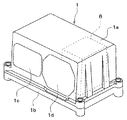
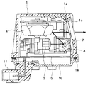
本発明の一実施形態を適用した距離検出装置の斜視図、断面図および上面図をそれぞれ図1〜図3に示す。以下、これらの図に基づいて距離検出装置の構造について説明する。
(First embodiment)
A perspective view, a sectional view, and a top view of a distance detecting device to which an embodiment of the present invention is applied are shown in FIGS. Hereinafter, the structure of the distance detection device will be described with reference to these drawings.
図1〜図3に示される距離検出装置は、車両に搭載されるもので、例えば、図2における紙面右方向が車両前方を向くように配置され、例えばオートクルーズ時に車両前方の先行車等の障害物と自車両との距離を検出するレーザレーダとして用いられる。 The distance detection device shown in FIGS. 1 to 3 is mounted on a vehicle, and is arranged, for example, such that the right direction in FIG. 2 faces the front of the vehicle. It is used as a laser radar that detects the distance between an obstacle and the host vehicle.
距離検出装置は、略立方体形状で構成された樹脂製のケース1内に各種部品が収容されて構成されている。
The distance detection device is configured by housing various components in a
ケース1は、第1ケース部1aと第2ケース部1bとによって構成されている。第1ケース部1aは、一面が開口する箱型を成しており、この第1ケース部1aによって構成される収容スペース内に、各種部品が収容されるようになっている。第1ケース部1aは、基本的には同じ材料の樹脂によって構成されているが、第1ケース部1aのうち車両前方に向けられる面において、左右に並べられて、例えばガラスやアクリル樹脂等の透光性部材によって構成された投射窓部1cと入射窓部1dが備えられた構成となっている。
The
第2ケース部1bは、例えば樹脂などによって構成され、第1ケース部1aの開口した面に、シール部材1eを介して組みつけられている。
The
なお、図3に示されるように、第2ケース部1bの一部には、ケース1から部分的に突出したコネクタ1fが配置されている。そして、このコネクタ1fを介して、ケース1内外の電気的接続が行えるようになっている。
As shown in FIG. 3, a connector 1f that partially protrudes from the
このように構成されるケース1内に、各種部品が収容されている。具体的には、ケース1における下方位置には、発光部2、反射ミラー3およびポリゴンミラー4が備えられていると共に、距離検出装置を制御するための制御部(図示せず)などが備えられえた回路基板5が備えられている。また、入射窓部1dと対向するように受光部6も配置されている。
Various parts are accommodated in the
発光部2は、回路基板5に備えられた制御部からの駆動信号に基づいて駆動されるもので、反射ミラー3に向けてレーザ光の照射を行うようになっている。例えば、この発光部2は、レーザダイオードによって構成され、パルス状の探査用電磁波となるレーザ光(探査光)を発生するようになっている。
The
反射ミラー3は、発光部2が発したレーザ光を反射し、ポリゴンミラー4に向けて照射するためのものである。この反射ミラー3は、ケース1の内壁に固定された支持部7により、ケース1に対して揺動可能に支持されている。そして、回路基板5に備えられた制御部によって駆動される図示しないモータに反射ミラー3が揺動されることで、紙面垂直方向を軸とした反射角度の微調整(例えば、1度程度の調整)が行われるようになっている。
The
ポリゴンミラー4は、六角錐の先端部分を切り取ったような六角錐台状の形状を成している。このポリゴンミラー4は、ケース1の下面側において、回路基板5上に六角錐軸を中心として回転可能なように支持されており、回路基板5に備えられた制御部によって駆動される図示しないモータによって回転駆動されるようになっている。このポリゴンミラー4は、その側面がすべて反射ミラーとして働くようになっており、スキャンミラーとして機能する。
The
具体的には、ポリゴンミラー4は、発光部2が発したレーザ光が反射ミラー3で反射されると、そのレーザ光をさらに反射させ、第1ケース部1aの投射窓部1cを通じてその反射光を車両前方に導くようになっている。そして、モータによってポリゴンミラー4が駆動されると、その回転に応じてポリゴンミラー4の側面の角度が変わることから、反射光の投射角が変わり、車両前方における所定の範囲がスキャンされるようになっている。
Specifically, when the laser light emitted from the
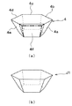
図4は、本実施形態におけるポリゴンミラー4と従来のポリゴンミラーJ1の模式図を示したものである。
FIG. 4 is a schematic diagram of the
図4(b)に示されるように、従来のポリゴンミラーJ1は、六角錐の先端部分を切り取った六角錐台で構成されている。すなわち、従来の六角錐台で構成されたポリゴンミラーJ1は、上下方向の必要スキャン範囲になるように、微小角度ずつ各面の角度をかえている。例えば、ポリゴンミラーJ1の任意の1面が六角錐台の底面に対して成す角度がθ1[deg]であったとすると、その面の隣の面はθ1−Δ1[deg]、さらに隣の面はθ1−2Δ1[deg]というように、任意の1面を基準として6面が、底面に対してθ1[deg]、 θ1−Δ1[deg]、 θ1−2Δ1[deg]、 θ1−3Δ1[deg]、 θ1−4Δ1[deg]、 θ1−5Δ1[deg]の角度とされている。 As shown in FIG. 4B, the conventional polygon mirror J1 is formed of a hexagonal frustum obtained by cutting off the tip of the hexagonal pyramid. In other words, the polygon mirror J1 configured with a conventional hexagonal frustum changes the angle of each surface by a minute angle so as to be in the required scanning range in the vertical direction. For example, if the angle formed by any one surface of the polygon mirror J1 with respect to the bottom surface of the hexagonal frustum is θ1 [deg], the next surface is θ1−Δ1 [deg], and the next surface is 6 planes with any one plane as a reference, such as θ1-2Δ1 [deg], θ1 [deg], θ1-Δ1 [deg], θ1-2Δ1 [deg], θ1-3Δ1 [deg] with respect to the bottom surface , Θ1-4Δ1 [deg], θ1-5Δ1 [deg].
これに対し、図4(a)に示されるように、本実施形態のポリゴンミラー4は、六角錐台で構成され、側面の1つの面が面取りされた形状となっている。すなわち、ポリゴンミラー4のうちの5つの面を第1の面4a〜4e、残る1つの面を第2の面4fとし、第1の面4a〜4eが六角錐台の底面に対して第1の所定範囲にレーザ光が到達する角度を成し、第2の面4fがその底面に対して第1の所定範囲よりも上方にある第2の所定範囲にレーザ光が到達する角度となるように設定されている。
On the other hand, as shown in FIG. 4A, the
換言すれば、ポリゴンミラー4の任意の1面4aが六角錐台の底面に対して成す角度がθ1’[deg]であったとすると、その面の隣の面4bはθ1’−Δ1’[deg]、さらに隣の面4cはθ1’−2Δ1’[deg]というように、任意の1面を基準として隣接する5面が順に、底面に対してθ1’[deg]、 θ1’ −Δ1’[deg]、 θ1’ −2Δ1’[deg]、 θ1’ −3Δ1’[deg]、 θ1’ −4Δ1’[deg]の角度とされている。そして、残る1面4fが、底面に対してθ1’[deg]よりも大きなφ1[deg]の角度とされている。
In other words, if the angle formed by any one
このため、ポリゴンミラー4にレーザ光が反射したときに、その反射光が投射窓部1cを通じて車両前方に出射されることになるが、第1の面4a〜4eで反射したときには通常の高さで出射され、第2の面4fで反射したときには通常の高さよりも高い位置に向かって出射されることになる。
For this reason, when the laser light is reflected on the
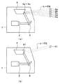
図5は、この様子を示した模式図である。図5(a)は、レーザ光がポリゴンミラー4における第1の面4a〜4eで反射したときの様子、図5(b)は、レーザ光がポリゴンミラー4における第2の面4fで反射したときの様子を示している。
FIG. 5 is a schematic diagram showing this state. FIG. 5A shows a state in which the laser light is reflected by the
これらの図に示されるように、レーザ光がポリゴンミラー4における第1の面4a〜4eで反射したときには、車両前方の通常の高さとなり、自車両から比較的遠距離を走行している先行車両までレーザ光が届くことから、近距離だけでなく遠距離も検出範囲となる。
As shown in these drawings, when the laser beam is reflected by the
これに対し、レーザ光がポリゴンミラー4における第2の面4fで反射したときには、車両前方の通常の高さよりも高い位置となり、自車両から比較的近距離を走行している先行車両にはレーザ光が照射されるが、先行車両との距離が離れるとレーザ光が車両の高さよりも高くなるから、近距離が検出範囲となる。
On the other hand, when the laser beam is reflected by the
このため、通常の距離測定はポリゴンミラー4における第1の面4a〜4eを用いて行われ、近距離測定は第2の面4fを用いて行われる。
For this reason, the normal distance measurement is performed using the
受光部6は、図3に示されるように、フレネルレンズ6aと例えばフォトダイオードによって構成される受光素子6bなどによって構成され、フレネルレンズ6aによってレーザ光を集光し、受光素子6bに集光されたレーザ光が照射されるとその受光強度に対応する出力電流もしくは出力電圧を発生するようになっている。この受光部6により、ケース1の上方に照射されたレーザ光を検出できるようになっている。そして、この受光部6の出力電流もしくは出力電圧は、回路基板5に備えられた制御部に入力されるようになっている。
As shown in FIG. 3, the
また、受光部6は、ポリゴンミラー4に対して横置き、すなわちポリゴンミラー4の回転軸と垂直方向にずらされて配置されている。
In addition, the
次に、本実施形態のように構成された距離検出装置の作動について説明する。 Next, the operation of the distance detection device configured as in the present embodiment will be described.
上記構成の距離検出装置は、例えば車室内に備えられたオートクルーズコントロールのスイッチが投入されると、前方車両との距離の検出を行う。 The distance detecting device having the above-described configuration detects the distance to the vehicle ahead when, for example, an auto cruise control switch provided in the passenger compartment is turned on.
まず、制御部からの駆動信号に基づいてモータが駆動され、反射ミラー3が所定の角度に調整される。そして、発光部2から所定のタイミングでレーザ光が照射され、そのレーザ光が反射ミラー3およびポリゴンミラー4で反射され、投射窓部1cから車両前方に照射される。このレーザ光が自車両の前方に位置する先行車両などによって反射すると、その反射光が入射窓部1dを通じてフレネルレンズ6aで集められ、受光素子6bに照射される。
First, the motor is driven based on the drive signal from the control unit, and the
これにより、受光素子6bは受けたレーザ光の強度に応じた出力電流もしくは出力電圧を発生させる。これが制御部によって検知され、制御部は、そのレーザ光を照射したタイミングとレーザ光が検出されたタイミングの時間差、つまり入力時間差とレーザ光の速度とから次式より先行車両との距離を検出する。
As a result, the
(数1)
レーザ光の速度×入力時間差/2
そして、ポリゴンミラー4が回転させられることにより、ポリゴンミラー4における第1の面4a〜4eおよび第2の面4fそれぞれにレーザ光が照射され、通常の高さとそれよりも高い位置にレーザ光を出射させることができるため、通常の高さとそれよりも高い位置双方をスキャンすることが可能となる。
(Equation 1)
Laser beam speed x input time difference / 2
Then, when the
なお、本実施形態では、ポリゴンミラー4が第1の面4a〜4eと第2の面4fとで角度が変えられているが、ポリゴンミラー4の側面におけるどの面が第2の面4fとされているかについては予め分かっている。このため、第1の面4a〜4eを用いて距離検出を行ったタイミングか、第2の面4fを用いて距離検出を行ったタイミングかを区別することにより、車高が普通の高さの車両の距離検出を行ったのか、もしくは、車高が高い車両の距離検出を行ったのかを確認しつつ、距離検出を行うことが可能となる。
In this embodiment, the angle of the
このようにして先行車両と自車両との距離が検出されると、その検出結果に応じた出力がコネクタ1fを介してケース1の外部、例えばエンジンECUやブレーキECUなどに出力される。これにより、先行車両と自車両との距離が所定距離に維持されるように、エンジン出力もしくは制動力が制御されるようになっている。
When the distance between the preceding vehicle and the host vehicle is detected in this manner, an output corresponding to the detection result is output to the outside of the
以上説明したように、本実施形態に示す距離検出装置では、レーザ光を第1の所定範囲に出射させる第1の面4a〜4eと、レーザ光を第2の所定範囲に出射させる第2の面4fとを有した形状としてポリゴンミラー4を構成するようにしている。
As described above, in the distance detection device shown in the present embodiment, the
このため、ポリゴンミラー4を回転させることにより、投射窓部1cを通じてレーザ光を第1の所定範囲と第2の所定範囲に出射させることができる。したがって、車両前方の通常の高さを照射することができるだけでなく、車両前方における通常の高さよりも上方位置を照射することもできるようになり、例えば車高が高い車等のように、障害物中の反射対象が高い位置にある場合においても、レーザ光をその反射対象に照射でき、正確な距離検出を行うことが可能となる。
For this reason, by rotating the
(第2実施形態)
本発明の第2実施形態について説明する。図6は、本実施形態における距離検出装置のポリゴンミラーの斜視図である。なお、本実施形態における距離検出装置は、第1実施形態に対してポリゴンミラー4の形状が異なるものであり、その他の部分については同様であるため、異なる部分についてのみ説明する。
(Second Embodiment)
A second embodiment of the present invention will be described. FIG. 6 is a perspective view of a polygon mirror of the distance detection device in the present embodiment. Note that the distance detection device in the present embodiment is different from the first embodiment in the shape of the
本実施形態の距離検出装置では、ポリゴンミラー4の形状は、六角錐台となっているが、六角錐台の側面のうちの3面を第1’の面4a’〜4c’、残る3面を第2’の面4d’〜4f’とすると、第1’の面4a’〜4c’は平面形状、第2’の面4d’〜4f’は凸平面形状となっている。
In the distance detection device of the present embodiment, the
換言すれば、ポリゴンミラー4の任意の1面4a’が六角錐台の底面に対して成す角度がθ2[deg]であったとすると、その面の隣の面4d’はθ2’[deg]、さらに隣の面4b’はθ2−Δ2[deg]、さらにその隣の面4e’はθ2’−Δ2’[deg]というように、任意の1面を基準として隣接する6面が順に、底面に対してθ2[deg]、 θ2’[deg]、 θ2−Δ2[deg]、θ2’−Δ2’[deg]、θ2−2Δ2[deg]、θ2’−2Δ2’[deg]の角度とされている。
In other words, if the angle formed by any one
このような構成によれば、第1’の面4a’〜4c’にレーザ光を照射したときに、その反射光の範囲は例えば上下方向に第1’の所定範囲(例えば4度程度)になるが、第2’の面4d’〜4f’にレーザ光を照射したときには、凸平面によってレーザ光の幅が拡大されるため、その反射光の範囲が上下方向に第1’の所定範囲よりも広い第2’の所定範囲(すなわち4度以上)となる。 According to such a configuration, when laser light is irradiated onto the first ′ surfaces 4a ′ to 4c ′, the range of the reflected light is, for example, a first predetermined range (for example, about 4 degrees) in the vertical direction. However, when the laser light is irradiated on the second ′ surfaces 4d ′ to 4f ′, the width of the laser light is expanded by the convex plane, so that the range of the reflected light is higher than the predetermined range of the first ′ in the vertical direction. Is also a wide 2 ′ predetermined range (that is, 4 degrees or more).
図7は、この様子を示した模式図である。図7(a)は、レーザ光がポリゴンミラー4における第1’の面4a’〜4c’で反射したときの様子、図7(b)は、レーザ光がポリゴンミラー4における第2’の面4d’〜4f’で反射したときの様子を示している。
FIG. 7 is a schematic view showing this state. 7A shows a state in which the laser light is reflected by the first ′ surfaces 4a ′ to 4c ′ of the
この図に示されるように、第2’の面4d’〜4f’を用いてレーザ光を照射したときには、車両前方の通常の高さだけでなくそれよりも高い位置を含めた範囲にレーザ光を照射することが可能となる。このため、通常の距離測定(遠距離測定)をポリゴンミラー4における第1’の面4a’〜4c’を用いて行い、近距離測定をポリゴンミラー4における第2’の面4d’〜4f’を用いて行うことができる。
As shown in this figure, when the laser beam is irradiated using the second ′ surfaces 4d ′ to 4f ′, the laser beam is included in a range including not only the normal height in front of the vehicle but also a higher position. Can be irradiated. For this reason, normal distance measurement (long distance measurement) is performed using the first '
このように、レーザ光を第1’の面4a’〜4c’によって反射したときの第1’の所定範囲よりも、第2’の面4d’〜4f’で反射したときの第2’の所定範囲の方が広くなるようにし、第2’の所定範囲内に通常の高さよりも高い位置が含まれるようにすることで、第1実施形態と同様の効果を得ることができる。 In this way, the second ′ of the laser beam reflected by the second ′ surfaces 4d ′ to 4f ′ is more than the predetermined range of the first ′ when the laser beams are reflected by the first ′ surfaces 4a ′ to 4c ′. By making the predetermined range wider and including a position higher than the normal height in the second 'predetermined range, the same effect as in the first embodiment can be obtained.
なお、本実施形態における第1’、第2’の所定範囲や第1’、第2’の面は、第1実施形態で示した第1、第2の所定範囲や第1、第2の面と必ずしも一致するとは限らないため、ここでは「’」を付して説明したが、これらも第1実施形態と同様、本発明でいう第1、第2の所定範囲や第1、第2の面に相当するものである。 The first 'and second' predetermined ranges and the first 'and second' surfaces in the present embodiment are the first and second predetermined ranges and the first and second ranges shown in the first embodiment. Since it does not always coincide with the surface, “′” is used here for explanation, but these are also the first and second predetermined ranges and the first and second in the present invention as in the first embodiment. This is equivalent to
(他の実施形態)
(1)上記第1、第2実施形態では、探査光として、光波の1つであるレーザ光を用いる場合について説明したが、どのような光波を用いても良く、必ずしもレーザ光である必要は無い。
(Other embodiments)
(1) In the first and second embodiments described above, the case where laser light, which is one of light waves, is used as the exploration light. However, any light wave may be used, and the laser light is not necessarily required. No.
(2)上記第1、第2実施形態では、ポリゴンミラー4における側面が下方に向けられる場合を示したが、上方に向けられるような形態に対しても本発明を適用することができる。この場合、通常の距離測定に用いられる第1の面4a〜4eと近距離測定に用いられる第2の面4fとが平面で構成されるのであれば、六角錐台とされたポリゴンミラー4の底面に対して第1の面4a〜4eが成す角度に比べ、第2の面4fがその底面に対して成す角度の方が小さくなるように、すなわち第2の面4fの方が第1の面4a〜4eよりも上方を向くようにすれば良い。
(2) In the first and second embodiments, the case where the side surface of the
また、近距離測定に用いられる第2’の面4d’〜4f’が凸平面形状とされるものに対しては、第2’の面4d’〜4f’で反射したレーザ光の範囲が通常の高さよりも高い位置を含むようにすれば良い。 In addition, for the case where the second ′ surfaces 4d ′ to 4f ′ used for the short distance measurement have a convex planar shape, the range of the laser light reflected by the second ′ surfaces 4d ′ to 4f ′ is usually A position higher than the height may be included.
(3)上記第1、第2実施形態では、回転体として六角錐台のポリゴンミラー4を例に挙げて説明したが、回転体は必ずしも六角錐台である必要はない。すなわち、回転体は、上述した通常の距離検出に用いる第1の面4a〜4eまたは4a’〜4c’と、通常よりも高い位置までレーザ光が照射されるようにする近距離検出に用いられる第2の面4fあるいは第2’の面4d’〜4f’とを有した構成となっていれば、どのような形状であっても構わない。例えば、回転体が六角錐台ではない他の多角形錐形状で構成されていても良い。
(3) In the first and second embodiments described above, the hexagonal
(4)上記第1、第2実施形態で示した第1の面4a〜4eまたは第1’の面4a’〜4c’と第2の面4fまたは第2’の面4d’〜4f’の数については、単なる例示であり、少なくとも第1の面4a〜4eまたは第1’の面4a’〜4c’と第2の面4fまたは第2’の面4d’〜4f’がそれぞれ1つ以上含まれていればよい。
(4) The first surfaces 4a to 4e or the first '
1…ケース、1a…第1ケース部、1b…第2ケース部、1c…投射窓部、
1d…入射窓部、2…発光部、3…反射ミラー、4…ポリゴンミラー、
4a〜4e…第1実施形態における第1の面、
4b〜4f…第1実施形態における第2の面、
4a’〜4c’…第2実施形態における第1’の面
4d’〜4f’…第2実施形態における第2’の面
5…回路基板、6…受光部、7…支持部。
DESCRIPTION OF
1d: entrance window part, 2 ... light emitting part, 3 ... reflection mirror, 4 ... polygon mirror,
4a to 4e: the first surface in the first embodiment,
4b to 4f ... the second surface in the first embodiment,
4a 'to 4c' ... 1 'surface in the
Claims (6)
前記ケース内に配置され、探査光を照射する発光部(2)と、
前記ケース内に配置され、反射面を有し、その反射面にて前記探査光を反射することで、前記探査光を所定の範囲で走査するスキャン用の回転体(4)と、
前記回転体によって反射された前記探査光を通過させる透光性材料で構成された投射窓部(1c)と、
前記ケース内に配置され、前記探査光の反射光を受け取る受光部(6)とを備え、
前記発光部が照射した前記探査光を前記回転体で反射させ、前記投射窓部を通じて前記ケースの外部に向けて照射したのち、前記ケースの外部で反射してきた前記探査光を前記受光部で受け取り、それに基づいて前記探査光が反射させられた障害物までの距離を検出する距離検出装置において、
前記回転体は、前記反射面として、前記探査光を前記投射窓部から第1の所定範囲に出射させる第1の面(4a〜4e)と、前記探査光が前記第1の面で反射させたときよりも高い位置に照射されるように、前記探査光を前記投射窓部から第2の所定範囲に出射させる第2の面(4f)とを有した構成となっており、該回転体が回転することにより、前記探査光が前記投射窓部を通じて前記第1の所定範囲と前記第2の所定範囲に出射されるようになっていることを特徴とする距離検出装置。 Case (1, 1a, 1b);
A light emitting unit (2) disposed in the case and irradiating the search light;
A scanning rotator (4) disposed in the case, having a reflecting surface, and scanning the exploration light within a predetermined range by reflecting the exploration light on the reflecting surface;
A projection window (1c) made of a translucent material that allows the exploration light reflected by the rotating body to pass through;
A light receiving portion (6) disposed in the case and receiving reflected light of the exploration light,
The exploration light emitted from the light emitting unit is reflected by the rotating body, irradiated to the outside of the case through the projection window, and then received by the light receiving unit. In the distance detection device for detecting the distance to the obstacle reflected by the exploration light based on it,
The rotating body has, as the reflection surface, a first surface (4a to 4e) that emits the exploration light from the projection window to a first predetermined range, and the exploration light is reflected by the first surface. And a second surface (4f) for emitting the exploration light from the projection window portion to a second predetermined range so that the position is higher than that of The distance detecting device is characterized in that the search light is emitted to the first predetermined range and the second predetermined range through the projection window by rotating.
前記ケース内に配置され、探査光を照射する発光部(2)と、
前記ケース内に配置され、反射面を有し、その反射面にて前記探査光を反射することで、前記探査光を所定の範囲で走査するスキャン用の回転体(4)と、
前記回転体によって反射された前記探査光を通過させる透光性材料で構成された投射窓部(1c)と、
前記ケース内に配置され、前記探査光の反射光を受け取る受光部(6)とを備え、
前記発光部が照射した前記探査光を前記回転体で反射させ、前記投射窓部を通じて前記ケースの外部に向けて照射したのち、前記ケースの外部で反射してきた前記探査光を前記受光部で受け取り、それに基づいて前記探査光が反射させられた障害物までの距離を検出する距離検出装置において、
前記回転体は、前記反射面として、前記探査光を前記投射窓部から上下方向の幅が第1の所定範囲となるように出射させる第1の面(4a’〜4c’)と、前記探査光を前記投射窓部から前記第1の所定範囲よりも広くかつ前記第1の面で反射させたときよりも高い位置を含めた第2の所定範囲となるように出射させる第2の面(4d’〜4f’)とを有した構成となっており、該回転体が回転することにより、前記探査光が前記投射窓部を通じて前記第1の所定範囲と前記第2の所定範囲で出射されるようになっていることを特徴とする距離検出装置。 Case (1, 1a, 1b);
A light emitting unit (2) disposed in the case and irradiating the search light;
A scanning rotator (4) disposed in the case, having a reflecting surface, and scanning the exploration light within a predetermined range by reflecting the exploration light on the reflecting surface;
A projection window (1c) made of a translucent material that allows the exploration light reflected by the rotating body to pass through;
A light receiving portion (6) disposed in the case and receiving reflected light of the exploration light,
The exploration light emitted from the light emitting unit is reflected by the rotating body, irradiated to the outside of the case through the projection window, and then received by the light receiving unit. In the distance detection device for detecting the distance to the obstacle reflected by the exploration light based on it,
The rotating body has, as the reflection surface, a first surface (4a ′ to 4c ′) that emits the exploration light from the projection window so that a vertical width is within a first predetermined range, and the exploration A second surface that emits light from the projection window so as to be in a second predetermined range that is wider than the first predetermined range and includes a position higher than when reflected by the first surface ( 4d ′ to 4f ′), and when the rotating body rotates, the exploration light is emitted through the projection window in the first predetermined range and the second predetermined range. A distance detecting device characterized by being configured to be configured as described above.
Priority Applications (4)
| Application Number | Priority Date | Filing Date | Title |
|---|---|---|---|
| JP2004104119A JP2005291787A (en) | 2004-03-31 | 2004-03-31 | Distance detection device |
| DE102005014466A DE102005014466A1 (en) | 2004-03-31 | 2005-03-30 | Object detector for a vehicle |
| CNB2005100639035A CN100425945C (en) | 2004-03-31 | 2005-03-30 | Object detector of vehicle |
| US11/093,841 US7382442B2 (en) | 2004-03-31 | 2005-03-30 | Object detector of vehicle |
Applications Claiming Priority (1)
| Application Number | Priority Date | Filing Date | Title |
|---|---|---|---|
| JP2004104119A JP2005291787A (en) | 2004-03-31 | 2004-03-31 | Distance detection device |
Publications (1)
| Publication Number | Publication Date |
|---|---|
| JP2005291787A true JP2005291787A (en) | 2005-10-20 |
Family
ID=35034286
Family Applications (1)
| Application Number | Title | Priority Date | Filing Date |
|---|---|---|---|
| JP2004104119A Pending JP2005291787A (en) | 2004-03-31 | 2004-03-31 | Distance detection device |
Country Status (4)
| Country | Link |
|---|---|
| US (1) | US7382442B2 (en) |
| JP (1) | JP2005291787A (en) |
| CN (1) | CN100425945C (en) |
| DE (1) | DE102005014466A1 (en) |
Cited By (11)
| Publication number | Priority date | Publication date | Assignee | Title |
|---|---|---|---|---|
| JP2010066101A (en) * | 2008-09-10 | 2010-03-25 | Ihi Corp | Laser radar and method of watching boundary by the same |
| JP2014071027A (en) * | 2012-09-28 | 2014-04-21 | Denso Wave Inc | Laser radar device |
| JP2015007578A (en) * | 2013-06-25 | 2015-01-15 | 株式会社デンソー | Optical scanning device |
| KR101504563B1 (en) * | 2014-04-23 | 2015-03-20 | 삼인정보시스템(주) | Indicator for laser scanning and method for measuring coordinate of target using the indicator |
| US8988664B2 (en) | 2012-02-22 | 2015-03-24 | Ricoh Company, Ltd. | Distance measuring device |
| WO2015122095A1 (en) * | 2014-02-13 | 2015-08-20 | コニカミノルタ株式会社 | Mirror unit, distance measuring device, and laser radar, and mobile body and fixed object having these |
| JP2017015404A (en) * | 2015-06-26 | 2017-01-19 | 株式会社デンソー | Optical scanner and on-vehicle system |
| JP2017090135A (en) * | 2015-11-06 | 2017-05-25 | アイシン精機株式会社 | Distance measuring device |
| JP2018059847A (en) * | 2016-10-06 | 2018-04-12 | オムロンオートモーティブエレクトロニクス株式会社 | Laser radar equipment |
| KR20210025777A (en) * | 2019-08-28 | 2021-03-10 | (주)카네비컴 | Lidar device and operation method thereof |
| JP2022510039A (en) * | 2019-01-04 | 2022-01-25 | ブラックモア センサーズ アンド アナリティクス エルエルシー | LIDAR system including multi-facet deflector |
Families Citing this family (62)
| Publication number | Priority date | Publication date | Assignee | Title |
|---|---|---|---|---|
| CN100392428C (en) * | 2006-01-10 | 2008-06-04 | 武汉理工大学 | A visible laser detector |
| AT508562B1 (en) * | 2009-09-02 | 2011-02-15 | Riegl Laser Measurement Sys | 3-D MEASUREMENT DEVICE |
| DE102009040325A1 (en) * | 2009-09-05 | 2011-03-17 | Conti Temic Microelectronic Gmbh | Sensor system for detecting environmental objects |
| DE102013205589A1 (en) * | 2013-03-28 | 2014-10-02 | Hilti Aktiengesellschaft | Device for the optical measurement of a distance to a reflecting or scattering target object |
| US9239959B1 (en) | 2013-04-08 | 2016-01-19 | Lockheed Martin Corporation | Multi-resolution, wide field-of-view, unmanned ground vehicle navigation sensor |
| TWI552910B (en) * | 2013-05-23 | 2016-10-11 | 鴻海精密工業股份有限公司 | Vehicle |
| KR102656372B1 (en) | 2016-12-30 | 2024-04-12 | 세욘드, 인크. | Multiwavelength lidar design |
| US10942257B2 (en) | 2016-12-31 | 2021-03-09 | Innovusion Ireland Limited | 2D scanning high precision LiDAR using combination of rotating concave mirror and beam steering devices |
| WO2018129408A1 (en) | 2017-01-05 | 2018-07-12 | Innovusion Ireland Limited | Method and system for encoding and decoding lidar |
| CN106842228B (en) * | 2017-01-19 | 2023-08-29 | 北京飞思迈尔光电科技有限公司 | Optical scanning sensor |
| US10338198B2 (en) * | 2017-04-03 | 2019-07-02 | Ford Global Technologies, Llc | Sensor apparatus |
| DE112018002081T5 (en) * | 2017-04-19 | 2020-07-02 | Beijing Surestar Technology Co., Ltd | Laser scanning device, laser radar set and scanning method of the laser radar set |
| CN109870708B (en) * | 2017-12-05 | 2024-09-13 | 北科天绘(合肥)激光技术有限公司 | Intelligent vehicle with laser radar device |
| JP6967444B2 (en) * | 2017-12-22 | 2021-11-17 | パナソニック株式会社 | Mobile vehicle |
| US11493601B2 (en) | 2017-12-22 | 2022-11-08 | Innovusion, Inc. | High density LIDAR scanning |
| WO2019135494A1 (en) * | 2018-01-08 | 2019-07-11 | 주식회사 에스오에스랩 | Lidar device |
| US10591598B2 (en) * | 2018-01-08 | 2020-03-17 | SOS Lab co., Ltd | Lidar device |
| US11977184B2 (en) | 2018-01-09 | 2024-05-07 | Seyond, Inc. | LiDAR detection systems and methods that use multi-plane mirrors |
| US11675050B2 (en) | 2018-01-09 | 2023-06-13 | Innovusion, Inc. | LiDAR detection systems and methods |
| WO2019165130A1 (en) | 2018-02-21 | 2019-08-29 | Innovusion Ireland Limited | Lidar detection systems and methods with high repetition rate to observe far objects |
| US11927696B2 (en) | 2018-02-21 | 2024-03-12 | Innovusion, Inc. | LiDAR systems with fiber optic coupling |
| WO2020013890A2 (en) | 2018-02-23 | 2020-01-16 | Innovusion Ireland Limited | Multi-wavelength pulse steering in lidar systems |
| WO2019165095A1 (en) | 2018-02-23 | 2019-08-29 | Innovusion Ireland Limited | Distributed lidar systems |
| US11988773B2 (en) | 2018-02-23 | 2024-05-21 | Innovusion, Inc. | 2-dimensional steering system for lidar systems |
| US11567182B2 (en) | 2018-03-09 | 2023-01-31 | Innovusion, Inc. | LiDAR safety systems and methods |
| US11789132B2 (en) | 2018-04-09 | 2023-10-17 | Innovusion, Inc. | Compensation circuitry for lidar receiver systems and method of use thereof |
| WO2019199775A1 (en) | 2018-04-09 | 2019-10-17 | Innovusion Ireland Limited | Lidar systems and methods for exercising precise control of a fiber laser |
| KR102050678B1 (en) | 2018-05-14 | 2019-12-03 | 주식회사 에스오에스랩 | Lidar device |
| US11675053B2 (en) | 2018-06-15 | 2023-06-13 | Innovusion, Inc. | LiDAR systems and methods for focusing on ranges of interest |
| US11579300B1 (en) | 2018-08-21 | 2023-02-14 | Innovusion, Inc. | Dual lens receive path for LiDAR system |
| US11614526B1 (en) | 2018-08-24 | 2023-03-28 | Innovusion, Inc. | Virtual windows for LIDAR safety systems and methods |
| US11579258B1 (en) | 2018-08-30 | 2023-02-14 | Innovusion, Inc. | Solid state pulse steering in lidar systems |
| US12313788B1 (en) | 2018-10-09 | 2025-05-27 | Seyond, Inc. | Ultrashort pulses in LiDAR systems |
| CN114114606B (en) | 2018-11-14 | 2024-09-06 | 图达通智能美国有限公司 | LIDAR systems and methods using polygonal mirrors |
| US11391822B2 (en) * | 2018-11-30 | 2022-07-19 | Seagate Technology Llc | Rotating pyramidal mirror |
| KR102577234B1 (en) * | 2019-01-04 | 2023-09-08 | 블랙모어 센서스 앤드 애널리틱스, 엘엘씨 | LIDAR device with rotating polygon deflector with refractive facets |
| US11822010B2 (en) | 2019-01-04 | 2023-11-21 | Blackmore Sensors & Analytics, Llc | LIDAR system |
| WO2020146493A1 (en) | 2019-01-10 | 2020-07-16 | Innovusion Ireland Limited | Lidar systems and methods with beam steering and wide angle signal detection |
| US11486970B1 (en) | 2019-02-11 | 2022-11-01 | Innovusion, Inc. | Multiple beam generation from a single source beam for use with a LiDAR system |
| CN109709529B (en) * | 2019-03-05 | 2024-12-27 | 深圳市镭神智能系统有限公司 | A rotating prism and multi-line laser radar ranging system |
| CN109870707B (en) * | 2019-03-07 | 2020-04-21 | 南京理工大学 | Pyramid-shaped laser synchronous scanning imaging device for underwater vehicle |
| US11977185B1 (en) | 2019-04-04 | 2024-05-07 | Seyond, Inc. | Variable angle polygon for use with a LiDAR system |
| KR102281886B1 (en) | 2019-09-05 | 2021-07-26 | 주식회사 에스오에스랩 | A lidar device |
| US11619828B2 (en) * | 2020-01-17 | 2023-04-04 | Stmicroelectronics (Research & Development) Limited | Transmission beam splitter |
| JP7452044B2 (en) * | 2020-01-31 | 2024-03-19 | 株式会社デンソー | light detection device |
| KR20220136336A (en) | 2020-02-10 | 2022-10-07 | 헤사이 테크놀로지 씨오., 엘티디. | Adaptive emitters and receivers for lidar systems |
| CN113906310B (en) * | 2020-05-07 | 2025-10-28 | 深圳市速腾聚创科技有限公司 | LiDAR and autonomous driving equipment |
| CN111798698B (en) * | 2020-06-24 | 2022-04-08 | 中国第一汽车股份有限公司 | Method and device for determining front target vehicle and vehicle |
| US12061289B2 (en) | 2021-02-16 | 2024-08-13 | Innovusion, Inc. | Attaching a glass mirror to a rotating metal motor frame |
| US11789128B2 (en) | 2021-03-01 | 2023-10-17 | Innovusion, Inc. | Fiber-based transmitter and receiver channels of light detection and ranging systems |
| US11555895B2 (en) | 2021-04-20 | 2023-01-17 | Innovusion, Inc. | Dynamic compensation to polygon and motor tolerance using galvo control profile |
| US11614521B2 (en) | 2021-04-21 | 2023-03-28 | Innovusion, Inc. | LiDAR scanner with pivot prism and mirror |
| CN117178199A (en) * | 2021-04-22 | 2023-12-05 | 图达通智能美国有限公司 | Compact light detection and ranging design with high resolution and ultra-wide field of view |
| WO2022225859A1 (en) | 2021-04-22 | 2022-10-27 | Innovusion, Inc. | A compact lidar design with high resolution and ultra-wide field of view |
| US11768294B2 (en) | 2021-07-09 | 2023-09-26 | Innovusion, Inc. | Compact lidar systems for vehicle contour fitting |
| US20230049679A1 (en) * | 2021-08-04 | 2023-02-16 | Beijing Voyager Technology Co., Ltd. | Flash light detection and ranging system having adjustable field of view |
| CN113721256A (en) * | 2021-09-24 | 2021-11-30 | 探维科技(北京)有限公司 | Angle splicing laser radar system |
| US12468017B2 (en) | 2021-10-15 | 2025-11-11 | Seyond, Inc. | Integrated mirror motor galvanometer |
| CN216356147U (en) | 2021-11-24 | 2022-04-19 | 图达通智能科技(苏州)有限公司 | Vehicle-mounted laser radar motor, vehicle-mounted laser radar and vehicle |
| CN114365014A (en) * | 2021-12-13 | 2022-04-15 | 深圳市镭神智能系统有限公司 | Laser scanning module, laser radar, vehicle and robot |
| US12204033B2 (en) | 2022-03-25 | 2025-01-21 | Seyond, Inc. | Multimodal detection with integrated sensors |
| US11871130B2 (en) | 2022-03-25 | 2024-01-09 | Innovusion, Inc. | Compact perception device |
Family Cites Families (5)
| Publication number | Priority date | Publication date | Assignee | Title |
|---|---|---|---|---|
| US5546188A (en) * | 1992-11-23 | 1996-08-13 | Schwartz Electro-Optics, Inc. | Intelligent vehicle highway system sensor and method |
| JPH1010233A (en) * | 1996-06-24 | 1998-01-16 | Mitsui Eng & Shipbuild Co Ltd | Laser type obstacle detection method and sensor |
| JP3475672B2 (en) | 1996-09-06 | 2003-12-08 | オムロン株式会社 | Optical module, laser radar device using the optical module, vehicle, photoelectric sensor |
| JP2000147124A (en) * | 1998-11-12 | 2000-05-26 | Denso Corp | On-vehicle radar device |
| JP2002031685A (en) * | 2000-07-17 | 2002-01-31 | Denso Corp | Reflection measuring device |
-
2004
- 2004-03-31 JP JP2004104119A patent/JP2005291787A/en active Pending
-
2005
- 2005-03-30 DE DE102005014466A patent/DE102005014466A1/en not_active Withdrawn
- 2005-03-30 CN CNB2005100639035A patent/CN100425945C/en not_active Expired - Fee Related
- 2005-03-30 US US11/093,841 patent/US7382442B2/en not_active Expired - Fee Related
Cited By (14)
| Publication number | Priority date | Publication date | Assignee | Title |
|---|---|---|---|---|
| JP2010066101A (en) * | 2008-09-10 | 2010-03-25 | Ihi Corp | Laser radar and method of watching boundary by the same |
| US8988664B2 (en) | 2012-02-22 | 2015-03-24 | Ricoh Company, Ltd. | Distance measuring device |
| JP2014071027A (en) * | 2012-09-28 | 2014-04-21 | Denso Wave Inc | Laser radar device |
| JP2015007578A (en) * | 2013-06-25 | 2015-01-15 | 株式会社デンソー | Optical scanning device |
| US10288723B2 (en) | 2014-02-13 | 2019-05-14 | Konica Minolta, Inc. | Mirror unit, distance measurement device and laser radar, and mobile body and fixed object having the mirror unit and the distance measurement device or the laser radar |
| WO2015122095A1 (en) * | 2014-02-13 | 2015-08-20 | コニカミノルタ株式会社 | Mirror unit, distance measuring device, and laser radar, and mobile body and fixed object having these |
| JPWO2015122095A1 (en) * | 2014-02-13 | 2017-03-30 | コニカミノルタ株式会社 | MIRROR UNIT, RANGING DEVICE, LASER RADAR, AND MOBILE AND FIXED OBJECT HAVING THEM |
| KR101504563B1 (en) * | 2014-04-23 | 2015-03-20 | 삼인정보시스템(주) | Indicator for laser scanning and method for measuring coordinate of target using the indicator |
| JP2017015404A (en) * | 2015-06-26 | 2017-01-19 | 株式会社デンソー | Optical scanner and on-vehicle system |
| JP2017090135A (en) * | 2015-11-06 | 2017-05-25 | アイシン精機株式会社 | Distance measuring device |
| JP2018059847A (en) * | 2016-10-06 | 2018-04-12 | オムロンオートモーティブエレクトロニクス株式会社 | Laser radar equipment |
| JP2022510039A (en) * | 2019-01-04 | 2022-01-25 | ブラックモア センサーズ アンド アナリティクス エルエルシー | LIDAR system including multi-facet deflector |
| KR20210025777A (en) * | 2019-08-28 | 2021-03-10 | (주)카네비컴 | Lidar device and operation method thereof |
| KR102284337B1 (en) * | 2019-08-28 | 2021-08-02 | (주)카네비컴 | Lidar device and operation method thereof |
Also Published As
| Publication number | Publication date |
|---|---|
| CN100425945C (en) | 2008-10-15 |
| US20050219504A1 (en) | 2005-10-06 |
| CN1677050A (en) | 2005-10-05 |
| DE102005014466A1 (en) | 2005-10-20 |
| US7382442B2 (en) | 2008-06-03 |
Similar Documents
| Publication | Publication Date | Title |
|---|---|---|
| JP2005291787A (en) | Distance detection device | |
| KR101665938B1 (en) | Optical system of multi lidar scanner using mirror rotation | |
| US11194020B2 (en) | Lidar-integrated lamp device for vehicle | |
| JP5402772B2 (en) | Optical radar device | |
| JP2005121638A (en) | Optoelectronic detection apparatus | |
| JP2009103482A (en) | Vehicle-mounted radar device | |
| JP4158725B2 (en) | Distance detector | |
| JP2005257324A (en) | Distance detector | |
| JP4193724B2 (en) | Distance detector | |
| JP2005233777A (en) | Distance detector | |
| JP2005233774A (en) | Distance detector | |
| JP2010064642A (en) | Lighting system for moving body | |
| JP4305231B2 (en) | Distance detector | |
| JP5747700B2 (en) | Laser radar system and mounting method | |
| JPH11326498A (en) | Optical radar device for vehicles | |
| JP2005227220A (en) | Distance detector | |
| JP2005257323A (en) | Distance detector | |
| JPWO2018143093A1 (en) | Measuring device | |
| JP4341435B2 (en) | Distance detector | |
| JP2017125765A (en) | Object detection device | |
| JP2005233773A (en) | Distance detector | |
| JP2005291789A (en) | Distance detecting apparatus | |
| JP6569328B2 (en) | Optical scanning device and in-vehicle system | |
| JP2005233775A (en) | Distance detector | |
| JP2007101404A (en) | Projecting and receiving device and ranging device |
Legal Events
| Date | Code | Title | Description |
|---|---|---|---|
| A621 | Written request for application examination |
Free format text: JAPANESE INTERMEDIATE CODE: A621 Effective date: 20060619 |
|
| A977 | Report on retrieval |
Free format text: JAPANESE INTERMEDIATE CODE: A971007 Effective date: 20090212 |
|
| A131 | Notification of reasons for refusal |
Free format text: JAPANESE INTERMEDIATE CODE: A131 Effective date: 20090217 |
|
| A02 | Decision of refusal |
Free format text: JAPANESE INTERMEDIATE CODE: A02 Effective date: 20090616 |