EP2292911B1 - Control system for internal combustion engine - Google Patents
Control system for internal combustion engine Download PDFInfo
- Publication number
- EP2292911B1 EP2292911B1 EP10168330A EP10168330A EP2292911B1 EP 2292911 B1 EP2292911 B1 EP 2292911B1 EP 10168330 A EP10168330 A EP 10168330A EP 10168330 A EP10168330 A EP 10168330A EP 2292911 B1 EP2292911 B1 EP 2292911B1
- Authority
- EP
- European Patent Office
- Prior art keywords
- control
- vehicle
- engine
- output
- control means
- Prior art date
- Legal status (The legal status is an assumption and is not a legal conclusion. Google has not performed a legal analysis and makes no representation as to the accuracy of the status listed.)
- Ceased
Links
- 238000002485 combustion reaction Methods 0.000 title claims description 17
- 230000005540 biological transmission Effects 0.000 claims description 45
- 230000000087 stabilizing effect Effects 0.000 claims description 44
- 230000007246 mechanism Effects 0.000 claims description 19
- 238000000034 method Methods 0.000 claims description 12
- 230000003247 decreasing effect Effects 0.000 claims description 8
- KEQFTVQCIQJIQW-UHFFFAOYSA-N N-Phenyl-2-naphthylamine Chemical compound C=1C=C2C=CC=CC2=CC=1NC1=CC=CC=C1 KEQFTVQCIQJIQW-UHFFFAOYSA-N 0.000 description 7
- 230000007423 decrease Effects 0.000 description 6
- 239000000446 fuel Substances 0.000 description 6
- 238000002347 injection Methods 0.000 description 6
- 239000007924 injection Substances 0.000 description 6
- 230000008569 process Effects 0.000 description 5
- 238000001514 detection method Methods 0.000 description 4
- 230000009977 dual effect Effects 0.000 description 4
- 230000000994 depressogenic effect Effects 0.000 description 3
- 230000001133 acceleration Effects 0.000 description 2
- 230000008859 change Effects 0.000 description 2
- 238000005192 partition Methods 0.000 description 2
- 101150101057 PBA1 gene Proteins 0.000 description 1
- 101100520663 Saccharomyces cerevisiae (strain ATCC 204508 / S288c) ADD66 gene Proteins 0.000 description 1
- 230000006399 behavior Effects 0.000 description 1
- 230000000881 depressing effect Effects 0.000 description 1
- 230000006870 function Effects 0.000 description 1
- 238000012986 modification Methods 0.000 description 1
- 230000004048 modification Effects 0.000 description 1
- 238000007493 shaping process Methods 0.000 description 1
- 230000006641 stabilisation Effects 0.000 description 1
- 238000011105 stabilization Methods 0.000 description 1
Images


Classifications
-
- F—MECHANICAL ENGINEERING; LIGHTING; HEATING; WEAPONS; BLASTING
- F02—COMBUSTION ENGINES; HOT-GAS OR COMBUSTION-PRODUCT ENGINE PLANTS
- F02D—CONTROLLING COMBUSTION ENGINES
- F02D9/00—Controlling engines by throttling air or fuel-and-air induction conduits or exhaust conduits
- F02D9/02—Controlling engines by throttling air or fuel-and-air induction conduits or exhaust conduits concerning induction conduits
-
- B—PERFORMING OPERATIONS; TRANSPORTING
- B60—VEHICLES IN GENERAL
- B60T—VEHICLE BRAKE CONTROL SYSTEMS OR PARTS THEREOF; BRAKE CONTROL SYSTEMS OR PARTS THEREOF, IN GENERAL; ARRANGEMENT OF BRAKING ELEMENTS ON VEHICLES IN GENERAL; PORTABLE DEVICES FOR PREVENTING UNWANTED MOVEMENT OF VEHICLES; VEHICLE MODIFICATIONS TO FACILITATE COOLING OF BRAKES
- B60T13/00—Transmitting braking action from initiating means to ultimate brake actuator with power assistance or drive; Brake systems incorporating such transmitting means, e.g. air-pressure brake systems
- B60T13/10—Transmitting braking action from initiating means to ultimate brake actuator with power assistance or drive; Brake systems incorporating such transmitting means, e.g. air-pressure brake systems with fluid assistance, drive, or release
- B60T13/24—Transmitting braking action from initiating means to ultimate brake actuator with power assistance or drive; Brake systems incorporating such transmitting means, e.g. air-pressure brake systems with fluid assistance, drive, or release the fluid being gaseous
- B60T13/46—Vacuum systems
- B60T13/52—Vacuum systems indirect, i.e. vacuum booster units
-
- B—PERFORMING OPERATIONS; TRANSPORTING
- B60—VEHICLES IN GENERAL
- B60T—VEHICLE BRAKE CONTROL SYSTEMS OR PARTS THEREOF; BRAKE CONTROL SYSTEMS OR PARTS THEREOF, IN GENERAL; ARRANGEMENT OF BRAKING ELEMENTS ON VEHICLES IN GENERAL; PORTABLE DEVICES FOR PREVENTING UNWANTED MOVEMENT OF VEHICLES; VEHICLE MODIFICATIONS TO FACILITATE COOLING OF BRAKES
- B60T17/00—Component parts, details, or accessories of power brake systems not covered by groups B60T8/00, B60T13/00 or B60T15/00, or presenting other characteristic features
- B60T17/02—Arrangements of pumps or compressors, or control devices therefor
-
- F—MECHANICAL ENGINEERING; LIGHTING; HEATING; WEAPONS; BLASTING
- F02—COMBUSTION ENGINES; HOT-GAS OR COMBUSTION-PRODUCT ENGINE PLANTS
- F02D—CONTROLLING COMBUSTION ENGINES
- F02D11/00—Arrangements for, or adaptations to, non-automatic engine control initiation means, e.g. operator initiated
- F02D11/06—Arrangements for, or adaptations to, non-automatic engine control initiation means, e.g. operator initiated characterised by non-mechanical control linkages, e.g. fluid control linkages or by control linkages with power drive or assistance
- F02D11/10—Arrangements for, or adaptations to, non-automatic engine control initiation means, e.g. operator initiated characterised by non-mechanical control linkages, e.g. fluid control linkages or by control linkages with power drive or assistance of the electric type
-
- F—MECHANICAL ENGINEERING; LIGHTING; HEATING; WEAPONS; BLASTING
- F02—COMBUSTION ENGINES; HOT-GAS OR COMBUSTION-PRODUCT ENGINE PLANTS
- F02D—CONTROLLING COMBUSTION ENGINES
- F02D9/00—Controlling engines by throttling air or fuel-and-air induction conduits or exhaust conduits
- F02D9/08—Throttle valves specially adapted therefor; Arrangements of such valves in conduits
- F02D9/10—Throttle valves specially adapted therefor; Arrangements of such valves in conduits having pivotally-mounted flaps
- F02D9/109—Throttle valves specially adapted therefor; Arrangements of such valves in conduits having pivotally-mounted flaps having two or more flaps
Definitions
- the present invention relates to a control system for an internal combustion engine, and particularly to a control system for an internal combustion engine which has a plurality of cylinders consisting of two or more cylinder groups, and a plurality of intake systems respectively corresponding to the cylinder groups.
- the brake booster for assisting the driver in operating the brake pedal of the automobile is widely used.
- the brake booster uses a negative pressure (a pressure which is lower than the atmospheric pressure) generated in the intake system of the internal combustion engine, to generate the assisting force.
- Japanese Patent Laid-open No. 2000-120474 JP-'474 discloses a control system for an internal combustion engine which has two cylinder groups and two intake systems corresponding to the two cylinder groups. The engine and the brake booster shown in JP-'474 are configured so that the negative pressure is supplied from the two intake systems to the brake booster.
- This control system is proposed contemplating a tendency that the negative pressure in the brake booster becomes insufficient when performing the lean-burn operation of the engine.
- the partition valve provided in the passage connecting the two intake systems is opened when the negative pressure in the brake booster is sufficient.
- the partition valve is closed and the throttle valve in the first intake system is controlled to be slightly closed while the throttle valve in the second intake system is controlled to an opening which is suitable for the lean-burn operation. Consequently, the negative pressure is secured by the first intake system.
- an output of the engine for driving the vehicle may sometimes be increased for securing running stability of the vehicle.
- the throttle valve is normally fully-closed to secure a sufficient negative pressure.
- the engine output is increased upon deceleration of the vehicle as described above, the negative pressure may become insufficient.
- the blipping control wherein the engine output is temporarily increased so as to increase the engine rotational speed, is performed. Such blipping control is also one of the factors which make the negative pressure insufficient.
- JP-'474 The control system shown in JP-'474 is configured for securing the negative pressure when performing the lean-burn operation of the engine. Therefore, the problem due to the engine output increase control upon vehicle deceleration cannot be solved by the control system of JP-'474.
- the present invention was made contemplating the above described point, and an objective of the present invention is to provide a control system for an internal combustion engine having a plurality of intake systems corresponding to two or more cylinder groups, which is able to appropriately perform the engine output increase control upon vehicle deceleration, to prevent the negative pressure for securing the assisting force of the brake booster from becoming insufficient.
- the present invention provides a control system for an internal combustion engine having a plurality of cylinders including first and second cylinder groups (2A, 2B), first and second intake systems corresponding respectively to the first and second cylinder groups, and first and second throttle valves (5A, 5B) provided respectively in the first and second intake systems.
- the control system includes output increase control means, and pressure parameter detecting means.
- the output increase control means increases an output of the engine upon deceleration of a vehicle driven by the engine.
- the pressure parameter detecting means detects a pressure parameter (PBN) indicative of an assisting force generated by a brake booster (11) to which an intake negative pressure is supplied from the first and second intake systems.
- PBN pressure parameter
- the output increase control means includes one-throttle valve control means for opening one of the first and second throttle valves (5A, 5B) to increase the engine output when the pressure parameter (PBN) is equal to or less than a first threshold value (PBN1) which indicates that the assisting force of the brake booster has decreased.
- the pressure parameter indicative of the assisting force generated by the brake booster is detected.
- the intake negative pressure is supplied to the brake booster from the first and second intake systems. If the detected pressure parameter is equal to or less than the first threshold value indicating that the assisting force of the brake booster has decreased, one of the first and second throttle valves respectively provided in the first and second intake systems is opened. Accordingly, the negative pressure is supplied to the brake booster from the intake system in which the throttle valve is not opened, thereby making it possible to secure the assisting force of the brake booster.
- control system further includes driving wheel speed detecting means (34) for detecting a driving wheel speed (VBW) of the vehicle, and the output increase control means performs a vehicle stabilizing control in which the engine output is increased based on the driving wheel speed (VBW) upon deceleration of the vehicle.
- driving wheel speed detecting means for detecting a driving wheel speed (VBW) of the vehicle
- the output increase control means performs a vehicle stabilizing control in which the engine output is increased based on the driving wheel speed (VBW) upon deceleration of the vehicle.
- the vehicle stabilizing control in which the engine output is increased based on the driving wheel speed upon deceleration of the vehicle, is performed. If the driving wheels of the vehicle are locked by the braking upon vehicle deceleration, the driving wheel speed extremely decreases. In such case, by performing the vehicle stabilizing control that the throttle valve in one of the intake systems is opened to increase the engine output, it is possible to stabilize the vehicle behavior as well as to secure the negative pressure for the brake booster.
- the vehicle includes an automatic transmission (31) connected to an output shaft of the engine, and the output increase control means further includes two-throttle valve control means for opening both of the first and second throttle valves (5A, 5B) to increase the engine output.
- the output increase control means uses the one-throttle valve control means when performing the vehicle stabilizing control, and selects one of the one-throttle valve control means and two-throttle valve control means according to the pressure parameter, to use the selected throttle valve control means, when performing a blipping control for increasing the engine output so as to increase an rotational speed of the engine upon shift-down of the automatic transmission (31).
- the one-throttle valve opening control is performed when performing the vehicle stabilizing control, and one of the one-throttle valve opening control and the two-throttle valve opening control is selected according to the pressure parameter when performing the blipping control.
- both of the first and second throttle valve is opened to increase the engine output. It is possible to perform a part of the output increase control with the two-throttle valve opening control, if the pressure parameter is comparatively great, i.e., the degree of shortage of the assisting force of the brake booster is small.
- the engine output can rapidly be increased when performing the shift-down of the transmission, thereby rapidly completing the shift-down.
- the output increase control means performs the vehicle stabilizing control and the blipping control using the one-throttle valve control means when the pressure parameter (PBN) is equal to or less than a second threshold value (PBN2) which is less than the first threshold value (PBN2); the output increase control means performs the vehicle stabilizing control using the one-throttle valve control means and performs the blipping control using the two-throttle valve control means, when the pressure parameter (PBN) is greater than the second threshold value (PBN2) and equal to or less than the first threshold value (PBN1); and the output increase control means performs the vehicle stabilizing control and the blipping control using the two-throttle valve control means when the pressure parameter (PBN) is greater than the first threshold value (PBNI).
- the vehicle stabilizing control and the blipping control are performed with the one-throttle valve opening control when the pressure parameter is equal to or less than the second threshold value which is less than the first threshold value; the vehicle stabilizing control is performed with the one-throttle valve opening control and the blipping control is performed with the two-throttle valve opening control, when the pressure parameter is greater than the second threshold value and equal to or less than the first threshold value; and the vehicle stabilizing control and the blipping control are performed with the two-throttle valve opening control when the pressure parameter is greater than the first threshold value. Therefore, the engine output increase control can appropriately be performed according to the pressure parameter, i.e., the degree of shortage of the assisting force of the brake booster.
- the automatic transmission (31) includes a clutch mechanism (42) having two clutches, and the shift-change of the automatic transmission can be performed with maintaining the driving force transmission through the clutch mechanism, and the control system further includes shift-up control means for controlling the openings of the first and second throttle valves (5A, 5B) according to an engine output demanded by the driver of the vehicle.
- the shift-up of the transmission is performed with maintaining the driving force transmission through the clutch mechanism and the openings of the first and second throttle valve are controlled according to the engine output demanded by the driver.
- the throttle valves are opened according the demand engine output of the driver upon the shift-up of the transmission. Accordingly, the pressure parameter is reduced by performing the shift-up of the transmission. Therefore, it is more advantageous to the vehicle having the dual clutch mechanism to perform the engine output increase control upon deceleration of the vehicle with the one-throttle valve opening control.
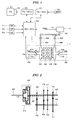
- FIG. 1 shows a configuration of an internal combustion engine and a transmission mechanism for driving a vehicle according to one embodiment of the present invention and a control system therefor;
- FIG. 2 illustrates a configuration of the transmission shown in FIG. 1 ;
- FIG. 3A to 3H show time charts for illustrating a control upon deceleration of the vehicle
- FIG. 4 is a time chart for illustrating a vehicle stabilizing control
- FIG. 5 is a flowchart of a process for performing an output torque control of the internal combustion engine.
- FIG. 1 shows a configuration of an internal combustion engine and a transmission mechanism for driving a vehicle according to one embodiment of the present invention and a control system therefor.
- a V-type six-cylinder internal combustion engine (hereinafter referred to as "engine") 1 has a first bank 2A provided with #1 - #3 cylinders (first cylinder group) and a second bank 2B provided with #4 - #6 cylinders (second cylinder group).
- An intake system corresponding to the first bank 2A includes a first chamber 3A, a first intake passage 4A, and branch passages connecting the first chamber 3A to #1 - #3 cylinders.
- the first intake passage 4A is provided with a first throttle valve 5A.
- the first throttle valve 5A is provided with a first throttle valve opening sensor 7A for detecting an opening of the throttle valve 5A, and the detection signal of the sensor 7A is supplied to an electronic control unit 20 for the engine control (hereinafter referred to as "EC-ECU").
- the first throttle valve 5A is connected to a first actuator 6A for actuating the throttle valve 5A, and the operation of the first actuator 6A is controlled by the EG-ECU 20.
- An intake system corresponding to the second bank 2B includes a second chamber 3B, a second intake passage 4B, and branch passages connecting the second chamber 3B to #4 - #6 cylinders.
- the second intake passage 4B is provided with a second throttle valve 5B.
- the second throttle valve 5B is provided with a second throttle valve opening sensor 7B for detecting an opening of the throttle valve 5B, and the detection signal of the sensor 7B is supplied to the EG-ECU 20.
- the second throttle valve 5B is connected to a second actuator 6B for actuating the throttle valve 5B, and the operation of the second actuator 6B is controlled by the EG-ECU 20.
- the connecting lines from the EG-ECU 20 to the second actuator 6B and the second throttle valve opening sensor 7B are not shown.
- the branch passages connected respectively to #1 - #6 cylinders are provided with a fuel injection valve (not shown), and the fuel injection timing and fuel injection period of each fuel injection valve is controlled by the EG-ECU 20.
- the first and second chambers 3A and 3B are connected via first and second connecting passages 8A and 8B, and a third connecting passage 10 to a negative pressure chamber of a brake booster 11.
- the first and second connecting passages 8A and 8B are respectively provided with first and second check valves 9A and 9B.
- the first check valve 9A opens when the pressure PBNA in the negative pressure chamber of the brake booster 11 (hereinafter referred to as "BRB absolute pressure PBNA”) is higher than the intake pressure PBA1 in the first chamber 3A, to supply the negative pressure in the first chamber 3A to the negative pressure chamber of the brake booster 11.
- BRB absolute pressure PBNA the pressure PBNA in the negative pressure chamber of the brake booster 11
- the second check valve 9B opens when the BRB absolute pressure PBNA is higher than the intake pressure PBA2 in the second chamber 3B, to supply the negative pressure in the second chamber 3B to the negative pressure chamber of the brake booster 11.
- the brake booster 11 is provided with a negative pressure sensor 12 for detecting a pressure difference PBN between the pressure PBNA in the negative pressure chamber and the atmospheric pressure PA (herein after referred to as "BRB negative pressure PBN").
- the detection signal of the sensor 12 is supplied to the EG-ECU 20.
- the BRB negative pressure PBN takes a value corresponding to the difference (PA - PBNA), and increases as the BRB absolute pressure PBNA decreases.
- the brake booster I is configured so that the negative pressure is applied to a diaphragm according to a depressing amount of the brake pedal (not shown) of the vehicle, to increase the brake operation force.
- An accelerator sensor 21 for detecting a depression amount (hereinafter referred to as "accelerator operation amount”) AP of the accelerator pedal of the vehicle driven by the engine 1, a vehicle speed sensor 22 for detecting a vehicle speed VP of the vehicle, and an engine rotational speed sensor 23 for detecting an rotational speed NE of the engine 1, are connected to the EG-ECU 20.
- the detection signals of these sensors are supplied to the EG-ECU 20.
- the EG-ECU 20 is connected to an electronic control unit 30 (hereinafter referred to as "TM-ECU 30") for controlling an automatic transmission 31 through an oil pressure control unit 32, and another electronic control unit 33 for performing the vehicle stabilizing control (hereinafter referred to as "VC-ECU 33").
- TM-ECU 30 electronice control unit 30
- VC-ECU 33 vehicle stabilizing control
- the TM-ECU 30 transmits a signal indicative of an engine demand torque which is necessary upon the shift change of the transmission, to the EG-ECU 20. For example, when performing the shift-down, the TM-ECU 30 transmits a signal demanding the blipping control for increasing the engine output so as to temporarily increase the engine rotational speed NE, to the EG-ECU 20.
- a driving wheel speed sensor 34 for detecting a driving wheel speed VDW of the vehicle is connected to the VC-ECU 33.
- the VC-ECU 33 transmits a signal demanding the vehicle stabilizing control for temporarily increasing the engine output.
- the EG-ECU 20 includes an input circuit having various functions including shaping the waveforms of input signals from the various sensors, correcting the voltage levels of the input signals to a predetermined level, and converting analog signal values into digital signal values.
- the EG-ECU 20 further includes a central processing unit (hereinafter referred to as "CPU"), a memory circuit, and an output circuit.
- the memory circuit preliminarily stores various operating programs to be executed by the CPU and the computation results or the like by the CPU.
- the output circuit supplies drive signals to the actuators 6A and 6B, the fuel injection valves, and the like.
- the TM-ECU 30 and VC-ECU 33 are basically configured similarly to the EG-ECU 20.
- the EG-ECU 20 performs an opening period control of the fuel injection valves and an ignition timing control as well as a throttle valve opening control.
- target openings THCMDA and THCMDB is calculated according to the engine demand torque and the actuators 6A and 6B is actuated so that the detected throttle valve opening THA and THB respectively coincide with the target openings THCMDA and THCMDB.
- the target openings THCMDA and THCMDB are calculated according to a demand torque TRQCMD of the engine 1 and the throttle valve openings THA and THB are controlled so that the output torque of the engine 1 coincides with the demand torque TRQCMD.
- the crankshaft of the engine 1 is connected to the automatic transmission 31 and the output shaft of the automatic transmission 31 drives driving wheels of the vehicle through a drivetrain mechanism (not shown).
- the automatic transmission 31 is a dual clutch transmission including two clutches, and hereinafter referred to as "DCT 31 ".
- the TM-ECU 30 is connected to a shift lever switch, paddle switches, and the like, and performs the automatic shift-change control based on the accelerator pedal operation amount AP, vehicle speed VP, engine rotational speed NE, and the like, or performs the shift-change control according to the driver's instruction.
- FIG. 2 shows a part of simplified configuration of the DCT 31, in which 1st to 4th speed gears are shown.
- the crankshaft 40 of the engine 1 is connected to a clutch mechanism 41 which includes a first clutch 42 connected to a first main shaft 44, and a second clutch 43 connected to a second main shaft 45.
- first drive gear 46 and a third drive gear 47 are supported, and a second drive gear 48 and a fourth drive gear 49 are supported on the second main shaft 45.
- a first driven gear 51, a second driven gear 52, a third driven gear 53, and a fourth driven gear 54 are supported on an output shaft 55.
- the shift-down of the DCT 31 is performed in two modes.
- the first shift-down mode for example, the shift-down from 4th-speed position to 3rd-speed position is performed as follows.
- the second clutch 43 is disengaged (the first clutch is disengaged when 4th-speed position is selected), the mesh between the fourth drive gear 49 and the fourth driven gear 54 is released, the 3rd drive gear 47 is meshed with the third driven gear 53, and the first clutch 42 is engaged.
- the third drive gear 47 may be meshed with the third driven gear 53 before or immediately after the beginning of the shift-down, since the first clutch 42 is disengaged when the 4th-speed position is selected.
- the torque transmission through the clutch mechanism 41 is cut for a certain time period.
- the demand signal for the blipping control is transferred from the TM-ECU 30 to the EG-ECU 20 when the torque transmission through the clutch mechanism 41 is cut.
- the third drive gear 47 is meshed with the third driven gear 53 before or immediately after the beginning of the shift-down when the 4th-speed position is selected, and the engaging operation in which the engaging force of the first clutch 42 is gradually increased is performed in parallel with the disengaging operation in which the engaging force of the second clutch 43 is gradually reduced.
- the shift-down can be performed with maintaining the driving force transmission through the clutch mechanism 41.
- the fourth drive gear 49 is meshed with the fourth driven gear 54 at the beginning of the shift-up when the 3rd-speed position is selected, and the disengaging operation in which the engaging force of the first clutch 42 is gradually reduced is performed in parallel with the engaging operation in which the engaging force of the second clutch 43 is gradually increased. Accordingly, the shift-up is performed under the condition where the throttle valves 5A and 5B are opened according to the demand torque (accelerator pedal operation amount AP) of the driver of the vehicle.
- FIGs. 3A - 3H and FIG. 4 are time charts for illustrating the output torque control of the engine 1 in this embodiment.
- FIGs. 3A - 3H show an example where the shift-up is performed at times t1 and t2; the accelerator pedal is returned at time t3; the brake pedal is depressed at time t4 immediately after t3, to start a rapid deceleration which continues to time t14; and the brake pedal is returned and the accelerator pedal is depressed at time t14 to start an acceleration again.
- TRDEC rapid deceleration
- the shift-down is performed three times (t6, t9, t12), and the shift-up is performed at times t15 and t16 after the start of the acceleration.
- FIG. 4 shows changes in the average value VDWA of the driving wheel speeds of the right and left driving wheels of the vehicle (VDWA will be hereinafter referred to simply as "driving wheel speed").
- the driving wheel speed VDWA rapidly decreases and immediately returns to the original state (shown by the dotted line).
- the stabilization demand torque TRQST is transferred from the VS-ECU 33 to the EG-ECU 20 as shown in FIG. 3F , to perform the vehicle stabilizing control in which the engine output torque is increased.
- the driving wheel speed VDWA returns to the original state immediately after the rapid decrease. It is to be noted that the vehicle stabilizing control is restarted if the rapid decrease in the driving wheel speed VDWA occurs again (time t5' in FIG. 4 ).
- the vehicle stabilizing control is performed during the periods of t5 - t6, t7 - t8, and t10 - t11.
- the blipping control is performed during the periods of t6 - t7, t9 - t10, and t12 - t13, wherein the engine output torque is temporarily increased.
- the throttle valves 5A and 5B Upon deceleration of the vehicle, the throttle valves 5A and 5B are normally fully closed and the negative pressure is consequently supplied from the intake passages 4A and 4B to the brake booster 11.
- the throttle valves 5A and 5B When performing the blipping control or the vehicle stabilizing control, the throttle valves 5A and 5B are opened.
- the brake pedal is strongly depressed, which reduces the negative pressure in the brake booster 11, and the supply of negative pressure is not sufficient due to the opening operation of the throttle valves 5A and 5B. Accordingly, shortage of the brake operation assisting force of the brake booster 11 may be caused.
- the opening state of the throttle valves 5A and 5B is maintained upon the shift-up of the transmission, which is also one of the factors causing shortage of the negative pressure in the brake booster 11.
- the output torque control of the engine 1 is performed with the process shown in FIG. 5 , to ensure the negative pressure in the brake booster 11.
- the process shown in FIG. 5 is executed at predetermined time intervals by the CPU in the EG-ECU 20.
- step S11 it is determined whether or not the vehicle is during deceleration. If the answer to step S11 is negative (NO), the normal output torque control is performed (step S13). If the answer to step S11 is affirmative (YES), it is determined whether or not a torque increase flag FTINC is "1" (step S14). The torque increase flag is set to "1" when the request for the blipping control or the vehicle stability control is received. If the torque increase flag FTINC is "0", the process proceeds to step S13.
- step S14 it is determined whether or not the BRB negative pressure PBN is equal to or less than a first threshold value PBN1 (e.g., 65 kPa) (step S14). If the answer to step S14 is negative (NO), the negative pressure in the brake booster is determined to be sufficient, and the blipping control or the vehicle stabilizing control is performed by opening both of the first and second throttle valves 5A and 5B (steps S15 and S16). Requested one of the blipping control and the vehicle stabilizing control is performed although steps S 15 and S 16 are shown in series in FIG. 5 .
- a first threshold value PBN1 e.g. 65 kPa
- step S14 If the answer to step S14 is affirmative (YES), i.e., the BRB negative pressure PBN is equal to or less than the first threshold value PBN1, it is further determined whether or not the BRB negative pressure is equal to or less than a second threshold value PMN2 (e.g., 50 kPa) which is less than the fist threshold value PBN1 (step S17).
- a second threshold value PMN2 e.g., 50 kPa
- step S 17 If the answer to step S 17 is negative (NO), i.e., the BRB negative pressure PBN is greater than the second threshold value PBN2 and equal to or less than the first threshold value PBN1, the blipping control is performed by opening both of the first and second throttle valves 5A and 5B, or the vehicle stabilizing control is performed by opening only the first throttle valve 5A (steps S18 and S19). Requested one of the blipping control and the vehicle stabilizing control is performed although steps S18 and S 19 are shown in series in FIG. 5 .
- step S17 If the answer to step S17 is affirmative (YES), i.e., the BRB negative pressure PBN is equal to or less than the second threshold value PBN2, the blipping control or the vehicle stabilizing control is performed by opening only the first throttle valve 5A (steps S20 and S21). Requested one of the blipping control and the vehicle stabilizing control is performed although steps S20 and S21 are shown in series in FIG. 5 .
- Both of the blipping control and the vehicle stabilizing control may possibly be requested. In such case, the control with a greater demand torque is selected to be performed in this embodiment.
- the vehicle stabilizing control is performed by opening only the first throttle valve 5A if the BRB negative pressure is equal to or less than the first threshold value PBN1 indicating that the assisting force of the brake booster has decreased. Consequently, the second throttle valve 5B is maintained at the closed state, and the negative pressure is supplied from the second intake system to the brake booster 11. to ensure sufficient assisting force of the brake booster 11.
- the vehicle stabilizing control and the blipping control are performed by opening only the first throttle valve 5A if the BRB negative pressure PBN is equal to or less than the second threshold value; 2) the vehicle stabilizing control is performed by opening only the first throttle valve 5A and the blipping control is performed by opening the first and second throttle valves 5A and 5B if the BRB negative pressure is greater than the second threshold value PBN2 and equal to or less than the first threshold value PBN1; and 3) the vehicle stabilizing control and the blipping control are performed by opening the first and second throttle valves 5A and 5B if the BRB negative pressure PBN is greater than the first threshold value PBN1.
- the output torque increase control can appropriately be performed according to a degree of shortage of the BRB negative pressure PBN, i.e., the assisting force of the brake booster 11.
- PBN the BRB negative pressure
- PBN the degree of shortage of the assisting force of the brake booster 11
- the engine output torque can rapidly be increased upon shift-down of the transmission, thereby rapidly completing the shift-down.
- the shift-up of the transmission is performed with maintaining the driving force transmission through the clutch mechanism 41 and the openings of the first and second throttle valve are controlled according to the demand output of the driver (accelerator pedal operation amount AP).
- the throttle valves 5A and 5B are opened upon the shift-up of the transmission. Accordingly, the BRB negative pressure PBN may possibly be reduced by performing the shift-up of the transmission. Therefore, it is more advantageous to the vehicle having the dual clutch mechanism to appropriately perform the engine output increase control upon vehicle deceleration by opening only the first throttle valve 5A.
- the negative pressure sensor 12 corresponds to the pressure parameter detecting means
- the driving wheel speed sensor 34 is corresponds to the driving wheel speed detecting means.
- the first actuator 6A constitutes a part of the one-throttle vale control means and a part of the two-throttle valve control means
- the second actuator 6B constitutes a part of the two-throttle valve control means.
- the EG-ECU 20 constitutes the output increase control means, a part of the one-throttle valve control means, a part of the two-throttle valve control means, and the shift-up control means.
- steps S14 to S21 correspond to the output increase control means
- steps S19 to S21 correspond to the one-throttle valve control means
- steps S15, S16, and S 18 correspond to the two-throttle valve control means.
- the present invention is not limited to the above-described embodiment, and various modifications may be made.
- the control system which performs the blipping control and the vehicle stabilizing control as the engine output torque increase control upon vehicle deceleration is shown.
- the present invention is applicable to the control system which performs only one of the blipping control and the vehicle stabilizing control.
- the second throttle valve 5B may be opened instead of the first throttle valve 5A when opening only one throttle valve.
- a BRB absolute pressure PBNA which is an absolute pressure in the negative pressure chamber of the brake booster, may be detected, and a pressure difference (PAO - PBNA) between a reference atmospheric pressure PAO (e.g., 1 atm (101.3 kPa)) and the BRB absolute pressure PBNA may be used as the pressure parameter indicative of the assisting force of the brake booster.
- PAO - PBNA a pressure difference between a reference atmospheric pressure PAO (e.g., 1 atm (101.3 kPa)) and the BRB absolute pressure PBNA may be used as the pressure parameter indicative of the assisting force of the brake booster.
- the DCT 31 is shown as the automatic transmission.
- the inventions recited in claims 1 to 4 may be applicable to a control system for an internal combustion engine for driving a vehicle having an Automated Manual Transmission with single clutch, or an automatic transmission with a torque converter.
- the present invention is applicable to a control system for an internal combustion engine having a plurality of intake systems (throttle valves) which are mutually independent of others, in addition to the V-type 6-cylinder internal combustion engine described above.
- the first and second intake systems correspond respectively to the first and second cylinder groups, and first and second throttle valves are provided respectively in the first and second intake systems.
- An output of the engine is reduced upon deceleration of a vehicle driven by the engine.
- a pressure parameter indicative of an assisting force generated by a brake booster is detected.
- An intake negative pressure is supplied to the brake booster from the first and second intake systems.
- One of the first and second throttle valves is opened to increase the engine output when the pressure parameter is equal to or less than a first threshold value which indicates that the assisting force of the brake booster has decreased.
Landscapes
- Engineering & Computer Science (AREA)
- Mechanical Engineering (AREA)
- Chemical & Material Sciences (AREA)
- Combustion & Propulsion (AREA)
- General Engineering & Computer Science (AREA)
- Transportation (AREA)
- Control Of Vehicle Engines Or Engines For Specific Uses (AREA)
- Control Of Driving Devices And Active Controlling Of Vehicle (AREA)
- Control Of Throttle Valves Provided In The Intake System Or In The Exhaust System (AREA)
- Electrical Control Of Air Or Fuel Supplied To Internal-Combustion Engine (AREA)
- Control Of Transmission Device (AREA)
Description
- The present invention relates to a control system for an internal combustion engine, and particularly to a control system for an internal combustion engine which has a plurality of cylinders consisting of two or more cylinder groups, and a plurality of intake systems respectively corresponding to the cylinder groups.
- The brake booster for assisting the driver in operating the brake pedal of the automobile is widely used. The brake booster uses a negative pressure (a pressure which is lower than the atmospheric pressure) generated in the intake system of the internal combustion engine, to generate the assisting force. Japanese Patent Laid-open No.
2000-120474 - This control system is proposed contemplating a tendency that the negative pressure in the brake booster becomes insufficient when performing the lean-burn operation of the engine. According to this control system, the partition valve provided in the passage connecting the two intake systems, is opened when the negative pressure in the brake booster is sufficient. On the other hand, when the negative pressure is insufficient, the partition valve is closed and the throttle valve in the first intake system is controlled to be slightly closed while the throttle valve in the second intake system is controlled to an opening which is suitable for the lean-burn operation. Consequently, the negative pressure is secured by the first intake system.
- When the brake pedal is operated and the vehicle is decreasing, an output of the engine for driving the vehicle may sometimes be increased for securing running stability of the vehicle. When the vehicle speed is decreasing, the throttle valve is normally fully-closed to secure a sufficient negative pressure. However, if the engine output is increased upon deceleration of the vehicle as described above, the negative pressure may become insufficient. Further, when performing the shift-down of the transmission upon vehicle deceleration, the blipping control wherein the engine output is temporarily increased so as to increase the engine rotational speed, is performed. Such blipping control is also one of the factors which make the negative pressure insufficient.
- The control system shown in JP-'474 is configured for securing the negative pressure when performing the lean-burn operation of the engine. Therefore, the problem due to the engine output increase control upon vehicle deceleration cannot be solved by the control system of JP-'474.
- The present invention was made contemplating the above described point, and an objective of the present invention is to provide a control system for an internal combustion engine having a plurality of intake systems corresponding to two or more cylinder groups, which is able to appropriately perform the engine output increase control upon vehicle deceleration, to prevent the negative pressure for securing the assisting force of the brake booster from becoming insufficient.
- To attain the above objective, the present invention provides a control system for an internal combustion engine having a plurality of cylinders including first and second cylinder groups (2A, 2B), first and second intake systems corresponding respectively to the first and second cylinder groups, and first and second throttle valves (5A, 5B) provided respectively in the first and second intake systems. The control system includes output increase control means, and pressure parameter detecting means. The output increase control means increases an output of the engine upon deceleration of a vehicle driven by the engine. The pressure parameter detecting means detects a pressure parameter (PBN) indicative of an assisting force generated by a brake booster (11) to which an intake negative pressure is supplied from the first and second intake systems. The output increase control means includes one-throttle valve control means for opening one of the first and second throttle valves (5A, 5B) to increase the engine output when the pressure parameter (PBN) is equal to or less than a first threshold value (PBN1) which indicates that the assisting force of the brake booster has decreased.
- With this configuration, when performing the output increase control for increasing the engine output upon deceleration of the vehicle, the pressure parameter indicative of the assisting force generated by the brake booster is detected. The intake negative pressure is supplied to the brake booster from the first and second intake systems. If the detected pressure parameter is equal to or less than the first threshold value indicating that the assisting force of the brake booster has decreased, one of the first and second throttle valves respectively provided in the first and second intake systems is opened. Accordingly, the negative pressure is supplied to the brake booster from the intake system in which the throttle valve is not opened, thereby making it possible to secure the assisting force of the brake booster.
- Preferably, the control system further includes driving wheel speed detecting means (34) for detecting a driving wheel speed (VBW) of the vehicle, and the output increase control means performs a vehicle stabilizing control in which the engine output is increased based on the driving wheel speed (VBW) upon deceleration of the vehicle.
- With this configuration, the vehicle stabilizing control in which the engine output is increased based on the driving wheel speed upon deceleration of the vehicle, is performed. If the driving wheels of the vehicle are locked by the braking upon vehicle deceleration, the driving wheel speed extremely decreases. In such case, by performing the vehicle stabilizing control that the throttle valve in one of the intake systems is opened to increase the engine output, it is possible to stabilize the vehicle behavior as well as to secure the negative pressure for the brake booster.
- Preferably, the vehicle includes an automatic transmission (31) connected to an output shaft of the engine, and the output increase control means further includes two-throttle valve control means for opening both of the first and second throttle valves (5A, 5B) to increase the engine output. The output increase control means uses the one-throttle valve control means when performing the vehicle stabilizing control, and selects one of the one-throttle valve control means and two-throttle valve control means according to the pressure parameter, to use the selected throttle valve control means, when performing a blipping control for increasing the engine output so as to increase an rotational speed of the engine upon shift-down of the automatic transmission (31).
- With this configuration, the one-throttle valve opening control is performed when performing the vehicle stabilizing control, and one of the one-throttle valve opening control and the two-throttle valve opening control is selected according to the pressure parameter when performing the blipping control. In the two-throttle valve opening control, both of the first and second throttle valve is opened to increase the engine output. It is possible to perform a part of the output increase control with the two-throttle valve opening control, if the pressure parameter is comparatively great, i.e., the degree of shortage of the assisting force of the brake booster is small. Therefore, by applying the one-throttle valve opening control to the vehicle stabilizing control and applying the two-throttle valve opening control to the blipping control when the pressure parameter is comparatively great, the engine output can rapidly be increased when performing the shift-down of the transmission, thereby rapidly completing the shift-down.
- Preferably, the output increase control means performs the vehicle stabilizing control and the blipping control using the one-throttle valve control means when the pressure parameter (PBN) is equal to or less than a second threshold value (PBN2) which is less than the first threshold value (PBN2); the output increase control means performs the vehicle stabilizing control using the one-throttle valve control means and performs the blipping control using the two-throttle valve control means, when the pressure parameter (PBN) is greater than the second threshold value (PBN2) and equal to or less than the first threshold value (PBN1); and the output increase control means performs the vehicle stabilizing control and the blipping control using the two-throttle valve control means when the pressure parameter (PBN) is greater than the first threshold value (PBNI).
- With this configuration, the vehicle stabilizing control and the blipping control are performed with the one-throttle valve opening control when the pressure parameter is equal to or less than the second threshold value which is less than the first threshold value; the vehicle stabilizing control is performed with the one-throttle valve opening control and the blipping control is performed with the two-throttle valve opening control, when the pressure parameter is greater than the second threshold value and equal to or less than the first threshold value; and the vehicle stabilizing control and the blipping control are performed with the two-throttle valve opening control when the pressure parameter is greater than the first threshold value. Therefore, the engine output increase control can appropriately be performed according to the pressure parameter, i.e., the degree of shortage of the assisting force of the brake booster.
- Preferably, the automatic transmission (31) includes a clutch mechanism (42) having two clutches, and the shift-change of the automatic transmission can be performed with maintaining the driving force transmission through the clutch mechanism, and the control system further includes shift-up control means for controlling the openings of the first and second throttle valves (5A, 5B) according to an engine output demanded by the driver of the vehicle.
- With this configuration, the shift-up of the transmission is performed with maintaining the driving force transmission through the clutch mechanism and the openings of the first and second throttle valve are controlled according to the engine output demanded by the driver. In the vehicle having the automatic transmission including the dual clutch mechanism, the throttle valves are opened according the demand engine output of the driver upon the shift-up of the transmission. Accordingly, the pressure parameter is reduced by performing the shift-up of the transmission. Therefore, it is more advantageous to the vehicle having the dual clutch mechanism to perform the engine output increase control upon deceleration of the vehicle with the one-throttle valve opening control.
-
FIG. 1 shows a configuration of an internal combustion engine and a transmission mechanism for driving a vehicle according to one embodiment of the present invention and a control system therefor; -
FIG. 2 illustrates a configuration of the transmission shown inFIG. 1 ; -
FIG. 3A to 3H show time charts for illustrating a control upon deceleration of the vehicle; -
FIG. 4 is a time chart for illustrating a vehicle stabilizing control; and -
FIG. 5 is a flowchart of a process for performing an output torque control of the internal combustion engine. - Preferred embodiments of the present invention will now be described with reference to the drawings.
-
FIG. 1 shows a configuration of an internal combustion engine and a transmission mechanism for driving a vehicle according to one embodiment of the present invention and a control system therefor. A V-type six-cylinder internal combustion engine (hereinafter referred to as "engine") 1 has afirst bank 2A provided with #1 - #3 cylinders (first cylinder group) and asecond bank 2B provided with #4 - #6 cylinders (second cylinder group). - An intake system corresponding to the
first bank 2A includes afirst chamber 3A, afirst intake passage 4A, and branch passages connecting thefirst chamber 3A to #1 - #3 cylinders. Thefirst intake passage 4A is provided with afirst throttle valve 5A. Thefirst throttle valve 5A is provided with a first throttlevalve opening sensor 7A for detecting an opening of thethrottle valve 5A, and the detection signal of thesensor 7A is supplied to anelectronic control unit 20 for the engine control (hereinafter referred to as "EC-ECU"). Thefirst throttle valve 5A is connected to afirst actuator 6A for actuating thethrottle valve 5A, and the operation of thefirst actuator 6A is controlled by the EG-ECU 20. - An intake system corresponding to the
second bank 2B includes asecond chamber 3B, asecond intake passage 4B, and branch passages connecting thesecond chamber 3B to #4 - #6 cylinders. Thesecond intake passage 4B is provided with asecond throttle valve 5B. Thesecond throttle valve 5B is provided with a second throttlevalve opening sensor 7B for detecting an opening of thethrottle valve 5B, and the detection signal of thesensor 7B is supplied to the EG-ECU 20. Thesecond throttle valve 5B is connected to asecond actuator 6B for actuating thethrottle valve 5B, and the operation of thesecond actuator 6B is controlled by the EG-ECU 20. InFIG. 1 , the connecting lines from the EG-ECU 20 to thesecond actuator 6B and the second throttlevalve opening sensor 7B are not shown. - The branch passages connected respectively to #1 - #6 cylinders are provided with a fuel injection valve (not shown), and the fuel injection timing and fuel injection period of each fuel injection valve is controlled by the EG-
ECU 20. - The first and
second chambers passages passage 10 to a negative pressure chamber of abrake booster 11. The first and second connectingpassages second check valves first check valve 9A opens when the pressure PBNA in the negative pressure chamber of the brake booster 11 (hereinafter referred to as "BRB absolute pressure PBNA") is higher than the intake pressure PBA1 in thefirst chamber 3A, to supply the negative pressure in thefirst chamber 3A to the negative pressure chamber of thebrake booster 11. Thesecond check valve 9B opens when the BRB absolute pressure PBNA is higher than the intake pressure PBA2 in thesecond chamber 3B, to supply the negative pressure in thesecond chamber 3B to the negative pressure chamber of thebrake booster 11. - The
brake booster 11 is provided with anegative pressure sensor 12 for detecting a pressure difference PBN between the pressure PBNA in the negative pressure chamber and the atmospheric pressure PA (herein after referred to as "BRB negative pressure PBN"). The detection signal of thesensor 12 is supplied to the EG-ECU 20. The BRB negative pressure PBN takes a value corresponding to the difference (PA - PBNA), and increases as the BRB absolute pressure PBNA decreases. - The brake booster I is configured so that the negative pressure is applied to a diaphragm according to a depressing amount of the brake pedal (not shown) of the vehicle, to increase the brake operation force.
- An
accelerator sensor 21 for detecting a depression amount (hereinafter referred to as "accelerator operation amount") AP of the accelerator pedal of the vehicle driven by theengine 1, avehicle speed sensor 22 for detecting a vehicle speed VP of the vehicle, and an enginerotational speed sensor 23 for detecting an rotational speed NE of theengine 1, are connected to the EG-ECU 20. The detection signals of these sensors are supplied to the EG-ECU 20. - The EG-
ECU 20 is connected to an electronic control unit 30 (hereinafter referred to as "TM-ECU 30") for controlling anautomatic transmission 31 through an oilpressure control unit 32, and anotherelectronic control unit 33 for performing the vehicle stabilizing control (hereinafter referred to as "VC-ECU 33"). The ECU's 20, 30, and 33 mutually transmit necessary data and command signals to each other. - The TM-
ECU 30 transmits a signal indicative of an engine demand torque which is necessary upon the shift change of the transmission, to the EG-ECU 20. For example, when performing the shift-down, the TM-ECU 30 transmits a signal demanding the blipping control for increasing the engine output so as to temporarily increase the engine rotational speed NE, to the EG-ECU 20. - A driving
wheel speed sensor 34 for detecting a driving wheel speed VDW of the vehicle is connected to the VC-ECU 33. The VC-ECU 33 transmits a signal demanding the vehicle stabilizing control for temporarily increasing the engine output. - The EG-
ECU 20 includes an input circuit having various functions including shaping the waveforms of input signals from the various sensors, correcting the voltage levels of the input signals to a predetermined level, and converting analog signal values into digital signal values. The EG-ECU 20 further includes a central processing unit (hereinafter referred to as "CPU"), a memory circuit, and an output circuit. The memory circuit preliminarily stores various operating programs to be executed by the CPU and the computation results or the like by the CPU. The output circuit supplies drive signals to theactuators ECU 30 and VC-ECU 33 are basically configured similarly to the EG-ECU 20. - The EG-
ECU 20 performs an opening period control of the fuel injection valves and an ignition timing control as well as a throttle valve opening control. In the throttle valve opening control, target openings THCMDA and THCMDB is calculated according to the engine demand torque and theactuators engine 1 and the throttle valve openings THA and THB are controlled so that the output torque of theengine 1 coincides with the demand torque TRQCMD. - The crankshaft of the
engine 1 is connected to theautomatic transmission 31 and the output shaft of theautomatic transmission 31 drives driving wheels of the vehicle through a drivetrain mechanism (not shown). - In this embodiment, the
automatic transmission 31 is a dual clutch transmission including two clutches, and hereinafter referred to as "DCT 31 ". - The TM-
ECU 30 is connected to a shift lever switch, paddle switches, and the like, and performs the automatic shift-change control based on the accelerator pedal operation amount AP, vehicle speed VP, engine rotational speed NE, and the like, or performs the shift-change control according to the driver's instruction. -
FIG. 2 shows a part of simplified configuration of theDCT 31, in which 1st to 4th speed gears are shown. Thecrankshaft 40 of theengine 1 is connected to aclutch mechanism 41 which includes a first clutch 42 connected to a firstmain shaft 44, and a second clutch 43 connected to a secondmain shaft 45. - On the first
main shaft 44, afirst drive gear 46 and athird drive gear 47 are supported, and asecond drive gear 48 and afourth drive gear 49 are supported on the secondmain shaft 45. A first drivengear 51, a second drivengear 52, a third drivengear 53, and a fourth drivengear 54 are supported on anoutput shaft 55. - Engagement and disengagement of the first and
second clutches pressure control unit 32. - In this embodiment, the shift-down of the
DCT 31 is performed in two modes. In the first shift-down mode, for example, the shift-down from 4th-speed position to 3rd-speed position is performed as follows. The second clutch 43 is disengaged (the first clutch is disengaged when 4th-speed position is selected), the mesh between thefourth drive gear 49 and the fourth drivengear 54 is released, the3rd drive gear 47 is meshed with the third drivengear 53, and the first clutch 42 is engaged. Alternatively, thethird drive gear 47 may be meshed with the third drivengear 53 before or immediately after the beginning of the shift-down, since the first clutch 42 is disengaged when the 4th-speed position is selected. In the first shift-down mode, the torque transmission through theclutch mechanism 41 is cut for a certain time period. The demand signal for the blipping control is transferred from the TM-ECU 30 to the EG-ECU 20 when the torque transmission through theclutch mechanism 41 is cut. - In the second shift-down mode, the
third drive gear 47 is meshed with the third drivengear 53 before or immediately after the beginning of the shift-down when the 4th-speed position is selected, and the engaging operation in which the engaging force of the first clutch 42 is gradually increased is performed in parallel with the disengaging operation in which the engaging force of the second clutch 43 is gradually reduced. In the second shift-down mode, the shift-down can be performed with maintaining the driving force transmission through theclutch mechanism 41. - When performing the shift-up of the DCT 31 (e.g., from 3rd-speed position to 4th-speed position), the
fourth drive gear 49 is meshed with the fourth drivengear 54 at the beginning of the shift-up when the 3rd-speed position is selected, and the disengaging operation in which the engaging force of the first clutch 42 is gradually reduced is performed in parallel with the engaging operation in which the engaging force of the second clutch 43 is gradually increased. Accordingly, the shift-up is performed under the condition where thethrottle valves -
FIGs. 3A - 3H andFIG. 4 are time charts for illustrating the output torque control of theengine 1 in this embodiment.FIGs. 3A - 3H show an example where the shift-up is performed at times t1 and t2; the accelerator pedal is returned at time t3; the brake pedal is depressed at time t4 immediately after t3, to start a rapid deceleration which continues to time t14; and the brake pedal is returned and the accelerator pedal is depressed at time t14 to start an acceleration again. During the rapid deceleration TRDEC (t4 - t14), the shift-down is performed three times (t6, t9, t12), and the shift-up is performed at times t15 and t16 after the start of the acceleration. -
FIG. 4 shows changes in the average value VDWA of the driving wheel speeds of the right and left driving wheels of the vehicle (VDWA will be hereinafter referred to simply as "driving wheel speed"). Specifically, in the example ofFIG. 4 , the driving wheel speed VDWA rapidly decreases and immediately returns to the original state (shown by the dotted line). In this embodiment, when the driving wheel speed VDWA rapidly decreases, the stabilization demand torque TRQST is transferred from the VS-ECU 33 to the EG-ECU 20 as shown inFIG. 3F , to perform the vehicle stabilizing control in which the engine output torque is increased. According to the vehicle stabilizing control, the driving wheel speed VDWA returns to the original state immediately after the rapid decrease. It is to be noted that the vehicle stabilizing control is restarted if the rapid decrease in the driving wheel speed VDWA occurs again (time t5' inFIG. 4 ). - In the example shown in
FIGs. 3A - 3H , the vehicle stabilizing control is performed during the periods of t5 - t6, t7 - t8, and t10 - t11. - Further, as shown in
FIG. 3G , the blipping control is performed during the periods of t6 - t7, t9 - t10, and t12 - t13, wherein the engine output torque is temporarily increased. - Upon deceleration of the vehicle, the
throttle valves intake passages brake booster 11. When performing the blipping control or the vehicle stabilizing control, thethrottle valves brake booster 11, and the supply of negative pressure is not sufficient due to the opening operation of thethrottle valves brake booster 11 may be caused. - Further, in this embodiment, the opening state of the
throttle valves brake booster 11. - Therefore, in this embodiment, the output torque control of the
engine 1 is performed with the process shown inFIG. 5 , to ensure the negative pressure in thebrake booster 11. The process shown inFIG. 5 is executed at predetermined time intervals by the CPU in the EG-ECU 20. - In step S11, it is determined whether or not the vehicle is during deceleration. If the answer to step S11 is negative (NO), the normal output torque control is performed (step S13). If the answer to step S11 is affirmative (YES), it is determined whether or not a torque increase flag FTINC is "1" (step S14). The torque increase flag is set to "1" when the request for the blipping control or the vehicle stability control is received. If the torque increase flag FTINC is "0", the process proceeds to step S13.
- If the torque increase flag FTINC is "1", it is determined whether or not the BRB negative pressure PBN is equal to or less than a first threshold value PBN1 (e.g., 65 kPa) (step S14). If the answer to step S14 is negative (NO), the negative pressure in the brake booster is determined to be sufficient, and the blipping control or the vehicle stabilizing control is performed by opening both of the first and
second throttle valves FIG. 5 . - If the answer to step S14 is affirmative (YES), i.e., the BRB negative pressure PBN is equal to or less than the first threshold value PBN1, it is further determined whether or not the BRB negative pressure is equal to or less than a second threshold value PMN2 (e.g., 50 kPa) which is less than the fist threshold value PBN1 (step S17).
- If the answer to step S 17 is negative (NO), i.e., the BRB negative pressure PBN is greater than the second threshold value PBN2 and equal to or less than the first threshold value PBN1, the blipping control is performed by opening both of the first and
second throttle valves first throttle valve 5A (steps S18 and S19). Requested one of the blipping control and the vehicle stabilizing control is performed although steps S18 andS 19 are shown in series inFIG. 5 . - If the answer to step S17 is affirmative (YES), i.e., the BRB negative pressure PBN is equal to or less than the second threshold value PBN2, the blipping control or the vehicle stabilizing control is performed by opening only the
first throttle valve 5A (steps S20 and S21). Requested one of the blipping control and the vehicle stabilizing control is performed although steps S20 and S21 are shown in series inFIG. 5 . - Both of the blipping control and the vehicle stabilizing control may possibly be requested. In such case, the control with a greater demand torque is selected to be performed in this embodiment.
- According to the process of
FIG. 5 , when performing the torque increase control in which the engine output is increased upon vehicle deceleration, the vehicle stabilizing control is performed by opening only thefirst throttle valve 5A if the BRB negative pressure is equal to or less than the first threshold value PBN1 indicating that the assisting force of the brake booster has decreased. Consequently, thesecond throttle valve 5B is maintained at the closed state, and the negative pressure is supplied from the second intake system to thebrake booster 11. to ensure sufficient assisting force of thebrake booster 11. - Further, 1) the vehicle stabilizing control and the blipping control are performed by opening only the
first throttle valve 5A if the BRB negative pressure PBN is equal to or less than the second threshold value; 2) the vehicle stabilizing control is performed by opening only thefirst throttle valve 5A and the blipping control is performed by opening the first andsecond throttle valves second throttle valves - Accordingly, the output torque increase control can appropriately be performed according to a degree of shortage of the BRB negative pressure PBN, i.e., the assisting force of the
brake booster 11. If the BRB negative pressure PBN is comparatively great (PBN is equal to or greater than PBN2), i.e., the degree of shortage of the assisting force of thebrake booster 11 is comparatively small, by performing the blipping control by opening the two throttle valves, the engine output torque can rapidly be increased upon shift-down of the transmission, thereby rapidly completing the shift-down. - Further, in this embodiment, the shift-up of the transmission is performed with maintaining the driving force transmission through the
clutch mechanism 41 and the openings of the first and second throttle valve are controlled according to the demand output of the driver (accelerator pedal operation amount AP). In theDCT 31 including theclutch mechanism 41, thethrottle valves first throttle valve 5A. - In this embodiment, the
negative pressure sensor 12 corresponds to the pressure parameter detecting means, and the drivingwheel speed sensor 34 is corresponds to the driving wheel speed detecting means. Thefirst actuator 6A constitutes a part of the one-throttle vale control means and a part of the two-throttle valve control means, and thesecond actuator 6B constitutes a part of the two-throttle valve control means. The EG-ECU 20 constitutes the output increase control means, a part of the one-throttle valve control means, a part of the two-throttle valve control means, and the shift-up control means. Specifically, steps S14 to S21 correspond to the output increase control means, steps S19 to S21 correspond to the one-throttle valve control means, and steps S15, S16, and S 18 correspond to the two-throttle valve control means. - The present invention is not limited to the above-described embodiment, and various modifications may be made. For example, in the above-described embodiment, the control system which performs the blipping control and the vehicle stabilizing control as the engine output torque increase control upon vehicle deceleration, is shown. The present invention is applicable to the control system which performs only one of the blipping control and the vehicle stabilizing control.
- Further, the
second throttle valve 5B may be opened instead of thefirst throttle valve 5A when opening only one throttle valve. - Further, a BRB absolute pressure PBNA which is an absolute pressure in the negative pressure chamber of the brake booster, may be detected, and a pressure difference (PAO - PBNA) between a reference atmospheric pressure PAO (e.g., 1 atm (101.3 kPa)) and the BRB absolute pressure PBNA may be used as the pressure parameter indicative of the assisting force of the brake booster.
- Further, in the above-described embodiment, the
DCT 31 is shown as the automatic transmission. The inventions recited inclaims 1 to 4 may be applicable to a control system for an internal combustion engine for driving a vehicle having an Automated Manual Transmission with single clutch, or an automatic transmission with a torque converter. - Further, the present invention is applicable to a control system for an internal combustion engine having a plurality of intake systems (throttle valves) which are mutually independent of others, in addition to the V-type 6-cylinder internal combustion engine described above.
- The present invention may be embodied in other specific forms without departing from the spirit or essential characteristics thereof. The presently disclosed embodiments are therefore to be considered in all respects as illustrative and not restrictive, the scope of the invention being indicated by the appended claims, rather than the foregoing description, and all changes which come within the meaning and range of equivalency of the claims are, therefore, to be embraced therein.
- A control system for an internal combustion engine having a plurality of cylinders including first and second cylinder groups. The first and second intake systems correspond respectively to the first and second cylinder groups, and first and second throttle valves are provided respectively in the first and second intake systems. An output of the engine is reduced upon deceleration of a vehicle driven by the engine. A pressure parameter indicative of an assisting force generated by a brake booster is detected. An intake negative pressure is supplied to the brake booster from the first and second intake systems. One of the first and second throttle valves is opened to increase the engine output when the pressure parameter is equal to or less than a first threshold value which indicates that the assisting force of the brake booster has decreased.
Claims (10)
- A control system for an internal combustion engine having a plurality of cylinders including first and second cylinder groups, first and second intake systems corresponding respectively to said first and second cylinder groups, and first and second throttle valves provided respectively in said first and second intake systems, said control system comprising:output increase control means for increasing an output of said engine upon deceleration of a vehicle driven by said engine; andpressure parameter detecting means for detecting a pressure parameter indicative of an assisting force generated by a brake booster to which an intake negative pressure is supplied from said first and second intake systems;wherein said output increase control means includes one-throttle valve control means for opening one of said first and second throttle valves to increase the engine output when the pressure parameter is equal to or less than a first threshold value which indicates that the assisting force of said brake booster has decreased.
- A control system according to claim 1, further including driving wheel speed detecting means for detecting a driving wheel speed of said vehicle,
wherein said output increase control means performs a vehicle stabilizing control in which the engine output is increased based on the driving wheel speed upon deceleration of said vehicle. - A control system according to claim 2, wherein said vehicle includes an automatic transmission connected to an output shaft of said engine, and said output increase control means further includes two-throttle valve control means for opening both of said first and second throttle valves to increase the engine output,
wherein said output increase control means uses said one-throttle valve control means when performing the vehicle stabilizing control, and selects one of said one-throttle valve control means and two-throttle valve control means according to the pressure parameter, to use the selected throttle valve control means, when performing a blipping control upon shift-down of said automatic transmission, the engine output being increased for increasing an rotational speed of said engine in the blipping control. - A control system according to claim 3, wherein said output increase control means performs the vehicle stabilizing control and the blipping control using said one-throttle valve control means when the pressure parameter is equal to or less than a second threshold value which is less than the first threshold value;
said output increase control means performs the vehicle stabilizing control using said one-throttle valve control means and performs the blipping control using said two-throttle valve control means, when the pressure parameter is greater than the second threshold value and equal to or less than the first threshold value; and
said output increase control means performs the vehicle stabilizing control and the blipping control using said two-throttle valve control means when the pressure parameter is greater than the first threshold value. - A control system according to claim 1, wherein said vehicle includes an automatic transmission connected to an output shaft of said engine, and said automatic transmission includes a clutch mechanism having two clutches,
wherein the shift-change of said automatic transmission can be performed with maintaining the driving force transmission through said clutch mechanism, and
said control system further includes shift-up control means for controlling the openings of said first and second throttles valves according to an engine output demanded by the driver of said vehicle. - A control method for an internal combustion engine having a plurality of cylinders including first and second cylinder groups, first and second intake systems corresponding respectively to said first and second cylinder groups, and first and second throttle valves provided respectively in said first and second intake systems, said control method comprising the steps of:a) increasing an output of said engine upon deceleration of a vehicle driven by said engine; andb) detecting a pressure parameter indicative of an assisting force generated by a brake booster to which an intake negative pressure is supplied from said first and second intake systems;wherein said step a) includes the step of c) opening one of said first and second throttle valves to increase the engine output when the pressure parameter is equal to or less than a first threshold value which indicates that the assisting force of said brake booster has decreased.
- A control method according to claim 6, further including the step of d) detecting a driving wheel speed of said vehicle,
wherein a vehicle stabilizing control is performed by said step a), the engine output being increased based on the driving wheel speed upon deceleration of said vehicle in the vehicle stabilizing control. - A control method according to claim 7, wherein said vehicle includes an automatic transmission connected to an output shaft of said engine, and said step a) further includes the step of e) opening both of said first and second throttle valves to increase the engine output,
wherein said step c) is used when performing the vehicle stabilizing control, and one of said steps c) and e) is selected according to the pressure parameter, and the selected step is used when performing a blipping control upon shift-down of said automatic transmission, the engine output being increased for increasing an rotational speed of said engine in the blipping control. - A control method according to claim 8, wherein the vehicle stabilizing control and the blipping control are performed using said step c) when the pressure parameter is equal to or less than a second threshold value which is less than the first threshold value;
the vehicle stabilizing control is performed using said step c) and the blipping control is performed using said step e), when the pressure parameter is greater than the second threshold value and equal to or less than the first threshold value; and
the vehicle stabilizing control and the blipping control are performed using said step e) when the pressure parameter is greater than the first threshold value. - A control method according to claim 6, wherein said vehicle includes an automatic transmission connected to an output shaft of said engine, and said automatic transmission includes a clutch mechanism having two clutches,
wherein the shift-change of said automatic transmission can be performed with maintaining the driving force transmission through said clutch mechanism, and
said control method further includes the step of f) controlling the openings of said first and second throttles valves according to an engine output demanded by the driver of said vehicle.
Applications Claiming Priority (1)
| Application Number | Priority Date | Filing Date | Title |
|---|---|---|---|
| JP2009170992A JP5261306B2 (en) | 2009-07-22 | 2009-07-22 | Control device for internal combustion engine |
Publications (2)
| Publication Number | Publication Date |
|---|---|
| EP2292911A1 EP2292911A1 (en) | 2011-03-09 |
| EP2292911B1 true EP2292911B1 (en) | 2012-01-04 |
Family
ID=42797294
Family Applications (1)
| Application Number | Title | Priority Date | Filing Date |
|---|---|---|---|
| EP10168330A Ceased EP2292911B1 (en) | 2009-07-22 | 2010-07-02 | Control system for internal combustion engine |
Country Status (3)
| Country | Link |
|---|---|
| US (1) | US8485157B2 (en) |
| EP (1) | EP2292911B1 (en) |
| JP (1) | JP5261306B2 (en) |
Families Citing this family (11)
| Publication number | Priority date | Publication date | Assignee | Title |
|---|---|---|---|---|
| JP2008190628A (en) * | 2007-02-05 | 2008-08-21 | Toyota Motor Corp | Drive force controller of vehicle |
| JP5261306B2 (en) * | 2009-07-22 | 2013-08-14 | 本田技研工業株式会社 | Control device for internal combustion engine |
| CN103649502B (en) * | 2011-07-26 | 2016-04-13 | 株式会社F.C.C. | Vehicle power transmission system |
| DE102011080404B4 (en) * | 2011-08-04 | 2024-09-26 | Robert Bosch Gmbh | Method for determining a functional state of a pressure build-up valve and function monitoring device for a pressure build-up valve of a hydraulic brake booster device |
| JP5856779B2 (en) * | 2011-08-10 | 2016-02-10 | アイシン・エーアイ株式会社 | transmission |
| US8176894B2 (en) | 2011-09-22 | 2012-05-15 | Ford Global Technologies, Llc | Vacuum system for an engine |
| JP5836048B2 (en) * | 2011-10-11 | 2015-12-24 | アイシン・エーアイ株式会社 | transmission |
| WO2013125693A1 (en) * | 2012-02-24 | 2013-08-29 | アイシン・エィ・ダブリュ株式会社 | Control device |
| WO2016058092A1 (en) * | 2014-10-16 | 2016-04-21 | Griffin Innovation | Mobile device systems and methods |
| US10138819B2 (en) * | 2014-12-09 | 2018-11-27 | Kawasaki Jukogyo Kabushiki Kaisha | Vehicle, straddle-type vehicle, and method of driving throttle valve |
| JP7509000B2 (en) | 2020-11-05 | 2024-07-02 | マツダ株式会社 | Vehicle power transmission system |
Family Cites Families (10)
| Publication number | Priority date | Publication date | Assignee | Title |
|---|---|---|---|---|
| JPH05208666A (en) * | 1992-01-31 | 1993-08-20 | Mazda Motor Corp | Automatic brake device for vehicle |
| JP3003528B2 (en) | 1994-12-14 | 2000-01-31 | トヨタ自動車株式会社 | Negative pressure control device for internal combustion engine |
| JP3484342B2 (en) | 1998-04-15 | 2004-01-06 | トヨタ自動車株式会社 | Vacuum booster device and brake device |
| JP2000110927A (en) * | 1998-10-06 | 2000-04-18 | Fuji Heavy Ind Ltd | Control device for continuously variable transmission |
| JP3803717B2 (en) * | 1998-10-15 | 2006-08-02 | 三菱自動車工業株式会社 | Control device for vehicle engine |
| JP2002339769A (en) * | 2001-05-14 | 2002-11-27 | Toyota Motor Corp | Control device for internal combustion engine |
| JP4578734B2 (en) | 2001-08-27 | 2010-11-10 | トヨタ自動車株式会社 | Control device for internal combustion engine |
| JP2003172170A (en) | 2001-12-03 | 2003-06-20 | Honda Motor Co Ltd | Brake negative pressure control device for internal combustion engine |
| JP2010223064A (en) * | 2009-03-23 | 2010-10-07 | Hitachi Automotive Systems Ltd | Intake control device of internal combustion engine for vehicle |
| JP5261306B2 (en) * | 2009-07-22 | 2013-08-14 | 本田技研工業株式会社 | Control device for internal combustion engine |
-
2009
- 2009-07-22 JP JP2009170992A patent/JP5261306B2/en not_active Expired - Fee Related
-
2010
- 2010-06-29 US US12/825,407 patent/US8485157B2/en not_active Expired - Fee Related
- 2010-07-02 EP EP10168330A patent/EP2292911B1/en not_active Ceased
Also Published As
| Publication number | Publication date |
|---|---|
| EP2292911A1 (en) | 2011-03-09 |
| JP5261306B2 (en) | 2013-08-14 |
| US20110017171A1 (en) | 2011-01-27 |
| US8485157B2 (en) | 2013-07-16 |
| JP2011026975A (en) | 2011-02-10 |
Similar Documents
| Publication | Publication Date | Title |
|---|---|---|
| EP2292911B1 (en) | Control system for internal combustion engine | |
| US4618043A (en) | Method for automatic control of a motor vehicle clutch | |
| US7651439B2 (en) | Method for controlling skip down shift of automatic transmission for vehicle | |
| US20080275612A1 (en) | Shift Control Method for an Automatic Gearbox | |
| US8958969B2 (en) | Method and device for operating a motor vehicle with an internal combustion engine in a coasting operating mode | |
| US10351140B2 (en) | Transmission gear control apparatus for vehicle | |
| US8260510B2 (en) | Control apparatus and control method for transmission | |
| US20100137103A1 (en) | Shift control device and shift control method for automatic transmission | |
| CN107662610B (en) | Method and system for operating a vehicle | |
| US20040149502A1 (en) | Electric power regeneration controller for hybrid vehicle | |
| US7704189B2 (en) | Starting method for internal combustion engines with a double clutch transmission | |
| US10281032B2 (en) | Transmission gear control apparatus for vehicle | |
| US20100145588A1 (en) | Creeping process | |
| US20110313628A1 (en) | Control apparatus and control method for drive source | |
| EP2713030A1 (en) | Control device for vehicle | |
| JP2008256189A (en) | Torque transmission start point learning method and torque transmission start point learning device for automatic clutch | |
| EP1674755B1 (en) | Automatic shift control apparatus | |
| JPH0425167B2 (en) | ||
| US9346455B2 (en) | Control method for a transmission in a vehicle | |
| US20120136544A1 (en) | Method and system for controlling vehicle shifting | |
| JP6213721B2 (en) | Control device for automatic transmission | |
| WO2007122470A2 (en) | Control apparatus and method for vehicle | |
| US11480247B2 (en) | Control device | |
| JP2020084881A (en) | vehicle | |
| JP2008215198A (en) | Control device and control method for internal combustion engine |
Legal Events
| Date | Code | Title | Description |
|---|---|---|---|
| PUAI | Public reference made under article 153(3) epc to a published international application that has entered the european phase |
Free format text: ORIGINAL CODE: 0009012 |
|
| 17P | Request for examination filed |
Effective date: 20100702 |
|
| AK | Designated contracting states |
Kind code of ref document: A1 Designated state(s): AL AT BE BG CH CY CZ DE DK EE ES FI FR GB GR HR HU IE IS IT LI LT LU LV MC MK MT NL NO PL PT RO SE SI SK SM TR |
|
| AX | Request for extension of the european patent |
Extension state: BA ME RS |
|
| GRAP | Despatch of communication of intention to grant a patent |
Free format text: ORIGINAL CODE: EPIDOSNIGR1 |
|
| RIC1 | Information provided on ipc code assigned before grant |
Ipc: B60T 13/52 20060101ALI20110520BHEP Ipc: F02D 9/10 20060101ALI20110520BHEP Ipc: B60T 17/02 20060101ALI20110520BHEP Ipc: F02D 11/10 20060101ALI20110520BHEP Ipc: F02D 9/02 20060101AFI20110520BHEP Ipc: F02D 41/00 20060101ALI20110520BHEP |
|
| GRAS | Grant fee paid |
Free format text: ORIGINAL CODE: EPIDOSNIGR3 |
|
| RBV | Designated contracting states (corrected) |
Designated state(s): DE |
|
| GRAA | (expected) grant |
Free format text: ORIGINAL CODE: 0009210 |
|
| AK | Designated contracting states |
Kind code of ref document: B1 Designated state(s): DE |
|
| REG | Reference to a national code |
Ref country code: DE Ref legal event code: R096 Ref document number: 602010000623 Country of ref document: DE Effective date: 20120308 |
|
| PLBE | No opposition filed within time limit |
Free format text: ORIGINAL CODE: 0009261 |
|
| STAA | Information on the status of an ep patent application or granted ep patent |
Free format text: STATUS: NO OPPOSITION FILED WITHIN TIME LIMIT |
|
| 26N | No opposition filed |
Effective date: 20121005 |
|
| REG | Reference to a national code |
Ref country code: DE Ref legal event code: R097 Ref document number: 602010000623 Country of ref document: DE Effective date: 20121005 |
|
| REG | Reference to a national code |
Ref country code: DE Ref legal event code: R084 Ref document number: 602010000623 Country of ref document: DE Effective date: 20130513 |
|
| PGFP | Annual fee paid to national office [announced via postgrant information from national office to epo] |
Ref country code: DE Payment date: 20140625 Year of fee payment: 5 |
|
| REG | Reference to a national code |
Ref country code: DE Ref legal event code: R119 Ref document number: 602010000623 Country of ref document: DE |
|
| PG25 | Lapsed in a contracting state [announced via postgrant information from national office to epo] |
Ref country code: DE Free format text: LAPSE BECAUSE OF NON-PAYMENT OF DUE FEES Effective date: 20160202 |