EP2292847B1 - Anordnung zum Transport von Gasen - Google Patents
Anordnung zum Transport von Gasen Download PDFInfo
- Publication number
- EP2292847B1 EP2292847B1 EP20090165879 EP09165879A EP2292847B1 EP 2292847 B1 EP2292847 B1 EP 2292847B1 EP 20090165879 EP20090165879 EP 20090165879 EP 09165879 A EP09165879 A EP 09165879A EP 2292847 B1 EP2292847 B1 EP 2292847B1
- Authority
- EP
- European Patent Office
- Prior art keywords
- housing
- outlet
- arrangement according
- motor
- fan casing
- Prior art date
- Legal status (The legal status is an assumption and is not a legal conclusion. Google has not performed a legal analysis and makes no representation as to the accuracy of the status listed.)
- Not-in-force
Links
- 239000007789 gas Substances 0.000 title claims description 30
- 239000000463 material Substances 0.000 claims description 31
- 238000001816 cooling Methods 0.000 claims description 9
- 239000012530 fluid Substances 0.000 claims description 8
- 239000002689 soil Substances 0.000 claims description 6
- 238000011144 upstream manufacturing Methods 0.000 claims description 6
- 239000006261 foam material Substances 0.000 claims description 4
- 229910052704 radon Inorganic materials 0.000 description 10
- SYUHGPGVQRZVTB-UHFFFAOYSA-N radon atom Chemical compound [Rn] SYUHGPGVQRZVTB-UHFFFAOYSA-N 0.000 description 9
- 230000002349 favourable effect Effects 0.000 description 3
- 238000004519 manufacturing process Methods 0.000 description 3
- RNFJDJUURJAICM-UHFFFAOYSA-N 2,2,4,4,6,6-hexaphenoxy-1,3,5-triaza-2$l^{5},4$l^{5},6$l^{5}-triphosphacyclohexa-1,3,5-triene Chemical compound N=1P(OC=2C=CC=CC=2)(OC=2C=CC=CC=2)=NP(OC=2C=CC=CC=2)(OC=2C=CC=CC=2)=NP=1(OC=1C=CC=CC=1)OC1=CC=CC=C1 RNFJDJUURJAICM-UHFFFAOYSA-N 0.000 description 1
- 206010058467 Lung neoplasm malignant Diseases 0.000 description 1
- 239000004568 cement Substances 0.000 description 1
- 239000004035 construction material Substances 0.000 description 1
- 239000002657 fibrous material Substances 0.000 description 1
- 239000003063 flame retardant Substances 0.000 description 1
- 201000005202 lung cancer Diseases 0.000 description 1
- 208000020816 lung neoplasm Diseases 0.000 description 1
- 238000012544 monitoring process Methods 0.000 description 1
- 239000002245 particle Substances 0.000 description 1
- 239000012466 permeate Substances 0.000 description 1
- 230000005855 radiation Effects 0.000 description 1
- 150000003257 radon Chemical class 0.000 description 1
- JFALSRSLKYAFGM-UHFFFAOYSA-N uranium(0) Chemical compound [U] JFALSRSLKYAFGM-UHFFFAOYSA-N 0.000 description 1
Images


Classifications
-
- E—FIXED CONSTRUCTIONS
- E02—HYDRAULIC ENGINEERING; FOUNDATIONS; SOIL SHIFTING
- E02D—FOUNDATIONS; EXCAVATIONS; EMBANKMENTS; UNDERGROUND OR UNDERWATER STRUCTURES
- E02D31/00—Protective arrangements for foundations or foundation structures; Ground foundation measures for protecting the soil or the subsoil water, e.g. preventing or counteracting oil pollution
- E02D31/008—Protective arrangements for foundations or foundation structures; Ground foundation measures for protecting the soil or the subsoil water, e.g. preventing or counteracting oil pollution against entry of noxious gases, e.g. Radon
Definitions
- the present invention relates to an arrangement for transporting earth gases emanating from the soil from a space under a building to the atmosphere.
- the present invention is for that sake especially directed to such transport of earth gases containing radon for preventing this radon from entering the building and expose persons present therein to harmful radiation upon decay.
- Radon is a link in the chain of decay of uranium-238 and occurs naturally in soil as the radio nuclide gas that dissipates by exposure of soil to the atmosphere. Studies have shown that the presence of radon gas may dramatically increase the risk of occurrence of lung cancer, which is the reason for limit values not to be exceeded in a building set by authorities, and this limit value is presently in Sweden set to be 200 bq for radon decay.
- Radon gas permeates construction material as porous cement blocks or poured foundations which have become porous over time or which have cracked due to stress, so that radon can penetrate building structures at high concentrations.
- it will then be necessary to arrange an arrangement mentioned above for conducting radon containing earth gases directly to the atmosphere, so that said limit value is not reached.
- the present invention relates more particularly to a said arrangement according to the preamble of appended claim 1.
- Such an arrangement is known through WO 2004/011729 A1 and is favorable with respect to noise suppressing ability thanks to the presence of a block of compressible material in which the fan unit is embedded. Similar arrangements are known through for example SE 528 061 C2 and US 4 988 237 . Although these arrangements are sufficiently efficient in transporting earth gases emanating from the soil from a space under a building to the atmosphere for keeping the content of radon gas entering a building on a desired low level, there may be a desire to improve other properties of these arrangements.
- said members configured to define said flow path are formed by cut-outs made in said compressible material block, these members will be obtained easily and to a low cost.
- the walls defining said flow path will then also automatically have a positive influence upon the noise suppressing ability of the flow path.
- said compressible material has a density exceeding 70 kg/m 3 , preferably being 80 kg/m 3 - 200 kg/m 3 and most preferred 90 kg/m 3 - 150 kg/m 3 .
- the use of a compressible material having such a high density which is much higher than of for instance common foamed plastic, gives this block a good mechanical stability making it possible to use it for supporting different components, here the components of the fan unit, which is also utilized in another embodiment of the invention discussed further below.
- This high density is also favourable for the ability of the material to absorb noises.
- said compressible material is porous, especially a foam material, which constitutes a favourable way of obtaining a block of said compressible material.
- said block of compressible material is formed by superimposed parallelepipedic layers of compressible material having the shape of a rectangular parallelepiped and provided with different cut-outs for together forming said recesses, which facilitates the production of the interior of said housing and by that lower the production costs thereof.
- said fan unit is floatingly arranged inside said housing by means fixed thereto being in engagement with portions of said compressible material block for holding the fan unit embedded In said compressible material.
- said engagement means of the fan unit comprises at least one projection and said portions of said block comprises at least one cut-out in the block designed to receive said projection, which constitutes a simple way of obtaining adequate, well defined positioning of the fan unit inside the housing.
- said engagement means is fixed to said fan casing.
- said motor is arranged outside the fan casing, and if the motor is then attached to said fan casing it is preferred to achieve this by resilient connecting members suspending the motor elastically with respect to the fan casing, so that vibrations from the motor may be substantially absorbed by said resilient connecting members.
- the member configured to define a flow path from the fan casing outlet to the housing outlet comprise a channel portion designed for suppressing noise. This may be obtained by arranging the fan casing outlet and the housing outlet mutually non-aligned and mutually displaced for prolonging said channel portion.
- the noise suppressing ability will according to another embodiment of the invention be further enhanced by the fact that the extension of the channel portion comprises at least one bend changing the air flow direction of more than 70°, and according to another embodiment of the invention said channel portion comprises at least two said bends, and a part downstream said two bends extends preferably substantially in parallel with and in the same direction as a channel part upstream said two bends, which has a further positive influence on said noise suppressing ability.
- said member configured to define a flow path from the outlet of the fan casing to the outlet of the housing has a first opening in fluid communication with the interior of a motor casing enclosing said motor for diverting a portion of exhaust gases from the fan casing into one end of said motor casing and upstream or downstream of said first opening a second opening in fluid communication with another end of said motor casing for receiving gases having passed the motor for cooling thereof.
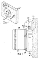
- Fig 1 illustrates schematically how an arrangement 1 according to the invention may be located inside a building 2, such as in a cellar thereof, in a closet or the like.
- the arrangement is configured to transport earth gases emanating from the soil 3 from a space 4 under the building to the atmosphere 5 and has an airtight housing 6 having an inlet opening 7 configured to be connected to a pipe 8 in fluid communication with said space 4 and an outlet opening 9 configured to be connected to a pipe 10 for exhausting said earth gases to the atmosphere.
- a filter 11 may be arranged upstream of the housing 6 for collecting particles drawn from said space 4 through the air flow for preventing them from entering the housing and causing disturbances of the function of the fan unit arranged therein.
- Fig 2 illustrates the arrangement, and it is shown how an electronic control unit 12 is connected to the interior of the housing 6 for controlling the operation of a fan unit located therein and described further below and possibly also for monitoring the function of the fan unit by detecting parameters relating thereto, such as the number of revolutions of an impeller of the fan unit.
- a connector 13 for connecting the arrangement to an electric power supply and an on/off-switch are also visible.
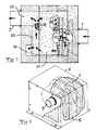
- Fig 3 illustrates the appearance of a block 15 of a compressible material designed to fill the housing 6, and opposite openings 16, 17 for connection to said housing inlet opening 7 and outlet opening 9, respectively, are shown. It appears that this block is formed by a number of superimposed parallelepipedic layers 18 of compressible material having the shape of a rectangular parallelepiped and provided with different cut-outs for together forming recesses inside said block for receiving a fan unit and members configured to define a flow path for gases from said housing inlet to a fan casing inlet and from a fan casing outlet to the housing outlet, which will be described further below.
- the compressible material is porous and here a foam material with a high density for being a foam material, namely of about 100 kg/m 3 .
- Said layers 18 are here made by the material REGENOCELL TM constituted by recycled porous fibrous material pressed together. This results in a compressible material having a good mechanical stability.
- the material will also be easy to cut for obtaining for example recesses therein and it will have a high sound absorbing capacity. In addition, it will be flame-retardant.
- Fig 4 illustrates the appearance of the layer 18' of said block 15 to be arranged next to the inlet opening of the housing, and it appears that this layer is provided with said opening 16.
- This layer 18' has also a recess 19 designed to receive a bottom surface of a fan casing 20 of a fan unit 21 shown in Fig 5 .
- the layer 18' has also a cut-out 22 designed to receive a projection 23 on said fan casing 20 for assisting said block to floatingly arrange said fan unit 21 inside the housing.
- Said fan unit 21 has on one hand said fan casing 20 connected by an inlet 24 to the housing inlet 7 and by an outlet 25 to the housing outlet 9 and enclosing an impeller 26 and on the other a motor 27 received in a motor casing 28 configured rotate said impeller for generating a gas flow through the housing from the inlet to the outlet thereof and by that transporting gases from the space 4 to the atmosphere 5. It is illustrated how the motor casing 28 is attached to the fan casing 20 by resilient connecting members 29 suspending the motor 27, here an EC-motor of high efficiency, elastically with respect to the fan casing for absorbing vibrations resulting from the operation of the motor.
- Figs 6 and 7 illustrate how cut-outs are made in said compressible material block layers for receiving the fan casing and the motor casing 28 of the fan unit 21 and other cut-outs made for defining said flow path for gases from the housing inlet to the fan casing inlet and from the fan casing outlet to the housing outlet.
- the flow path of gases from the fan casing outlet 25 to the housing outlet 9 will now be described while making reference to Figs 5-7 .
- Cut-outs 30 are made in said compressible material block layers for defining a first channel portion 31 extending from the fan casing outlet 25 substantially perpendicularly thereto and to the housing wall provided with a housing inlet. Said first channel portion 31 emerges into a second channel portion 32 realized through further cut-outs and connected to the first channel portion through a first bend 33 of 90°. The presence of this second channel portion 32 results in a prolongation of the flow path from the fan casing outlet to the housing outlet resulting in an efficient suppressing of noise from exhaust air from the fan.
- the second channel portion ends in a second bend 34 of 90° connecting it to a third channel portion 35 ending at the housing outlet 9 and extending substantially in parallel with and in the same direction as the first channel portion 31.
- the member configured to defined a flow path from the outlet of the fan casing to the outlet of the housing formed by the cut-outs resulting in the channel portions 31, 33 and 35 has a first opening 36 in fluid communication with the interior of the motor casing 28 for diverting a portion of exhaust gases from the fan casing into one end 37 of the motor casing and upstream of said first opening a second opening 38 in fluid communication with another end 39 of the motor casing for receiving gases having passed the motor for cooling of the motor. Accordingly, a minor part of the gases exhausted by the fan towards the housing outlet is by this recirculated for obtaining appropriate cooling of the motor.
Landscapes
- Engineering & Computer Science (AREA)
- Life Sciences & Earth Sciences (AREA)
- General Life Sciences & Earth Sciences (AREA)
- Toxicology (AREA)
- Environmental & Geological Engineering (AREA)
- Hydrology & Water Resources (AREA)
- Health & Medical Sciences (AREA)
- Mining & Mineral Resources (AREA)
- Paleontology (AREA)
- Civil Engineering (AREA)
- General Engineering & Computer Science (AREA)
- Structural Engineering (AREA)
- Structures Of Non-Positive Displacement Pumps (AREA)
- Cooling Or The Like Of Electrical Apparatus (AREA)
Claims (14)
- Anordnung zum Transport von aus dem Erdreich (3) ausströmenden Erdgasen von einem räumlichen Bereich (4) unter einem Gebäude (2) in die Atmosphäre, wobei die Anordnung umfasst :• ein luftdichtes Gehäuse (6) mit einer Einlaseöffnung (7), welche für die Verbindung mit einem Rohr (8) in Fluidkommunikation mit dem räumlichen Bereich konfiguriert ist, und mit einer Auslassöffnung (9), welche für die Verbindung mit einem Rohr (10) zum Abführen der Erdgase in die Atmosphäre konfiguriert ist, und• eine Lüftereinheit (21), die im Inneren des Gehäuses angeordnet ist und die einerseits ein Lüftergehäuse (20), welches über einen Einlass (24) mit dem erwähnten Gehäuseeinlass und über einen Auslass (25) mit dem erwähnten Gehäuseauslass verbunden ist und welches ein Lüfterrad umgibt, und andererseits einen Motor (27) aufweist, welcher dazu konfiguriert ist, das Lüfterrad rotieren zu lassen, um einen Gasstrom durch das luftdichte Gehäuse von dessen Einlass bis zu dessen Auslass zu erzeugen, und somit Gase aus dem räumlichen Bereich in die Atmosphäre zu transportieren, wobeidas Gehäuse (6) mit einem Block (15) gefüllt ist, der aus komprimierbarem Material, mit Außenabmessungen entsprechend den inneren Abmessungen des Gehäuses, hergestellt ist und der mit Aussparungen (19) für die Lüftereinheit sowie mit Elementen versehen ist, die dazu konfiguriert sind, einen Strömungsweg für die Gase, von dem Gehäuseeinlass zu dem Einlass des Lüftergehäuses und von dem Auslass des Lüftergehäuses zu dem Gehäuseauslass, zu begrenzen, dadurch gekennzeichnet, dass die zur Begrenzung des Strömungeweges konfigurierten Elemente durch in dem komprimierbaren Materialblock (15) vorgesehene Ausschnitte (16, 17, 30) ausgeformt sind.
- Anordnung nach Anspruch 1, dadurch gekennzeichnet, dass das Element, welches zur Begrenzung eines Strömungsweges vom Lüftergehäuseauslass (25) bis zum Gehluseauslass (9) konfiguriert ist, einen Kanalteil (31, 32, 35) umfasst, welcher zur Dämpfung von Lärm ausgelegt ist.
- Anordnung nach Anspruch 2, dadurch gekennzeichnet, dass der Lüftergehäuseauslass (25) und der Gehäuseauslass (9) nicht miteinander fluchtend, und zueinander versetzt, angeordnet sind, um den besagten Kanalteil zu verlängern.
- Anordnung nach Anspruch 2 oder 3, dadurch gekennzeichnet, dass die verlängerung des Kanalteils wenigstens eine, die Richtung des Luftstromes ändernde Krümmung (33, 34) von mehr als 70° aufweist.
- Anordnung nach Anspruch 4, dadurch gekennzeichnet, dass der Kanalteil wenigstens zwei solcher Krümmungen (33, 34) aufweist und dass sich ein stromabwärts der beiden Krümmungen gelegener Kanalteil (35) vorzugsweise im Wesentlichen parallel zu und in der gleichen Richtung wie ein stromaufwärts der beiden Krümmungen gelegener Kanalteil (31) erstreckt.
- Anordnung nach einem oder mehreren der vorangehenden Ansprüche, dadurch gekennzeichnet, dass das komprimierbare Material eine Dichte von über 70 kg/m3, vorzugsweise 80 kg/m3 - 200 kg/m3 und besonders bevorzugt 90 kg/m3 - 150 kg/m3 aufweist.
- Anordnung nach einem oder mehreren der vorangehenden Ansprüche, dadurch gekennzeichnet, dass das komprimierbare Material porös, und insbesondere ein Schaumstoff, ist.
- Anordnung nach einem oder mehreren der vorangehenden Ansprüche, dadurch gekennzeichnet, dass der Block (15) aus komprimierbarem Material aus aufeinander angeordneten parallelepipedförmigen Schichten (18) aus komprimierbarem Material geformt ist, welche die Form eines rechtwinkligen Parallelepipeds haben und mit unterschiedlichen Ausschnitten versehen sind, um zusammen die Aussparungen zu bilden.
- Anordnung nach einem oder mehreren der vorangehenden Ansprüche, dadurch gekennzeichnet, dass die Lüftereinheit (21) schwimmend im Inneren des Gehäuses (6) angeordnet ist, und zwar durch ein daran befestigtes Mittel (23), das sich mit den Teilen (22) des komprimierbaren Materialblocks (15) in Eingriff befindet, um die Lüftereinheit in dem komprimierbaren Material eingebettet zu halten.
- Anordnung nach Anspruch 9, dadurch gekennzeichnet, dass das Eingriffsmittel der Lüftereinheit (21) wenigstens einen Fortsatz (23) umfasst und dass die besagten Teile des Blocks wenigstens einen, in dem Block vorgesehenen Ausschnitt (22) aufweisen, der zu Aufnahme des Fortsatzes bestimmt ist.
- Anordnung nach Anspruch 9 oder 10, dadurch gekennzeichnet, dass das Eingriffsmittel (23) an dem Lüftergehäuse (20) befestigt ist.
- Anordnung nach einem oder mehreren der vorangehenden Ansprüche, dadurch gekennzeichnet, dass der Motor (27) auβerhalb des Lüftergehäuses (20) angeordnet ist.
- Anordnung nach Anspruch 12, dadurch gekennzeichnet, dass der Motor (27) an dem Lüftergehäuse (20) vorzugsweise durch federnde Verbindungselemente (29) befestigt ist, welche den Motor in Bezug auf das Lüftergebäuse elastisch aufhängen.
- Anordnung nach Anspruch 12 oder Anspruch 12 und einem oder mehreren der anderen vorangehenden Ansprüche, dadurch gekennzeichnet, dass das Element, welches zur Begrenzung eines Strömungsweges von dem Auslass (25) des Lüftergehäuses (20) zu dem Auslass (9) des Gehäuses (6) konfiguriert ist, eine erste Öffnung (36) in Fluidkommunikation mit dem Inneren eines den Motor (27) umschließenden Motorgehäuses (28), für die Umlenkung eines Teils der Abgase von dem Lüftergehäuse in ein Ende (37) des Motorgehäuses, sowie stromaufwärts oder stromabwärts der ersten Öffnung eine zweite Öffnung (38) in Fluidkommunikation mit einem anderen Ende (39) des Motorgehäuses, für die Aufnahme von Gasen, die zur Kühlung des Motors an diesem vorbeigeströmt sind, aufweist.
Priority Applications (3)
| Application Number | Priority Date | Filing Date | Title |
|---|---|---|---|
| ES09165879T ES2390001T3 (es) | 2009-07-20 | 2009-07-20 | Una disposición para transportar gases |
| EP20090165879 EP2292847B1 (de) | 2009-07-20 | 2009-07-20 | Anordnung zum Transport von Gasen |
| DK09165879T DK2292847T3 (da) | 2009-07-20 | 2009-07-20 | Arrangement til transport af gasser |
Applications Claiming Priority (1)
| Application Number | Priority Date | Filing Date | Title |
|---|---|---|---|
| EP20090165879 EP2292847B1 (de) | 2009-07-20 | 2009-07-20 | Anordnung zum Transport von Gasen |
Publications (2)
| Publication Number | Publication Date |
|---|---|
| EP2292847A1 EP2292847A1 (de) | 2011-03-09 |
| EP2292847B1 true EP2292847B1 (de) | 2012-06-27 |
Family
ID=40912125
Family Applications (1)
| Application Number | Title | Priority Date | Filing Date |
|---|---|---|---|
| EP20090165879 Not-in-force EP2292847B1 (de) | 2009-07-20 | 2009-07-20 | Anordnung zum Transport von Gasen |
Country Status (3)
| Country | Link |
|---|---|
| EP (1) | EP2292847B1 (de) |
| DK (1) | DK2292847T3 (de) |
| ES (1) | ES2390001T3 (de) |
Family Cites Families (5)
| Publication number | Priority date | Publication date | Assignee | Title |
|---|---|---|---|---|
| US4988237A (en) | 1989-09-29 | 1991-01-29 | Crawshaw Geoffrey K | Soil gas reduction system |
| GB2262297B (en) * | 1991-12-13 | 1995-10-11 | Philip Hancock | Gas-venting apparatus for a building and a method for its installation |
| GB2327226A (en) * | 1997-07-11 | 1999-01-20 | Donal Higgins | Radon sump |
| SE0202340L (sv) * | 2002-07-30 | 2003-10-07 | Joergen Hallberg | Anordning för bortförsel av gas under en fastighetsgrund samt användning av anordningen |
| SE528061C2 (sv) * | 2004-07-30 | 2006-08-22 | Ct Foer Miljoe Och Energiforsk | Fläktaggregat för att avlägsna radongas och/eller andra gaser |
-
2009
- 2009-07-20 DK DK09165879T patent/DK2292847T3/da active
- 2009-07-20 EP EP20090165879 patent/EP2292847B1/de not_active Not-in-force
- 2009-07-20 ES ES09165879T patent/ES2390001T3/es active Active
Also Published As
| Publication number | Publication date |
|---|---|
| DK2292847T3 (da) | 2012-10-01 |
| ES2390001T3 (es) | 2012-11-05 |
| EP2292847A1 (de) | 2011-03-09 |
Similar Documents
| Publication | Publication Date | Title |
|---|---|---|
| US7398855B2 (en) | Compressor sound attenuation enclosure | |
| US5151018A (en) | Sound attenuation chamber | |
| JP5021036B2 (ja) | ガスタービン吸気サイレンサ | |
| US6503303B2 (en) | Enclosure for an air aspirating machine | |
| CN110285495A (zh) | 一种隔振吸音装置及空调室外机 | |
| US20080202848A1 (en) | Sound absorber for gas turbine installations | |
| Ackermann et al. | Sound absorbers of a novel membrane construction | |
| EP1303209B1 (de) | Staubsauger mit schalldämmungsmittel | |
| EP2292847B1 (de) | Anordnung zum Transport von Gasen | |
| US7762373B2 (en) | Fan noise control apparatus | |
| CN107387417B (zh) | 双层压缩机及其安装方法 | |
| JP6234189B2 (ja) | 家電製品の吸音部材の取付構造及び家電製品 | |
| CN205448067U (zh) | 压缩机组件、降噪箱、压缩机、室外机及空调器 | |
| CN101460713B (zh) | 基于吸附的气体分离系统的消音器 | |
| JP5078864B2 (ja) | 換気送風機 | |
| JP2008263134A (ja) | キャビネット | |
| CN101478909B (zh) | 吸尘器 | |
| JPH04219499A (ja) | 遠心圧縮機の騒音減衰装置用の吸音材を予め圧縮する方法 | |
| JP4295255B2 (ja) | 騒音低減装置及び電気掃除機 | |
| JP2008115807A (ja) | 携帯型機器用防音ボックス | |
| CN215566930U (zh) | 用于风机的降噪装置 | |
| CN216077749U (zh) | 楼顶风机用箱式降噪装置 | |
| CN117198256B (zh) | 消声器及制氧机 | |
| CN214196787U (zh) | 一种具有消音结构的风机 | |
| CN203756338U (zh) | 一种柴油发电机的静音箱 |
Legal Events
| Date | Code | Title | Description |
|---|---|---|---|
| PUAI | Public reference made under article 153(3) epc to a published international application that has entered the european phase |
Free format text: ORIGINAL CODE: 0009012 |
|
| AK | Designated contracting states |
Kind code of ref document: A1 Designated state(s): AT BE BG CH CY CZ DE DK EE ES FI FR GB GR HR HU IE IS IT LI LT LU LV MC MK MT NL NO PL PT RO SE SI SK SM TR |
|
| 17P | Request for examination filed |
Effective date: 20110907 |
|
| GRAP | Despatch of communication of intention to grant a patent |
Free format text: ORIGINAL CODE: EPIDOSNIGR1 |
|
| GRAS | Grant fee paid |
Free format text: ORIGINAL CODE: EPIDOSNIGR3 |
|
| GRAA | (expected) grant |
Free format text: ORIGINAL CODE: 0009210 |
|
| AK | Designated contracting states |
Kind code of ref document: B1 Designated state(s): AT BE BG CH CY CZ DE DK EE ES FI FR GB GR HR HU IE IS IT LI LT LU LV MC MK MT NL NO PL PT RO SE SI SK SM TR |
|
| REG | Reference to a national code |
Ref country code: GB Ref legal event code: FG4D |
|
| REG | Reference to a national code |
Ref country code: CH Ref legal event code: EP |
|
| REG | Reference to a national code |
Ref country code: AT Ref legal event code: REF Ref document number: 564337 Country of ref document: AT Kind code of ref document: T Effective date: 20120715 |
|
| REG | Reference to a national code |
Ref country code: IE Ref legal event code: FG4D |
|
| REG | Reference to a national code |
Ref country code: DE Ref legal event code: R096 Ref document number: 602009007844 Country of ref document: DE Effective date: 20120823 |
|
| REG | Reference to a national code |
Ref country code: DK Ref legal event code: T3 |
|
| REG | Reference to a national code |
Ref country code: SE Ref legal event code: TRGR |
|
| PG25 | Lapsed in a contracting state [announced via postgrant information from national office to epo] |
Ref country code: LT Free format text: LAPSE BECAUSE OF FAILURE TO SUBMIT A TRANSLATION OF THE DESCRIPTION OR TO PAY THE FEE WITHIN THE PRESCRIBED TIME-LIMIT Effective date: 20120627 |
|
| REG | Reference to a national code |
Ref country code: ES Ref legal event code: FG2A Ref document number: 2390001 Country of ref document: ES Kind code of ref document: T3 Effective date: 20121105 |
|
| REG | Reference to a national code |
Ref country code: NL Ref legal event code: VDEP Effective date: 20120627 |
|
| REG | Reference to a national code |
Ref country code: NO Ref legal event code: T2 Effective date: 20120627 |
|
| REG | Reference to a national code |
Ref country code: AT Ref legal event code: MK05 Ref document number: 564337 Country of ref document: AT Kind code of ref document: T Effective date: 20120627 |
|
| REG | Reference to a national code |
Ref country code: LT Ref legal event code: MG4D Effective date: 20120627 |
|
| PG25 | Lapsed in a contracting state [announced via postgrant information from national office to epo] |
Ref country code: GR Free format text: LAPSE BECAUSE OF FAILURE TO SUBMIT A TRANSLATION OF THE DESCRIPTION OR TO PAY THE FEE WITHIN THE PRESCRIBED TIME-LIMIT Effective date: 20120928 Ref country code: HR Free format text: LAPSE BECAUSE OF FAILURE TO SUBMIT A TRANSLATION OF THE DESCRIPTION OR TO PAY THE FEE WITHIN THE PRESCRIBED TIME-LIMIT Effective date: 20120627 Ref country code: SI Free format text: LAPSE BECAUSE OF FAILURE TO SUBMIT A TRANSLATION OF THE DESCRIPTION OR TO PAY THE FEE WITHIN THE PRESCRIBED TIME-LIMIT Effective date: 20120627 Ref country code: LV Free format text: LAPSE BECAUSE OF FAILURE TO SUBMIT A TRANSLATION OF THE DESCRIPTION OR TO PAY THE FEE WITHIN THE PRESCRIBED TIME-LIMIT Effective date: 20120627 |
|
| PG25 | Lapsed in a contracting state [announced via postgrant information from national office to epo] |
Ref country code: RO Free format text: LAPSE BECAUSE OF FAILURE TO SUBMIT A TRANSLATION OF THE DESCRIPTION OR TO PAY THE FEE WITHIN THE PRESCRIBED TIME-LIMIT Effective date: 20120627 Ref country code: IS Free format text: LAPSE BECAUSE OF FAILURE TO SUBMIT A TRANSLATION OF THE DESCRIPTION OR TO PAY THE FEE WITHIN THE PRESCRIBED TIME-LIMIT Effective date: 20121027 Ref country code: EE Free format text: LAPSE BECAUSE OF FAILURE TO SUBMIT A TRANSLATION OF THE DESCRIPTION OR TO PAY THE FEE WITHIN THE PRESCRIBED TIME-LIMIT Effective date: 20120627 Ref country code: CZ Free format text: LAPSE BECAUSE OF FAILURE TO SUBMIT A TRANSLATION OF THE DESCRIPTION OR TO PAY THE FEE WITHIN THE PRESCRIBED TIME-LIMIT Effective date: 20120627 Ref country code: CY Free format text: LAPSE BECAUSE OF FAILURE TO SUBMIT A TRANSLATION OF THE DESCRIPTION OR TO PAY THE FEE WITHIN THE PRESCRIBED TIME-LIMIT Effective date: 20120627 Ref country code: BE Free format text: LAPSE BECAUSE OF FAILURE TO SUBMIT A TRANSLATION OF THE DESCRIPTION OR TO PAY THE FEE WITHIN THE PRESCRIBED TIME-LIMIT Effective date: 20120627 Ref country code: SK Free format text: LAPSE BECAUSE OF FAILURE TO SUBMIT A TRANSLATION OF THE DESCRIPTION OR TO PAY THE FEE WITHIN THE PRESCRIBED TIME-LIMIT Effective date: 20120627 Ref country code: AT Free format text: LAPSE BECAUSE OF FAILURE TO SUBMIT A TRANSLATION OF THE DESCRIPTION OR TO PAY THE FEE WITHIN THE PRESCRIBED TIME-LIMIT Effective date: 20120627 |
|
| PG25 | Lapsed in a contracting state [announced via postgrant information from national office to epo] |
Ref country code: PT Free format text: LAPSE BECAUSE OF FAILURE TO SUBMIT A TRANSLATION OF THE DESCRIPTION OR TO PAY THE FEE WITHIN THE PRESCRIBED TIME-LIMIT Effective date: 20121029 Ref country code: MK Free format text: LAPSE BECAUSE OF FAILURE TO SUBMIT A TRANSLATION OF THE DESCRIPTION OR TO PAY THE FEE WITHIN THE PRESCRIBED TIME-LIMIT Effective date: 20120627 Ref country code: MC Free format text: LAPSE BECAUSE OF NON-PAYMENT OF DUE FEES Effective date: 20120731 Ref country code: PL Free format text: LAPSE BECAUSE OF FAILURE TO SUBMIT A TRANSLATION OF THE DESCRIPTION OR TO PAY THE FEE WITHIN THE PRESCRIBED TIME-LIMIT Effective date: 20120627 |
|
| PG25 | Lapsed in a contracting state [announced via postgrant information from national office to epo] |
Ref country code: NL Free format text: LAPSE BECAUSE OF FAILURE TO SUBMIT A TRANSLATION OF THE DESCRIPTION OR TO PAY THE FEE WITHIN THE PRESCRIBED TIME-LIMIT Effective date: 20120627 |
|
| PLBE | No opposition filed within time limit |
Free format text: ORIGINAL CODE: 0009261 |
|
| STAA | Information on the status of an ep patent application or granted ep patent |
Free format text: STATUS: NO OPPOSITION FILED WITHIN TIME LIMIT |
|
| REG | Reference to a national code |
Ref country code: IE Ref legal event code: MM4A |
|
| 26N | No opposition filed |
Effective date: 20130328 |
|
| REG | Reference to a national code |
Ref country code: DE Ref legal event code: R097 Ref document number: 602009007844 Country of ref document: DE Effective date: 20130328 |
|
| PG25 | Lapsed in a contracting state [announced via postgrant information from national office to epo] |
Ref country code: MT Free format text: LAPSE BECAUSE OF FAILURE TO SUBMIT A TRANSLATION OF THE DESCRIPTION OR TO PAY THE FEE WITHIN THE PRESCRIBED TIME-LIMIT Effective date: 20120627 Ref country code: IE Free format text: LAPSE BECAUSE OF NON-PAYMENT OF DUE FEES Effective date: 20120720 Ref country code: BG Free format text: LAPSE BECAUSE OF FAILURE TO SUBMIT A TRANSLATION OF THE DESCRIPTION OR TO PAY THE FEE WITHIN THE PRESCRIBED TIME-LIMIT Effective date: 20120927 |
|
| REG | Reference to a national code |
Ref country code: CH Ref legal event code: PL |
|
| PG25 | Lapsed in a contracting state [announced via postgrant information from national office to epo] |
Ref country code: TR Free format text: LAPSE BECAUSE OF FAILURE TO SUBMIT A TRANSLATION OF THE DESCRIPTION OR TO PAY THE FEE WITHIN THE PRESCRIBED TIME-LIMIT Effective date: 20120627 Ref country code: CH Free format text: LAPSE BECAUSE OF NON-PAYMENT OF DUE FEES Effective date: 20130731 Ref country code: LI Free format text: LAPSE BECAUSE OF NON-PAYMENT OF DUE FEES Effective date: 20130731 |
|
| PG25 | Lapsed in a contracting state [announced via postgrant information from national office to epo] |
Ref country code: LU Free format text: LAPSE BECAUSE OF NON-PAYMENT OF DUE FEES Effective date: 20120720 Ref country code: SM Free format text: LAPSE BECAUSE OF FAILURE TO SUBMIT A TRANSLATION OF THE DESCRIPTION OR TO PAY THE FEE WITHIN THE PRESCRIBED TIME-LIMIT Effective date: 20120627 |
|
| PG25 | Lapsed in a contracting state [announced via postgrant information from national office to epo] |
Ref country code: HU Free format text: LAPSE BECAUSE OF FAILURE TO SUBMIT A TRANSLATION OF THE DESCRIPTION OR TO PAY THE FEE WITHIN THE PRESCRIBED TIME-LIMIT Effective date: 20090720 |
|
| PGFP | Annual fee paid to national office [announced via postgrant information from national office to epo] |
Ref country code: DE Payment date: 20140724 Year of fee payment: 6 Ref country code: DK Payment date: 20140722 Year of fee payment: 6 Ref country code: FI Payment date: 20140718 Year of fee payment: 6 Ref country code: NO Payment date: 20140718 Year of fee payment: 6 |
|
| PGFP | Annual fee paid to national office [announced via postgrant information from national office to epo] |
Ref country code: FR Payment date: 20140731 Year of fee payment: 6 Ref country code: ES Payment date: 20140729 Year of fee payment: 6 Ref country code: SE Payment date: 20140721 Year of fee payment: 6 Ref country code: GB Payment date: 20140725 Year of fee payment: 6 |
|
| PGFP | Annual fee paid to national office [announced via postgrant information from national office to epo] |
Ref country code: IT Payment date: 20140722 Year of fee payment: 6 |
|
| REG | Reference to a national code |
Ref country code: DE Ref legal event code: R119 Ref document number: 602009007844 Country of ref document: DE |
|
| REG | Reference to a national code |
Ref country code: DK Ref legal event code: EBP Effective date: 20150731 |
|
| REG | Reference to a national code |
Ref country code: NO Ref legal event code: MMEP |
|
| REG | Reference to a national code |
Ref country code: SE Ref legal event code: EUG |
|
| GBPC | Gb: european patent ceased through non-payment of renewal fee |
Effective date: 20150720 |
|
| PG25 | Lapsed in a contracting state [announced via postgrant information from national office to epo] |
Ref country code: IT Free format text: LAPSE BECAUSE OF NON-PAYMENT OF DUE FEES Effective date: 20150720 Ref country code: GB Free format text: LAPSE BECAUSE OF NON-PAYMENT OF DUE FEES Effective date: 20150720 Ref country code: DE Free format text: LAPSE BECAUSE OF NON-PAYMENT OF DUE FEES Effective date: 20160202 Ref country code: NO Free format text: LAPSE BECAUSE OF NON-PAYMENT OF DUE FEES Effective date: 20150731 |
|
| REG | Reference to a national code |
Ref country code: FR Ref legal event code: ST Effective date: 20160331 |
|
| PG25 | Lapsed in a contracting state [announced via postgrant information from national office to epo] |
Ref country code: FR Free format text: LAPSE BECAUSE OF NON-PAYMENT OF DUE FEES Effective date: 20150731 Ref country code: FI Free format text: LAPSE BECAUSE OF NON-PAYMENT OF DUE FEES Effective date: 20150720 Ref country code: SE Free format text: LAPSE BECAUSE OF NON-PAYMENT OF DUE FEES Effective date: 20150721 |
|
| PG25 | Lapsed in a contracting state [announced via postgrant information from national office to epo] |
Ref country code: DK Free format text: LAPSE BECAUSE OF NON-PAYMENT OF DUE FEES Effective date: 20150731 |
|
| REG | Reference to a national code |
Ref country code: ES Ref legal event code: FD2A Effective date: 20170227 |
|
| PG25 | Lapsed in a contracting state [announced via postgrant information from national office to epo] |
Ref country code: ES Free format text: LAPSE BECAUSE OF NON-PAYMENT OF DUE FEES Effective date: 20150721 |