EP2292464A1 - Scheinwerfersystem für ein Fahrzeug - Google Patents
Scheinwerfersystem für ein Fahrzeug Download PDFInfo
- Publication number
- EP2292464A1 EP2292464A1 EP10173993A EP10173993A EP2292464A1 EP 2292464 A1 EP2292464 A1 EP 2292464A1 EP 10173993 A EP10173993 A EP 10173993A EP 10173993 A EP10173993 A EP 10173993A EP 2292464 A1 EP2292464 A1 EP 2292464A1
- Authority
- EP
- European Patent Office
- Prior art keywords
- vehicle
- light
- region
- light distribution
- target object
- Prior art date
- Legal status (The legal status is an assumption and is not a legal conclusion. Google has not performed a legal analysis and makes no representation as to the accuracy of the status listed.)
- Withdrawn
Links
Images


Classifications
-
- B—PERFORMING OPERATIONS; TRANSPORTING
- B60—VEHICLES IN GENERAL
- B60Q—ARRANGEMENT OF SIGNALLING OR LIGHTING DEVICES, THE MOUNTING OR SUPPORTING THEREOF OR CIRCUITS THEREFOR, FOR VEHICLES IN GENERAL
- B60Q1/00—Arrangement of optical signalling or lighting devices, the mounting or supporting thereof or circuits therefor
- B60Q1/02—Arrangement of optical signalling or lighting devices, the mounting or supporting thereof or circuits therefor the devices being primarily intended to illuminate the way ahead or to illuminate other areas of way or environments
- B60Q1/04—Arrangement of optical signalling or lighting devices, the mounting or supporting thereof or circuits therefor the devices being primarily intended to illuminate the way ahead or to illuminate other areas of way or environments the devices being headlights
- B60Q1/14—Arrangement of optical signalling or lighting devices, the mounting or supporting thereof or circuits therefor the devices being primarily intended to illuminate the way ahead or to illuminate other areas of way or environments the devices being headlights having dimming means
- B60Q1/1415—Dimming circuits
- B60Q1/1423—Automatic dimming circuits, i.e. switching between high beam and low beam due to change of ambient light or light level in road traffic
-
- F—MECHANICAL ENGINEERING; LIGHTING; HEATING; WEAPONS; BLASTING
- F21—LIGHTING
- F21S—NON-PORTABLE LIGHTING DEVICES; SYSTEMS THEREOF; VEHICLE LIGHTING DEVICES SPECIALLY ADAPTED FOR VEHICLE EXTERIORS
- F21S41/00—Illuminating devices specially adapted for vehicle exteriors, e.g. headlamps
- F21S41/10—Illuminating devices specially adapted for vehicle exteriors, e.g. headlamps characterised by the light source
- F21S41/14—Illuminating devices specially adapted for vehicle exteriors, e.g. headlamps characterised by the light source characterised by the type of light source
- F21S41/17—Discharge light sources
-
- F—MECHANICAL ENGINEERING; LIGHTING; HEATING; WEAPONS; BLASTING
- F21—LIGHTING
- F21S—NON-PORTABLE LIGHTING DEVICES; SYSTEMS THEREOF; VEHICLE LIGHTING DEVICES SPECIALLY ADAPTED FOR VEHICLE EXTERIORS
- F21S41/00—Illuminating devices specially adapted for vehicle exteriors, e.g. headlamps
- F21S41/60—Illuminating devices specially adapted for vehicle exteriors, e.g. headlamps characterised by a variable light distribution
- F21S41/68—Illuminating devices specially adapted for vehicle exteriors, e.g. headlamps characterised by a variable light distribution by acting on screens
- F21S41/683—Illuminating devices specially adapted for vehicle exteriors, e.g. headlamps characterised by a variable light distribution by acting on screens by moving screens
- F21S41/698—Shaft-shaped screens rotating along its longitudinal axis
-
- B—PERFORMING OPERATIONS; TRANSPORTING
- B60—VEHICLES IN GENERAL
- B60Q—ARRANGEMENT OF SIGNALLING OR LIGHTING DEVICES, THE MOUNTING OR SUPPORTING THEREOF OR CIRCUITS THEREFOR, FOR VEHICLES IN GENERAL
- B60Q2300/00—Indexing codes for automatically adjustable headlamps or automatically dimmable headlamps
- B60Q2300/05—Special features for controlling or switching of the light beam
- B60Q2300/056—Special anti-blinding beams, e.g. a standard beam is chopped or moved in order not to blind
-
- B—PERFORMING OPERATIONS; TRANSPORTING
- B60—VEHICLES IN GENERAL
- B60Q—ARRANGEMENT OF SIGNALLING OR LIGHTING DEVICES, THE MOUNTING OR SUPPORTING THEREOF OR CIRCUITS THEREFOR, FOR VEHICLES IN GENERAL
- B60Q2300/00—Indexing codes for automatically adjustable headlamps or automatically dimmable headlamps
- B60Q2300/40—Indexing codes relating to other road users or special conditions
- B60Q2300/42—Indexing codes relating to other road users or special conditions oncoming vehicle
-
- B—PERFORMING OPERATIONS; TRANSPORTING
- B60—VEHICLES IN GENERAL
- B60Q—ARRANGEMENT OF SIGNALLING OR LIGHTING DEVICES, THE MOUNTING OR SUPPORTING THEREOF OR CIRCUITS THEREFOR, FOR VEHICLES IN GENERAL
- B60Q2300/00—Indexing codes for automatically adjustable headlamps or automatically dimmable headlamps
- B60Q2300/40—Indexing codes relating to other road users or special conditions
- B60Q2300/45—Special conditions, e.g. pedestrians, road signs or potential dangers
Definitions
- the present invention relates to a vehicle headlight system, and more particularly, to a vehicle headlight system that automatically blocks light in at least a part of an irradiation region in order to prevent glare while a vehicle travels.
- JP-A-2008-37240 discloses a system that forms high beam irradiation regions that can be separately irradiated by a plurality of high beam units, and acquires images of the front side of a vehicle by a CCD camera or the like, and detects an object, such as an oncoming vehicle, that should not be irradiated. Further, glare is not directed at the object that should not be irradiated by turning off a high beam unit, which would irradiate the region where the object that should not be irradiated is located.
- a vehicle headlight system including a lamp unit configured to selectively illuminate a front region in front of a vehicle with one of a plurality of types of light distribution patterns; a capturing unit configured to capture image frame data of the front region, the image frame data including the one of the plurality of types of light distribution patterns; a light blocking storage unit configured to store light blocking information in which light blocking regions of the plurality of types of light distribution patterns are associated with the types of the light distribution patterns; an extraction processor configured to extract a target object in the image frame data; and a controller configured to select one of the plurality of types of the light distribution patterns, wherein when the extraction processor extracts the target object in the image frame data, the controller selects one of the plurality of types of light distribution patterns that is capable of suppressing glare directed to the target object, and wherein the extraction processor sets a region of interest in a light blocking region of the selected light distribution pattern on the image frame data, based on the light blocking information, thereby improving
- the target object includes, for example, a pedestrian or a bicycle in addition to a forward located vehicle such as an oncoming vehicle or a forward traveling vehicle.
- the controller selects a light distribution pattern including a light blocking region that does not direct glare at the target object. Since the light blocking storage unit stores the types of the light distribution patterns and the light blocking information corresponding to light blocking regions of the light distribution patterns, the extraction processor specifies a light blocking region based on the current light distribution pattern and sets a region of interest, which corresponds to the light blocking region, on the image frame data. Further, the extraction performance for extracting the target object in the region of interest is improved. In this case, it is preferable that the extraction performance be equal to or close to the extraction performance in the light unblocking region.
- the extraction processor may also perform brightness adjustment, which increases the brightness of the region of interest, in order to improve the extraction performance of extracting the target object. According to this aspect, it may be possible to easily detect the target object in the light blocking region.
- the vehicle headlight system may further include a notification unit that notifies a driver of the fact that the target object exists in the light blocking region, when the target object exists in the light blocking region.
- the notification unit notifies a driver of, for example, the existence of the target object with a voice or an image.
- the notification unit may notify a driver of whether the target object is, specifically, an oncoming vehicle, a forward traveling vehicle, or a pedestrian, by analyzing the target object.
- the notification unit may merely notify a driver of the existence of the object. According to this aspect, even though the light blocking region is changed, the state of the light blocking region is notified to a driver. Accordingly, even when a field of view is changed due to light blocking, it may be possible to suppress discomfort that may be felt by a driver due to the change of the field of view.
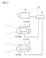
- Fig. 1 is a conceptual diagram showing the structure of a vehicle headlight system 100 according to an embodiment of the invention.
- the vehicle headlight system 100 mainly includes a capturing unit 102, a vehicle controller 302, and headlight units 210.
- the headlight units 210 are formed of a left headlight unit 210L and a right headlight unit 210R that are respectively disposed at end portions of a vehicle in a vehicle width direction.
- Each of the headlight units 210L and 210R of this embodiment is a so-called adaptive front-lighting system (AFS) that forms a low beam light distribution pattern by blocking a part of a beam irradiated from, for example, one light source and forms a high beam light distribution pattern when not blocking the beam.
- AFS adaptive front-lighting system
- Each of the headlight units 210L and 210R includes low and high beam light distribution patterns for left-side travel that are used in a region where vehicles or pedestrians keep to the left according to a traffic regulation.
- a side high light distribution pattern which is formed by blocking light on a traveling lane side or an opposite lane side of the high beam light distribution pattern
- a concave light distribution pattern which is formed by blocking light at the middle portion of the high beam light distribution pattern, or the like may also be formed.
- the shapes of light distribution patterns formed by a lamp unit 10, which is used in a region where vehicles or pedestrians keep to the right according to a traffic regulation are symmetrical with those of the light distribution patterns for left-side travel.
- the capturing unit 102 may be formed of, for example, a CCD camera that acquires image frame data of the front side of the vehicle. It is preferable that the capturing unit 102 be fixed at a position where the capturing unit can look ahead of the vehicle and is in a sweep range of a windshield wiper. For example, the capturing unit could be fixed to a bracket provided on the back side of a rear-view mirror (inside the front glass).
- a capturing range of the capturing unit 102 includes at least a traveling lane where a vehicle travels, an opposite lane, and a sidewalk on the front region of a vehicle, and preferably includes an irradiation region of the high beam light distribution pattern.
- the capturing range includes a traveling lane and at least left and right lanes of the traveling lane and preferably includes an irradiation region of the high beam light distribution pattern.
- the capturing unit has a swivel function, it is preferable that a capturing range of the capturing unit be equal to or wider than a range obtained by adding a swivel angle to the above-mentioned capturing range.
- the vehicle controller 302 detects a target object, such as a forward located vehicle (such as an oncoming vehicle or a forward traveling vehicle, which exists on the front side of the vehicle), a pedestrian, or a bicycle, based on the image frame data; and determines whether the target object is a target object that receives glare from a high beam light distribution pattern irradiated by the vehicle.
- the vehicle controller 302 provides information, which is based on the result of the determination, to irradiation controllers 228L and 228R of the headlight units 210L and 210R.
- Each of the irradiation controllers 228L and 228R performs a control for selecting and forming a light distribution pattern suitable for the circumstances around the vehicle, that is, a light distribution pattern that does not direct glare or a light distribution pattern that improves driver's field of view, based on the information that is provided from the vehicle controller 302.
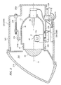
- Fig. 2 is a schematic cross-sectional view showing the internal structure of the headlight unit 210.
- the headlight unit 210 is an adaptive front-lighting system (AFS) that is disposed at each of the left and right portions of the vehicle in the vehicle width direction, and the structure of the headlight unit disposed on the right portion is substantially the same as that of the headlight unit disposed on the left portion. Accordingly, the structure of the headlight unit 210R disposed on the right portion of the vehicle will be described below on behalf of the structure of the headlight units.
- the headlight unit 210R includes a lamp body 212 and a transparent cover 214.
- the lamp body 212 includes an opening that is formed at a front portion of the lamp body on the front side of the vehicle, and a detachable cover 212a that is provided at a rear portion of the lamp body and is separated at the time of the replacement of a bulb 14. Further, the transparent cover 214 is connected to the opening formed at the front portion of the lamp body 212, so that a lamp chamber 216 is formed. A lamp unit 10, which irradiates light to the front side of the vehicle, is received in the lamp chamber 216. A lamp bracket 218, which includes a pivot mechanism 218a to serve as a swiveling center of the lamp unit 10, is formed at a part of the lamp unit 10.
- the lamp bracket 218 is connected to aiming adjustment screws 220 that are rotatably supported on the wall surface of the lamp body 212. Accordingly, the lamp unit 10 is supported at a predetermined position in the lamp chamber 216 while being tiltable by the adjustment of the aiming adjustment screws 220.
- a rotating shaft 222a of a swivel actuator 222 (which forms an adaptive front-lighting system (AFS) for a curved road to illuminates in a traveling direction while a vehicle travels on a curved road) is fixed to the lower surface of the lamp unit 10.
- the swivel actuator 222 makes the lamp unit 10 swivel about the pivot mechanism 218a in the traveling direction based on the steering angle data provided from the vehicle, the shape data of a traveling road provided from a navigation system, and a relative positional relationship between the vehicle and a forward located vehicle.
- the swivel actuator 222 may be formed of, for example, a stepping motor.
- a mechanism including the swivel actuator 222 functions as an optical axis swivel mechanism that makes the optical axis swivel in the vehicle width direction. Meanwhile, if a swivel angle has a fixed value, a solenoid or the like may be used as the swivel actuator 222.
- the swivel actuator 222 is fixed to a unit bracket 224.
- the leveling actuator 226 is formed of a motor or the like that pushes and pulls a rod 226a in directions of arrows M and N. If the rod 226a is pushed in the direction of the arrow M, the lamp unit 10 swivels about the pivot mechanism 218a so as to be in a backward inclined posture. In contrast, if the rod 226a is pulled in the direction of the arrow N, the lamp unit 10 swivels about the pivot mechanism 218a so as to be in a forward inclined posture.
- the lamp unit 10 When the lamp unit 10 is in the backward inclined posture, it may be possible to perform leveling adjustment for making the optical axis be directed to the upper side. Further, when the lamp unit 10 is in the forward inclined posture, it may be possible to perform leveling adjustment for making the optical axis be directed to the lower side. It may be possible to adjust the optical axis in accordance with the posture of the vehicle by performing the leveling adjustment as described above. As a result, it may be possible to adjust the range of light, which is irradiated toward the front side by the headlight unit 210, to an optimum distance. Meanwhile, the mechanism including the leveling actuator 226 may be referred to as an optical axis swivel mechanism.
- the leveling adjustment may be performed in accordance with the posture of a vehicle that is traveling. For example, if a vehicle accelerates while traveling, the posture of the vehicle becomes the backward inclined posture. In contrast, if a vehicle decelerates while traveling, the posture of the vehicle becomes the forward inclined posture. Accordingly, the irradiation direction of the headlight unit 210 also changes in a vertical direction in accordance with the posture of the vehicle, and forward irradiation distance increases or decreases. Further, it may be possible to optimally adjust the range of light, which is irradiated toward the front side, even while the vehicle is traveling by performing the leveling adjustment of the lamp unit 10 in real time based on the posture of the vehicle. This may be referred to as "auto-leveling".
- an irradiation controller 228R is disposed to control the headlight unit 210R.
- the irradiation controller 228R also controls the swivel actuator 222, the leveling actuator 226, and the like.
- the headlight unit 210L may include a dedicated irradiation controller 228L.
- the irradiation controller 228R provided in the headlight unit 210R may collectively control the respective actuators of the headlight units 210R and 210L or collectively control the formation of the light distribution patterns.
- the lamp unit 10 may include an aiming adjustment mechanism.
- an aiming pivot mechanism which functions as a swiveling center during aiming adjustment, is disposed at a connection portion between the unit bracket 224 and the rod 226a of the leveling actuator 226.
- a pair of the above-mentioned aiming adjustment screws 220 is disposed at the lamp bracket 218 at an interval in the vehicle width direction.
- the lamp unit 10 swivels about the aiming pivot mechanism so as to be in the forward inclined posture. Accordingly, an optical axis is adjusted so as to be directed to the lower side.
- the lamp unit 10 swivels about the aiming pivot mechanism so as to be in the backward inclined posture. Accordingly, an optical axis is adjusted so as to be directed to the upper side. Furthermore, when the aiming adjustment screw 220, which is disposed on the left side in the vehicle width direction, is rotated in the counterclockwise direction, the lamp unit 10 swivels about the aiming pivot mechanism so as to be positioned in a right swivel posture. Accordingly, an optical axis is adjusted so as to be directed to the right side.
- the lamp unit 10 swivels about the aiming pivot mechanism to be positioned in a left swivel posture. Accordingly, an optical axis is adjusted so as to be directed to the left side.
- This aiming adjustment is performed at the time of the shipment of vehicles, the detection of vehicles, or the replacement of the headlight unit 210. Further, the headlight unit 210 is adjusted to a posture that is prescribed in design, and the formation of the light distribution pattern of this embodiment is controlled based on this posture.
- the lamp unit 10 includes a shade mechanism 18 including a rotary shade 12 (which may also be referred to as a variable shade), a bulb 14 as a light source, a lamp housing 17 that supports the reflector 16 on an inner wall thereof, and a projection lens 20.
- a shade mechanism 18 including a rotary shade 12 (which may also be referred to as a variable shade), a bulb 14 as a light source, a lamp housing 17 that supports the reflector 16 on an inner wall thereof, and a projection lens 20.
- a rotary shade 12 which may also be referred to as a variable shade
- a bulb 14 as a light source
- a lamp housing 17 that supports the reflector 16 on an inner wall thereof
- a projection lens 20 for example, an incandescent bulb, a halogen lamp, a discharge bulb, an LED, or the like may be used as the bulb 14.
- the bulb 14 formed of a halogen lamp is shown as an example.
- the reflector 16 reflects light that is emitted from the bulb
- Fig. 3 is a schematic perspective view of the rotary shade 12.
- the rotary shade 12 is a cylindrical member that is rotatable about a rotating shaft 12a.
- the rotary shade 12 includes a cutout portion 22 that is formed by cutting a part of the rotary shade in an axial direction, and holds a plurality of plate-like shade plates 24 on an outer peripheral surface 12b except for the cutout portion 22.
- the rotary shade 12 may move one of the cutout portion 22 and the shade plates 24 to a position on a rear focal plane, which includes the rear focus of the projection lens 20, in accordance with the rotation angle thereof.
- a light distribution pattern is formed so as to follow the shape of an edge portion of the shade plate 24, which is positioned on the optical axis O, in accordance with the rotation angle of the rotary shade 12.
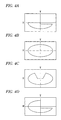
- a low beam light distribution pattern shown in Fig. 4A or a light distribution pattern that partially has the characteristics of a low beam light distribution pattern.
- a high beam light distribution pattern shown in Fig. 4B .
- a concave light distribution pattern shown in Fig. 4c and a side high light distribution pattern which is shown in Fig. 4D and partially has the characteristics of a high beam light distribution pattern, are formed according to the shape of the shade plate 24.
- the rotary shade 12 may be rotated by the driving of, for example, a motor. Accordingly, the rotary shade moves the cutout portion 22 or the shade plates 24, which are used to form a desired light distribution pattern, around the optical axis O by controlling the rotation angle of the motor. Meanwhile, the cutout portion 22 formed on the outer peripheral surface 12b of the rotary shade 12 may be omitted so that the rotary shade 12 has only a function of blocking light. Further, in order to form a high beam light distribution pattern, the rotary shade 12 may be made to retreat from the position of the optical axis O by the driving of, for example, a solenoid or the like.
- a low beam light distribution pattern or a light distribution pattern similar to the low beam light distribution pattern is fixed even though, for example, a motor for rotating the rotary shade 12 fails. That is, it may be possible to reliably avoid the rotary shade 12 being fixed at a posture where a high beam light distribution pattern is formed, so that a fail-safe function is achieved.
- the projection lens 20 is disposed on the optical axis O extending in the longitudinal direction of the vehicle, and the bulb 14 is disposed on the rear side of a rear focal plane of the projection lens 20.
- the projection lens 20 is a plano-convex aspheric lens of which the front surface is a convex surface and the rear surface is a flat surface.
- the projection lens projects, as an inverted image, a light source image formed on the rear focal plane onto a virtual vertical screen, which is formed on the front side of the headlight unit 210, as an inverted image.
- Fig. 5 is a functional block diagram illustrating the entire vehicle headlight system 100. That is, Fig. 5 is a diagram illustrating an operational interaction between the irradiation controllers 228L and 228R of the headlight units 210L and 210R having the above-mentioned structure and the vehicle controller 302 provided in the vehicle 300. Meanwhile, since the structure of the headlight unit 210L is basically the same as that of the headlight unit 210R as described above, only the headlight unit 210R will be described and the description of the headlight unit 210L will be omitted. Meanwhile, when the left and right headlight units 210L and 210R do not need to be particularly distinguished from each other in the description, suffixes "L" and "R" may be omitted.
- the vehicle controller 302 performs a control on the vehicle based on the information sent from various sensors, provides information, which is obtained from the vehicle, to the irradiation controllers 228, and selects light distribution patterns of the headlight units 210 by the irradiation controllers 228.
- the irradiation controller 228R of the headlight unit 210R controls the turning-on/off of the bulb 14 by controlling a power circuit 230 based on the information obtained from the vehicle controller 302 mounted on the vehicle 300. Furthermore, the irradiation controller 228R controls a variable shade controller 232, a swivel controller 234, and a leveling controller 236 based on the information obtained from the vehicle controller 302.
- the variable shade controller 232 moves a desired shade plate 24 or the cutout portion 22 around the optical axis O by controlling the driving of a motor 238 that is connected to the rotating shaft 12a of the rotary shade 12 through a gear mechanism. Meanwhile, rotation information, which represents the rotation state of the rotary shade 12 and which is obtained from a detection sensor such as an encoder provided on the motor 238 or the rotary shade 12, is provided to the variable shade controller 232, and accurate rotation control is achieved by feedback control.
- the swivel controller 234 adjusts the optical axis of the lamp unit 10 in the vehicle width direction by controlling the swivel actuator 222. For example, when a vehicle travels on a curved road or turns right or left, the swivel controller directs the optical axis of the lamp unit 10 to the traveling direction where the vehicle is to travel. Further, the leveling controller 236 adjusts the optical axis of the lamp unit 10 in the vertical direction of the vehicle by controlling the leveling actuator 226.
- the leveling controller 236 adjusts the range of light, which is irradiated toward the front side, to an optimum distance by detecting the change in the vehicle height during the acceleration or deceleration based on the information obtained from a vehicle height sensor 316, and adjusting the posture of the lamp unit 10 in accordance with the forward or backward inclination of the vehicle posture.
- the irradiation controller 228L performs the same control on the headlight unit 210L.
- the light distribution patterns formed by the headlight units 210L and 210R may be switched in accordance with the operation of a lighting switch 304 that is performed by a driver.
- the vehicle controller 302 provides the operating state of the lighting switch 304 to the irradiation controllers 228L and 228R, and forms a desired light distribution pattern by the driving of the motors 238 with the variable shade controllers 232.
- the headlight units 210L and 210R of this embodiment may be automatically controlled so as to form optimum light distribution patterns corresponding to the circumstances around the vehicle, which are detected by various sensors, without the operation of the lighting switch 304. For example, if the vehicle controller 302 might detect that a target object, such as a forward running vehicle or an oncoming vehicle, exists on the front side of a vehicle, the irradiation controllers 228 determine that glare should be prevented by forming low beam light distribution patterns. Then, the irradiation controllers form low beam light distribution patterns.
- the irradiation controller 228 determines that the driver's field of view should be improved by forming high beam light distribution patterns where light is not blocked by the rotary shade 12. Then, the irradiation controllers form high beam light distribution patterns.
- a camera 306 such as a stereo camera is connected to the vehicle controller 302 to recognize a target object.
- the image frame data of an image captured by the camera 306 is temporarily stored in a data storage unit 308 and is subjected to predetermined image processing such as object recognition processing in an extraction processor 104, so that a target object such as a vehicle in the image frame data is extracted.
- the extraction processor 104 recognizes a vehicle or a pedestrian by determining whether data corresponding to previously stored shape data of, for example, a vehicle or a pedestrian exist in the image frame data, through pattern recognition.
- the extraction processor 104 can also recognize a vehicle by detecting headlights of an oncoming vehicle or tail lamps of a preceding vehicle. Specifically, two light spots of left and right headlights of a forward vehicle, or two light spots of left and right tail lamps make a set and are turned on and off. In this case, if the light spots are light spots of a vehicle, two light spots move while showing the same behavior. That is, if it may be possible to confirm two light spots that show the same behavior, it may be possible to assume that the two light spots are light spots of the headlights or tail lamps of a vehicle. Accordingly, it may be possible to regard the two light spots as those of the headlights or tail lamps of a forward vehicle.
- a light blocking storage unit 106 is connected to the vehicle controller 302.
- Light blocking information where the kinds of light distribution patterns correspond to light blocking regions of the light distribution patterns is stored in the light blocking storage unit 106.
- the vehicle controller 302 can acquire information about the kind of a light distribution pattern, which is currently selected, from the irradiation controller 228. Accordingly, the vehicle controller 302 can acquire information about the position of the light blocking region of the light distribution pattern, which is currently selected, by acquiring the information about the kind of the light distribution pattern, which is provided from the irradiation controller 228, and the light blocking information that is stored in the light blocking storage unit 106.
- the extraction processor 104 sets a region of interest (ROI), which corresponds to the light blocking region of the currently selected light distribution pattern, on the image frame data through the vehicle controller 302. Further, the extraction processor 104 performs a control that improves the extraction performance of extracting a target object in a region of interest. For example, the extraction processor 104 performs brightness adjustment for increasing the brightness of the region of interest. As a result, it is easy to silhouette an object in a region of interest, so that it may be possible to perform image processing such as pattern recognition. Therefore, it is easy to determine whether an object is a target object. In this case, since the extraction processor 104 increases the brightness of only the region of interest, there is no effect on the extraction of an object in a light unblocking region that is originally bright. As a result, it may be possible to extract a target object well in the light unblocking region and the light blocking region.
- ROI region of interest
- the camera 306 of the capturing unit 102 is formed of a CCD camera that has sensitivity distribution up to infrared light, and the capturing unit 102 includes an infrared radiator that irradiates infrared light to the front side of the vehicle. If a region of interest is set, the extraction processor 104 irradiates at least the region of interest with infrared light by the infrared radiator.
- the camera 306 acquires a visible light image in a portion of the light unblocking region where visible light and infrared light are reflected, and acquires an infrared light image in a portion of the light blocking region where infrared light is reflected.
- image frame data which can be acquired by the capturing unit 102, becomes a composite image that is obtained by combining the visible light image of the light unblocking region with the infrared light image of the light blocking region. Therefore, the extraction processor 104 can extract a target object by analyzing the acquired composite image together with the region of interest.
- the extraction processor 104 can efficiently extract a target object by changing the intensity of the infrared light irradiating the region of interest in accordance with the detection state of an object in the region of interest. For example, if a target object can be easily extracted even through weak irradiation of infrared light, the output of infrared light is in an energy saving mode. Accordingly, it may be possible to suppress battery consumption without the deterioration of extraction performance. Furthermore, if the irradiation intensity of infrared light is increased when a certain object seems to exist but it is difficult to determine whether the certain object is a target object, it may be possible to make an accurate determination.
- the extraction processor 104 may assume whether a vehicle extracted using the infrared light image is an oncoming vehicle of which headlights are seen or a preceding vehicle of which tail lamps are seen, by using information about whether a place where a region of interest 410 is set is on a traveling lane or an opposite lane.
- the exposure time of an image element corresponding to a bright region, which is a light unblocking region is referred to as exposure time A at the time of usual capturing.
- the exposure time of a dark region, which is a region of interest is referred to as exposure time B that is longer than the exposure time A.
- an image acquisition cycle based on the exposure time B is obtained as a whole, but an image having standard brightness is obtained in the bright region that is the light unblocking region.
- an image, which is slightly out of focus will be obtained in the dark region of interest that is the light blocking region.
- the camera 306 having the same performance as the performance of a related art camera may be used. Accordingly, it may be possible to improve extraction performance for extracting a target object without causing considerable increase in cost.
- the extraction processor 104 when the extraction processor 104 performs a control for improving extraction performance, it is preferable that the extraction performance in the light blocking region be equal to or close to the extraction performance in the light unblocking region. If the extraction performance in the light blocking region is equal to or close to the extraction performance in the light unblocking region as described above, the extraction of a target object, which is performed by the extraction processor 104, becomes substantially constant in the image frame data. Accordingly, it may be possible to stably and reliably extract a target object.
- a notification unit 108 notifies a driver of the extraction of the target object.
- the notification unit 108 may notify a driver of the existence of the target object by a voice through, for example, an in-vehicle speaker. Further, the notification unit 108 may notify a driver of the existence of the target object by displaying messages or images, which represent the existence of the target object, on an in-vehicle display or an overhead display.
- the notification which is performed by the notification unit 108, may be a simple notification that merely represents the existence of the target object in the light blocking region, and may be a notification that attracts a driver's attention by adding additional information.
- the notification unit 108 may display an image of the entire front side of the vehicle based on the image frame data acquired by the extraction processor 104, and may display a target object while specifying the light unblocking region and the light blocking region in the displayed image.
- the notification unit 108 can emphasize the existence of the target object in a region that becomes dark due to light blocking and can easily attract a driver's attention by displaying a target object existing in the light blocking region while specifying the light blocking region.
- the notification unit 108 may notify a driver of whether a target object is, specifically, an oncoming vehicle, a forward running vehicle, or a pedestrian, by analyzing the target object.
- the notification unit 108 may display the image of a vehicle or a pedestrian by using the image frame data that is obtained by the capturing unit 102, and may display a previously prepared image or mark of a vehicle or a pedestrian. Specifically, there is an advantage of attracting a driver's attention by displaying a vehicle or a pedestrian. Meanwhile, the notification unit 108 can further attract a driver's attention by making a notification using a voice and a mark.
- the image frame data includes white lines (lane marks) or signs as well as a forward vehicle, a pedestrian, and a bicycle. Accordingly, the white lines or signs may be included as target objects in the light blocking region, and the existence of the white lines or signs may be indicated to a driver.
- the detection of the white lines or signs may be used for the control of the vehicle headlight system as described in this embodiment, and may also be used for other control, such as the travel control or braking control of a vehicle, other than the control of the vehicle headlight system.
- the image frame data which is stored in the data storage unit 308, may be directly provided to the vehicle controller 302.
- a real time image may be displayed on an in-vehicle display or an overhead display, and may be used for other control other than the control of the headlight system.
- the capturing unit 102 includes the camera 306 and the data storage unit 308.
- the vehicle controller 302 may also acquire information from a vehicle height sensor 316, a vehicle speed sensor 312, a steering sensor 310 and the like that are generally mounted on the vehicle 300. Further, the vehicle controller 302 provides the information of the traveling state or the travel posture of the vehicle 300 to the irradiation controller 228.
- the irradiation controller 228 may perform a control for selecting a light distribution pattern, which is formed based on various kinds of provided information, or simply changing the light distribution pattern by changing the direction of an optical axis.
- the irradiation controller 228 may select a shade plate 24, which forms a light distribution pattern for improving the field of view in the turning direction, by controlling the rotation of the rotary shade 12. Furthermore, the irradiation controller 228 may control the swivel actuator 222 by the swivel controller 234 without changing the rotational state of the rotary shade 12. As a result, the irradiation controller may improve the field of view in the turning direction by directing the optical axis of the lamp unit 10 to the turning direction. This control mode may be referred to as a turning sensing mode.
- the vehicle controller 302 determines that a vehicle travels at a high speed based on the information obtained from the vehicle speed sensor 312, the vehicle controller 302 provides the information to the irradiation controller 228.
- the irradiation controller 228 selects a shade plate 24, which forms a low beam light distribution pattern corresponding to a highway mode where the shape of the low beam light distribution pattern is partially changed, by controlling the rotation of the rotary shade 12 based on the information.
- the same control may also be achieved by making the lamp unit 10 be in the backward inclined posture through the control of the leveling actuator 226 that is performed by the leveling controller 236.
- the automatic leveling control which is performed during the acceleration or deceleration by the above-mentioned leveling actuator 226, is a control that maintains the irradiation distance to be constant. If the height of a cutoff line is actively controlled by using this control, it may be possible to perform a control equivalent to the control for selecting a different cutoff line by rotating the rotary shade 12. This control mode may be referred to as a speed sensing mode.
- the optical axis of the lamp unit 10 may be adjusted without using the swivel actuator 222 or the leveling actuator 226.
- the vehicle controller 302 may also acquire information about the shape or form of a road, information about the installation of road signs, and the like from a navigation system 314. These kinds of information are acquired in advance and provided to the irradiation controller 228. As a result, the irradiation controller 228 may smoothly form a light distribution pattern suitable for a traveling road by controlling the leveling actuator 226, the swivel actuator 222, the motor 238, and the like. This control mode may be referred to as a navigation sensing mode.
- Fig. 6 shows an example of light blocking information that is stored in the light blocking storage unit 106.
- the light blocking information of a "left-side high light distribution pattern", a "right-side high light distribution pattern”, and a “concave light distribution pattern” are shown in Fig. 6 as an example.
- the left-side high light distribution pattern is a light distribution pattern that may be used in a region where vehicles or pedestrians keep to the left according to a traffic regulation. In the case of the left-side high light distribution pattern, light is blocked only in a region of a high beam light distribution pattern corresponding to an opposite lane.
- the left-side high light distribution pattern is a light distribution pattern that can secure the forward field of view on the traveling lane by a high beam without directing glare to oncoming vehicles.
- the right-side high light distribution pattern is a light distribution pattern that may be used in a region where vehicles or pedestrians keep to the left according to a traffic regulation. In the case of the right-side high light distribution pattern, light is blocked only in a region of a high beam light distribution pattern corresponding to a traveling lane. That is, the right-side high light distribution pattern is a light distribution pattern that can secure the forward field of view on the opposite lane by a high beam without directing glare to preceding vehicles.
- the concave light distribution pattern is a light distribution pattern effective in the case where preceding vehicles or oncoming vehicles exist far away from the vehicle.
- the concave light distribution pattern is a light distribution pattern that can improve the field of view at a region close to the vehicle or in a direction facing the road without directing glare to vehicles that exist far away from the vehicle and exist near an intersection between a horizontal line H and a vertical line V.
- the extraction processor 104 can obtain the information about the light blocking region, which corresponds to the currently selected light distribution pattern, from the light blocking storage unit 106 through the vehicle controller 302. Further, the extraction processor 104 can acquire the information about the control state of the irradiation controller 228 through the vehicle controller 302. That is, the extraction processor 104 can acquire the kind of the currently selected light distribution pattern, the swiveling state, the leveling state, and the like. Accordingly, as shown in Fig.
- the extraction processor 104 can accurately classify a light unblocking region (irradiation region) 400 and a light blocking region 402, which are formed by the headlight units 210, on the image frame data that is acquired by the capturing unit 102.
- Fig, 7A shows an example where the headlight units 210 form a "left-side high light distribution pattern". Since the headlight units 210 irradiate the light unblocking region with light as described above, the extraction processor 104 can detect a pedestrian 404, who exists on the traveling lane, as a target object on the image frame data. Meanwhile, in the case of an example shown in Fig. 7A , an oncoming vehicle 406 and a pedestrian 408 exist even in the light blocking region 402.
- the extraction processor 104 sets the region of interest 410 at a portion of the left-side high light distribution pattern, which corresponds to the light blocking region 402, with reference to the light blocking information of the light blocking storage unit 106 that is obtained through the vehicle controller 302.
- the region of interest 410 is set so as to be wider than an actual light blocking region of the left-side high light distribution pattern.
- the region of interest may be set so as to have the same size as that of the light blocking region 402 shown in Fig. 6 .
- the extraction processor 104 performs brightness adjustment to increase, for example, the brightness of the region of interest 410. As a result, it is easier to detect the oncoming vehicle 406 or the pedestrian 408 than before the brightness adjustment. In this case, since brightness adjustment is not performed in the light unblocking region 400 originally having sufficient brightness, the image of the light unblocking region 400 does not become excessively bright and white. As a result, the extraction processor 104 can easily detect a target object that exists in the light unblocking region 400 and the region of interest 410, that is, the light blocking region 402. In this case, the extraction processor 104 can accurately detect whether the oncoming vehicle 406 or the pedestrian 408 exists in the region of interest 410.
- the irradiation controller 228 can accurately determine how long the current light distribution pattern preferably continues, based on the information that is obtained from the extraction processor 104 through the vehicle controller 302. That is, it may be possible to perform a control, which makes the left-side high light distribution pattern return to an original high beam light distribution pattern, at an appropriate time. Further, the irradiation controller 228 can accurately and quickly determine which light distribution pattern is preferably formed next, based on whether the oncoming vehicle 406 or the pedestrian 408 exists in the region of interest 410. As a result, it may be possible to quickly and accurately control the formation of an optimum light distribution pattern that is based on the circumstances around the vehicle.
- the accuracy of the detection of the lane may deteriorate.
- the notification unit 108 When the extraction processor 104 detects a target object in the region of interest 410, the notification unit 108 notifies a driver of detection results with a voice or an image. Since the light blocking region 402 is not irradiated with the light of the headlight units 210, a driver may feel discomfort such as the sudden change of a field of view when the light distribution pattern, which has been used until then, is switched to a new light distribution pattern. In this case, since the headlight units 210 are not completely turned off and a region irradiated with at least a low beam light distribution pattern remains as an irradiation region, the driver can normally drive the vehicle as usual but may feel psychological discomfort.
- the notification unit 108 may notify a driver of the existence of the target object. Accordingly, it may be possible to reduce the discomfort that may be felt by a driver as described above. Further, it may be possible to attract the driver's attention regarding the target object in the light blocking region 402 by the notification. Basically, the detection of a lane is not included in the notification. However, when it is detected that a vehicle abnormally approaches a white line representing a lane, it is preferable that the approach to the white line be notified in conjunction with the detection of a lane.
- the detection of a target object such as a vehicle or a pedestrian
- the selection of a light distribution pattern is performed in the irradiation controller 228.
- the detection of a target object and the selection of a light distribution pattern may be performed by a controller provided on the vehicle 300 and it may be possible to obtain the same advantages as those of the above-mentioned embodiment.
- the irradiation controller 228 may acquire the entire detection information of various sensors and the like from the vehicle 300, and the detection of a target object or the selection of a light distribution pattern may be performed on the side of the irradiation controller 228.
- the structure of the headlight unit 210 has been shown in Fig. 2 as an example of the structure of the vehicle headlight system 100 and the functional block diagram of the vehicle headlight system has been shown in Fig. 5 .
- this embodiment may be applied to the vehicle headlight system and the same advantages may be obtained.
Landscapes
- Engineering & Computer Science (AREA)
- General Engineering & Computer Science (AREA)
- Mechanical Engineering (AREA)
- Lighting Device Outwards From Vehicle And Optical Signal (AREA)
- Traffic Control Systems (AREA)
Applications Claiming Priority (1)
| Application Number | Priority Date | Filing Date | Title |
|---|---|---|---|
| JP2009201273A JP2011051441A (ja) | 2009-09-01 | 2009-09-01 | 車両用前照灯システム |
Publications (1)
| Publication Number | Publication Date |
|---|---|
| EP2292464A1 true EP2292464A1 (de) | 2011-03-09 |
Family
ID=43244766
Family Applications (1)
| Application Number | Title | Priority Date | Filing Date |
|---|---|---|---|
| EP10173993A Withdrawn EP2292464A1 (de) | 2009-09-01 | 2010-08-25 | Scheinwerfersystem für ein Fahrzeug |
Country Status (2)
| Country | Link |
|---|---|
| EP (1) | EP2292464A1 (de) |
| JP (1) | JP2011051441A (de) |
Cited By (18)
| Publication number | Priority date | Publication date | Assignee | Title |
|---|---|---|---|---|
| US8743023B2 (en) | 2010-07-23 | 2014-06-03 | Biological Illumination, Llc | System for generating non-homogenous biologically-adjusted light and associated methods |
| EP2546567A3 (de) * | 2011-07-12 | 2014-06-11 | Koito Manufacturing Co., Ltd. | Fahrzeugscheinwerfer |
| US8901850B2 (en) | 2012-05-06 | 2014-12-02 | Lighting Science Group Corporation | Adaptive anti-glare light system and associated methods |
| USD723729S1 (en) | 2013-03-15 | 2015-03-03 | Lighting Science Group Corporation | Low bay luminaire |
| EP2597364A3 (de) * | 2011-11-25 | 2015-07-22 | SL Corporation | Vorrichtung und Verfahren zur Steuerung eines KFZ-Scheinwerfers |
| US9174067B2 (en) | 2012-10-15 | 2015-11-03 | Biological Illumination, Llc | System for treating light treatable conditions and associated methods |
| CN105539269A (zh) * | 2014-10-24 | 2016-05-04 | 福特全球技术公司 | 具有自适应光分布的车辆前灯系统 |
| US9402294B2 (en) | 2012-05-08 | 2016-07-26 | Lighting Science Group Corporation | Self-calibrating multi-directional security luminaire and associated methods |
| US9532423B2 (en) | 2010-07-23 | 2016-12-27 | Lighting Science Group Corporation | System and methods for operating a lighting device |
| US9681522B2 (en) | 2012-05-06 | 2017-06-13 | Lighting Science Group Corporation | Adaptive light system and associated methods |
| WO2017116002A1 (ko) * | 2015-12-30 | 2017-07-06 | 엘지이노텍(주) | 발광 장치, 이 장치를 포함하는 광학 모듈, 및 이 모듈을 포함하는 차량 |
| US9732926B2 (en) | 2014-08-01 | 2017-08-15 | Toyota Jidosha Kabushiki Kaisha | Illumination system for generating a boundary between a shaded area and an irradiated area |
| US9827439B2 (en) | 2010-07-23 | 2017-11-28 | Biological Illumination, Llc | System for dynamically adjusting circadian rhythm responsive to scheduled events and associated methods |
| US10118534B2 (en) | 2014-04-15 | 2018-11-06 | Toyota Jidosha Kabushiki Kaisha | Irradiation apparatus |
| CN109414978A (zh) * | 2016-05-02 | 2019-03-01 | Zkw集团有限责任公司 | 用于从机动车的驾驶员的视角改善光照度的方法 |
| JP2021138365A (ja) * | 2018-09-10 | 2021-09-16 | ルミレッズ ホールディング ベーフェー | 高速画像リフレッシュシステム |
| WO2023049645A1 (en) * | 2021-09-24 | 2023-03-30 | Tusimple, Inc. | System and method for implementing an adaptive light distribution for an autonomous vehicle |
| US11723123B2 (en) | 2018-09-10 | 2023-08-08 | Lumileds Llc | High speed image refresh system |
Families Citing this family (2)
| Publication number | Priority date | Publication date | Assignee | Title |
|---|---|---|---|---|
| JP2019182256A (ja) * | 2018-04-12 | 2019-10-24 | クラリオン株式会社 | 配光制御装置、投光システム及び配光制御方法 |
| JP7442528B2 (ja) | 2019-07-18 | 2024-03-04 | 株式会社小糸製作所 | 車両用灯具システム、車両用灯具の制御装置および車両用灯具の制御方法 |
Citations (8)
| Publication number | Priority date | Publication date | Assignee | Title |
|---|---|---|---|---|
| US20030076688A1 (en) * | 2001-10-18 | 2003-04-24 | Koito Manufacturing Co., Ltd. | Projection-type headlamp also having infrared light emitting function |
| US20060038959A1 (en) * | 2004-08-23 | 2006-02-23 | Hull Jerald A | Adaptive and interactive scene illumination |
| JP2008037240A (ja) | 2006-08-04 | 2008-02-21 | Toyota Motor Corp | 車両用ヘッドランプ |
| DE102007045645A1 (de) * | 2007-09-25 | 2008-05-15 | Daimler Ag | Verfahren zur Steuerung einer Nachtsichteinrichtung und eines Scheinwerfers eines Fahrzeugs |
| DE102006055905A1 (de) * | 2006-11-27 | 2008-05-29 | Adc Automotive Distance Control Systems Gmbh | Verfahren zur Fahrzeugumfelderkennung und Vorrichtung zur Umfelderkennung in einem Kraftfahrzeug |
| US20080158360A1 (en) * | 2006-12-28 | 2008-07-03 | Denso Corporation | Vision assist apparatus |
| US20080297374A1 (en) * | 2007-05-30 | 2008-12-04 | Toyota Jidosha Kabushiki Kaisha | Vehicle imaging system and vehicle control apparatus |
| WO2009039882A1 (de) * | 2007-09-24 | 2009-04-02 | Hella Kgaa Hueck & Co. | Projektionsscheinwerferanordnung für fahrzeuge |
-
2009
- 2009-09-01 JP JP2009201273A patent/JP2011051441A/ja active Pending
-
2010
- 2010-08-25 EP EP10173993A patent/EP2292464A1/de not_active Withdrawn
Patent Citations (8)
| Publication number | Priority date | Publication date | Assignee | Title |
|---|---|---|---|---|
| US20030076688A1 (en) * | 2001-10-18 | 2003-04-24 | Koito Manufacturing Co., Ltd. | Projection-type headlamp also having infrared light emitting function |
| US20060038959A1 (en) * | 2004-08-23 | 2006-02-23 | Hull Jerald A | Adaptive and interactive scene illumination |
| JP2008037240A (ja) | 2006-08-04 | 2008-02-21 | Toyota Motor Corp | 車両用ヘッドランプ |
| DE102006055905A1 (de) * | 2006-11-27 | 2008-05-29 | Adc Automotive Distance Control Systems Gmbh | Verfahren zur Fahrzeugumfelderkennung und Vorrichtung zur Umfelderkennung in einem Kraftfahrzeug |
| US20080158360A1 (en) * | 2006-12-28 | 2008-07-03 | Denso Corporation | Vision assist apparatus |
| US20080297374A1 (en) * | 2007-05-30 | 2008-12-04 | Toyota Jidosha Kabushiki Kaisha | Vehicle imaging system and vehicle control apparatus |
| WO2009039882A1 (de) * | 2007-09-24 | 2009-04-02 | Hella Kgaa Hueck & Co. | Projektionsscheinwerferanordnung für fahrzeuge |
| DE102007045645A1 (de) * | 2007-09-25 | 2008-05-15 | Daimler Ag | Verfahren zur Steuerung einer Nachtsichteinrichtung und eines Scheinwerfers eines Fahrzeugs |
Cited By (24)
| Publication number | Priority date | Publication date | Assignee | Title |
|---|---|---|---|---|
| US9265968B2 (en) | 2010-07-23 | 2016-02-23 | Biological Illumination, Llc | System for generating non-homogenous biologically-adjusted light and associated methods |
| US9532423B2 (en) | 2010-07-23 | 2016-12-27 | Lighting Science Group Corporation | System and methods for operating a lighting device |
| US9827439B2 (en) | 2010-07-23 | 2017-11-28 | Biological Illumination, Llc | System for dynamically adjusting circadian rhythm responsive to scheduled events and associated methods |
| US8743023B2 (en) | 2010-07-23 | 2014-06-03 | Biological Illumination, Llc | System for generating non-homogenous biologically-adjusted light and associated methods |
| EP2546567A3 (de) * | 2011-07-12 | 2014-06-11 | Koito Manufacturing Co., Ltd. | Fahrzeugscheinwerfer |
| US9446707B2 (en) | 2011-11-25 | 2016-09-20 | Sl Corporation | Apparatus and method for controlling headlamp |
| EP2597364A3 (de) * | 2011-11-25 | 2015-07-22 | SL Corporation | Vorrichtung und Verfahren zur Steuerung eines KFZ-Scheinwerfers |
| US8901850B2 (en) | 2012-05-06 | 2014-12-02 | Lighting Science Group Corporation | Adaptive anti-glare light system and associated methods |
| US9681522B2 (en) | 2012-05-06 | 2017-06-13 | Lighting Science Group Corporation | Adaptive light system and associated methods |
| US9402294B2 (en) | 2012-05-08 | 2016-07-26 | Lighting Science Group Corporation | Self-calibrating multi-directional security luminaire and associated methods |
| US9174067B2 (en) | 2012-10-15 | 2015-11-03 | Biological Illumination, Llc | System for treating light treatable conditions and associated methods |
| USD723729S1 (en) | 2013-03-15 | 2015-03-03 | Lighting Science Group Corporation | Low bay luminaire |
| US10118534B2 (en) | 2014-04-15 | 2018-11-06 | Toyota Jidosha Kabushiki Kaisha | Irradiation apparatus |
| US9732926B2 (en) | 2014-08-01 | 2017-08-15 | Toyota Jidosha Kabushiki Kaisha | Illumination system for generating a boundary between a shaded area and an irradiated area |
| CN105539269B (zh) * | 2014-10-24 | 2020-04-10 | 福特全球技术公司 | 具有自适应光分布的车辆前灯系统 |
| CN105539269A (zh) * | 2014-10-24 | 2016-05-04 | 福特全球技术公司 | 具有自适应光分布的车辆前灯系统 |
| WO2017116002A1 (ko) * | 2015-12-30 | 2017-07-06 | 엘지이노텍(주) | 발광 장치, 이 장치를 포함하는 광학 모듈, 및 이 모듈을 포함하는 차량 |
| EP3399226A4 (de) * | 2015-12-30 | 2019-01-09 | LG Innotek Co., Ltd. | Lichtemittierende vorrichtung, optisches modul mit dieser vorrichtung und fahrzeug mit diesem modul |
| US10746366B2 (en) | 2015-12-30 | 2020-08-18 | Lg Innotek Co., Ltd. | Light emitting device, optical module comprising same device, and vehicle comprising same module |
| CN109414978A (zh) * | 2016-05-02 | 2019-03-01 | Zkw集团有限责任公司 | 用于从机动车的驾驶员的视角改善光照度的方法 |
| CN109414978B (zh) * | 2016-05-02 | 2022-06-03 | Zkw集团有限责任公司 | 用于从机动车的驾驶员的视角改善光照度的方法 |
| JP2021138365A (ja) * | 2018-09-10 | 2021-09-16 | ルミレッズ ホールディング ベーフェー | 高速画像リフレッシュシステム |
| US11723123B2 (en) | 2018-09-10 | 2023-08-08 | Lumileds Llc | High speed image refresh system |
| WO2023049645A1 (en) * | 2021-09-24 | 2023-03-30 | Tusimple, Inc. | System and method for implementing an adaptive light distribution for an autonomous vehicle |
Also Published As
| Publication number | Publication date |
|---|---|
| JP2011051441A (ja) | 2011-03-17 |
Similar Documents
| Publication | Publication Date | Title |
|---|---|---|
| EP2292464A1 (de) | Scheinwerfersystem für ein Fahrzeug | |
| EP2281719B1 (de) | Steuerungssystem für Lichtverteilung für Autoscheinwerfer | |
| JP5438405B2 (ja) | 車両用前照灯装置 | |
| EP2266838B1 (de) | Fahrzeugscheinwerfervorrichtung | |
| JP5438410B2 (ja) | 車両用前照灯装置 | |
| JP5424742B2 (ja) | 車両用前照灯装置 | |
| JP5833861B2 (ja) | 車両用前照灯装置および配光制御方法 | |
| JP5372616B2 (ja) | 車両用前照灯の配光制御システム | |
| JP5546326B2 (ja) | 制御装置、車両用灯具システム、車両用灯具 | |
| EP2295291A1 (de) | Fahrzeug-Scheinwerfervorrichtung | |
| EP2399777A2 (de) | Steuervorrichtung, Fahrzeugscheinwerfer und Fahrzeugscheinwerfersystem | |
| EP2394852A2 (de) | Fahrzeugscheinwerfersystem, Steuerungsvorrichtung und Fahrzeugscheinwerfer | |
| JP2011037342A (ja) | 車両用前照灯システム | |
| JP5430282B2 (ja) | 車両用前照灯の配光制御システム | |
| JP5317871B2 (ja) | 車両用前照灯装置 | |
| JP2011037414A (ja) | 車両用前照灯システム | |
| EP2388163A2 (de) | Fahrzeugscheinwerfersystem, Steuervorrichtung und Fahrzeugscheinwerfer | |
| EP2384931A2 (de) | Steuervorrichtung, Fahrzeuglampensystem und Fahrzeuglampe | |
| EP2388164A2 (de) | Fahrzeugscheinwerfersystem, Steuervorrichtung, Fahrzeugscheinwerfer und Steuerverfahren des Fahrzeugscheinwerfers | |
| EP2384933B1 (de) | Fahrzeugscheinwerfersystem, Steuerungsvorrichtung und Fahrzeugscheinwerfer | |
| JP5636483B2 (ja) | 車両用前照灯の配光制御システム | |
| JP2011238378A (ja) | 車両用灯具システム、制御装置、および車両用灯具 | |
| JP2011131773A (ja) | 前照灯制御システム |
Legal Events
| Date | Code | Title | Description |
|---|---|---|---|
| PUAI | Public reference made under article 153(3) epc to a published international application that has entered the european phase |
Free format text: ORIGINAL CODE: 0009012 |
|
| 17P | Request for examination filed |
Effective date: 20100825 |
|
| AK | Designated contracting states |
Kind code of ref document: A1 Designated state(s): AL AT BE BG CH CY CZ DE DK EE ES FI FR GB GR HR HU IE IS IT LI LT LU LV MC MK MT NL NO PL PT RO SE SI SK SM TR |
|
| AX | Request for extension of the european patent |
Extension state: BA ME RS |
|
| 17Q | First examination report despatched |
Effective date: 20130208 |
|
| STAA | Information on the status of an ep patent application or granted ep patent |
Free format text: STATUS: THE APPLICATION IS DEEMED TO BE WITHDRAWN |
|
| 18D | Application deemed to be withdrawn |
Effective date: 20150303 |