EP2291874B1 - Rundzellenakkumulator - Google Patents
Rundzellenakkumulator Download PDFInfo
- Publication number
- EP2291874B1 EP2291874B1 EP20090772093 EP09772093A EP2291874B1 EP 2291874 B1 EP2291874 B1 EP 2291874B1 EP 20090772093 EP20090772093 EP 20090772093 EP 09772093 A EP09772093 A EP 09772093A EP 2291874 B1 EP2291874 B1 EP 2291874B1
- Authority
- EP
- European Patent Office
- Prior art keywords
- round
- dissipation
- round cells
- cells
- elements
- Prior art date
- Legal status (The legal status is an assumption and is not a legal conclusion. Google has not performed a legal analysis and makes no representation as to the accuracy of the status listed.)
- Active
Links
Images



Classifications
-
- H—ELECTRICITY
- H01—ELECTRIC ELEMENTS
- H01M—PROCESSES OR MEANS, e.g. BATTERIES, FOR THE DIRECT CONVERSION OF CHEMICAL ENERGY INTO ELECTRICAL ENERGY
- H01M10/00—Secondary cells; Manufacture thereof
- H01M10/60—Heating or cooling; Temperature control
- H01M10/61—Types of temperature control
- H01M10/613—Cooling or keeping cold
-
- H—ELECTRICITY
- H01—ELECTRIC ELEMENTS
- H01M—PROCESSES OR MEANS, e.g. BATTERIES, FOR THE DIRECT CONVERSION OF CHEMICAL ENERGY INTO ELECTRICAL ENERGY
- H01M10/00—Secondary cells; Manufacture thereof
- H01M10/60—Heating or cooling; Temperature control
- H01M10/64—Heating or cooling; Temperature control characterised by the shape of the cells
- H01M10/643—Cylindrical cells
-
- H—ELECTRICITY
- H01—ELECTRIC ELEMENTS
- H01M—PROCESSES OR MEANS, e.g. BATTERIES, FOR THE DIRECT CONVERSION OF CHEMICAL ENERGY INTO ELECTRICAL ENERGY
- H01M10/00—Secondary cells; Manufacture thereof
- H01M10/60—Heating or cooling; Temperature control
- H01M10/65—Means for temperature control structurally associated with the cells
- H01M10/651—Means for temperature control structurally associated with the cells characterised by parameters specified by a numeric value or mathematical formula, e.g. ratios, sizes or concentrations
-
- H—ELECTRICITY
- H01—ELECTRIC ELEMENTS
- H01M—PROCESSES OR MEANS, e.g. BATTERIES, FOR THE DIRECT CONVERSION OF CHEMICAL ENERGY INTO ELECTRICAL ENERGY
- H01M10/00—Secondary cells; Manufacture thereof
- H01M10/60—Heating or cooling; Temperature control
- H01M10/65—Means for temperature control structurally associated with the cells
- H01M10/653—Means for temperature control structurally associated with the cells characterised by electrically insulating or thermally conductive materials
-
- H—ELECTRICITY
- H01—ELECTRIC ELEMENTS
- H01M—PROCESSES OR MEANS, e.g. BATTERIES, FOR THE DIRECT CONVERSION OF CHEMICAL ENERGY INTO ELECTRICAL ENERGY
- H01M10/00—Secondary cells; Manufacture thereof
- H01M10/60—Heating or cooling; Temperature control
- H01M10/65—Means for temperature control structurally associated with the cells
- H01M10/655—Solid structures for heat exchange or heat conduction
- H01M10/6551—Surfaces specially adapted for heat dissipation or radiation, e.g. fins or coatings
-
- H—ELECTRICITY
- H01—ELECTRIC ELEMENTS
- H01M—PROCESSES OR MEANS, e.g. BATTERIES, FOR THE DIRECT CONVERSION OF CHEMICAL ENERGY INTO ELECTRICAL ENERGY
- H01M10/00—Secondary cells; Manufacture thereof
- H01M10/60—Heating or cooling; Temperature control
- H01M10/65—Means for temperature control structurally associated with the cells
- H01M10/655—Solid structures for heat exchange or heat conduction
- H01M10/6556—Solid parts with flow channel passages or pipes for heat exchange
- H01M10/6557—Solid parts with flow channel passages or pipes for heat exchange arranged between the cells
-
- H—ELECTRICITY
- H01—ELECTRIC ELEMENTS
- H01M—PROCESSES OR MEANS, e.g. BATTERIES, FOR THE DIRECT CONVERSION OF CHEMICAL ENERGY INTO ELECTRICAL ENERGY
- H01M50/00—Constructional details or processes of manufacture of the non-active parts of electrochemical cells other than fuel cells, e.g. hybrid cells
- H01M50/20—Mountings; Secondary casings or frames; Racks, modules or packs; Suspension devices; Shock absorbers; Transport or carrying devices; Holders
- H01M50/204—Racks, modules or packs for multiple batteries or multiple cells
- H01M50/207—Racks, modules or packs for multiple batteries or multiple cells characterised by their shape
- H01M50/213—Racks, modules or packs for multiple batteries or multiple cells characterised by their shape adapted for cells having curved cross-section, e.g. round or elliptic
-
- H—ELECTRICITY
- H01—ELECTRIC ELEMENTS
- H01M—PROCESSES OR MEANS, e.g. BATTERIES, FOR THE DIRECT CONVERSION OF CHEMICAL ENERGY INTO ELECTRICAL ENERGY
- H01M50/00—Constructional details or processes of manufacture of the non-active parts of electrochemical cells other than fuel cells, e.g. hybrid cells
- H01M50/20—Mountings; Secondary casings or frames; Racks, modules or packs; Suspension devices; Shock absorbers; Transport or carrying devices; Holders
- H01M50/233—Mountings; Secondary casings or frames; Racks, modules or packs; Suspension devices; Shock absorbers; Transport or carrying devices; Holders characterised by physical properties of casings or racks, e.g. dimensions
- H01M50/24—Mountings; Secondary casings or frames; Racks, modules or packs; Suspension devices; Shock absorbers; Transport or carrying devices; Holders characterised by physical properties of casings or racks, e.g. dimensions adapted for protecting batteries from their environment, e.g. from corrosion
-
- H—ELECTRICITY
- H01—ELECTRIC ELEMENTS
- H01M—PROCESSES OR MEANS, e.g. BATTERIES, FOR THE DIRECT CONVERSION OF CHEMICAL ENERGY INTO ELECTRICAL ENERGY
- H01M6/00—Primary cells; Manufacture thereof
- H01M6/50—Methods or arrangements for servicing or maintenance, e.g. for maintaining operating temperature
- H01M6/5038—Heating or cooling of cells or batteries
-
- H—ELECTRICITY
- H01—ELECTRIC ELEMENTS
- H01M—PROCESSES OR MEANS, e.g. BATTERIES, FOR THE DIRECT CONVERSION OF CHEMICAL ENERGY INTO ELECTRICAL ENERGY
- H01M10/00—Secondary cells; Manufacture thereof
- H01M10/60—Heating or cooling; Temperature control
- H01M10/65—Means for temperature control structurally associated with the cells
- H01M10/656—Means for temperature control structurally associated with the cells characterised by the type of heat-exchange fluid
- H01M10/6569—Fluids undergoing a liquid-gas phase change or transition, e.g. evaporation or condensation
-
- Y—GENERAL TAGGING OF NEW TECHNOLOGICAL DEVELOPMENTS; GENERAL TAGGING OF CROSS-SECTIONAL TECHNOLOGIES SPANNING OVER SEVERAL SECTIONS OF THE IPC; TECHNICAL SUBJECTS COVERED BY FORMER USPC CROSS-REFERENCE ART COLLECTIONS [XRACs] AND DIGESTS
- Y02—TECHNOLOGIES OR APPLICATIONS FOR MITIGATION OR ADAPTATION AGAINST CLIMATE CHANGE
- Y02E—REDUCTION OF GREENHOUSE GAS [GHG] EMISSIONS, RELATED TO ENERGY GENERATION, TRANSMISSION OR DISTRIBUTION
- Y02E60/00—Enabling technologies; Technologies with a potential or indirect contribution to GHG emissions mitigation
- Y02E60/10—Energy storage using batteries
-
- Y—GENERAL TAGGING OF NEW TECHNOLOGICAL DEVELOPMENTS; GENERAL TAGGING OF CROSS-SECTIONAL TECHNOLOGIES SPANNING OVER SEVERAL SECTIONS OF THE IPC; TECHNICAL SUBJECTS COVERED BY FORMER USPC CROSS-REFERENCE ART COLLECTIONS [XRACs] AND DIGESTS
- Y02—TECHNOLOGIES OR APPLICATIONS FOR MITIGATION OR ADAPTATION AGAINST CLIMATE CHANGE
- Y02P—CLIMATE CHANGE MITIGATION TECHNOLOGIES IN THE PRODUCTION OR PROCESSING OF GOODS
- Y02P70/00—Climate change mitigation technologies in the production process for final industrial or consumer products
- Y02P70/50—Manufacturing or production processes characterised by the final manufactured product
Definitions
- the invention relates to a round cell battery.
- the DE 102 23 782 B4 discloses a battery having at least one electrochemical storage cell and a cooling device, which is flowed through by a liquid cooling medium.
- the memory cells are accommodated in openings of the cooling devices and are in frictional contact, each with a curved in one direction perpendicular to the longitudinal axis of the memory cell outer surface. In the areas of non-positive contact an expansion joint is provided.
- DE 10 2007 009 315 A1 discloses a device for cooling electrical elements with conductor bodies which are in thermal contact for dissipating heat with side surfaces of the electrical elements.
- Object of the present invention is therefore to provide an improved Rundzellenakkumulator.
- thermoplastic elastomer conducts the heat from the circular cells to the diverting elements which transfer the heat to the refrigerant.
- Good thermal conduction is obtained when the thermoplastic elastomer has a thermal conductivity greater than one watt per meter and Kelvin (ie> 1 W / (mK)).
- the thermal conductivity is greater than two to three watts per meter and Kelvin (ie> 3 W / (mK)).
- thermoplastic elastomers are offered by the company Cool Polymers, Inc., USA, under the names CoolPoly ® D8102 Thermally Conductive Thermoplastics elastomer (TPE) and CoolPoly ® D8104 Thermally Conductive Thermoplastics elastomer (TPE).
- thermoplastic elastomer ensures good contact between the round cells and the diverting elements due to its rubber-elastic property. Air gaps that affect the heat conduction from the circular cells to the refrigerant are effectively avoided. In particular, it is ensured by pressing the round cells in the production of round cell battery to the diverting that the heat transfer surfaces are optimally to each other and air gaps are avoided.
- Thermoplastic elastomers with a Shore A hardness of 20 to 100 have shown good results in non-public trials.
- tubular overcoat of an electrically insulating, thermally conductive and rubber-elastic thermoplastic elastomer are provided, which the round cells are pulled.
- Ableitanceieri can be arranged on the outer sides of the overcoat.
- six Ableitance electrode are provided on each overcoat of an inner round cell, which are arranged uniformly on the outside, so in 60 ° intervals.
- An inner round cell is completely surrounded parallel to its longitudinal axis by other round cells, so it is not on the edge of Rundzellenakkumulators.
- the overdubs may be formed of the same material as the Ableitrome. In this case, the overcoat and Ableitanceieri are advantageously integrally formed.
- the round cells are received in at least one Ableitanceelement common to a group of round cells, which have adapted to the side wall surfaces of the round cells receiving contour, so that these side wall surfaces abut the inner wall of an associated Ableitance electrodes, wherein the Ableitance electrode continue have a receiving bore for receiving the rod-shaped discharge elements.
- the Ableitability electrode in the longitudinal direction of triangular cross-sections with concave sides.
- the Ableitance electrode serve in this case at the same time as a spacer between the round cells. Good heat transfer between the round cells and the Ableitance electroden is achieved when the adjacent to the circular cells inner walls of the Ableitance electrode are curved.
- the Ableitance comprise incisions, which protrude radially from the receiving bore into the Ableitbasedelement.
- the incisions improve the contact between the round cells and the Ableitance shame on the one hand and the Ableitance electroden and the Ableitmaschinen other hand, when producing the Rundzellenakkumulators.
- the cuts facilitate the assembly of the individual components and thus the production of the round cell battery.
- FIG. 1 shows a tubular cover 1 of a thermoplastic elastomer, which is electrically insulating, good thermal conductivity and (rubber) elastic.
- a side view In the upper part of the FIG. 1 is a side view and in the lower section is a plan view.
- the overcoat 1 has essentially the shell shape of a circular cylinder.
- a longitudinal axis 2 coincides with the cylinder axis.
- the Ableitor institute 3 are arranged on the outer surface of the overcoat 1, six Ableitance electrode 3 are arranged.
- the Ableitor institute 3 are arranged at regular intervals to each other, ie at angular intervals of sixty degrees.
- the Ableitance institute 3 are rod-shaped and extend from a top 4 to a bottom fifth
- the Ableitance sculpture 3 have curved recesses 6 with circular arc-shaped cross-section. These recesses 6 serve as guides for (in FIG. 1 not shown) diverting with circular cylindrical cross-sections.
- FIG. 2 shows the topcoat 1 off FIG. 1 which is pulled over a round cell 7.
- the round cell 7 is formed in a known manner, in particular has a positive electrode 8 and a negative electrode 9. Evident is also a degassing valve 10th
- the overcoat 1 sits firmly on the round cell 7.
- FIG. 3 shows a perspective view of the situation FIG. 2 .
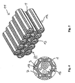
- FIGS. 4 and 5 show a plurality of arranged to a stack 11 round cells. 7 FIG. 4 shows a partial view in the direction IV.
- the stack 11 has three rows 12 each with five round cells 7.
- the rows 12 are arranged alternately offset by half a diameter of the round cells 7 perpendicular to the longitudinal direction 2 of the round cells 7 to each other. This arrangement allows a dense packing of the round cells.
- the stack 11 is not complete. It comprises only a part of all round cells 7 of a round cell battery.
- the round cells 7 each have an overcoat 1. On the outside of the overcoat 1, six Ableitance sculpture 3 are uniformly arranged. This makes sense, since in this pack of round cells 7 each round cell 7 has six direct adjacent round cells 7. This applies in any case for round cells 7, which are not at the edge of the round cell battery (inner round cell). For example, round cell 13 is an inner round cell 7.
- FIG. 4 shows diverting elements 14.
- the diverting elements 14 are each guided by three Ableitance electroden 3, wherein each of these three Ableitance electrode 3 is associated with another round cell 7.
- the diverting elements 14 have a circular cross-section. It can be seen that two adjacent round cells 7 do not touch each other directly, but are always separated from each other by two overcoats 1, in particular electrically insulated.
- FIG. 6 shows an alternative embodiment of a Ableitance institutes 15th
- the Ableitabilityelement 15 is designed rod-shaped. It has a length which corresponds approximately to the length of the round cells 7.
- the Ableitabilityelement 15 has a triangular cross section perpendicular to the longitudinal axis 2 (ie viewed in the direction of the longitudinal axis); this is in the lower section of the FIG. 6 to recognize.
- the Ableitabilityelement 15 has an adapted to the side wall surfaces of the rotary cells 7 receiving contour 16, which comprises three circular arcs.
- a receiving bore 17 is provided as a guide for a discharge element 14 with a circular cross-section.
- Three incisions 18 project radially from the receiving bore 17 into the discharge receiving element 15.
- a slot 19 in the receiving contour 16 provided.
- the diverter element 14 can be introduced into the guide via the slot 19.
- disturbing air slots are avoided when pressing the Rundzellenakkumulators.
- the slot 19 thus also serves as an expansion joint during compression.
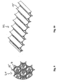
- FIG. 7 shows the round cell 7, around whose periphery adjacent to the side wall surface six Ableitance implant 15 are arranged uniformly.
- the Ableitability electrode 15 do not touch each other; This can be seen in columns 20.
- FIG. 8 shows a perspective view of FIG. 7 .
- FIG. 9 shows a partial section of a stack 21 of the circular cells 7 with the Ableitance electroden 15. It can be seen that the circular cells 7 do not touch each other due to the arrangement of the Ableitance electrode 15. Since the Ableitance electrode 15 are made of electrically insulating thermoplastic elastomer, the round cells 7 are electrically isolated from each other. The Ableitance electrode 15 are not connected to each other.
- FIG. 10 shows an intermediate layer 22, which is formed from Ableitance electroden 15.
- the intermediate layer 22 consists of a juxtaposition of Ableitance electroden 15. In each case two adjacent Ableitance electrode 15 are interconnected.
- the intermediate layer 22 is placed in the production of Rundzellenakkumulators between two adjacent rows 12 of round cells 7.
- the intermediate layer 22 offers the advantage of a simple production of the round cell battery.
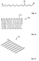
- FIG. 11 shows the diverting element 14 in plan view, that is to say in the direction of the longitudinal axis 2.
- FIG. 12 shows the discharge element 14 from FIG. 11 in side view, that is perpendicular to the longitudinal axis of the second
- FIG. 13 shows the discharge element 14 from the FIGS. 11 and 12 in a perspective view.
- FIGS. 11, 12 and 13 can be seen that the discharge element 14 extends in a zig-zag shape in three dimensions, an imaginary axis of the tubular discharge element 14 thus describes a three-dimensional serpentine curve.
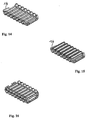
- FIGS. 14 to 19 describe a part of a mounting process of the round-cell battery.
- the discharge element 14 is inserted into a plastic part 23 ( FIG. 14 ).
- the round cells 7 provided with the overcoat 1 and the Ableitance electroden 3 are placed on the discharge element 14 such that the discharge element 14 is guided in the recesses 6 of the Ableitance electrode 3 ( FIG. 15 ).
- FIG. 19 indicates that the individual diverting elements 14 are brought together at one end 24 of the stack 11. They can be connected to a collector, not shown.
Landscapes
- Chemical & Material Sciences (AREA)
- Chemical Kinetics & Catalysis (AREA)
- Electrochemistry (AREA)
- General Chemical & Material Sciences (AREA)
- Engineering & Computer Science (AREA)
- Manufacturing & Machinery (AREA)
- Physics & Mathematics (AREA)
- Algebra (AREA)
- General Physics & Mathematics (AREA)
- Mathematical Analysis (AREA)
- Mathematical Optimization (AREA)
- Pure & Applied Mathematics (AREA)
- Secondary Cells (AREA)
- Battery Mounting, Suspending (AREA)
Description
- Die Erfindung betrifft einen Rundzellenakkumulator.
- Aus der
EP 0 917 230 B1 und derWO2006/124663 sind Akkumulatorenbatterien mit einer Temperiervorrichtung bekannt - Die
DE 102 23 782 B4 offenbart eine Batterie mit wenigstens einer elektrochemischen Speicherzelle und einer Kühleinrichtung, die von einem flüssigen Kühlmedium durchströmt ist. Die Speicherzellen werden in Öffnungen der Kühleinrichtungen aufgenommen und stehen mit jeweils eine in einer Richtung senkrecht zu der Längsachse der Speicherzelle gekrümmten Außenfläche teilweise in kraftschlüssigem Kontakt. In den Bereichen des kraftschlüssigen Kontaktes ist eine Dehnfuge vorgesehen. -
DE 10 2007 009 315 A1 offenbart eine Vorrichtung zur Kühlung elektrischer Elemente mit Leiterkörpern, die zur Ableitung von Wärme mit Seitenflächen der elektrischen Elemente im thermischen Kontakt stehen. - Bei einem elektrischen Akkumulator mit Rundzellen besteht das Problem der Wärmeableitung. Dieses Problem wird dadurch verschärft, dass der Becher der Zelle auf elektrischem Potential liegt.
- Aufgabe der vorliegenden Erfindung ist es daher, einen verbesserten Rundzellenakkumulator zu schaffen.
- Die Aufgabe wird durch einen Rundzellenakkumulator mit den Merkmalen von Anspruch 1 gelöst.
- Vorteilhafte Weiterbildungen des Rundzellenakkumulators sind in den Unteransprüchen angegeben.
- Die erfindungsgemäß ausgebildeten und angeordneten Ableitaufnahmeelemente erfüllen mehrere Funktionen:
- Erstens stellt das thermoplastische Elastomer die elektrische Isolierung zwischen den Rundzellen und den Ableitelementen sicher, die beispielsweise aus Kupfer, Aluminium oder Stahl hergestellt sind und ein geeignetes Kältemittel führen. Als Ableitelemente eignen sich besonders Strangpressteile. Geeignete Kältemittel sind beispielsweise Tetrafluorethan (R134a) und Kohlendioxid (R744).
- Zweitens leitet das thermoplastische Elastomer die Wärme aus den Rundzellen zu den Ableitelementen, die die Wärme auf das Kältemittel übertragen. Eine gute Wärmeleitung wird erhalten, wenn das thermoplastische Elastomer eine Wärmeleitfähigkeit größer als einen Watt pro Meter und Kelvin (also > 1 W/(mK)) aufweist. Vorzugsweise ist die Wärmeleitfähigkeit größer als zwei bis drei Watt pro Meter und Kelvin (also > 3 W/(mK)). Geeignete thermoplastische Elastomere werden von der Firma Cool Polymers, Inc., USA, unter den Bezeichnungen CoolPoly® D8102 Thermally Conductive Thermoplastics Elastomer (TPE) und Cool-Poly® D8104 Thermally Conductive Thermoplastics Elastomer (TPE) angeboten.
- Drittens gewährleistet das thermoplastische Elastomer durch seine gummielastische Eigenschaft einen guten Kontakt zwischen den Rundzellen und den Ableitelementen. Luftspalte, die die Wärmeleitung von den Rundzellen zu dem Kältemittel beeinträchtigen, werden wirksam vermieden. Insbesondere wird durch ein Anpressen der Rundzellen bei der Herstellung des Rundzellenakkumulators an die Ableitelemente sichergestellt, dass die Wärmeübergangsflächen optimal aufeinander liegen und Luftspalte vermieden werden. Thermoplastische Elastomere mit einer Shore A-Härte von 20 bis 100 haben in nicht-öffentlichen Versuchen gute Ergebnisse gezeigt.
- In einer Ausführungsform sind schlauchförmige Überzieher aus einem elektrisch isolierenden, wärmeleitfähigen und gummielastischen thermoplastischen Elastomer vorgesehen, die über die Rundzellen gezogen sind. An den Außenseiten der Überzieher können Ableitaufnahmeelemente angeordnet sein. Vorzugsweise sind sechs Ableitaufnahmeelemente an jedem Überzieher einer innenliegenden Rundzelle vorgesehen, die gleichmäßig an der Außenseite angeordnet sind, also in 60°-Abständen. Eine innenliegende Rundzelle ist parallel zu ihrer Längsachse vollständig von anderen Rundzellen umgeben, sie liegt also nicht am Rand des Rundzellenakkumulators. Die Überzieher können aus demselben Material wie die Ableitaufnahmeelemente gebildet sein. In diesem Fall sind die Überzieher und Ableitaufnahmeelemente zweckmäßig einstückig ausgebildet.
- In einer weiteren Ausführungsform sind die Rundzellen in mindestens einem für eine Gruppe von Rundzellen gemeinsame Ableitaufnahmeelement aufgenommen, die eine an die Seitenwand-Oberflächen der Rundzellen angepasste Aufnahmekontur haben, so dass diese Seitenwand-Oberflächen an der Innenwandung eines zugeordneten Ableitaufnahmeelementes anliegen, wobei die Ableitaufnahmeelemente weiterhin eine Aufnahmebohrung zur Aufnahme der stabförmigen Ableitelemente haben. Vorzugsweise weisen die Ableitaufnahmeelemente in Längsrichtung dreieckige Querschnitte mit konkaven Seiten auf. Die Ableitaufnahmeelemente dienen in diesem Fall zugleich als Abstandshalter zwischen den Rundzellen. Ein guter Wärmeübergang zwischen den Rundzellen und den Ableitaufnahmeelementen wird erreicht, wenn die an die Rundzellen angrenzenden Innenwandungen der Ableitaufnahmeelemente gekrümmt sind. Vorteilhaft weisen die Ableitaufnahmeelemente Einschnitte auf, die radial von der Aufnahmebohrung aus in das Ableitaufnahmeelement hineinragen. Die Einschnitte verbessern den Kontakt zwischen den Rundzellen und den Ableitaufnahmeelemente einerseits sowie den Ableitaufnahmeelementen und den Ableitelementen andererseits beim Herstellen des Rundzellenakkumulators. Zudem erleichtern die Einschnitte das Zusammenfügen der einzelnen Komponenten und damit die Herstellung des Rundzellenakkumulators.
- Die Erfindung wird nachfolgend anhand der beigefügten Zeichnungen näher beschrieben.
-
Figur 1 zeigt einen schlauchförmigen Überzieher 1 aus einem thermoplastischen Elastomer, das elektrisch isolierend, gut wärmeleitend und (gummi-)elastisch ist. Im oberen Ausschnitt derFigur 1 ist eine Seitenansicht und im unteren Ausschnitt eine Draufsicht dargestellt. - Der Überzieher 1 hat im Wesentlichen die Mantelform eines Kreiszylinders. Eine Längsachse 2 fällt mit der Zylinderachse zusammen.
- An der Außenfläche des Überziehers 1 sind sechs Ableitaufnahmeelemente 3 angeordnet. Die Ableitaufnahmeelemente 3 sind in gleichmäßigen Abständen zueinander angeordnet, also in Winkelabständen von sechzig Grad.
- Die Ableitaufnahmeelemente 3 sind stabförmig ausgebildet und erstrecken sich von einer Oberseite 4 bis zu einer Unterseite 5.
- Die Ableitaufnahmeelemente 3 weisen gekrümmte Ausnehmungen 6 mit kreisbogenförmigem Querschnitt auf. Diese Ausnehmungen 6 dienen als Führungen für (in
Figur 1 nicht dargestellte) Ableitelemente mit kreiszylinderförmigen Querschnitten. -
Figur 2 zeigt den Überzieher 1 ausFigur 1 , der über eine Rundzelle 7 gezogen ist. - Die Rundzelle 7 ist in bekannter Weise ausgebildet, weist insbesondere eine positive Elektrode 8 und eine negative Elektrode 9 auf. Zu erkennen ist auch ein Entgasungsventil 10.
- Aufgrund der Gummielastizität des Überziehers 1 sitzt der Überzieher 1 fest auf der Rundzelle 7.
-
Figur 3 zeigt eine perspektivische Ansicht der Situation ausFigur 2 . -
Figuren 4 und 5 zeigen eine Mehrzahl von zu einem Stapel 11 angeordneten Rundzellen 7.Figur 4 zeigt eine Teilansicht in Richtung IV. - Der Stapel 11 weist drei Reihen 12 mit je fünf Rundzellen 7 auf. Die Reihen 12 sind abwechselnd um einen halben Durchmesser der Rundzellen 7 senkrecht zu der Längsrichtung 2 der Rundzellen 7 zueinander versetzt angeordnet. Diese Anordnung ermöglicht eine dichte Packung der Rundzellen. Der Stapel 11 ist nicht vollständig. Er umfasst nur einen Teil aller Rundzellen 7 eines Rundzellenakkumulators.
- Die Rundzellen 7 weisen jeweils einen Überzieher 1 auf. An der Außenseite der Überzieher 1 sind gleichmäßig jeweils sechs Ableitaufnahmeelemente 3 angeordnet. Dies ist sinnvoll, da bei dieser Packung der Rundzellen 7 jede Rundzelle 7 sechs direkte benachbarte Rundzellen 7 hat. Dies gilt jedenfalls für Rundzellen 7, die nicht am Rand des Rundzellenakkumulators liegen (innere Rundzelle). Beispielsweise ist Rundzelle 13 eine innere Rundzelle 7.
-
Figur 4 zeigt Ableitelemente 14. Die Ableitelemente 14 werden jeweils von drei Ableitaufnahmeelementen 3 geführt, wobei jedes dieser drei Ableitaufnahmeelemente 3 einer anderen Rundzelle 7 zugeordnet ist. Die Ableitelemente 14 haben einen kreisförmigen Querschnitt. Es ist zu erkennen, dass sich zwei benachbarte Rundzellen 7 nicht direkt berühren, sondern immer durch zwei Überzieher 1 voneinander getrennt sind, insbesondere elektrisch isoliert. -
Figur 6 zeigt eine alternative Ausführungsform eines Ableitaufnahmeelementes 15. - Das Ableitaufnahmeelement 15 ist stabförmig ausgeführt. Es weist eine Länge auf, die etwa der Länge der Rundzellen 7 entspricht.
- Das Ableitaufnahmeelement 15 hat einen dreieckigen Querschnitt senkrecht zu der Längsachse 2 (also betrachtet in Richtung der Längsachse); dies ist im unteren Ausschnitt der
Figur 6 zu erkennen. - Das Ableitaufnahmeelement 15 hat eine an die Seitenwand-Oberflächen der Rundzellen 7 angepasste Aufnahmekontur 16, die drei Kreisbögen umfasst.
- Zentral ist eine Aufnahmebohrung 17 als Führung für ein Ableitelement 14 mit kreisförmigem Querschnitt vorgesehen. Drei Einschnitte 18 ragen radial von der Aufnahmebohrung 17 aus in das Ableitaufnahmeelement 15 hinein. Ferner ist ein Schlitz 19 in der Aufnahmekontur 16 vorgesehen. Über den Schlitz 19 lässt sich zum einen das Ableitelement 14 in die Führung einbringen. Zum anderen werden störende Luftschlitze beim Verpressen des Rundzellenakkumulators vermieden. Der Schlitz 19 dient also auch als Dehnungsfuge beim Verpressen.
-
Figur 7 zeigt die Rundzelle 7, um deren Umfang angrenzend an die Seitenwand-Oberfläche sechs Ableitaufnahmeelemente 15 gleichmäßig angeordnet sind. Die Ableitaufnahmeelemente 15 berühren sich nicht gegenseitig; dies ist an Spalten 20 zu erkennen. -
Figur 8 zeigt eine perspektivische Ansicht derFigur 7 . -
Figur 9 zeigt einen Teilschnitt eines Stapels 21 der Rundzellen 7 mit den Ableitaufnahmeelementen 15. Es ist zu erkennen, dass sich die Rundzellen 7 aufgrund der Anordnung der Ableitaufnahmeelemente 15 nicht gegenseitig berühren. Da die Ableitaufnahmeelemente 15 aus elektrisch isolierendem thermoplastischen Elastomer hergestellt sind, sind die Rundzellen 7 elektrisch voneinander isoliert. Die Ableitaufnahmeelemente 15 sind untereinander nicht verbunden. -
Figur 10 zeigt eine Zwischenlage 22, die aus Ableitaufnahmeelementen 15 gebildet ist. Die Zwischenlage 22 besteht aus einer Aneinanderreihung von Ableitaufnahmeelementen 15. Jeweils zwei benachbarte Ableitaufnahmeelemente 15 sind miteinander verbunden. Die Zwischenlage 22 wird bei der Herstellung des Rundzellenakkumulators zwischen zwei benachbarte Reihen 12 von Rundzellen 7 gelegt. Die Zwischenlage 22 bietet den Vorteil einer einfachen Herstellung des Rundzellenakkumulators. -
Figur 11 zeigt das Ableitelement 14 in Draufsicht, das heißt in Richtung der Längsachse 2. -
Figur 12 zeigt das Ableitelement 14 ausFigur 11 in Seitenansicht, das heißt senkrecht zu der Längsachse 2. -
Figur 13 zeigt das Ableitelement 14 aus denFiguren 11 und 12 in einer perspektivischen Ansicht. - Die
Figuren 11, 12 und 13 lassen erkennen, dass das Ableitelement 14 zick-zack-förmig in drei Dimensionen verläuft, eine gedachte Achse des rohrförmigen Ableitelementes 14 also eine dreidimensionale schlangenförmige Kurve beschreibt. -
Figuren 14 bis 19 beschreiben einen Teil eines Montageprozesses des Rundzellenakkumulators. - Zunächst wird das Ableitelement 14 in ein Kunststoffteil 23 eingelegt (
Figur 14 ). - Anschließend werden die mit dem Überzieher 1 und den Ableitaufnahmeelementen 3 versehenen Rundzellen 7 derart auf das Ableitelement 14 gelegt, dass das Ableitelement 14 in den Ausnehmungen 6 der Ableitaufnahmeelemente 3 geführt wird (
Figur 15 ). - Die Vorgänge aus den
Figuren 14 und 15 werden wiederholt bis ausreichend Reihen von Rundzellen 7 gebildet sind. -
Figur 19 lässt erkennen, dass die einzelnen Ableitelemente 14 an einem Ende 24 des Stapels 11 zusammengeführt werden. Sie können mit einem nicht dargestellten Sammler verbunden werden. - Über zwei gegenüberliegende Abschlussplatten 25, von denen nur eine sichtbar ist, wird der Rundzellenakkumulator verpresst. So wird eine optimale Anlage der Komponenten zur Wärmeübertragung gewährleistet.
Claims (8)
- Rundzellenakkumulator mita) einer Mehrzahl von nebeneinander angeordneten Rundzellen (7),b) mindestens einem elektrisch gegenüber den Rundzellen (7) isoliertes Ableitelement (14), das stabförmig ausgeführt und so gebogen ist, dass es zick-zack-förmig abwechselnd jeweils entlang einer Unterseite (5), einer sich daran anschließenden Seitenwand und einer Oberseite (4) der Rundzellen (7) verläuft und zur Wärmeableitung eine Gruppe von Rundzellen (7) wärmeleitend verbindet, undc) einem elektrisch isolierenden, wärmeleitfähigen und gummielastischen thermoplastischen Elastomer, das zumindest teilweise zwischen dem mindestens einen Ableitelement (14) und den Rundzellen (7) angeordnet ist, um die Ableitelemente (14) elektrisch von den Rundzellen (7) zu isolieren und Wärme von den Rundzellen (7) zu den Ableitelementen (14) abzuleiten.
- Rundzellenakkumulator nach Anspruch 1, gekennzeichnet durch schlauchförmige Überzieher (1) aus elektrisch isolierenden, wärmeleitfähigen und gummielastischen thermoplastischen Elastomer, die über die Rundzellen (7) gezogen sind.
- Rundzellenakkumulator nach Anspruch 2, dadurch gekennzeichnet, dass an den Außenseiten der Überzieher (1) Ableitaufnahmeelemente (15) angeordnet sind.
- Rundzellenakkumulator nach einem der vorstehenden Ansprüche, dadurch gekennzeichnet, dass die Rundzellen (7) in mindestens ein für eine Gruppe von Rundzellen (7) gemeinsames Ableitaufnahmeelement (15) aus thermoplastischem Elastomer aufgenommen sind, die eine an die Seitenwand-Oberflächen der Rundzellen (7) angepasste Aufnahmekontur haben, so dass diese Seitenwand-Oberflächen an der Innenwandung eines zugeordneten Ableitaufnahmeelementes (15) anliegen, wobei die Ableitaufnahmeelemente (15) weiterhin Aufnahmebohrung Ableitaufnahmeelemente (15) weiterhin Aufnahmebohrung (17) zur Aufnahme der stabförmigen Ableitelemente haben.
- Rundzellenakkumulator nach Anspruch 4, dadurch gekennzeichnet, dass die an die Rundzellen (7) angrenzenden Innenwandungen der Ableitaufnahmeelemente (15) gekrümmt sind.
- Rundzellenakkumulator nach Anspruch 4 oder 5, dadurch gekennzeichnet, dass die Ableitaufnahmeelemente (15) Einschnitte (18) aufweisen, die radial von der Aufnahmebohrung (17) aus in das Ableitaufnahmeelement (15) hineinragen.
- Rundzellenakkumulator nach einem der vorstehenden Ansprüche, dadurch gekennzeichnet, dass das thermoplastische Elastomer eine Wärmeleitfähigkeit größer als einen Watt pro Meter und Kelvin (> 1 W/(mK)) aufweist.
- Rundzellenakkumulator nach einem der vorstehenden Ansprüche, dadurch gekennzeichnet, dass das thermoplastische Elastomer der Überzieher eine Shore A-Härte von 20 bis 100 aufweist.
Applications Claiming Priority (2)
| Application Number | Priority Date | Filing Date | Title |
|---|---|---|---|
| DE102008031175A DE102008031175A1 (de) | 2008-07-03 | 2008-07-03 | Rundzellenakkumulator |
| PCT/EP2009/004412 WO2010000393A1 (de) | 2008-07-03 | 2009-06-18 | Rundzellenakkumulator |
Publications (2)
| Publication Number | Publication Date |
|---|---|
| EP2291874A1 EP2291874A1 (de) | 2011-03-09 |
| EP2291874B1 true EP2291874B1 (de) | 2012-01-04 |
Family
ID=40911881
Family Applications (1)
| Application Number | Title | Priority Date | Filing Date |
|---|---|---|---|
| EP20090772093 Active EP2291874B1 (de) | 2008-07-03 | 2009-06-18 | Rundzellenakkumulator |
Country Status (7)
| Country | Link |
|---|---|
| US (1) | US8642203B2 (de) |
| EP (1) | EP2291874B1 (de) |
| CN (1) | CN102084516B (de) |
| AT (1) | ATE540439T1 (de) |
| DE (1) | DE102008031175A1 (de) |
| ES (1) | ES2377183T3 (de) |
| WO (1) | WO2010000393A1 (de) |
Cited By (1)
| Publication number | Priority date | Publication date | Assignee | Title |
|---|---|---|---|---|
| DE102014109054A1 (de) | 2014-06-27 | 2015-12-31 | Dr. Ing. H.C. F. Porsche Aktiengesellschaft | Terminalhalter, Batteriemodul und Verfahren zur Herstellung eines solchen |
Families Citing this family (22)
| Publication number | Priority date | Publication date | Assignee | Title |
|---|---|---|---|---|
| DE102008031175A1 (de) | 2008-07-03 | 2010-01-07 | Johnson Controls Hybrid And Recycling Gmbh | Rundzellenakkumulator |
| CN102640347B (zh) * | 2009-12-07 | 2015-12-02 | 住友重机械工业株式会社 | 挖土机 |
| DE102010045707B4 (de) | 2010-09-16 | 2018-07-05 | Fey Elektronik Gmbh | Batteriepack |
| WO2013018331A1 (ja) | 2011-07-29 | 2013-02-07 | パナソニック株式会社 | 電池収納ブロック及び電池モジュール |
| WO2013019203A1 (en) | 2011-08-01 | 2013-02-07 | Ingersoll-Rand Company | Multi cell carriers |
| DE102012207162A1 (de) * | 2012-04-30 | 2013-10-31 | Robert Bosch Gmbh | Verfahren zur Herstellung von Li-Ionen Batteriemodulen und ein entsprechendes Li-Ionen Batteriemodul |
| TWI493775B (zh) * | 2012-05-22 | 2015-07-21 | Delta Electronics Inc | 電池模組 |
| DE102013204675A1 (de) * | 2013-03-18 | 2014-10-02 | Robert Bosch Gmbh | Batteriezelle für eine Batterie sowie Verfahren zur Herstellung einer Batteriezelle |
| TWI463724B (zh) * | 2013-03-20 | 2014-12-01 | Simplo Technology Co Ltd | 導熱結構 |
| DE102013112060A1 (de) * | 2013-11-01 | 2015-05-07 | Johnson Controls Advanced Power Solutions Gmbh | Elektrochemischer Akkumulator |
| US10018681B2 (en) | 2015-02-09 | 2018-07-10 | Tesla, Inc. | Cell manufacturing using liquid-based thermal system |
| CN105870373A (zh) * | 2016-05-18 | 2016-08-17 | 南京创源天地动力科技有限公司 | 圆柱电池组中用来放置圆柱电池的散热支架 |
| CN107887671B (zh) * | 2016-09-30 | 2020-03-13 | 中国科学院广州能源研究所 | 一种锂离子电池组全天候有效热管理系统 |
| CN115241567A (zh) * | 2016-11-18 | 2022-10-25 | 罗密欧系统公司 | 利用蒸气室对电池进行热管理的系统和方法 |
| DE102017214476A1 (de) | 2017-08-18 | 2019-02-21 | Robert Bosch Gmbh | Batteriemodul, Batteriezellenaufnahme und Verfahren zur Herstellung eines Batteriemoduls |
| WO2020051190A1 (en) * | 2018-09-07 | 2020-03-12 | Covestro Llc | A device for cooling battery cells |
| EP3633785A1 (de) * | 2018-10-05 | 2020-04-08 | Covestro LLC | Vorrichtung zur kühlung von batteriezellen |
| EP3888158B1 (de) * | 2018-11-28 | 2023-04-05 | Covestro Intellectual Property GmbH & Co. KG | Integriertes kühlelement für ein batteriemodul |
| US11329329B2 (en) * | 2019-01-09 | 2022-05-10 | Chongqing Jinkang Powertrain New Energy Co., Ltd. | Systems and methods for cooling battery cells |
| DE102019121850A1 (de) * | 2019-08-14 | 2021-02-18 | Carl Freudenberg Kg | Energiespeichersystem |
| AT522356B1 (de) * | 2019-08-28 | 2020-10-15 | Kreisel Electric Gmbh & Co Kg | Temperiervorrichtung |
| CN121460830A (zh) * | 2022-02-21 | 2026-02-03 | 宁德时代新能源科技股份有限公司 | 电池和用电装置 |
Family Cites Families (20)
| Publication number | Priority date | Publication date | Assignee | Title |
|---|---|---|---|---|
| FR2697678B1 (fr) * | 1992-11-02 | 1994-12-16 | Accumulateurs Fixes | Batterie d'accumulateurs monobloc munie d'un dispositif de refroidissement. |
| DE19750069A1 (de) | 1997-11-12 | 1999-05-20 | Varta Batterie | Akkumulatorenbatterie mit Temperiervorrichtung |
| JP4833420B2 (ja) | 2000-02-25 | 2011-12-07 | パナソニック株式会社 | 電池パック |
| JP4079572B2 (ja) * | 2000-04-14 | 2008-04-23 | 松下電器産業株式会社 | 電池パック |
| US6705418B2 (en) * | 2000-10-31 | 2004-03-16 | Volvo Car Corporation | Arrangement for providing a compact battery with autonomous cooling |
| DE10106810A1 (de) | 2001-02-14 | 2002-09-05 | Siemens Ag | Netzunabhängige Stromversorgungseinheit |
| US6512347B1 (en) * | 2001-10-18 | 2003-01-28 | General Motors Corporation | Battery having an integral cooling system |
| DE10223782B4 (de) | 2002-05-29 | 2005-08-25 | Daimlerchrysler Ag | Batterie mit wenigstens einer elektrochemischen Speicherzelle und einer Kühleinrichtung und Verwendung einer Batterie |
| DE102004005394A1 (de) | 2004-02-04 | 2005-08-25 | Daimlerchrysler Ag | Elektrochemischer Energiespeicher |
| DE102004043829A1 (de) * | 2004-09-10 | 2006-03-16 | Robert Bosch Gmbh | Batteriepack |
| US20070009787A1 (en) * | 2005-05-12 | 2007-01-11 | Straubel Jeffrey B | Method and apparatus for mounting, cooling, connecting and protecting batteries |
| EP1835251B1 (de) | 2006-02-22 | 2011-12-28 | Behr GmbH & Co. KG | Vorrichtung zur Kühlung elektrischer Elemente |
| DE102006045564A1 (de) * | 2006-09-25 | 2008-04-03 | Behr Gmbh & Co. Kg | Vorrichtung zur Kühlung elektrischer Elemente |
| DE102007021293A1 (de) * | 2007-05-07 | 2008-11-13 | Valeo Klimasysteme Gmbh | Antriebsbatteriebaugruppe eines Elektro-, Brennstoffzellen- oder Hybridfahrzeugs |
| DE102007021309A1 (de) * | 2007-05-07 | 2008-11-13 | Valeo Klimasysteme Gmbh | Antriebsbatteriebaugruppe eines Elktro-, Brennstoffzellen- oder Hybridfahrzeugs |
| US20090004557A1 (en) * | 2007-06-26 | 2009-01-01 | Nokia Corporation | Protecting a functional component and a protected functional component |
| US20090023056A1 (en) * | 2007-07-18 | 2009-01-22 | Tesla Motors, Inc. | Battery pack thermal management system |
| WO2009040200A1 (de) * | 2007-09-21 | 2009-04-02 | Robert Bosch Gmbh | Akkupack |
| DE102007052330A1 (de) | 2007-10-31 | 2009-05-07 | Johnson Controls Hybrid And Recycling Gmbh | Rundzellenakkumulator |
| DE102008031175A1 (de) | 2008-07-03 | 2010-01-07 | Johnson Controls Hybrid And Recycling Gmbh | Rundzellenakkumulator |
-
2008
- 2008-07-03 DE DE102008031175A patent/DE102008031175A1/de not_active Withdrawn
-
2009
- 2009-06-18 WO PCT/EP2009/004412 patent/WO2010000393A1/de not_active Ceased
- 2009-06-18 ES ES09772093T patent/ES2377183T3/es active Active
- 2009-06-18 AT AT09772093T patent/ATE540439T1/de active
- 2009-06-18 CN CN200980125781.4A patent/CN102084516B/zh active Active
- 2009-06-18 EP EP20090772093 patent/EP2291874B1/de active Active
-
2010
- 2010-12-29 US US12/980,826 patent/US8642203B2/en active Active
Cited By (1)
| Publication number | Priority date | Publication date | Assignee | Title |
|---|---|---|---|---|
| DE102014109054A1 (de) | 2014-06-27 | 2015-12-31 | Dr. Ing. H.C. F. Porsche Aktiengesellschaft | Terminalhalter, Batteriemodul und Verfahren zur Herstellung eines solchen |
Also Published As
| Publication number | Publication date |
|---|---|
| US8642203B2 (en) | 2014-02-04 |
| DE102008031175A1 (de) | 2010-01-07 |
| US20110151304A1 (en) | 2011-06-23 |
| ATE540439T1 (de) | 2012-01-15 |
| CN102084516A (zh) | 2011-06-01 |
| WO2010000393A1 (de) | 2010-01-07 |
| ES2377183T3 (es) | 2012-03-23 |
| EP2291874A1 (de) | 2011-03-09 |
| CN102084516B (zh) | 2015-02-11 |
Similar Documents
| Publication | Publication Date | Title |
|---|---|---|
| EP2291874B1 (de) | Rundzellenakkumulator | |
| EP2153487B1 (de) | Elektrochemische energiespeichereinheit mit kühlvorrichtung | |
| DE102008034695B4 (de) | Batterie, insbesondere Fahrzeugbatterie | |
| EP1835251B1 (de) | Vorrichtung zur Kühlung elektrischer Elemente | |
| WO2009056224A1 (de) | Rundzellenakkumulator | |
| DE102008034862B4 (de) | Batterie mit einem Zellverbund mehrerer Batteriezellen | |
| DE102007010744B4 (de) | Batteriezelle einer Batterie, Zellverbund aus Batteriezellen und Verwendung mehrerer Zellen | |
| EP3378111B1 (de) | Batterieanordnung | |
| EP2724109B1 (de) | Speichereinheit zum speichern elektrischer energie mit einer heat-pipe | |
| DE102009035488A1 (de) | Batterie, insbesondere Fahrzeugbatterie | |
| DE102008034867A1 (de) | Batterie, insbesondere Fahrzeugbatterie | |
| DE102017114330B4 (de) | Batterieanordnung und Verfahren zur Kühlung einer Batterieanordnung | |
| DE102018221477A1 (de) | Batteriemodul aufweisend eine Mehrzahl an Batteriezellen | |
| DE102007010742A1 (de) | Zellverbund einer Batterie | |
| DE102008034873A1 (de) | Batterie, insbesondere Fahrzeugbatterie | |
| EP2223376A1 (de) | Vorrichtung zur elektrischen energiespeicherung | |
| DE102008034875A1 (de) | Batterie, insbesondere Fahrzeugbatterie | |
| DE102016121173A1 (de) | Batteriemodul | |
| DE102010052507A1 (de) | Kontaktvorrichtung in einem Akkublock | |
| EP2697843B1 (de) | Akkupack mit einer kühlvorrichtung | |
| DE102018112475B4 (de) | Batterieanordnung und herstellverfahren | |
| DE102019007812B4 (de) | Batteriezelle für einen elektrischen Energiespeicher und elektrischer Energiespeicher | |
| DE102019109812B3 (de) | Kühlelement, Vorrichtung und Verfahren zum Kühlen von Batteriezellen, insbesondere für Pouch-Zellen, sowie Batteriepack | |
| DE112019005840B4 (de) | Batteriezelle | |
| DE102018105044A1 (de) | Akkumulator, insbesondere für ein Kraftfahrzeug und Kraftfahrzeug umfassend einen solchen Akkumulator |
Legal Events
| Date | Code | Title | Description |
|---|---|---|---|
| PUAI | Public reference made under article 153(3) epc to a published international application that has entered the european phase |
Free format text: ORIGINAL CODE: 0009012 |
|
| 17P | Request for examination filed |
Effective date: 20101214 |
|
| AK | Designated contracting states |
Kind code of ref document: A1 Designated state(s): AT BE BG CH CY CZ DE DK EE ES FI FR GB GR HR HU IE IS IT LI LT LU LV MC MK MT NL NO PL PT RO SE SI SK TR |
|
| AX | Request for extension of the european patent |
Extension state: AL BA RS |
|
| GRAP | Despatch of communication of intention to grant a patent |
Free format text: ORIGINAL CODE: EPIDOSNIGR1 |
|
| DAX | Request for extension of the european patent (deleted) | ||
| GRAS | Grant fee paid |
Free format text: ORIGINAL CODE: EPIDOSNIGR3 |
|
| GRAA | (expected) grant |
Free format text: ORIGINAL CODE: 0009210 |
|
| AK | Designated contracting states |
Kind code of ref document: B1 Designated state(s): AT BE BG CH CY CZ DE DK EE ES FI FR GB GR HR HU IE IS IT LI LT LU LV MC MK MT NL NO PL PT RO SE SI SK TR |
|
| REG | Reference to a national code |
Ref country code: GB Ref legal event code: FG4D Free format text: NOT ENGLISH |
|
| REG | Reference to a national code |
Ref country code: CH Ref legal event code: EP |
|
| REG | Reference to a national code |
Ref country code: AT Ref legal event code: REF Ref document number: 540439 Country of ref document: AT Kind code of ref document: T Effective date: 20120115 |
|
| REG | Reference to a national code |
Ref country code: IE Ref legal event code: FG4D |
|
| REG | Reference to a national code |
Ref country code: DE Ref legal event code: R096 Ref document number: 502009002415 Country of ref document: DE Effective date: 20120308 |
|
| REG | Reference to a national code |
Ref country code: ES Ref legal event code: FG2A Ref document number: 2377183 Country of ref document: ES Kind code of ref document: T3 Effective date: 20120323 |
|
| REG | Reference to a national code |
Ref country code: NL Ref legal event code: VDEP Effective date: 20120104 |
|
| PG25 | Lapsed in a contracting state [announced via postgrant information from national office to epo] |
Ref country code: SI Free format text: LAPSE BECAUSE OF FAILURE TO SUBMIT A TRANSLATION OF THE DESCRIPTION OR TO PAY THE FEE WITHIN THE PRESCRIBED TIME-LIMIT Effective date: 20120104 |
|
| LTIE | Lt: invalidation of european patent or patent extension |
Effective date: 20120104 |
|
| PG25 | Lapsed in a contracting state [announced via postgrant information from national office to epo] |
Ref country code: HR Free format text: LAPSE BECAUSE OF FAILURE TO SUBMIT A TRANSLATION OF THE DESCRIPTION OR TO PAY THE FEE WITHIN THE PRESCRIBED TIME-LIMIT Effective date: 20120104 Ref country code: LT Free format text: LAPSE BECAUSE OF FAILURE TO SUBMIT A TRANSLATION OF THE DESCRIPTION OR TO PAY THE FEE WITHIN THE PRESCRIBED TIME-LIMIT Effective date: 20120104 Ref country code: BG Free format text: LAPSE BECAUSE OF FAILURE TO SUBMIT A TRANSLATION OF THE DESCRIPTION OR TO PAY THE FEE WITHIN THE PRESCRIBED TIME-LIMIT Effective date: 20120404 Ref country code: IS Free format text: LAPSE BECAUSE OF FAILURE TO SUBMIT A TRANSLATION OF THE DESCRIPTION OR TO PAY THE FEE WITHIN THE PRESCRIBED TIME-LIMIT Effective date: 20120504 Ref country code: NO Free format text: LAPSE BECAUSE OF FAILURE TO SUBMIT A TRANSLATION OF THE DESCRIPTION OR TO PAY THE FEE WITHIN THE PRESCRIBED TIME-LIMIT Effective date: 20120404 Ref country code: NL Free format text: LAPSE BECAUSE OF FAILURE TO SUBMIT A TRANSLATION OF THE DESCRIPTION OR TO PAY THE FEE WITHIN THE PRESCRIBED TIME-LIMIT Effective date: 20120104 |
|
| REG | Reference to a national code |
Ref country code: IE Ref legal event code: FD4D |
|
| PG25 | Lapsed in a contracting state [announced via postgrant information from national office to epo] |
Ref country code: PT Free format text: LAPSE BECAUSE OF FAILURE TO SUBMIT A TRANSLATION OF THE DESCRIPTION OR TO PAY THE FEE WITHIN THE PRESCRIBED TIME-LIMIT Effective date: 20120504 Ref country code: FI Free format text: LAPSE BECAUSE OF FAILURE TO SUBMIT A TRANSLATION OF THE DESCRIPTION OR TO PAY THE FEE WITHIN THE PRESCRIBED TIME-LIMIT Effective date: 20120104 Ref country code: GR Free format text: LAPSE BECAUSE OF FAILURE TO SUBMIT A TRANSLATION OF THE DESCRIPTION OR TO PAY THE FEE WITHIN THE PRESCRIBED TIME-LIMIT Effective date: 20120405 Ref country code: LV Free format text: LAPSE BECAUSE OF FAILURE TO SUBMIT A TRANSLATION OF THE DESCRIPTION OR TO PAY THE FEE WITHIN THE PRESCRIBED TIME-LIMIT Effective date: 20120104 Ref country code: PL Free format text: LAPSE BECAUSE OF FAILURE TO SUBMIT A TRANSLATION OF THE DESCRIPTION OR TO PAY THE FEE WITHIN THE PRESCRIBED TIME-LIMIT Effective date: 20120104 |
|
| PG25 | Lapsed in a contracting state [announced via postgrant information from national office to epo] |
Ref country code: CY Free format text: LAPSE BECAUSE OF FAILURE TO SUBMIT A TRANSLATION OF THE DESCRIPTION OR TO PAY THE FEE WITHIN THE PRESCRIBED TIME-LIMIT Effective date: 20120104 |
|
| PG25 | Lapsed in a contracting state [announced via postgrant information from national office to epo] |
Ref country code: EE Free format text: LAPSE BECAUSE OF FAILURE TO SUBMIT A TRANSLATION OF THE DESCRIPTION OR TO PAY THE FEE WITHIN THE PRESCRIBED TIME-LIMIT Effective date: 20120104 Ref country code: RO Free format text: LAPSE BECAUSE OF FAILURE TO SUBMIT A TRANSLATION OF THE DESCRIPTION OR TO PAY THE FEE WITHIN THE PRESCRIBED TIME-LIMIT Effective date: 20120104 Ref country code: DK Free format text: LAPSE BECAUSE OF FAILURE TO SUBMIT A TRANSLATION OF THE DESCRIPTION OR TO PAY THE FEE WITHIN THE PRESCRIBED TIME-LIMIT Effective date: 20120104 Ref country code: CZ Free format text: LAPSE BECAUSE OF FAILURE TO SUBMIT A TRANSLATION OF THE DESCRIPTION OR TO PAY THE FEE WITHIN THE PRESCRIBED TIME-LIMIT Effective date: 20120104 Ref country code: IE Free format text: LAPSE BECAUSE OF FAILURE TO SUBMIT A TRANSLATION OF THE DESCRIPTION OR TO PAY THE FEE WITHIN THE PRESCRIBED TIME-LIMIT Effective date: 20120104 Ref country code: SE Free format text: LAPSE BECAUSE OF FAILURE TO SUBMIT A TRANSLATION OF THE DESCRIPTION OR TO PAY THE FEE WITHIN THE PRESCRIBED TIME-LIMIT Effective date: 20120104 |
|
| PLBE | No opposition filed within time limit |
Free format text: ORIGINAL CODE: 0009261 |
|
| STAA | Information on the status of an ep patent application or granted ep patent |
Free format text: STATUS: NO OPPOSITION FILED WITHIN TIME LIMIT |
|
| PG25 | Lapsed in a contracting state [announced via postgrant information from national office to epo] |
Ref country code: SK Free format text: LAPSE BECAUSE OF FAILURE TO SUBMIT A TRANSLATION OF THE DESCRIPTION OR TO PAY THE FEE WITHIN THE PRESCRIBED TIME-LIMIT Effective date: 20120104 |
|
| 26N | No opposition filed |
Effective date: 20121005 |
|
| BERE | Be: lapsed |
Owner name: JOHNSON CONTROLS HYBRID AND RECYCLING G.M.B.H. Effective date: 20120630 |
|
| PG25 | Lapsed in a contracting state [announced via postgrant information from national office to epo] |
Ref country code: MC Free format text: LAPSE BECAUSE OF NON-PAYMENT OF DUE FEES Effective date: 20120630 |
|
| REG | Reference to a national code |
Ref country code: DE Ref legal event code: R097 Ref document number: 502009002415 Country of ref document: DE Effective date: 20121005 |
|
| PG25 | Lapsed in a contracting state [announced via postgrant information from national office to epo] |
Ref country code: MK Free format text: LAPSE BECAUSE OF FAILURE TO SUBMIT A TRANSLATION OF THE DESCRIPTION OR TO PAY THE FEE WITHIN THE PRESCRIBED TIME-LIMIT Effective date: 20120104 |
|
| PG25 | Lapsed in a contracting state [announced via postgrant information from national office to epo] |
Ref country code: BE Free format text: LAPSE BECAUSE OF NON-PAYMENT OF DUE FEES Effective date: 20120630 |
|
| PG25 | Lapsed in a contracting state [announced via postgrant information from national office to epo] |
Ref country code: MT Free format text: LAPSE BECAUSE OF FAILURE TO SUBMIT A TRANSLATION OF THE DESCRIPTION OR TO PAY THE FEE WITHIN THE PRESCRIBED TIME-LIMIT Effective date: 20120104 |
|
| REG | Reference to a national code |
Ref country code: CH Ref legal event code: PL |
|
| PG25 | Lapsed in a contracting state [announced via postgrant information from national office to epo] |
Ref country code: LI Free format text: LAPSE BECAUSE OF NON-PAYMENT OF DUE FEES Effective date: 20130630 Ref country code: CH Free format text: LAPSE BECAUSE OF NON-PAYMENT OF DUE FEES Effective date: 20130630 Ref country code: TR Free format text: LAPSE BECAUSE OF FAILURE TO SUBMIT A TRANSLATION OF THE DESCRIPTION OR TO PAY THE FEE WITHIN THE PRESCRIBED TIME-LIMIT Effective date: 20120104 |
|
| PG25 | Lapsed in a contracting state [announced via postgrant information from national office to epo] |
Ref country code: LU Free format text: LAPSE BECAUSE OF NON-PAYMENT OF DUE FEES Effective date: 20120618 |
|
| PG25 | Lapsed in a contracting state [announced via postgrant information from national office to epo] |
Ref country code: HU Free format text: LAPSE BECAUSE OF FAILURE TO SUBMIT A TRANSLATION OF THE DESCRIPTION OR TO PAY THE FEE WITHIN THE PRESCRIBED TIME-LIMIT Effective date: 20090618 |
|
| REG | Reference to a national code |
Ref country code: DE Ref legal event code: R082 Ref document number: 502009002415 Country of ref document: DE Representative=s name: MEISSNER BOLTE PATENTANWAELTE RECHTSANWAELTE P, DE Ref country code: DE Ref legal event code: R082 Ref document number: 502009002415 Country of ref document: DE Ref country code: DE Ref legal event code: R082 Ref document number: 502009002415 Country of ref document: DE Representative=s name: MEISSNER, BOLTE & PARTNER GBR, DE |
|
| REG | Reference to a national code |
Ref country code: AT Ref legal event code: MM01 Ref document number: 540439 Country of ref document: AT Kind code of ref document: T Effective date: 20140618 |
|
| PG25 | Lapsed in a contracting state [announced via postgrant information from national office to epo] |
Ref country code: AT Free format text: LAPSE BECAUSE OF NON-PAYMENT OF DUE FEES Effective date: 20140618 |
|
| REG | Reference to a national code |
Ref country code: FR Ref legal event code: PLFP Year of fee payment: 8 |
|
| REG | Reference to a national code |
Ref country code: FR Ref legal event code: PLFP Year of fee payment: 9 |
|
| REG | Reference to a national code |
Ref country code: FR Ref legal event code: PLFP Year of fee payment: 10 |
|
| REG | Reference to a national code |
Ref country code: DE Ref legal event code: R082 Ref document number: 502009002415 Country of ref document: DE Representative=s name: MEISSNER BOLTE PATENTANWAELTE RECHTSANWAELTE P, DE Ref country code: DE Ref legal event code: R081 Ref document number: 502009002415 Country of ref document: DE Owner name: CLARIOS TECHNOLOGY AND RECYCLING GMBH, DE Free format text: FORMER OWNER: JOHNSON CONTROLS HYBRID AND RECYCLING GMBH, 30419 HANNOVER, DE |
|
| REG | Reference to a national code |
Ref country code: DE Ref legal event code: R079 Ref document number: 502009002415 Country of ref document: DE Free format text: PREVIOUS MAIN CLASS: H01M0002100000 Ipc: H01M0050200000 |
|
| REG | Reference to a national code |
Ref country code: ES Ref legal event code: PC2A Owner name: CLARIOS TECHNOLOGY AND RECYCLING GMBH Effective date: 20210308 |
|
| P01 | Opt-out of the competence of the unified patent court (upc) registered |
Free format text: CASE NUMBER: APP_1543/2025 Effective date: 20250109 |
|
| PGFP | Annual fee paid to national office [announced via postgrant information from national office to epo] |
Ref country code: DE Payment date: 20250627 Year of fee payment: 17 |
|
| PGFP | Annual fee paid to national office [announced via postgrant information from national office to epo] |
Ref country code: GB Payment date: 20250627 Year of fee payment: 17 |
|
| PGFP | Annual fee paid to national office [announced via postgrant information from national office to epo] |
Ref country code: FR Payment date: 20250625 Year of fee payment: 17 |
|
| PGFP | Annual fee paid to national office [announced via postgrant information from national office to epo] |
Ref country code: ES Payment date: 20250701 Year of fee payment: 17 |
|
| PGFP | Annual fee paid to national office [announced via postgrant information from national office to epo] |
Ref country code: IT Payment date: 20250619 Year of fee payment: 17 |