EP2291321B2 - Container for holding and dispensing a pressurised beverage - Google Patents
Container for holding and dispensing a pressurised beverage Download PDFInfo
- Publication number
- EP2291321B2 EP2291321B2 EP09730470.3A EP09730470A EP2291321B2 EP 2291321 B2 EP2291321 B2 EP 2291321B2 EP 09730470 A EP09730470 A EP 09730470A EP 2291321 B2 EP2291321 B2 EP 2291321B2
- Authority
- EP
- European Patent Office
- Prior art keywords
- neck
- container
- beverage
- closure
- pressure
- Prior art date
- Legal status (The legal status is an assumption and is not a legal conclusion. Google has not performed a legal analysis and makes no representation as to the accuracy of the status listed.)
- Active
Links
- 235000013361 beverage Nutrition 0.000 title claims description 44
- 239000000725 suspension Substances 0.000 claims description 36
- 238000003466 welding Methods 0.000 claims description 23
- 238000000034 method Methods 0.000 claims description 13
- 230000001105 regulatory effect Effects 0.000 claims description 12
- 235000014171 carbonated beverage Nutrition 0.000 claims description 2
- 239000000203 mixture Substances 0.000 claims description 2
- CURLTUGMZLYLDI-UHFFFAOYSA-N Carbon dioxide Chemical compound O=C=O CURLTUGMZLYLDI-UHFFFAOYSA-N 0.000 claims 2
- 229910002092 carbon dioxide Inorganic materials 0.000 claims 1
- 239000001569 carbon dioxide Substances 0.000 claims 1
- 235000013405 beer Nutrition 0.000 description 6
- 239000000443 aerosol Substances 0.000 description 5
- 229910052751 metal Inorganic materials 0.000 description 4
- 239000002184 metal Substances 0.000 description 4
- 230000000630 rising effect Effects 0.000 description 4
- 239000000463 material Substances 0.000 description 3
- 238000010079 rubber tapping Methods 0.000 description 3
- 238000004026 adhesive bonding Methods 0.000 description 2
- 238000011109 contamination Methods 0.000 description 2
- 230000005484 gravity Effects 0.000 description 2
- 238000002347 injection Methods 0.000 description 2
- 239000007924 injection Substances 0.000 description 2
- 229910000831 Steel Inorganic materials 0.000 description 1
- 229910052782 aluminium Inorganic materials 0.000 description 1
- XAGFODPZIPBFFR-UHFFFAOYSA-N aluminium Chemical compound [Al] XAGFODPZIPBFFR-UHFFFAOYSA-N 0.000 description 1
- 238000005352 clarification Methods 0.000 description 1
- 238000010276 construction Methods 0.000 description 1
- 238000001816 cooling Methods 0.000 description 1
- 238000005516 engineering process Methods 0.000 description 1
- 238000001746 injection moulding Methods 0.000 description 1
- 238000007689 inspection Methods 0.000 description 1
- 238000009434 installation Methods 0.000 description 1
- 239000000155 melt Substances 0.000 description 1
- 230000002441 reversible effect Effects 0.000 description 1
- 235000014214 soft drink Nutrition 0.000 description 1
- 239000010959 steel Substances 0.000 description 1
- 238000011179 visual inspection Methods 0.000 description 1
Images


Classifications
-
- B—PERFORMING OPERATIONS; TRANSPORTING
- B67—OPENING, CLOSING OR CLEANING BOTTLES, JARS OR SIMILAR CONTAINERS; LIQUID HANDLING
- B67D—DISPENSING, DELIVERING OR TRANSFERRING LIQUIDS, NOT OTHERWISE PROVIDED FOR
- B67D1/00—Apparatus or devices for dispensing beverages on draught
- B67D1/08—Details
- B67D1/0801—Details of beverage containers, e.g. casks, kegs
- B67D1/0805—Openings for filling
-
- Y—GENERAL TAGGING OF NEW TECHNOLOGICAL DEVELOPMENTS; GENERAL TAGGING OF CROSS-SECTIONAL TECHNOLOGIES SPANNING OVER SEVERAL SECTIONS OF THE IPC; TECHNICAL SUBJECTS COVERED BY FORMER USPC CROSS-REFERENCE ART COLLECTIONS [XRACs] AND DIGESTS
- Y10—TECHNICAL SUBJECTS COVERED BY FORMER USPC
- Y10T—TECHNICAL SUBJECTS COVERED BY FORMER US CLASSIFICATION
- Y10T29/00—Metal working
- Y10T29/49—Method of mechanical manufacture
- Y10T29/49826—Assembling or joining
Definitions
- the invention relates to a device for storing beverage.
- Beverage such as carbonated beverage, for instance soft drink or beer, can be offered in, for instance, bottles, cans or kegs.
- a plastic bottle usually a blown plastic bottle is used, having a neck which is closed off by a screw cap.
- the cap is unscrewed, whereupon a part of the beverage can be poured out and the cap can be screwed back onto the neck again.
- an external pressure source such as for instance a gas cylinder and dosing device for regulating pressure in the can or keg.
- the beverage is then dispensed under pressure via a tapping device configured for that purpose.
- EP 1064221 a device is known where in a plastic or metal container a pressure regulator is provided, which is for instance glued onto the bottom of the container or suspended from the cover.
- WO-A-02 38457 corresponds to the preamble of claim 1 and discloses a cask comprising a profiled sheath or liner forming a receptacle, obtained from at least two non-symmetrical parts welded together, one of said parts comprising an orifice provided with a neck.
- a filling/racking member is positioned in the neck of said orifice.
- an upper part of the neck is welded to a remaining neck part.
- An object of the invention is to provide a holder for beverage which is simple in structure and use. Another object of the invention is to provide a holder for beverage with which beverage can be dispensed under pressure. A further object of the invention is to provide a holder for beverage in which the beverage is protected from outside influences, such as contamination.
- a holder for beverage is characterized by a container manufactured substantially from plastic, provided with a neck having an opening, wherein the container is filled with beverage and on or in the neck a closure is provided. Through the closure extends a dispensing means. The closure is fixed to the neck utilizing at least welding technique. A pressure device is provided for pressurizing the beverage in the container for dispensing the beverage under pressure via the dispensing means. The pressure device in the container is suspended from the closure.
- the invention also provides a method for forming a beverage holder, wherein a plastic container with a neck is filled with beverage through the neck, wherein the neck is at least partly closed off by a closure, which closure is fixed to the neck by means of welding, in particular ultrasonic welding, such that the beverage can be dispensed from the container only by a dispensing means, in particular a dispensing means which extends through the closure, wherein a pressure regulator is introduced into the container through the neck, wherein the pressure regulator is suspended in and/or from the neck with the aid of the closure and is fixed by welding of the closure to the neck.
- the invention also provides a closure according to claim 15.
- a holder according to this specification is characterized in that in the holder a pressure regulator is suspended, with the aid of the closure, such that it is preferably suspended eccentrically of the neck, such that a filling pipe can be inserted into the holder alongside the pressure regulator, through the neck, for filling the holder.
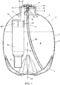
- Fig. 1 shows schematically and in partly sectional side elevation a holder 1, comprising a container 2, for instance wholly or partly filled with beverage 3, and a dispensing device 4.
- the beverage 3 can be beer.
- the holder container 2 may be formed as a blown plastic bottle.
- the container 2 may be rotation molded, injection molded or otherwise manufactured wholly or partly from plastic.
- the container 2 is provided with a body 5, a neck 6 and a bottom 7.
- the bottom 7 may for instance be a "petal" bottom having for instance three, four or five supporting feet. In this way, a self-standing bottle can be obtained, which can moreover be resistant to relatively high internal pressures, for instance five bars or more.
- the bottle may for instance be provided with a stand ring (not shown) on which the bottle can stand.
- This ring may for instance be formed-on, glued-on, clamped-on, integrally injection molded or provided otherwise.
- the body 5 may be global so as to be able to resist internal pressure in a simple manner. However, it can also have a different shape.
- the body 5, the bottom 7 and the neck 6 substantially define an inner space 8, in which the beverage 3 is received. In the inner space 8 extends, substantially, the dispensing device 4.
- the dispensing device 4 in this embodiment comprises for instance a device as known from NL 1008601 , for instance as shown in Figs. 1 to 3 thereof.
- Other examples of possible embodiments of dispensing devices 4 and/or pressure devices 9 to be used therein are for instance known from EP 1 140 658 , WO 2005/095229 , EP 1 642 861 , U.S. 5,368,207 or from the non-prepublished patent applications of applicant, titled “Pressure regulator and tapping apparatus provided therewith” or “Tapping apparatus, provided with a pressure regulating device", filed on March 31, 2008.
- a pressure device 9 in the embodiment shown comprises an aerosol container 10 as a storage reservoir, closed off by an aerosol valve (not shown).
- a pressure-controlled regulating unit 11 as a pressure regulating device is fixed on the aerosol container 10, such that the aerosol valve can be opened by the regulating unit 11 if the pressure in the inner space 8 falls below a desired pressure.
- the pressure device 9 operatively regulates the pressure in the inner space to an equilibrium pressure of CO 2 in the beverage, at a desired temperature, for instance a pressure between approximately 1.2 and 2 bar absolute, more particularly between approximately 1.4 and 1.6 bar between for instance 0 and 15 °C, for instance at approximately 6 °C.
- a suitable pressure can be set.
- the pressure device 9 with the container 10 which may for instance be manufactured from metal, is suspended by a bottom 12 from the side of the neck 6.
- the regulating unit 11 in the position shown in Fig. 1 is hence directed downwards, facing towards the bottom 7. It will be clear, however, that the actual position during use naturally also depends on the orientation of the holder 1. In Fig. 1 the latter is set up on the bottom 7.
- the pressure device 9 is suspended in a bracket 13, for instance manufactured from plastic, which bracket 13 comprises a clamping ring 14 which can clampingly embrace a part 45 of the container 10 contiguous to the bottom 12.
- the container 10 or pressure device 9 as such may be fixed to the bracket 13 in a different manner, for instance by gluing, by cooperating clamping means on the bracket 13 and/or the container 10 and/or the regulating unit 11.
- the bracket 13 On the side of the neck 6 the bracket 13 is attached to or provided with a suspension ring 15.
- the suspension ring 15 is substantially disc-shaped and rests by an edge 16 at the lower side 17 on an upper side 18 of the neck 6.
- a clamping ring 19 is provided, within the neck 6, in which a ring 20 which is attached to the upper side of the bracket 13 is clamped.
- the bracket 13 is formed integrally with the suspension ring 15 or is fixed thereto in a different manner, for instance by welding, gluing, snap-fitting, screws or otherwise.
- the suspension ring 15 is provided with a central opening 21, around which, at the upper side of the ring 15, an edge 22 extends.
- a valve 23, in particular an aerosol valve type valve 23 is arranged, as is also used in, for instance, a TapvatTM keg of Heineken, Netherlands, and as described, for instance, in EP 99960036.4 .
- the valve 23 is provided with a sleeve 24 in which a spring 25 is supported.
- the spring 25 presses a valve body 26 against a valve seat 27, for instance a plastic or rubber ring. When the valve body 26 is pushed down, off the seat 27, beverage can pass the valve body 26 and be dispensed.
- a riser 28 which extends to a point near the bottom 7.
- the sleeve 24, which may for instance be made of metal, is fixed in a clinch plate 29.
- the clinch plate 29 is fixed by an outer edge 30 thereof over the edge 22.
- the outer edge 30 may for instance be clinched over the edge 22. Surprisingly, this has been found to be very well possible when the clinch plate 29 is manufactured from metal such as steel or aluminum and the ring 15 from plastic.
- the suspension ring 15 is provided, at the lower side 17, with a groove 31 which can be slid over the upper side 18 of the neck 6 with a relatively close fit.
- an edge 32 may be provided, for instance an edge 32 having a slightly pointed cross section, for instance substantially triangular or parabolic.
- the edge 32 preferably has a height that is smaller than the depth of the groove 31, so that in that position the groove 31 has respective longitudinal edges 33 abutting against the inside and outside of the neck 6, which is thereby properly positioned. In this condition, the suspension ring 15 can be fixed onto the neck 6.
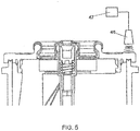
- a welding technique such that a part of the material of the neck 6 and/or the suspension ring 15, including the edge 32, if present, melts at least partly.
- a good contact surface is obtained and upon cooling of the material a firm connection between the neck and the suspension ring 15 will be obtained.
- ultrasonic welding technique as schematically represented in Fig. 5 , in which schematically a horn (loudspeaker) 46 of an ultrasonic welder 47 is directed at the suspension ring 15 and neck 6.
- An advantage of use of welding technique is that it will yield particularly good connections, also when for instance parts of the ring 15 and/or the neck 6 are moist, for instance as a result of filling of the container 2 with beverage.
- the connection can also be obtained after the holder has been filled.
- the connection is preferably not reversible. This means that a user cannot open the holder, for instance, by separating the suspension ring 15 from the neck. In this way, the chance of contamination or any other tampering with the beverage is prevented.
- the suspension ring 15 forms a closure.
- the suspension ring can have a central area around the opening 21 that is thinner than the edge 16.
- the central area can form a closing surface, with the edge possibly standing up from the central area.
- the suspension bracket 13 is so designed that the pressure device 9 is suspended in a position offset with respect to a centerline H of the neck 6 and, in the embodiment shown, the longitudinal axis or centerline H 1 of the holder 1.
- the clamping ring 14 is mounted eccentrically to the bracket 13.
- the pressure device 9 may for instance be suspended such that a filling pipe 34 (shown in broken lines in Fig. 2 ) of a filling installation (not shown) can be inserted through the opening 21, parallel to the longitudinal axis H 1 of the neck 6 and/or holder 1, without the pressure device 9 being touched thereby.
- the neck 6 preferably has a circular cross section with a radius of more than 13 mm or a passage area with a cross-sectional surface of more than 530 mm 2 .
- the radius can for instance be between about 13 and about 20 mm, preferably between about 13 mm and 16 mm, or the surface may be of comparable proportions.
- a rising surface 36 is provided, having an inclining edge 37.
- a rising surface 36 for instance extends from approximately near the longitudinal axis H of the neck adjacent the suspension ring 15 to the suspension bracket 13 approximately adjacent a middle of the bracket 13, viewed in the height direction of the holder 1.
- the or each rising surface 36 is preferably so arranged that if the pressure device 9 is inserted through the neck 6 and, for instance, released, the pressure device 9 is forced into the inner space 8 under the influence of gravity and at the same time is pushed to the side by the rising surfaces 36 until the suspension ring 15 butts against the neck 6. In this way, the pressure device 9 is particularly simply and substantially automatically brought into the correct position.
- the suspension ring 15 is supported on the upper side of the neck 6.
- An advantage of such a construction may be that the pressure device can be brought to its position by gravity and will not fall farther into the container. Moreover, this can simplify welding. However, naturally also other configurations can be used, so long as the suspension means and the neck 6 are mutually weldable.
- a dispensing tube 40 which via an operating button 41 with a channel part 42 is inserted into the valve 23, in particular into the valve body 26.
- the operating button 41 is pressed down, the valve 23 is opened and beverage can be dispensed from the inner space 8, via the dispensing tube 40.
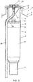
- Figs. 3 and 4 an alternative embodiment is shown of a part of a holder 1 according to the invention.
- the pressure device 9 is suspended straight under the neck 6.
- the suspension ring 15 is fixed onto the neck 6, in particular by welding technique, more particularly by ultrasonic welding.
- the bracket 13 in this embodiment is substantially tubular, with an inclined surface 37 being arranged, such that when a riser 28 is inserted through the opening 21, it is pushed aside and bent, such that it is simply forced alongside the pressure device 9 and at least alongside the container 10.
- An opening 38 may be provided near a lower side of the surface 37, to which a tube 39 is connected which guides the riser in the right direction.
- the container may be filled prior to placement of the pressure device but may also be filled through the opening 21. Openings 47 are provided, through which the beverage such as beer can flow, via the tubular bracket 13, into the inner space 8.
- the holder 2 or at least the neck 6 thereof may be manufactured from a weldable, in particular an ultrasonically weldable plastic, such as for instance PET, PEN, PE, PP or the like, which plastic is moreover preferably recyclable. It is preferred to use a plastic allowing the container 2 to be blown from it, in particular with a relatively thick wall thickness, being for instance, though no limited to, thicknesses between a few tenths of millimeters and a few millimeters, in order to obtain a container 2 which is pressure-resistant at the earlier-mentioned pressures or higher.
- the suspension ring 15 may be manufactured from a plastic compatible therewith.
- the container 2 and the suspension ring 15 are manufactured from PET or a blend thereof.
- the bracket 13 may be manufactured from a different plastic or the same plastic.
- the whole suspension of the pressure device in the container 2 may also be manufactured, for instance, by 2K, or more K, injection molding.
- the suspension ring 15 is at least partly translucent, in particular in that part where the suspension ring 15 is connected with the container 2.
- the weld between the suspension ring 15 and the container 2, in particular the neck 6, can be simply checked, in particular optically, for instance by visual inspection.
- Such an inspection can be carried out with the naked eye but can also be carried out, for instance, by a camera such as a CCD camera and image recognition software.
- other systems known per se from practice may be used to check such welds (semi)automatically.
- translucent should be understood to mean at the least, though not exclusively so, transmissive of a light frequency suitable for checking the joint mentioned.
- the suspension ring 15 at the edge 17 had a thickness of 3.0 mm, the edge 32 having an approximately triangular cross section of a height of 0.6 mm.
- the suspension ring 15 and neck 6 were manufactured from PET.
- the suspension ring 15 was welded to the neck 6 using an ultrasonic welder type USP-3000/5KW with Sonotrode TE20 104B2/1 of the firm Telsonic, with a setting of Welding pressure 2.9 bar; Powermax 5562 W; Energy 300Ws; holdtime 0.5 sec; Sonictime 110ms.
- Welding pressure 2.9 bar
- Powermax 5562 W Powermax 5562 W
- Energy 300Ws Holdtime 0.5 sec
- Sonictime 110ms a setting of the setting will depend inter alia on the materials used and the geometry used.
- the invention is not in any way limited to the embodiments represented in the description and drawings. Many variants within the framework of the invention outlined by the claims are possible. These include all combinations of parts of the embodiments shown.
- the container may be wholly or partly formed differently, a different beverage may be packaged and moreover the holder and the pressure device can have any desired shape and dimensions.
Description
- The invention relates to a device for storing beverage.
- Beverage such as carbonated beverage, for instance soft drink or beer, can be offered in, for instance, bottles, cans or kegs. When the beverage is packaged in a plastic bottle, usually a blown plastic bottle is used, having a neck which is closed off by a screw cap. For pouring out the beverage, the cap is unscrewed, whereupon a part of the beverage can be poured out and the cap can be screwed back onto the neck again.
- When beverage is packaged in a can or keg, usually an external pressure source is used, such as for instance a gas cylinder and dosing device for regulating pressure in the can or keg. The beverage is then dispensed under pressure via a tapping device configured for that purpose.
- From
EP 1064221 a device is known where in a plastic or metal container a pressure regulator is provided, which is for instance glued onto the bottom of the container or suspended from the cover. -
WO-A-02 38457 claim 1 and discloses a cask comprising a profiled sheath or liner forming a receptacle, obtained from at least two non-symmetrical parts welded together, one of said parts comprising an orifice provided with a neck. A filling/racking member is positioned in the neck of said orifice. In an embodiment, an upper part of the neck is welded to a remaining neck part. - An object of the invention is to provide a holder for beverage which is simple in structure and use. Another object of the invention is to provide a holder for beverage with which beverage can be dispensed under pressure. A further object of the invention is to provide a holder for beverage in which the beverage is protected from outside influences, such as contamination. These and/or other objects can be achieved with a holder or method according to the invention.
- In a first aspect, a holder for beverage according to this specification is characterized by a container manufactured substantially from plastic, provided with a neck having an opening, wherein the container is filled with beverage and on or in the neck a closure is provided. Through the closure extends a dispensing means. The closure is fixed to the neck utilizing at least welding technique. A pressure device is provided for pressurizing the beverage in the container for dispensing the beverage under pressure via the dispensing means. The pressure device in the container is suspended from the closure.
- The invention also provides a method for forming a beverage holder, wherein a plastic container with a neck is filled with beverage through the neck, wherein the neck is at least partly closed off by a closure, which closure is fixed to the neck by means of welding, in particular ultrasonic welding, such that the beverage can be dispensed from the container only by a dispensing means, in particular a dispensing means which extends through the closure, wherein a pressure regulator is introduced into the container through the neck, wherein the pressure regulator is suspended in and/or from the neck with the aid of the closure and is fixed by welding of the closure to the neck.
- The invention also provides a closure according to
claim 15. - In another aspect, a holder according to this specification is characterized in that in the holder a pressure regulator is suspended, with the aid of the closure, such that it is preferably suspended eccentrically of the neck, such that a filling pipe can be inserted into the holder alongside the pressure regulator, through the neck, for filling the holder.
- In clarification of the invention, embodiments of a holder or dispensing device and parts thereof and methods will be further elucidated with reference to the drawing. In the drawing:
-
Fig. 1 shows in partly sectional side elevation a first embodiment of a holder; -
Fig. 2 shows in magnification a portion of a holder according toFig. 1 , with a schematically represented dispensing tube; -
Fig. 3 shows in partly sectional side elevation a second embodiment of a holder; -
Fig. 4 shows in magnification a portion of a holder according toFig. 3 ; -
Fig. 5 schematically shows a portion of a holder according to the invention, with a pressure device being fixed onto the holder with the aid of a welding device, in particular an ultrasonic welding device. - In this description the same or corresponding parts have the same or corresponding reference numerals. The embodiments shown are shown only by way of illustration and should not be construed in any way as limiting. In this description, examples will be discussed and shown for dispensing beer, in particular lager-type beer. However, also other types of beverage can be dispensed from a device according to this specification. In this description the designation "lower" designates a side of a holder which is represented at the bottom in the figures. The designation "upper" is accordingly to be understood as being the opposite side.
-
Fig. 1 shows schematically and in partly sectional side elevation aholder 1, comprising acontainer 2, for instance wholly or partly filled withbeverage 3, and adispensing device 4. Thebeverage 3 can be beer. In an embodiment, theholder container 2 may be formed as a blown plastic bottle. In another embodiment, thecontainer 2 may be rotation molded, injection molded or otherwise manufactured wholly or partly from plastic. Thecontainer 2 is provided with abody 5, aneck 6 and a bottom 7. The bottom 7 may for instance be a "petal" bottom having for instance three, four or five supporting feet. In this way, a self-standing bottle can be obtained, which can moreover be resistant to relatively high internal pressures, for instance five bars or more. In another embodiment, the bottle may for instance be provided with a stand ring (not shown) on which the bottle can stand. This ring may for instance be formed-on, glued-on, clamped-on, integrally injection molded or provided otherwise. Thebody 5 may be global so as to be able to resist internal pressure in a simple manner. However, it can also have a different shape. Thebody 5, the bottom 7 and theneck 6 substantially define aninner space 8, in which thebeverage 3 is received. In theinner space 8 extends, substantially, thedispensing device 4. - The
dispensing device 4 in this embodiment comprises for instance a device as known fromNL 1008601 Figs. 1 to 3 thereof. Other examples of possible embodiments of dispensingdevices 4 and/orpressure devices 9 to be used therein are for instance known fromEP 1 140 658WO 2005/095229 ,EP 1 642 861U.S. 5,368,207 or from the non-prepublished patent applications of applicant, titled "Pressure regulator and tapping apparatus provided therewith" or "Tapping apparatus, provided with a pressure regulating device", filed on March 31, 2008. Thesedevices inner space 8 and/or through operation by a user, to regulate the pressure in theinner space 8 through introduction of gas under pressure from astorage reservoir 10 into theinner space 8, controlled by apressure regulating device 11. - A
pressure device 9 in the embodiment shown comprises anaerosol container 10 as a storage reservoir, closed off by an aerosol valve (not shown). A pressure-controlled regulatingunit 11 as a pressure regulating device is fixed on theaerosol container 10, such that the aerosol valve can be opened by the regulatingunit 11 if the pressure in theinner space 8 falls below a desired pressure. Preferably, as a result, thepressure device 9 operatively regulates the pressure in the inner space to an equilibrium pressure of CO2 in the beverage, at a desired temperature, for instance a pressure between approximately 1.2 and 2 bar absolute, more particularly between approximately 1.4 and 1.6 bar between forinstance 0 and 15 °C, for instance at approximately 6 °C. For instance for beverages other than beer, of course, in each case a suitable pressure can be set. - As shown in
Fig. 1 , thepressure device 9 with thecontainer 10, which may for instance be manufactured from metal, is suspended by abottom 12 from the side of theneck 6. The regulatingunit 11 in the position shown inFig. 1 is hence directed downwards, facing towards the bottom 7. It will be clear, however, that the actual position during use naturally also depends on the orientation of theholder 1. InFig. 1 the latter is set up on the bottom 7. Thepressure device 9 is suspended in abracket 13, for instance manufactured from plastic, whichbracket 13 comprises aclamping ring 14 which can clampingly embrace apart 45 of thecontainer 10 contiguous to thebottom 12. In another embodiment, thecontainer 10 orpressure device 9 as such may be fixed to thebracket 13 in a different manner, for instance by gluing, by cooperating clamping means on thebracket 13 and/or thecontainer 10 and/or the regulatingunit 11. - On the side of the
neck 6 thebracket 13 is attached to or provided with asuspension ring 15. In an embodiment, thesuspension ring 15 is substantially disc-shaped and rests by anedge 16 at thelower side 17 on anupper side 18 of theneck 6. At thelower side 17 of thesuspension ring 15, aclamping ring 19 is provided, within theneck 6, in which aring 20 which is attached to the upper side of thebracket 13 is clamped. Thebracket 13 is formed integrally with thesuspension ring 15 or is fixed thereto in a different manner, for instance by welding, gluing, snap-fitting, screws or otherwise. - The
suspension ring 15 is provided with acentral opening 21, around which, at the upper side of thering 15, anedge 22 extends. As is clearly visible inFig. 2 , avalve 23, in particular an aerosolvalve type valve 23, is arranged, as is also used in, for instance, a Tapvat™ keg of Heineken, Netherlands, and as described, for instance, inEP 99960036.4 valve 23 is provided with asleeve 24 in which aspring 25 is supported. Thespring 25 presses avalve body 26 against avalve seat 27, for instance a plastic or rubber ring. When thevalve body 26 is pushed down, off theseat 27, beverage can pass thevalve body 26 and be dispensed. Attached to thesleeve 24 at the lower side is ariser 28, which extends to a point near the bottom 7. Thesleeve 24, which may for instance be made of metal, is fixed in aclinch plate 29. Theclinch plate 29 is fixed by anouter edge 30 thereof over theedge 22. Theouter edge 30 may for instance be clinched over theedge 22. Surprisingly, this has been found to be very well possible when theclinch plate 29 is manufactured from metal such as steel or aluminum and thering 15 from plastic. - The
suspension ring 15 is provided, at thelower side 17, with agroove 31 which can be slid over theupper side 18 of theneck 6 with a relatively close fit. Within thegroove 31, anedge 32 may be provided, for instance anedge 32 having a slightly pointed cross section, for instance substantially triangular or parabolic. As a result, thesuspension ring 15, when laid onto theupper side 18 of the neck, will be supported on theedge 31, so that a relatively small contact surface is obtained. Theedge 32 preferably has a height that is smaller than the depth of thegroove 31, so that in that position thegroove 31 has respectivelongitudinal edges 33 abutting against the inside and outside of theneck 6, which is thereby properly positioned. In this condition, thesuspension ring 15 can be fixed onto theneck 6. To that end, preferably, use is made of a welding technique, such that a part of the material of theneck 6 and/or thesuspension ring 15, including theedge 32, if present, melts at least partly. As a result, a good contact surface is obtained and upon cooling of the material a firm connection between the neck and thesuspension ring 15 will be obtained. In an advantageous embodiment, use is made of ultrasonic welding technique, as schematically represented inFig. 5 , in which schematically a horn (loudspeaker) 46 of anultrasonic welder 47 is directed at thesuspension ring 15 andneck 6. An advantage of use of welding technique, in particular ultrasonic welding technique, is that it will yield particularly good connections, also when for instance parts of thering 15 and/or theneck 6 are moist, for instance as a result of filling of thecontainer 2 with beverage. As a consequence, the connection can also be obtained after the holder has been filled. The connection is preferably not reversible. This means that a user cannot open the holder, for instance, by separating thesuspension ring 15 from the neck. In this way, the chance of contamination or any other tampering with the beverage is prevented. Thesuspension ring 15 forms a closure. The suspension ring can have a central area around theopening 21 that is thinner than theedge 16. The central area can form a closing surface, with the edge possibly standing up from the central area. - In the embodiment shown in
Figs. 1 and2 , thesuspension bracket 13 is so designed that thepressure device 9 is suspended in a position offset with respect to a centerline H of theneck 6 and, in the embodiment shown, the longitudinal axis or centerline H1 of theholder 1. To this end, the clampingring 14 is mounted eccentrically to thebracket 13. Thepressure device 9 may for instance be suspended such that a filling pipe 34 (shown in broken lines inFig. 2 ) of a filling installation (not shown) can be inserted through theopening 21, parallel to the longitudinal axis H1 of theneck 6 and/orholder 1, without thepressure device 9 being touched thereby. This provides the advantage that thepressure device 9 can also be placed prior to filling of theholder 1, without the filling device needing to be adapted. A fillingpipe 34 can be inserted into theholder 1 to a point near the bottom 7. After filling, thevalve 23 can then be arranged and fixed, for instance by clinching or otherwise. Theneck 6 preferably has a circular cross section with a radius of more than 13 mm or a passage area with a cross-sectional surface of more than 530 mm2. The radius can for instance be between about 13 and about 20 mm, preferably between about 13 mm and 16 mm, or the surface may be of comparable proportions. In this way, thepressure device 9 with sufficient volume can be simply introduced through theneck 6 while thecontainer 10 thereof may be cylindrical. Owing to the welding technique, in particular ultrasonic welding, no screw cap needs to be used. - In the embodiment shown in
Figs. 1 and2 , between thebracket 13 and thesuspension ring 15, at least one risingsurface 36 is provided, having an incliningedge 37. Viewed in side elevation, a risingsurface 36 for instance extends from approximately near the longitudinal axis H of the neck adjacent thesuspension ring 15 to thesuspension bracket 13 approximately adjacent a middle of thebracket 13, viewed in the height direction of theholder 1. The or each risingsurface 36 is preferably so arranged that if thepressure device 9 is inserted through theneck 6 and, for instance, released, thepressure device 9 is forced into theinner space 8 under the influence of gravity and at the same time is pushed to the side by the risingsurfaces 36 until thesuspension ring 15 butts against theneck 6. In this way, thepressure device 9 is particularly simply and substantially automatically brought into the correct position. - In the embodiments shown, the
suspension ring 15 is supported on the upper side of theneck 6. An advantage of such a construction may be that the pressure device can be brought to its position by gravity and will not fall farther into the container. Moreover, this can simplify welding. However, naturally also other configurations can be used, so long as the suspension means and theneck 6 are mutually weldable. - In
Fig. 2 there is schematically shown a dispensingtube 40 which via an operating button 41 with achannel part 42 is inserted into thevalve 23, in particular into thevalve body 26. When the operating button 41 is pressed down, thevalve 23 is opened and beverage can be dispensed from theinner space 8, via the dispensingtube 40. - In
Figs. 3 and4 an alternative embodiment is shown of a part of aholder 1 according to the invention. In broad outline, it is equal to the holder according toFigs. 1 and2 , however, thepressure device 9 is suspended straight under theneck 6. Again, thesuspension ring 15 is fixed onto theneck 6, in particular by welding technique, more particularly by ultrasonic welding. Thebracket 13 in this embodiment is substantially tubular, with aninclined surface 37 being arranged, such that when ariser 28 is inserted through theopening 21, it is pushed aside and bent, such that it is simply forced alongside thepressure device 9 and at least alongside thecontainer 10. Anopening 38 may be provided near a lower side of thesurface 37, to which a tube 39 is connected which guides the riser in the right direction. The container may be filled prior to placement of the pressure device but may also be filled through theopening 21.Openings 47 are provided, through which the beverage such as beer can flow, via thetubular bracket 13, into theinner space 8. - In an embodiment, the
holder 2 or at least theneck 6 thereof may be manufactured from a weldable, in particular an ultrasonically weldable plastic, such as for instance PET, PEN, PE, PP or the like, which plastic is moreover preferably recyclable. It is preferred to use a plastic allowing thecontainer 2 to be blown from it, in particular with a relatively thick wall thickness, being for instance, though no limited to, thicknesses between a few tenths of millimeters and a few millimeters, in order to obtain acontainer 2 which is pressure-resistant at the earlier-mentioned pressures or higher. Thesuspension ring 15 may be manufactured from a plastic compatible therewith. Compatible should herein be understood to refer to a plastic that is weldable, in particular ultrasonically weldable, with the plastic of theneck 6. In an embodiment, thecontainer 2 and thesuspension ring 15 are manufactured from PET or a blend thereof. Thebracket 13 may be manufactured from a different plastic or the same plastic. The whole suspension of the pressure device in thecontainer 2 may also be manufactured, for instance, by 2K, or more K, injection molding. These examples merely serve for illustration and should not be construed in any way as limiting. - In an advantageous embodiment, the
suspension ring 15 is at least partly translucent, in particular in that part where thesuspension ring 15 is connected with thecontainer 2. In this way, the weld between thesuspension ring 15 and thecontainer 2, in particular theneck 6, can be simply checked, in particular optically, for instance by visual inspection. Such an inspection can be carried out with the naked eye but can also be carried out, for instance, by a camera such as a CCD camera and image recognition software. Also, other systems known per se from practice may be used to check such welds (semi)automatically. Herein, translucent should be understood to mean at the least, though not exclusively so, transmissive of a light frequency suitable for checking the joint mentioned. - In the description an example has been given of a configuration of the cooperating edge of the suspension ring and the neck of the container, in particular an upper side thereof. Many variations thereon are possible, as for instance known from publications of the firm of Sonitek - Sonic & Thermal Technologies, Inc, Milford. These and comparable configurations can be used in a
holder 1 according to the invention. A choice from the possible configurations can be readily made by one skilled in the art, depending on the specifications chosen. In an exemplary embodiment, thesuspension ring 15 at theedge 17 had a thickness of 3.0 mm, theedge 32 having an approximately triangular cross section of a height of 0.6 mm. Thesuspension ring 15 andneck 6 were manufactured from PET. Thesuspension ring 15 was welded to theneck 6 using an ultrasonic welder type USP-3000/5KW with Sonotrode TE20 104B2/1 of the firm Telsonic, with a setting of Welding pressure 2.9 bar; Powermax 5562 W; Energy 300Ws; holdtime 0.5 sec; Sonictime 110ms. Naturally, also other ultrasonic welding devices can be used and the setting will depend inter alia on the materials used and the geometry used. - The invention is not in any way limited to the embodiments represented in the description and drawings. Many variants within the framework of the invention outlined by the claims are possible. These include all combinations of parts of the embodiments shown. For instance, the container may be wholly or partly formed differently, a different beverage may be packaged and moreover the holder and the pressure device can have any desired shape and dimensions.
Claims (15)
- A holder for beverage, comprising a container (2) manufactured substantially from plastic, provided with a neck (6) having an opening, wherein the container (2) is filled with beverage and on or in the neck (6) a closure (15) is provided, through which closure extends a dispensing means (4), wherein the closure (15) is fixed to the neck (6) with the aid of at least welding technique and wherein a pressure device (9, 10, 11) is provided for pressurizing the beverage in the container (2) for dispensing the beverage under pressure via the dispensing means (4), characterized in that the pressure device (9, 10, 11) in the container (2) is suspended from the closure (15).
- A holder according to claim 1, wherein the closure (15) is fixed to the neck (6) by ultrasonic welding.
- A holder according to claim 2, wherein the closure (15) comprises a flange provided with an edge and a closing face, wherein the edge on at least one side of the closing face stands up to some extent.
- A holder according to any one of the preceding claims, wherein the closure (15) comprises a flange with an edge and a central area, wherein the edge is thicker than the central area.
- A holder according to any one of the preceding claims, wherein the neck (6) has an opening with a substantially circular cross section with a radius of more than 13 mm or a passage with a cross-sectional area of more than 530 mm2.
- A holder according to any one of the preceding claims, wherein the closure (15) is welded onto an upper edge of the neck (6).
- A holder according to any one of the preceding claims, wherein the container (2) is a blown plastic bottle.
- A holder according to any one of the preceding claims, wherein the bottle is manufactured from PET or PEN or a blend of PET and/or PEN.
- A holder according to any one of the preceding claims, wherein the pressure device (9, 10, 11) is included in the container (2).
- A holder according to claim 9, wherein the pressure device (9, 10, 11) comprises a pressure cartridge (10) filled with gas, as well as a pressure regulating device (11) with which gas can be introduced into the container (2) in a dosed manner.
- A holder according to claim 10, wherein the pressure regulating device (11) is configured for pressure-controlled regulation of the pressure in the container (2), wherein the beverage is preferably carbonated beverage and the pressure regulating device (11) is preferably configured for regulating the pressure in the container (2) at approximately the level of an equilibrium pressure of carbon dioxide in the beverage at a temperature between 0 and 15 degrees Centigrade.
- A holder according to any of the preceding claims, wherein the neck (6) has a longitudinal axis and the pressure device (9, 10, 11) is suspended in the container (2) eccentrically with respect to the longitudinal axis, wherein, viewed in the direction of the longitudinal axis, the pressure device (9, 10, 11) is preferably suspended substantially next to the neck (6), within the container (2).
- A method for forming a beverage holder, wherein a plastic container (2) with a neck (6) is filled with beverage through the neck (6), wherein the neck (6) is at least partly closed off by a closure (15), which closure is fixed to the neck (6) by means of welding, such that the beverage can be dispensed from the container (2) only by a dispensing means (4), wherein a pressure regulator (9, 10, 11) is introduced into the container (2) through the neck (6), wherein the pressure regulator (9, 10, 11) is suspended in and/or from the neck (6) with the aid of the closure (15) and is fixed by welding of the closure (15) to the neck (6).
- A method according to claim 13, wherein the container (2) is blown from plastic, while the closure (15) is formed with a flange of plastic which is weldable with the neck (6).
- A closure for closing off a neck of a beverage container, which closure (15) comprises a flange for welding to a neck (6) of a beverage container (2) and is provided with a suspension means (13) for suspending a pressure regulator (9, 10, 11) therefrom within the beverage container (2), wherein the suspension means comprise a suspension ring (15) and a bracket (13), wherein the bracket (13) is formed integrally with the suspension ring (15) or is fixed thereto..
Priority Applications (1)
| Application Number | Priority Date | Filing Date | Title |
|---|---|---|---|
| PL09730470T PL2291321T6 (en) | 2008-04-10 | 2009-04-08 | Container for holding and dispensing a pressurised beverage |
Applications Claiming Priority (2)
| Application Number | Priority Date | Filing Date | Title |
|---|---|---|---|
| NL2001467A NL2001467C2 (en) | 2008-04-10 | 2008-04-10 | Device for keeping drinks. |
| PCT/NL2009/050184 WO2009126034A1 (en) | 2008-04-10 | 2009-04-08 | Container for holding and dispensing a pressurised beverage |
Publications (4)
| Publication Number | Publication Date |
|---|---|
| EP2291321A1 EP2291321A1 (en) | 2011-03-09 |
| EP2291321B1 EP2291321B1 (en) | 2011-10-26 |
| EP2291321B2 true EP2291321B2 (en) | 2020-04-22 |
| EP2291321B3 EP2291321B3 (en) | 2021-04-07 |
Family
ID=40316949
Family Applications (2)
| Application Number | Title | Priority Date | Filing Date |
|---|---|---|---|
| EP09730470.3A Active EP2291321B3 (en) | 2008-04-10 | 2009-04-08 | Container for holding and dispensing a pressurised beverage |
| EP09729565A Active EP2282947B1 (en) | 2008-04-10 | 2009-04-08 | Container for holding and dispensing a pressurised beverage, method and valve therefor |
Family Applications After (1)
| Application Number | Title | Priority Date | Filing Date |
|---|---|---|---|
| EP09729565A Active EP2282947B1 (en) | 2008-04-10 | 2009-04-08 | Container for holding and dispensing a pressurised beverage, method and valve therefor |
Country Status (23)
| Country | Link |
|---|---|
| US (2) | US8950636B2 (en) |
| EP (2) | EP2291321B3 (en) |
| JP (2) | JP2011517646A (en) |
| CN (2) | CN102056810A (en) |
| AR (2) | AR071199A1 (en) |
| AT (1) | ATE530493T2 (en) |
| AU (2) | AU2009234559A1 (en) |
| BR (2) | BRPI0911253A2 (en) |
| CA (2) | CA2720915A1 (en) |
| CL (2) | CL2009000869A1 (en) |
| DK (2) | DK2282947T3 (en) |
| ES (2) | ES2391065T3 (en) |
| HR (1) | HRP20120054T1 (en) |
| MX (2) | MX2010011119A (en) |
| NL (2) | NL2001467C2 (en) |
| NZ (2) | NZ588520A (en) |
| PL (2) | PL2291321T6 (en) |
| PT (2) | PT2282947E (en) |
| RU (2) | RU2533721C2 (en) |
| SI (1) | SI2291321T1 (en) |
| TW (2) | TW200948703A (en) |
| WO (2) | WO2009126034A1 (en) |
| ZA (2) | ZA201007515B (en) |
Families Citing this family (18)
| Publication number | Priority date | Publication date | Assignee | Title |
|---|---|---|---|---|
| BR112012028044A2 (en) * | 2010-06-02 | 2016-08-02 | Heineken Supply Chain Bv | beverage container unit, and method for providing a beverage container unit |
| HUP1000286A2 (en) * | 2010-06-02 | 2011-12-28 | Mayex Canada Kft | Dispensing unit and method for dispensing a liquid under pressure |
| BR102012021408B1 (en) | 2012-08-24 | 2020-09-29 | Gustavo Foresti Fezer | PACKAGING FOR FILLING AND SPRAYING OF DRINKED BEVERAGES |
| NL2009732C2 (en) | 2012-10-30 | 2014-05-06 | Heineken Supply Chain Bv | Beverage container and valve for a beverage container. |
| NL2009731C2 (en) | 2012-10-30 | 2014-05-06 | Heineken Supply Chain Bv | Container and valve for a container. |
| NL2009864C2 (en) | 2012-11-22 | 2014-05-27 | Heineken Supply Chain Bv | Beverage dispensing assembly and container for use in a beverage dispensing assembly. |
| US20140326143A1 (en) * | 2013-05-06 | 2014-11-06 | 16 MILE BREWING COMPANY Inc. | Imbrue keg infusion apparatus and system |
| EP2803631A1 (en) | 2013-05-16 | 2014-11-19 | Carlsberg Breweries A/S | A beverage dispensing system and a method of dispensing beverage |
| NL2012199C2 (en) | 2014-02-04 | 2015-08-06 | Heineken Supply Chain Bv | Dispensing assembly and container with tap. |
| NL2012200C2 (en) * | 2014-02-04 | 2015-08-06 | Heineken Supply Chain Bv | Beverage dispensing assembly and tap. |
| WO2015183752A1 (en) | 2014-05-24 | 2015-12-03 | GrowlerWerks, INC. | Beverage dispenser and variable presure regulator cap assembly |
| NL2012981B1 (en) * | 2014-06-11 | 2017-01-17 | Heineken Supply Chain Bv | Beverage dispensing system, beverage container and pressurizing system for use in a beverage dispensing system or container. |
| PT109389A (en) * | 2016-05-16 | 2017-12-06 | Novadelta - Comércio E Indústria De Cafés S A | AROMATIC DRINKS PREPARATION SYSTEM WITH OPTIMIZED DRINK DISCHARGE DISPOSAL AND OPERATION PROCEDURE OF THE SYSTEM |
| NL2017109B1 (en) | 2016-07-05 | 2018-01-12 | Heineken Supply Chain Bv | Beverage dispensing assembly and beverage container |
| NL2018956B1 (en) | 2017-05-19 | 2018-11-28 | Heineken Supply Chain Bv | Beverage dispensing assembly and beverage container |
| NL2018955B1 (en) | 2017-05-19 | 2018-11-28 | Heineken Supply Chain Bv | Beverage dispensing assembly and beverage container |
| CN110203559A (en) * | 2019-06-26 | 2019-09-06 | 广东美妆优品科技有限责任公司 | A kind of aerosol bottle |
| WO2021235934A1 (en) * | 2020-05-19 | 2021-11-25 | Heineken Supply Chain B.V. | Valve for a beverage container |
Family Cites Families (47)
| Publication number | Priority date | Publication date | Assignee | Title |
|---|---|---|---|---|
| US2547052A (en) * | 1946-02-05 | 1951-04-03 | Kidde Mfg Co Inc | Siphon bottle with aeration and dispensing control means |
| US3245435A (en) * | 1963-12-12 | 1966-04-12 | Colgate Palmolive Co | Pressurized dispenser with propellant bag |
| US3251420A (en) | 1964-04-20 | 1966-05-17 | Fire Guard Corp | Fire extinguisher with bottom mounted cartridge |
| US3613954A (en) * | 1968-06-20 | 1971-10-19 | Schlitz Brewing Co J | Dispensing apparatus |
| US3632023A (en) * | 1970-03-16 | 1972-01-04 | Republic Corp | Tapping device for beer kegs and the like |
| SE364931B (en) * | 1972-09-27 | 1974-03-11 | Bygg Och Transportekonomie Ab | |
| US3955720A (en) * | 1972-11-15 | 1976-05-11 | Malone David C | Low pressure dispensing apparatus with air pump |
| US3815798A (en) * | 1973-05-21 | 1974-06-11 | B Lavitch | Button fastener |
| US3964649A (en) * | 1975-01-30 | 1976-06-22 | Lever Brothers Company | Pressurized dispensing container |
| US4174811A (en) * | 1977-02-15 | 1979-11-20 | Firma Airotechnik Siegfried Binder Gmbh | Fluid substance sprayer having propellant gas and substance refill |
| US4121772A (en) | 1977-08-17 | 1978-10-24 | Rubin Mandrell | Portable spray can for dual liquids |
| US4147283A (en) | 1977-09-21 | 1979-04-03 | The Continental Group, Inc. | Combined charging and product dispensing unit |
| FR2411798A1 (en) * | 1977-12-19 | 1979-07-13 | Waterlomat Sa | APPARATUS FOR BLOWING CARBONATE BEVERAGES CONTAINED IN CONTAINERS WITH BUILT-IN GAS RESERVE |
| US4310108A (en) * | 1978-06-08 | 1982-01-12 | Freund Industrial Co., Ltd. | Aerosol sprayer with pressure reservoir |
| SE423610B (en) | 1978-08-11 | 1982-05-17 | Tetra Pak Dev | SET TO MAKE PACKAGING CONTAINERS OF PLASTIC MATERIAL BUT PACKAGING CONTAINERS MANUFACTURED AS SET |
| US4632276A (en) * | 1983-12-30 | 1986-12-30 | Yukio Makino | Liquid dispensing device |
| US4595127A (en) * | 1984-05-21 | 1986-06-17 | Stoody William R | Self-contained fluid pump aerosol dispenser |
| JPS62260682A (en) * | 1986-05-01 | 1987-11-12 | 三菱商事株式会社 | Teeming device |
| EP0281607A4 (en) * | 1986-09-09 | 1989-04-24 | Dispak Pty Ltd | Liquid dispenser. |
| US5246140A (en) * | 1988-06-23 | 1993-09-21 | Micro Matic A/S | Container device for distributing a drinkable liquid under pressure from a gas |
| US5110012A (en) * | 1991-01-11 | 1992-05-05 | Scholle Corporation | Beverage container with regulated pressure |
| EP0945369A1 (en) | 1992-04-30 | 1999-09-29 | I.P.R.S., U.S.A. | Dispensing apparatus including a pressure generator |
| BR9304369A (en) | 1993-10-26 | 1995-06-20 | Imi Cornelius Brasil Ltda | Liquid extractor assembly from a container |
| RU2063915C1 (en) | 1994-02-14 | 1996-07-20 | Центр комплексного развития технологии и энерготехнологических систем "Кортэс" | Spraying container and methods of its charging |
| NL1008601C2 (en) | 1998-03-16 | 1999-09-17 | Heineken Tech Services | Device for dispensing a fluid. |
| GB2335902A (en) | 1998-04-01 | 1999-10-06 | Miracle Beer Company Limited | Micro-brewing device |
| JPH11319649A (en) * | 1998-05-19 | 1999-11-24 | Young:Kk | Aerosol device |
| JP2000085866A (en) * | 1998-09-07 | 2000-03-28 | Seiichi Kitabayashi | Synthetic resin-made pressure container for aerosol ejection |
| PT1140692E (en) | 1998-12-16 | 2003-04-30 | Heineken Tech Services | CONTAINER FOR STORAGE AND DISTRIBUTION OF BEVERAGES PARTICULARLY OF BEER |
| IL143715A (en) | 1998-12-16 | 2005-12-18 | Heineken Tech Services | Container for dispensing fluid comprising a pressure control device with activation step |
| US6276565B1 (en) * | 1999-05-11 | 2001-08-21 | Arichell Technologies, Inc. | Gas-driven liquid dispenser employing separate pressurized-gas source |
| JP2001233389A (en) * | 2000-02-21 | 2001-08-28 | Mitani Valve Co Ltd | Aerosol container |
| EP1317395B1 (en) * | 2000-08-16 | 2010-01-13 | Walter K. Lim | Gas storage and delivery system for pressurized containers |
| FR2816599B1 (en) | 2000-11-10 | 2003-03-14 | Denis Delbarre | WAS LIQUID WITH PRESSURE CURING MEANS |
| NL1019562C2 (en) * | 2001-12-13 | 2003-06-17 | Heineken Tech Services | Valve assembly for use with beverage delivery. |
| NL1023968C2 (en) | 2003-07-21 | 2005-01-24 | Heineken Tech Services | Pressure regulator for carbonated beverage container. |
| AU2004259052B2 (en) | 2003-07-30 | 2010-03-11 | Rm Beteilgungs Ag | Plastic drinks bottle with cap |
| EP1504999A1 (en) | 2003-08-05 | 2005-02-09 | Amcor Limited | Rigid plastic container having gas-barrier properties and high transparency |
| DK1725476T3 (en) * | 2004-01-30 | 2008-03-03 | Intelligent Packaging Systems | Pressure control device |
| DE102004017171A1 (en) | 2004-04-02 | 2005-10-20 | Huber Verpackungen Gmbh & Co K | Device for dispensing a fluid from a cavity of a container |
| DE102004047252A1 (en) * | 2004-09-29 | 2006-04-13 | Kurt Oberhofer | liquid container |
| EP1688813A1 (en) | 2005-02-02 | 2006-08-09 | Impress GmbH & Co. oHG | Pressure regulator with piercing device for gas cartridge mountable within the keg closure |
| EP1954569A1 (en) * | 2005-11-29 | 2008-08-13 | Rexam Petainer Lidköping Ab | Method of filling and stabilising a thin-walled container |
| NL1031410C2 (en) | 2006-03-20 | 2007-09-21 | Heineken Supply Chain Bv | Beverage container and assembly of such a container and a tapping device. |
| NL1032709C2 (en) | 2006-10-20 | 2008-04-22 | Konink Grolsch N V | Device for dispensing a liquid. |
| NL1032892C2 (en) * | 2006-11-17 | 2008-05-20 | Heineken Supply Chain Bv | Tapping device with pressure control means. |
| US8070023B2 (en) * | 2007-03-09 | 2011-12-06 | On Tap Llc | Beverage dispensing assembly |
-
2008
- 2008-04-10 NL NL2001467A patent/NL2001467C2/en not_active IP Right Cessation
-
2009
- 2009-04-08 PT PT09729565T patent/PT2282947E/en unknown
- 2009-04-08 PT PT09730470T patent/PT2291321E/en unknown
- 2009-04-08 NZ NZ588520A patent/NZ588520A/en not_active IP Right Cessation
- 2009-04-08 AU AU2009234559A patent/AU2009234559A1/en not_active Abandoned
- 2009-04-08 US US12/936,860 patent/US8950636B2/en active Active
- 2009-04-08 ES ES09729565T patent/ES2391065T3/en active Active
- 2009-04-08 EP EP09730470.3A patent/EP2291321B3/en active Active
- 2009-04-08 PL PL09730470T patent/PL2291321T6/en unknown
- 2009-04-08 DK DK09729565.3T patent/DK2282947T3/en active
- 2009-04-08 MX MX2010011119A patent/MX2010011119A/en active IP Right Grant
- 2009-04-08 RU RU2010145533/12A patent/RU2533721C2/en active
- 2009-04-08 AU AU2009234558A patent/AU2009234558A1/en not_active Abandoned
- 2009-04-08 EP EP09729565A patent/EP2282947B1/en active Active
- 2009-04-08 WO PCT/NL2009/050184 patent/WO2009126034A1/en active Application Filing
- 2009-04-08 CA CA2720915A patent/CA2720915A1/en not_active Abandoned
- 2009-04-08 PL PL09729565T patent/PL2282947T3/en unknown
- 2009-04-08 JP JP2011503927A patent/JP2011517646A/en active Pending
- 2009-04-08 NZ NZ589064A patent/NZ589064A/en not_active IP Right Cessation
- 2009-04-08 AT AT09730470T patent/ATE530493T2/en active
- 2009-04-08 BR BRPI0911253A patent/BRPI0911253A2/en not_active IP Right Cessation
- 2009-04-08 SI SI200930148T patent/SI2291321T1/en unknown
- 2009-04-08 ES ES09730470T patent/ES2374792T7/en active Active
- 2009-04-08 RU RU2010145532/12A patent/RU2010145532A/en unknown
- 2009-04-08 WO PCT/NL2009/050185 patent/WO2009126035A2/en active Application Filing
- 2009-04-08 NL NL2002731A patent/NL2002731C2/en not_active IP Right Cessation
- 2009-04-08 US US12/936,864 patent/US8906438B2/en not_active Expired - Fee Related
- 2009-04-08 JP JP2011503928A patent/JP5358675B2/en not_active Expired - Fee Related
- 2009-04-08 CN CN2009801213248A patent/CN102056810A/en active Pending
- 2009-04-08 CA CA2721054A patent/CA2721054A1/en not_active Abandoned
- 2009-04-08 CN CN200980121416.6A patent/CN102056837B/en active Active
- 2009-04-08 BR BRPI0910913A patent/BRPI0910913A2/en not_active IP Right Cessation
- 2009-04-08 MX MX2010011118A patent/MX339708B/en active IP Right Grant
- 2009-04-08 DK DK09730470.3T patent/DK2291321T6/en active
- 2009-04-09 TW TW098111813A patent/TW200948703A/en unknown
- 2009-04-09 CL CL2009000869A patent/CL2009000869A1/en unknown
- 2009-04-09 CL CL2009000868A patent/CL2009000868A1/en unknown
- 2009-04-09 TW TW098111812A patent/TW200948702A/en unknown
- 2009-04-13 AR ARP090101296A patent/AR071199A1/en not_active Application Discontinuation
- 2009-04-13 AR ARP090101297A patent/AR071200A1/en not_active Application Discontinuation
-
2010
- 2010-10-21 ZA ZA2010/07515A patent/ZA201007515B/en unknown
- 2010-10-21 ZA ZA2010/07514A patent/ZA201007514B/en unknown
-
2012
- 2012-01-18 HR HR20120054T patent/HRP20120054T1/en unknown
Also Published As
Similar Documents
| Publication | Publication Date | Title |
|---|---|---|
| EP2291321B2 (en) | Container for holding and dispensing a pressurised beverage | |
| KR100532205B1 (en) | Assembly for storing and dispensing beer and other carbonated beverages | |
| EP1888450B1 (en) | Liquid storage and dispensing apparatus | |
| RU2430010C2 (en) | Reservoir for drink and unit assembled from such reservoir and dispenser | |
| MX2012000225A (en) | Tapping apparatus and compressible bottle therefore, and a preform for forming such container. | |
| US20090272712A1 (en) | Plastic drinks bottle with cap |
Legal Events
| Date | Code | Title | Description |
|---|---|---|---|
| PUAI | Public reference made under article 153(3) epc to a published international application that has entered the european phase |
Free format text: ORIGINAL CODE: 0009012 |
|
| 17P | Request for examination filed |
Effective date: 20101108 |
|
| AK | Designated contracting states |
Kind code of ref document: A1 Designated state(s): AT BE BG CH CY CZ DE DK EE ES FI FR GB GR HR HU IE IS IT LI LT LU LV MC MK MT NL NO PL PT RO SE SI SK TR |
|
| AX | Request for extension of the european patent |
Extension state: AL BA RS |
|
| GRAP | Despatch of communication of intention to grant a patent |
Free format text: ORIGINAL CODE: EPIDOSNIGR1 |
|
| DAX | Request for extension of the european patent (deleted) | ||
| GRAS | Grant fee paid |
Free format text: ORIGINAL CODE: EPIDOSNIGR3 |
|
| GRAA | (expected) grant |
Free format text: ORIGINAL CODE: 0009210 |
|
| AK | Designated contracting states |
Kind code of ref document: B1 Designated state(s): AT BE BG CH CY CZ DE DK EE ES FI FR GB GR HR HU IE IS IT LI LT LU LV MC MK MT NL NO PL PT RO SE SI SK TR |
|
| REG | Reference to a national code |
Ref country code: GB Ref legal event code: FG4D |
|
| REG | Reference to a national code |
Ref country code: CH Ref legal event code: EP |
|
| REG | Reference to a national code |
Ref country code: IE Ref legal event code: FG4D |
|
| REG | Reference to a national code |
Ref country code: CH Ref legal event code: NV Representative=s name: BOVARD AG |
|
| REG | Reference to a national code |
Ref country code: DE Ref legal event code: R096 Ref document number: 602009003347 Country of ref document: DE Effective date: 20111222 |
|
| REG | Reference to a national code |
Ref country code: HR Ref legal event code: TUEP Ref document number: P20120054 Country of ref document: HR |
|
| REG | Reference to a national code |
Ref country code: PT Ref legal event code: SC4A Free format text: AVAILABILITY OF NATIONAL TRANSLATION Effective date: 20120117 |
|
| REG | Reference to a national code |
Ref country code: SE Ref legal event code: TRGR |
|
| REG | Reference to a national code |
Ref country code: DK Ref legal event code: T3 |
|
| REG | Reference to a national code |
Ref country code: NL Ref legal event code: T3 |
|
| REG | Reference to a national code |
Ref country code: NO Ref legal event code: T2 Effective date: 20111026 |
|
| REG | Reference to a national code |
Ref country code: ES Ref legal event code: FG2A Ref document number: 2374792 Country of ref document: ES Kind code of ref document: T3 Effective date: 20120222 |
|
| REG | Reference to a national code |
Ref country code: HR Ref legal event code: T1PR Ref document number: P20120054 Country of ref document: HR |
|
| LTIE | Lt: invalidation of european patent or patent extension |
Effective date: 20111026 |
|
| REG | Reference to a national code |
Ref country code: PL Ref legal event code: T3 |
|
| REG | Reference to a national code |
Ref country code: SK Ref legal event code: T3 Ref document number: E 11000 Country of ref document: SK |
|
| REG | Reference to a national code |
Ref country code: GR Ref legal event code: EP Ref document number: 20120400102 Country of ref document: GR Effective date: 20120305 |
|
| PG25 | Lapsed in a contracting state [announced via postgrant information from national office to epo] |
Ref country code: LT Free format text: LAPSE BECAUSE OF FAILURE TO SUBMIT A TRANSLATION OF THE DESCRIPTION OR TO PAY THE FEE WITHIN THE PRESCRIBED TIME-LIMIT Effective date: 20111026 Ref country code: IS Free format text: LAPSE BECAUSE OF FAILURE TO SUBMIT A TRANSLATION OF THE DESCRIPTION OR TO PAY THE FEE WITHIN THE PRESCRIBED TIME-LIMIT Effective date: 20120226 |
|
| PG25 | Lapsed in a contracting state [announced via postgrant information from national office to epo] |
Ref country code: LV Free format text: LAPSE BECAUSE OF FAILURE TO SUBMIT A TRANSLATION OF THE DESCRIPTION OR TO PAY THE FEE WITHIN THE PRESCRIBED TIME-LIMIT Effective date: 20111026 |
|
| PG25 | Lapsed in a contracting state [announced via postgrant information from national office to epo] |
Ref country code: CY Free format text: LAPSE BECAUSE OF FAILURE TO SUBMIT A TRANSLATION OF THE DESCRIPTION OR TO PAY THE FEE WITHIN THE PRESCRIBED TIME-LIMIT Effective date: 20111026 |
|
| PLBI | Opposition filed |
Free format text: ORIGINAL CODE: 0009260 |
|
| PG25 | Lapsed in a contracting state [announced via postgrant information from national office to epo] |
Ref country code: EE Free format text: LAPSE BECAUSE OF FAILURE TO SUBMIT A TRANSLATION OF THE DESCRIPTION OR TO PAY THE FEE WITHIN THE PRESCRIBED TIME-LIMIT Effective date: 20111026 |
|
| 26 | Opposition filed |
Opponent name: CARLSBERG BREWERIES A/S Effective date: 20120725 |
|
| PLAX | Notice of opposition and request to file observation + time limit sent |
Free format text: ORIGINAL CODE: EPIDOSNOBS2 |
|
| REG | Reference to a national code |
Ref country code: DE Ref legal event code: R026 Ref document number: 602009003347 Country of ref document: DE Effective date: 20120725 |
|
| REG | Reference to a national code |
Ref country code: HU Ref legal event code: AG4A Ref document number: E014239 Country of ref document: HU |
|
| PG25 | Lapsed in a contracting state [announced via postgrant information from national office to epo] |
Ref country code: MC Free format text: LAPSE BECAUSE OF NON-PAYMENT OF DUE FEES Effective date: 20120430 |
|
| PLAF | Information modified related to communication of a notice of opposition and request to file observations + time limit |
Free format text: ORIGINAL CODE: EPIDOSCOBS2 |
|
| PG25 | Lapsed in a contracting state [announced via postgrant information from national office to epo] |
Ref country code: MK Free format text: LAPSE BECAUSE OF FAILURE TO SUBMIT A TRANSLATION OF THE DESCRIPTION OR TO PAY THE FEE WITHIN THE PRESCRIBED TIME-LIMIT Effective date: 20111026 |
|
| PLBB | Reply of patent proprietor to notice(s) of opposition received |
Free format text: ORIGINAL CODE: EPIDOSNOBS3 |
|
| PGFP | Annual fee paid to national office [announced via postgrant information from national office to epo] |
Ref country code: RO Payment date: 20130327 Year of fee payment: 5 |
|
| RAP2 | Party data changed (patent owner data changed or rights of a patent transferred) |
Owner name: HEINEKEN SUPPLY CHAIN B.V. |
|
| PG25 | Lapsed in a contracting state [announced via postgrant information from national office to epo] |
Ref country code: MT Free format text: LAPSE BECAUSE OF FAILURE TO SUBMIT A TRANSLATION OF THE DESCRIPTION OR TO PAY THE FEE WITHIN THE PRESCRIBED TIME-LIMIT Effective date: 20111026 |
|
| PGFP | Annual fee paid to national office [announced via postgrant information from national office to epo] |
Ref country code: SK Payment date: 20130404 Year of fee payment: 5 |
|
| PGFP | Annual fee paid to national office [announced via postgrant information from national office to epo] |
Ref country code: SI Payment date: 20130328 Year of fee payment: 5 |
|
| REG | Reference to a national code |
Ref country code: HR Ref legal event code: ODRP Ref document number: P20120054 Country of ref document: HR Payment date: 20140331 Year of fee payment: 6 |
|
| PG25 | Lapsed in a contracting state [announced via postgrant information from national office to epo] |
Ref country code: TR Free format text: LAPSE BECAUSE OF FAILURE TO SUBMIT A TRANSLATION OF THE DESCRIPTION OR TO PAY THE FEE WITHIN THE PRESCRIBED TIME-LIMIT Effective date: 20111026 |
|
| APAH | Appeal reference modified |
Free format text: ORIGINAL CODE: EPIDOSCREFNO |
|
| APBM | Appeal reference recorded |
Free format text: ORIGINAL CODE: EPIDOSNREFNO |
|
| APBP | Date of receipt of notice of appeal recorded |
Free format text: ORIGINAL CODE: EPIDOSNNOA2O |
|
| APBM | Appeal reference recorded |
Free format text: ORIGINAL CODE: EPIDOSNREFNO |
|
| APBP | Date of receipt of notice of appeal recorded |
Free format text: ORIGINAL CODE: EPIDOSNNOA2O |
|
| PLAB | Opposition data, opponent's data or that of the opponent's representative modified |
Free format text: ORIGINAL CODE: 0009299OPPO |
|
| PG25 | Lapsed in a contracting state [announced via postgrant information from national office to epo] |
Ref country code: LU Free format text: LAPSE BECAUSE OF NON-PAYMENT OF DUE FEES Effective date: 20120408 |
|
| PGFP | Annual fee paid to national office [announced via postgrant information from national office to epo] |
Ref country code: HR Payment date: 20140331 Year of fee payment: 6 |
|
| R26 | Opposition filed (corrected) |
Opponent name: CARLSBERG BREWERIES A/S Effective date: 20120725 |
|
| APBQ | Date of receipt of statement of grounds of appeal recorded |
Free format text: ORIGINAL CODE: EPIDOSNNOA3O |
|
| PGFP | Annual fee paid to national office [announced via postgrant information from national office to epo] |
Ref country code: IE Payment date: 20140428 Year of fee payment: 6 |
|
| PGFP | Annual fee paid to national office [announced via postgrant information from national office to epo] |
Ref country code: BG Payment date: 20140414 Year of fee payment: 6 Ref country code: NO Payment date: 20140414 Year of fee payment: 6 Ref country code: SE Payment date: 20140418 Year of fee payment: 6 Ref country code: FI Payment date: 20140411 Year of fee payment: 6 |
|
| PGFP | Annual fee paid to national office [announced via postgrant information from national office to epo] |
Ref country code: HU Payment date: 20140422 Year of fee payment: 6 |
|
| REG | Reference to a national code |
Ref country code: SK Ref legal event code: MM4A Ref document number: E 11000 Country of ref document: SK Effective date: 20140408 |
|
| PG25 | Lapsed in a contracting state [announced via postgrant information from national office to epo] |
Ref country code: SK Free format text: LAPSE BECAUSE OF NON-PAYMENT OF DUE FEES Effective date: 20140408 Ref country code: RO Free format text: LAPSE BECAUSE OF NON-PAYMENT OF DUE FEES Effective date: 20140408 |
|
| REG | Reference to a national code |
Ref country code: SI Ref legal event code: KO00 Effective date: 20141209 |
|
| PG25 | Lapsed in a contracting state [announced via postgrant information from national office to epo] |
Ref country code: SI Free format text: LAPSE BECAUSE OF NON-PAYMENT OF DUE FEES Effective date: 20140409 |
|
| PGFP | Annual fee paid to national office [announced via postgrant information from national office to epo] |
Ref country code: CZ Payment date: 20150403 Year of fee payment: 7 |
|
| REG | Reference to a national code |
Ref country code: HR Ref legal event code: PBON Ref document number: P20120054 Country of ref document: HR Effective date: 20150408 |
|
| REG | Reference to a national code |
Ref country code: NO Ref legal event code: MMEP |
|
| REG | Reference to a national code |
Ref country code: SE Ref legal event code: EUG |
|
| REG | Reference to a national code |
Ref country code: IE Ref legal event code: MM4A |
|
| PG25 | Lapsed in a contracting state [announced via postgrant information from national office to epo] |
Ref country code: FI Free format text: LAPSE BECAUSE OF NON-PAYMENT OF DUE FEES Effective date: 20150408 Ref country code: NO Free format text: LAPSE BECAUSE OF NON-PAYMENT OF DUE FEES Effective date: 20150430 |
|
| PG25 | Lapsed in a contracting state [announced via postgrant information from national office to epo] |
Ref country code: HR Free format text: LAPSE BECAUSE OF NON-PAYMENT OF DUE FEES Effective date: 20150408 Ref country code: SE Free format text: LAPSE BECAUSE OF NON-PAYMENT OF DUE FEES Effective date: 20150409 Ref country code: HU Free format text: LAPSE BECAUSE OF NON-PAYMENT OF DUE FEES Effective date: 20150409 |
|
| REG | Reference to a national code |
Ref country code: FR Ref legal event code: PLFP Year of fee payment: 8 |
|
| PG25 | Lapsed in a contracting state [announced via postgrant information from national office to epo] |
Ref country code: IE Free format text: LAPSE BECAUSE OF NON-PAYMENT OF DUE FEES Effective date: 20150408 |
|
| PG25 | Lapsed in a contracting state [announced via postgrant information from national office to epo] |
Ref country code: CZ Free format text: LAPSE BECAUSE OF NON-PAYMENT OF DUE FEES Effective date: 20160408 |
|
| REG | Reference to a national code |
Ref country code: FR Ref legal event code: PLFP Year of fee payment: 9 |
|
| PG25 | Lapsed in a contracting state [announced via postgrant information from national office to epo] |
Ref country code: BG Free format text: LAPSE BECAUSE OF NON-PAYMENT OF DUE FEES Effective date: 20150430 |
|
| REG | Reference to a national code |
Ref country code: DE Ref legal event code: R082 Ref document number: 602009003347 Country of ref document: DE Representative=s name: BRINKMANN & PARTNER PATENTANWAELTE PARTNERSCHA, DE Ref country code: DE Ref legal event code: R082 Ref document number: 602009003347 Country of ref document: DE Representative=s name: RAUSCH WANISCHECK-BERGMANN BRINKMANN PARTNERSC, DE |
|
| REG | Reference to a national code |
Ref country code: FR Ref legal event code: PLFP Year of fee payment: 10 |
|
| PG25 | Lapsed in a contracting state [announced via postgrant information from national office to epo] |
Ref country code: BG Free format text: LAPSE BECAUSE OF NON-PAYMENT OF DUE FEES Effective date: 20170808 |
|
| PLAB | Opposition data, opponent's data or that of the opponent's representative modified |
Free format text: ORIGINAL CODE: 0009299OPPO |
|
| APBU | Appeal procedure closed |
Free format text: ORIGINAL CODE: EPIDOSNNOA9O |
|
| R26 | Opposition filed (corrected) |
Opponent name: CARLSBERG BREWERIES A/S Effective date: 20120725 |
|
| PUAH | Patent maintained in amended form |
Free format text: ORIGINAL CODE: 0009272 |
|
| STAA | Information on the status of an ep patent application or granted ep patent |
Free format text: STATUS: PATENT MAINTAINED AS AMENDED |
|
| 27A | Patent maintained in amended form |
Effective date: 20200422 |
|
| AK | Designated contracting states |
Kind code of ref document: B2 Designated state(s): AT BE BG CH CY CZ DE DK EE ES FI FR GB GR HR HU IE IS IT LI LT LU LV MC MK MT NL NO PL PT RO SE SI SK TR |
|
| REG | Reference to a national code |
Ref country code: DE Ref legal event code: R102 Ref document number: 602009003347 Country of ref document: DE |
|
| REG | Reference to a national code |
Ref country code: DE Ref legal event code: R055 Ref document number: 602009003347 Country of ref document: DE |
|
| PLCP | Request for limitation filed |
Free format text: ORIGINAL CODE: EPIDOSNLIM1 |
|
| PLCQ | Request for limitation of patent found admissible |
Free format text: ORIGINAL CODE: 0009231 |
|
| LIM1 | Request for limitation found admissible |
Free format text: SEQUENCE NO: 1; FILED AFTER OPPOSITION PERIOD Filing date: 20200423 Effective date: 20200423 |
|
| REG | Reference to a national code |
Ref country code: DK Ref legal event code: T4 Effective date: 20200623 |
|
| REG | Reference to a national code |
Ref country code: NL Ref legal event code: FP |
|
| REG | Reference to a national code |
Ref country code: GR Ref legal event code: EP Ref document number: 20200401633 Country of ref document: GR Effective date: 20200716 |
|
| REG | Reference to a national code |
Ref country code: DE Ref legal event code: R056 Ref document number: 602009003347 Country of ref document: DE |
|
| PLCR | Communication despatched that request for limitation of patent was allowed |
Free format text: ORIGINAL CODE: 0009245 |
|
| REG | Reference to a national code |
Ref country code: ES Ref legal event code: DC2A Ref document number: 2374792 Country of ref document: ES Kind code of ref document: T5 Effective date: 20201214 |
|
| PLCN | Payment of fee for limitation of patent |
Free format text: ORIGINAL CODE: EPIDOSNRAL3 |
|
| PUAM | (expected) publication of b3 document |
Free format text: ORIGINAL CODE: 0009410 |
|
| STAA | Information on the status of an ep patent application or granted ep patent |
Free format text: STATUS: THE PATENT HAS BEEN LIMITED |
|
| REG | Reference to a national code |
Ref country code: CH Ref legal event code: AELM |
|
| PGFP | Annual fee paid to national office [announced via postgrant information from national office to epo] |
Ref country code: NL Payment date: 20210323 Year of fee payment: 13 |
|
| REG | Reference to a national code |
Ref country code: NL Ref legal event code: FP |
|
| REG | Reference to a national code |
Ref country code: GR Ref legal event code: EP Ref document number: 20210401535 Country of ref document: GR Effective date: 20210709 |
|
| PGFP | Annual fee paid to national office [announced via postgrant information from national office to epo] |
Ref country code: DE Payment date: 20210420 Year of fee payment: 13 Ref country code: GR Payment date: 20210413 Year of fee payment: 13 |
|
| PGFP | Annual fee paid to national office [announced via postgrant information from national office to epo] |
Ref country code: AT Payment date: 20210421 Year of fee payment: 13 Ref country code: BE Payment date: 20210420 Year of fee payment: 13 Ref country code: CH Payment date: 20210420 Year of fee payment: 13 Ref country code: ES Payment date: 20210621 Year of fee payment: 13 |
|
| REG | Reference to a national code |
Ref country code: AT Ref legal event code: UEP Ref document number: 530493 Country of ref document: AT Kind code of ref document: T Effective date: 20200422 |
|
| REG | Reference to a national code |
Ref country code: DE Ref legal event code: R119 Ref document number: 602009003347 Country of ref document: DE |
|
| REG | Reference to a national code |
Ref country code: CH Ref legal event code: PL |
|
| REG | Reference to a national code |
Ref country code: NL Ref legal event code: MM Effective date: 20220501 |
|
| REG | Reference to a national code |
Ref country code: AT Ref legal event code: MM01 Ref document number: 530493 Country of ref document: AT Kind code of ref document: T Effective date: 20220408 |
|
| REG | Reference to a national code |
Ref country code: BE Ref legal event code: MM Effective date: 20220430 |
|
| PG25 | Lapsed in a contracting state [announced via postgrant information from national office to epo] |
Ref country code: NL Free format text: LAPSE BECAUSE OF NON-PAYMENT OF DUE FEES Effective date: 20220501 Ref country code: LI Free format text: LAPSE BECAUSE OF NON-PAYMENT OF DUE FEES Effective date: 20220430 Ref country code: DE Free format text: LAPSE BECAUSE OF NON-PAYMENT OF DUE FEES Effective date: 20221103 Ref country code: CH Free format text: LAPSE BECAUSE OF NON-PAYMENT OF DUE FEES Effective date: 20220430 Ref country code: AT Free format text: LAPSE BECAUSE OF NON-PAYMENT OF DUE FEES Effective date: 20220408 |
|
| PG25 | Lapsed in a contracting state [announced via postgrant information from national office to epo] |
Ref country code: GR Free format text: LAPSE BECAUSE OF NON-PAYMENT OF DUE FEES Effective date: 20221107 Ref country code: BE Free format text: LAPSE BECAUSE OF NON-PAYMENT OF DUE FEES Effective date: 20220430 |
|
| REG | Reference to a national code |
Ref country code: ES Ref legal event code: FD2A Effective date: 20230526 |
|
| PGFP | Annual fee paid to national office [announced via postgrant information from national office to epo] |
Ref country code: PT Payment date: 20230330 Year of fee payment: 15 |
|
| P01 | Opt-out of the competence of the unified patent court (upc) registered |
Effective date: 20230522 |
|
| PG25 | Lapsed in a contracting state [announced via postgrant information from national office to epo] |
Ref country code: ES Free format text: LAPSE BECAUSE OF NON-PAYMENT OF DUE FEES Effective date: 20220409 |
|
| PGFP | Annual fee paid to national office [announced via postgrant information from national office to epo] |
Ref country code: IT Payment date: 20230426 Year of fee payment: 15 Ref country code: FR Payment date: 20230425 Year of fee payment: 15 Ref country code: DK Payment date: 20230421 Year of fee payment: 15 |
|
| PGFP | Annual fee paid to national office [announced via postgrant information from national office to epo] |
Ref country code: GB Payment date: 20230419 Year of fee payment: 15 |
|
| PGFP | Annual fee paid to national office [announced via postgrant information from national office to epo] |
Ref country code: PL Payment date: 20210326 Year of fee payment: 13 |