EP2290810B1 - System and method for non-sinusoidal current waveform excitation of electrical machines - Google Patents
System and method for non-sinusoidal current waveform excitation of electrical machines Download PDFInfo
- Publication number
- EP2290810B1 EP2290810B1 EP10173623.9A EP10173623A EP2290810B1 EP 2290810 B1 EP2290810 B1 EP 2290810B1 EP 10173623 A EP10173623 A EP 10173623A EP 2290810 B1 EP2290810 B1 EP 2290810B1
- Authority
- EP
- European Patent Office
- Prior art keywords
- fundamental component
- magnetic field
- sinusoidal
- inverter
- sinusoidal current
- Prior art date
- Legal status (The legal status is an assumption and is not a legal conclusion. Google has not performed a legal analysis and makes no representation as to the accuracy of the status listed.)
- Active
Links
Images


Classifications
-
- H—ELECTRICITY
- H02—GENERATION; CONVERSION OR DISTRIBUTION OF ELECTRIC POWER
- H02P—CONTROL OR REGULATION OF ELECTRIC MOTORS, ELECTRIC GENERATORS OR DYNAMO-ELECTRIC CONVERTERS; CONTROLLING TRANSFORMERS, REACTORS OR CHOKE COILS
- H02P29/00—Arrangements for regulating or controlling electric motors, appropriate for both AC and DC motors
- H02P29/50—Reduction of harmonics
-
- Y—GENERAL TAGGING OF NEW TECHNOLOGICAL DEVELOPMENTS; GENERAL TAGGING OF CROSS-SECTIONAL TECHNOLOGIES SPANNING OVER SEVERAL SECTIONS OF THE IPC; TECHNICAL SUBJECTS COVERED BY FORMER USPC CROSS-REFERENCE ART COLLECTIONS [XRACs] AND DIGESTS
- Y02—TECHNOLOGIES OR APPLICATIONS FOR MITIGATION OR ADAPTATION AGAINST CLIMATE CHANGE
- Y02T—CLIMATE CHANGE MITIGATION TECHNOLOGIES RELATED TO TRANSPORTATION
- Y02T10/00—Road transport of goods or passengers
- Y02T10/60—Other road transportation technologies with climate change mitigation effect
- Y02T10/72—Electric energy management in electromobility
Definitions
- the invention relates generally to electrical machines and, more particularly, to a control scheme for exciting an electrical machine with instantaneous non-sinusoidal current waveforms.
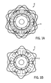
- FIGS. 1A and 1B for example, prior art electrical machines 6 used today across the board in many fields, especially for hybrid applications, are equipped with integral-slot distributed windings 8 that produce a fairly sinusoidal rotating field in the air gap when excited by AC currents.
- FIG. 1A illustrates a 24-slot, overlapping distributed arrangement of windings 8
- FIG. 1B illustrates a 12-slot, overlapping concentrated arrangement of windings 8 as such configurations are known in the art.
- Fractional-slot concentrated windings (sometimes referred to as tooth windings), for example, have been developed as an alternative configuration (see Fig. 3A and 3B , for example).
- Such windings are simpler, easier to manufacture, less expensive, and help improve the machine power density.
- tooth windings introduce increased levels of space harmonics that produce non-sinusoidal rotating fields in the machine air gap. These non-sinusoidal fields generate losses in both the stator and the rotor and hence reduce the machine efficiency.
- the present invention provides a motor drive as defined in claim 1 and a method as defined in claim 12.
- the invention is a directed method and apparatus for exciting an electrical machine with instantaneous non-sinusoidal current waveforms.
- a motor drive having an input connectable to a power source and an output connectable to an input terminal of an electrical machine having a plurality of fractional-slot concentrated windings.
- the motor drive includes an inverter having a plurality of switches therein to control current flow and terminal voltages in the electrical machine and a controller connected to the inverter and programmed to input an initial sinusoidal current demand to the inverter, thereby causing the inverter to output an initial sinusoidal input current.
- the controller is also programmed to receive feedback on an air gap magnetic field in the electrical machine generated by the initial sinusoidal current demand, determine an instantaneous fundamental component and instantaneous harmonic components of the air gap magnetic field, and apply a correction to the instantaneous fundamental component of the air gap magnetic field to generate an ideal fundamental component.
- the controller is further programmed to generate a non-sinusoidal current demand based on the ideal fundamental component and input the non-sinusoidal current demand to the inverter, thereby causing the inverter to output a non-sinusoidal current.
- a method for exciting an electrical machine having a plurality of fractional-slot concentrated windings includes the steps of inputting a test sinusoidal current demand to an inverter and generating an initial sinusoidal current waveform in the inverter in response to the test sinusoidal current demand, the initial sinusoidal current waveform being output to the electrical machine to generate a rotating magnetic field between a rotor and a stator included therein.
- the method also includes the steps of determining a fundamental component and harmonic components of the rotating magnetic field, determining an ideal fundamental component for the air rotating magnetic field from the test sinusoidal current demand and the fundamental component, and determining a desired current waveform based on the ideal fundamental component.
- the method further includes the steps of generating a non-sinusoidal current demand based on the desired current waveform and inputting the non-sinusoidal current demand to the inverter, thereby causing the inverter to output a non-sinusoidal current waveform to the electrical machine to generate a sinusoidal rotating magnetic field.
- a motor drive controller for applying current commands to an inverter to control current flow and terminal voltages in an electrical machine.
- the motor drive controller is configured to input an initial sinusoidal current demand to the inverter, thereby causing the inverter to output an initial sinusoidal input current.
- the motor drive controller is also configured to receive an input signal including data on an instantaneous rotating magnetic field generated in the electrical machine responsive to the initial sinusoidal current demand, determine an instantaneous fundamental component and instantaneous harmonic components of the instantaneous rotating magnetic field, and identify an ideal fundamental component for the rotating magnetic field based on the initial sinusoidal current demand and the instantaneous fundamental component.
- the motor drive controller is further configured to generate an instantaneous non-sinusoidal current demand based on the ideal fundamental component and input the instantaneous non-sinusoidal current demand to the inverter, thereby causing the inverter to output a non-sinusoidal current that causes the electrical machine to generate a rotating magnetic field having the ideal fundamental component.
- Embodiments of the invention are directed to systems and methods for exciting an electrical machine with instantaneous non-sinusoidal current waveforms.
- a control scheme is implemented that processes an initial sinusoidal current command applied to the inverter in order to generate instantaneous non-sinusoidal current commands that will produce rotating air gap fields with only fundamental components and eliminate all field harmonics, thus resulting in the best energy conversion from the stator to the rotor, i.e. high torque at high efficiency.
- Embodiments of the invention are directed to motor drives encompassing a plurality of structures and to a control scheme for operating the motor drives.
- the general structure of an AC motor drive 10 is shown in FIG. 2 according to one embodiment of the invention.
- the motor drive 10 may be configured, for example, as an adjustable speed drive (ASD) designed to receive a three phase AC power input, rectify the AC input, and perform a DC/AC conversion of the rectified segment into a three-phase alternating voltage of variable frequency and amplitude that is supplied to a load.
- ASSD adjustable speed drive
- motor drive 10 may be designed to receive a DC power input and perform a DC/AC conversion of the DC power into a three-phase alternating voltage of variable frequency and amplitude that is supplied to a load.
- the ASD operates according to an exemplary volts-per-hertz characteristic.
- the motor drive provides voltage regulation of ⁇ 1% in steady state with less than 3% total harmonic distortion, ⁇ 0.1 Hz in output frequency, and fast dynamic step load response over a full load range.
- a three-phase AC input 12a-12c is fed to a three-phase rectifier bridge 14.
- the input line impedances are equal in all three phases.
- the rectifier bridge 14 converts the AC power input to a DC power such that a DC bus voltage is present between the rectifier bridge 14 and a switch array 16.
- the bus voltage is smoothed by a DC bus capacitor bank 18.
- the switch array 16 is comprised of a series of IGBT switches 20 and anti-parallel diodes 22 that collectively form an inverter 24.
- the inverter 24 synthesizes AC voltage waveforms for delivery to a load, such as an AC motor 26 according to current demands generated by a motor drive controller 28, as will be explained in greater detail below.
- the controller 28 interfaces to the inverter 24 via current demand signals and sensing of the DC bus voltage and pole currents (by way a voltage sensor 34 for example) such that changes in DC bus voltage can be sensed. These voltage changes can be interpreted as transient load conditions and are used in the generation/input of instantaneous current demands to inverter 24, such that near steady-state load conditions are maintained.
- load 26 is in the form of an electrical machine, such as an electric motor or a generator having a known construction, as shown in FIGS. 3A and 3B .
- the electrical machine 26 may be in the form of any of a permanent magnet machine, an induction machine, a synchronous reluctance machine, and a switched reluctance machine.
- electrical machine 26 includes therein a stator 36 and a rotor 38 which is rotatably fitted in the stator 36.
- the stator 36 has a stator core 40 and windings 42 wound on the stator core 40.
- the stator core 40 has a core main body 44 formed by stacking a large number of annular-shaped thin plates made of electromagnetic steel and insulators (insulating members) 46 provided on axial end surfaces of the core main body 44.
- the stator core 40 is provided with a plurality of teeth 48 at a predetermined pitch along a circumferential direction thereof.
- windings 42 are wound on the respective teeth 48, and thus are in the form of fractional-slot concentrated windings or "tooth windings.”
- Slots 50 are formed between adjacent teeth 48 along the circumferential direction.
- one embodiment of stator 36 includes six slots 50, with non-overlapping windings 42 wound about all teeth 48, according to an embodiment of the invention. As shown in FIG.
- stator 36 includes six slots 50, with non-overlapping windings 42 wound about alternate teeth 48, according to another embodiment of the invention. It is recognized that loads 26 including other arrangements of concentrated windings are envisioned as being usable with embodiments of the present invention, and thus the winding arrangements of FIGS. 3A and 3B are merely exemplary.
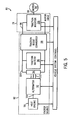
- FIG. 4 a block diagram is shown representative of a control scheme 52 for operating motor drive 10 ( FIG. 2 ) that is implemented, for example, by controller 28 ( FIG. 2 ).
- the control scheme 52 of FIG. 4 performs electronic processing details (EPD) used together with the electrical machine 26 having fractional-slot concentrated stator windings 42 ( FIGS. 3A and 3B ) to achieve high power density, high efficiency, and reduced cost of both the electrical machine 26 and the inverter 24. That is, control scheme 52 is implemented in order to generate instantaneous non-sinusoidal current commands that will produce rotating air gap fields with only fundamental components and eliminate all field harmonics, thus resulting in the best energy conversion from the stator to the rotor, i.e. high torque at high efficiency.
- EPD electronic processing details
- BLOCK 54 of control scheme 52 performs a selective "synchronization time function" operation on a received first input current 56 and received second input current 58.
- the first input current 56 is an initial or test current input that is input into BLOCK 54 from a power source (not shown) and is in the form of a sinusoidal calculated current demand.
- the initial/test sinusoidal current demand is calculated, for example, based on an input from an operator requesting a desired torque to be generated by electrical machine 26.
- second input current 58 is absent.
- the initial/test sinusoidal current demand of first input 56 passes through BLOCK 54 unaffected (i.e., no time synchronization performed on first input 56) to represent the sinusoidal current demand to the inverter 24. Responsive to the initial/test sinusoidal current demand, inverter 24 produces or generates an initial current that is output therefrom.
- the initial output current is passed to BLOCK 60, which functions to adjust an amplitude of the current according to the initial sinusoidal current demand so as to produce a rotating magnetic field (that meets the torque requirement) in the air gap of the electrical machine 26 (i.e., in the air gap between rotor 36 and stator 38, FIGS. 3A and 3B ) that can be easily detected, as will be explained below.
- the adjustment factor added by BLOCK 60 is then stored for later use.
- the current output from BLOCK 60 is applied to the machine terminals of electrical machine 26, which responsive thereto, produces a rotating magnetic field in the air gap.
- the rotating magnetic field generated by electrical machine 26 is detected, for example, by using high temperature Hall probes 62 integrated into electrical machine 26, or alternatively by using search coils (not shown) located preferably at the center of the stator.
- the output of the search coils/Hall probes is transmitted to BLOCK 64 and is received thereby (i.e., received by controller) as feedback on a strength of the air gap magnetic field.
- a fast Fourier transform (FFT) is performed on the air gap magnetic field feedback at BLOCK 64 to determine/analyze the fundamental component and the harmonic components of the air gap rotating field. That is, instantaneous values of the fundamental component and the harmonic components of the air gap rotating field are determined.
- FFT fast Fourier transform
- BLOCK 66 Values for the instantaneous fundamental component and the instantaneous harmonic components of the air gap rotating field determined in BLOCK 64 are passed to BLOCK 66, which acts to eliminate the harmonic components of the air gap magnetic field.
- the fundamental component of the air gap magnetic field is thus isolated and is subsequently passed to BLOCK 68.
- the isolated instantaneous fundamental component of the air gap magnetic field is input to BLOCK 68 along with the first input 56 (i.e., the initial sinusoidal current demand).
- a lookup table is stored in BLOCK 68 that has stored therein a plurality of sinusoidal input current demands and the ideal fundamental component of a rotating magnetic field generated from each of the plurality of sinusoidal input current demands.
- the "ideal" fundamental component of the rotating magnetic field associated with each sinusoidal input current demand is defined in the lookup table as the highest fundamental component generated by input of the sinusoidal input current demand to an electrical machine having sinusoidal windings.
- the isolated instantaneous fundamental component of the air gap magnetic field and the initial sinusoidal current demand of the first input are analyzed/compared to the lookup table in BLOCK 68. More specifically, the instantaneous fundamental component of the air gap magnetic field and the initial sinusoidal current demand are analyzed with respect to the lookup table to determine what current demand need be applied to an electrical machine having sinusoidal windings in order to generate the instantaneous fundamental component of the air gap magnetic field. Based on this determination, a correction is applied to the instantaneous fundamental component of the rotating magnetic field, such that the ideal fundamental component for the needed sinusoidal current demand is realized.
- the ideal fundamental component is input to BLOCK 70. Also in BLOCK 70, the adjustment factor previously applied to the initial sinusoidal current demand in BLOCK 60 is removed, by having an input from BLOCK 60 to BLOCK 70 to cancel the adjustment done earlier. A "true" signal is thus output from BLOCK 70 and received by BLOCK 72. At BLOCK 72, a Laplace transform is performed on the signal from BLOCK 70.
- BLOCK 74 represents the Laplace transfer function of the fractional-slot concentrated winding in the electrical machine.
- the transfer function of BLOCK 74 is obtained between the current input to the electrical machine terminal and the rotating magnetic field as measured by the search coils/Hall probes. This is measured over the full speed range of the electrical machine using standard small signal perturbation techniques, as known in the control industry.
- the Laplace transform of the fractional-slot concentrated windings is between the output of the Hall search coils/Hall probes, which is the fundamental component of the air gap magnetic field, and the input signal, which is the fundamental of the input current demand.
- BLOCK 72 which is the Laplace transfer of the instantaneous air gap magnetic field
- BLOCK 74 which is the transfer function of the fractional-slot concentrated winding.
- BLOCK 76 the inverse Laplace transform is applied to the output of BLOCK 74 to re-construct the exact instantaneous low voltage current waveform that, when applied to the inverter, will produce the desired instantaneous current.
- a desired current waveform for generating the ideal fundamental component of the rotating magnetic field is thus determined from BLOCKS 72, 74, and 76. Based on the desired current waveform, an instantaneous non-sinusoidal current demand is generated that will produce the desired current waveform when applied to the inverter.
- the instantaneous non-sinusoidal current demand generated from BLOCK 76 is sent to BLOCK 54 as second input current 58.
- BLOCK 54 zeroes the sinusoidal first input current 56 and performs a synchronization time function operation on second input current 58 from the power source (not shown), which adjusts the timing of the second input current.
- the adjusted (i.e., instantaneous) non-sinusoidal current demand is then sent to inverter 24, thereby causing the inverter to output a non-sinusoidal current that causes electrical machine 26 to generate a rotating magnetic field having the ideal fundamental component.
- the ideal fundamental component of the rotating magnetic field causes electrical machine 26 to produce high torque with minimum losses, as harmonics are eliminated.
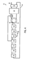
- a motor drive 78 implementing a control scheme/electronic processing as described in FIG. 4 is shown as incorporated into a hybrid electric vehicle (HEV) AC propulsion system 80 that produces tractive effort, according to an embodiment of the invention.
- motor drive 78 receives a DC power or voltage as an input.
- Propulsion system 80 includes motor drive 78, an energy source 82, and a motor 84 configured as an AC motor having fractional-slot concentrated windings, or tooth windings.
- energy source 82 generates a high DC voltage 86.
- Motor drive 78 generates a motor voltage 88 from high DC voltage 86, and motor 84 produces tractive effort from motor voltage 88.
- motor 84 refers to an AC motor capable of producing mechanical power from electrical power including, without limitation, single phase or multiple phase AC motors.
- energy source 82 is configured as a hybrid-electric energy source that comprises a heat engine 90, an alternator 92, a rectifier 94, a traction/energy battery 96, and a traction boost converter 98.
- Traction boost converter 98 is sometimes referred to as bi-directional DC-DC converter, or a bi-directional boost/buck converter that functions to decouple the voltage between the input and the output of the device while efficiently transferring power.
- heat engine 90 generates mechanical power 100 by burning a fuel.
- Alternator 92 generates an alternating voltage 102 from mechanical power 100 and rectifier 94 then rectifies alternating voltage 102 to produce a low DC voltage 104.
- Energy battery 96 stores and delivers energy derived from low DC voltage 104, and traction boost converter 98 boosts low DC voltage 104 to produce high DC voltage 86.
- low and high are relative terms only and imply no particular absolute voltage levels.
- the high DC voltage 86 is transferred to motor drive 78, which includes therein a traction converter 106 (i.e., inverter) that receives high DC voltage 86 and, responsive thereto, generates motor voltage 88 from high DC voltage 86 during motoring operation. Additionally, traction converter 106 generates high DC voltage 86 from motor voltage 88 during braking operation.
- traction converter 106 i.e., inverter
- the high DC voltage 86 is produced from motor voltage 88 and the power flow is from the high voltage side 86 of the bi-directional DC-DC converter 98 to the lower voltage side 104 of the bi-directional DC-DC converter 98 through a "buck" mode of operation.
- motor drive 78 In operation, motor drive 78 generates an initial sinusoidal current demand (i.e., a first input) responsive to a requested torque output of AC motor 84. As set forth in detail with respect to FIG. 4 , motor drive 78 (i.e., a controller in motor drive 78) transmits the initial sinusoidal current demand to traction inverter 106 to produce an initial current for transmission to AC motor 84.
- AC motor generates a rotating magnetic field responsive to the initial sinusoidal current demand, from which motor drive 78 determines fundamental and harmonic components. The harmonic components of the air gap magnetic field are eliminated and motor drive 78 applies a correction to the fundamental component to generate an ideal fundamental component.
- An instantaneous current needed to generate the ideal fundamental component in AC motor 84 and an exact instantaneous low voltage current waveform that when applied to the traction inverter 106 will produce the needed instantaneous current, are determined by motor drive 78.
- motor drive 78 Based on the desired current waveform, motor drive 78 generates an instantaneous non-sinusoidal current demand that will produce the desired current waveform when applied to the traction inverter 106.
- Traction inverter 106 therefore generates motor voltage 88 having a desired current waveform based on the instantaneous non-sinusoidal current demand from motor drive 78.
- motor drive 78 and an accompanying electrical machine are described in FIG. 5 as being incorporated into a HEV AC propulsion system 80 that produces tractive effort, it is recognized that a motor drive configured to implement a technique for exciting an electrical machine with instantaneous non-sinusoidal current waveforms is also applicable to other varied types of electrical machines.
- embodiments of the invention directed to motor drives and motor drive controllers are applicable to electrical machines in numerous industrial, commercial, and transportation industries.
- a technical contribution for the disclosed method and apparatus is that it provides for a controller implemented technique for exciting an electrical machine with instantaneous non-sinusoidal current waveforms.
- a control scheme is implemented that processes an initial sinusoidal current command applied to the inverter in order to generate instantaneous non-sinusoidal current commands that will produce rotating air gap fields with only fundamental components and eliminate all field harmonics, thus resulting in the best energy conversion from the stator to the rotor, i.e. high torque at high efficiency.
- a motor drive having an input connectable to a power source and an output connectable to an input terminal of an electrical machine having a plurality of fractional-slot concentrated windings.
- the motor drive includes an inverter having a plurality of switches therein to control current flow and terminal voltages in the electrical machine and a controller connected to the inverter and programmed to input an initial sinusoidal current demand to the inverter, thereby causing the inverter to output an initial sinusoidal input current.
- the controller is also programmed to receive feedback on an air gap magnetic field in the electrical machine generated by the initial sinusoidal current demand, determine an instantaneous fundamental component and instantaneous harmonic components of the air gap magnetic field, and apply a correction to the instantaneous fundamental component of the air gap magnetic field to generate an ideal fundamental component.
- the controller is further programmed to generate a non-sinusoidal current demand based on the ideal fundamental component and input the non-sinusoidal current demand to the inverter, thereby causing the inverter to output a non-sinusoidal current.
- a method for exciting an electrical machine having a plurality of fractional-slot concentrated windings includes the steps of inputting a test sinusoidal current demand to an inverter and generating an initial sinusoidal current waveform in the inverter in response to the test sinusoidal current demand, the initial sinusoidal current waveform being output to the electrical machine to generate a rotating magnetic field between a rotor and a stator included therein.
- the method also includes the steps of determining a fundamental component and harmonic components of the rotating magnetic field, determining an ideal fundamental component for the air rotating magnetic field from the test sinusoidal current demand and the fundamental component, and determining a desired current waveform based on the ideal fundamental component.
- the method further includes the steps of generating a non-sinusoidal current demand based on the desired current waveform and inputting the non-sinusoidal current demand to the inverter, thereby causing the inverter to output a non-sinusoidal current waveform to the electrical machine to generate a sinusoidal rotating magnetic field.
- a motor drive controller for applying current commands to an inverter to control current flow and terminal voltages in an electrical machine.
- the motor drive controller is configured to input an initial sinusoidal current demand to the inverter, thereby causing the inverter to output an initial sinusoidal input current.
- the motor drive controller is also configured to receive an input signal including data on an instantaneous rotating magnetic field generated in the electrical machine responsive to the initial sinusoidal current demand, determine an instantaneous fundamental component and instantaneous harmonic components of the instantaneous rotating magnetic field, and identify an ideal fundamental component for the rotating magnetic field based on the initial sinusoidal current demand and the instantaneous fundamental component.
- the motor drive controller is further configured to generate an instantaneous non-sinusoidal current demand based on the ideal fundamental component and input the instantaneous non-sinusoidal current demand to the inverter, thereby causing the inverter to output a non-sinusoidal current that causes the electrical machine to generate a rotating magnetic field having the ideal fundamental component.
Landscapes
- Engineering & Computer Science (AREA)
- Power Engineering (AREA)
- Control Of Ac Motors In General (AREA)
Applications Claiming Priority (1)
| Application Number | Priority Date | Filing Date | Title |
|---|---|---|---|
| US12/549,437 US8222855B2 (en) | 2009-08-28 | 2009-08-28 | System and method for non-sinusoidal current waveform excitation of electrical machines |
Publications (3)
| Publication Number | Publication Date |
|---|---|
| EP2290810A2 EP2290810A2 (en) | 2011-03-02 |
| EP2290810A3 EP2290810A3 (en) | 2013-04-24 |
| EP2290810B1 true EP2290810B1 (en) | 2014-06-25 |
Family
ID=43228384
Family Applications (1)
| Application Number | Title | Priority Date | Filing Date |
|---|---|---|---|
| EP10173623.9A Active EP2290810B1 (en) | 2009-08-28 | 2010-08-20 | System and method for non-sinusoidal current waveform excitation of electrical machines |
Country Status (4)
| Country | Link |
|---|---|
| US (1) | US8222855B2 (enExample) |
| EP (1) | EP2290810B1 (enExample) |
| JP (1) | JP5674383B2 (enExample) |
| CN (1) | CN102006006B (enExample) |
Families Citing this family (8)
| Publication number | Priority date | Publication date | Assignee | Title |
|---|---|---|---|---|
| US8901896B2 (en) * | 2010-06-29 | 2014-12-02 | General Electric Company | System and method for non-sinusoidal current waveform excitation of electrical generators |
| DE102011009872A1 (de) * | 2011-01-31 | 2012-08-02 | Lfk-Lenkflugkörpersysteme Gmbh | Verfahren und Vorrichtung zur Modulation der Klemmspannungen eines dreiphasigen Synchronmotors mit nicht-sinusförmiger elektromotorischer Kennlinie sowie dreiphasiger Drehstrommotor |
| GB201109348D0 (en) * | 2011-06-03 | 2011-07-20 | Trw Ltd | Motor control with voltage harmonic shaping |
| CN103997216B (zh) * | 2014-05-23 | 2016-04-27 | 西安交通大学 | 单边桥pwm调制下双向全桥直流变换器的建模方法 |
| US10312845B2 (en) * | 2016-06-14 | 2019-06-04 | Arm Ltd. | Method and apparatus for operating an electric motor |
| US10135377B2 (en) * | 2016-06-14 | 2018-11-20 | Arm Ltd. | Method and apparatus for operating an electric motor |
| EP3648312B1 (de) * | 2018-10-29 | 2022-12-14 | Etel S.A. | Vorgefertigte spule für einen direktantrieb |
| US12261560B2 (en) * | 2023-05-03 | 2025-03-25 | Raytheon Company | Active harmonic filter and reactive power control system for naval ship power systems |
Family Cites Families (13)
| Publication number | Priority date | Publication date | Assignee | Title |
|---|---|---|---|---|
| US4066938A (en) | 1976-10-06 | 1978-01-03 | General Electric Company | Input current modulation to reduce torque pulsations in controlled current inverter drives |
| US4137489A (en) | 1977-07-21 | 1979-01-30 | General Electric Company | Feedback control for reduction of cogging torque in controlled current AC motor drives |
| US4112339A (en) | 1977-07-21 | 1978-09-05 | General Electric Company | Measurement of pulsating torque in a current source inverter motor drive |
| JPS5925592A (ja) * | 1982-08-02 | 1984-02-09 | Toyota Central Res & Dev Lab Inc | インバ−タの制御方法および装置 |
| US5272429A (en) * | 1990-10-01 | 1993-12-21 | Wisconsin Alumni Research Foundation | Air gap flux measurement using stator third harmonic voltage and uses |
| US6262550B1 (en) | 1999-12-17 | 2001-07-17 | General Electric Company | Electrical motor monitoring system and method |
| JP2002078370A (ja) * | 2000-08-25 | 2002-03-15 | Matsushita Electric Ind Co Ltd | インバ一タ装置 |
| US6498451B1 (en) * | 2000-09-06 | 2002-12-24 | Delphi Technologies, Inc. | Torque ripple free electric power steering |
| JP2002315264A (ja) * | 2001-04-11 | 2002-10-25 | Nippon Steel Corp | 電磁機器の騒音、振動低減法 |
| EP1553693B1 (en) * | 2002-10-17 | 2007-12-19 | Denso Corporation | Ac rotary electric machine magnetic noise reduction method, motor control device and ac rotary electric machine using the same |
| DE102004044701B4 (de) * | 2004-09-15 | 2008-01-31 | Siemens Ag | Synchronmaschine |
| US7348705B2 (en) * | 2005-07-21 | 2008-03-25 | Remy Technologies, L.L.C. | Multi-phase fractional slot windings for electric machines having segmented bar-shaped windings |
| FI119748B (fi) * | 2006-12-21 | 2009-02-27 | Kone Corp | Sähkömoottori |
-
2009
- 2009-08-28 US US12/549,437 patent/US8222855B2/en active Active
-
2010
- 2010-08-20 EP EP10173623.9A patent/EP2290810B1/en active Active
- 2010-08-24 JP JP2010186779A patent/JP5674383B2/ja active Active
- 2010-08-27 CN CN2010102728509A patent/CN102006006B/zh active Active
Also Published As
| Publication number | Publication date |
|---|---|
| JP2011050237A (ja) | 2011-03-10 |
| EP2290810A3 (en) | 2013-04-24 |
| US8222855B2 (en) | 2012-07-17 |
| US20110050151A1 (en) | 2011-03-03 |
| CN102006006A (zh) | 2011-04-06 |
| EP2290810A2 (en) | 2011-03-02 |
| JP5674383B2 (ja) | 2015-02-25 |
| CN102006006B (zh) | 2013-10-02 |
Similar Documents
| Publication | Publication Date | Title |
|---|---|---|
| EP2290810B1 (en) | System and method for non-sinusoidal current waveform excitation of electrical machines | |
| US11689136B2 (en) | Dynamically reconfigurable motors and generators and systems with efficiency optimization | |
| EP2432978B1 (en) | Aircraft engine starting/generating system and method of control | |
| US9118271B2 (en) | System and method for non-sinusoidal current waveform excitation of electrical generators | |
| JP7126150B2 (ja) | モータ | |
| EP3081429A1 (en) | Control method for integrated electric drive and charger apparatus for a grid enabled vehicle | |
| EP3006257A1 (en) | Control method for charger apparatus for an electric vehicle | |
| CN112219351A (zh) | 载波频率设定方法、马达驱动系统以及载波频率设定装置 | |
| US20190379312A1 (en) | Rotary electric system | |
| EP3579406A1 (en) | Motor and control device therefor | |
| Yao et al. | Power factor improvement and dynamic performance of an induction machine with a novel concept of a converter-fed rotor | |
| Dajaku et al. | Self-excited synchronous machine with high torque capability at zero speed | |
| Gan et al. | Independent current control of dual parallel SRM drive using a public current sensor | |
| KR101927534B1 (ko) | 회전식 전기 기계의 스테이터의 구성 | |
| CN202856679U (zh) | 航空三级无刷交流同步电机起动过程中的励磁控制装置 | |
| Wu et al. | Influence of PWM excitation on DC winding induced voltage pulsation in wound field switched flux machines | |
| CN103607156B (zh) | 一种混合励磁同步电机功率因数控制方法 | |
| US12199539B2 (en) | Motor control device, electric vehicle, and motor control method | |
| Pötter et al. | A novel brushless excitation system for synchronous machines with a rotating power converter | |
| CN103701260A (zh) | 电机和用于运行这种电机的方法 | |
| CN112671282B (zh) | 三级式同步电机起动过程交直流励磁自然切换方法 | |
| JPH1155991A (ja) | シンクロナスリラクタンスモータの駆動方法 | |
| CN120320648A (zh) | 基于自适应前馈电压补偿的三维弱磁控制方法和系统 | |
| CN114567225A (zh) | 三相电机的充电控制方法、装置、电路及电动车辆 | |
| KR19990048330A (ko) | 전기자동차의 유도전동기 제어장치 및 그 제어방법 |
Legal Events
| Date | Code | Title | Description |
|---|---|---|---|
| PUAI | Public reference made under article 153(3) epc to a published international application that has entered the european phase |
Free format text: ORIGINAL CODE: 0009012 |
|
| AK | Designated contracting states |
Kind code of ref document: A2 Designated state(s): AL AT BE BG CH CY CZ DE DK EE ES FI FR GB GR HR HU IE IS IT LI LT LU LV MC MK MT NL NO PL PT RO SE SI SK SM TR |
|
| AX | Request for extension of the european patent |
Extension state: BA ME RS |
|
| PUAL | Search report despatched |
Free format text: ORIGINAL CODE: 0009013 |
|
| AK | Designated contracting states |
Kind code of ref document: A3 Designated state(s): AL AT BE BG CH CY CZ DE DK EE ES FI FR GB GR HR HU IE IS IT LI LT LU LV MC MK MT NL NO PL PT RO SE SI SK SM TR |
|
| AX | Request for extension of the european patent |
Extension state: BA ME RS |
|
| RIC1 | Information provided on ipc code assigned before grant |
Ipc: B60L 15/20 20060101ALI20130315BHEP Ipc: B60L 15/02 20060101ALI20130315BHEP Ipc: H02P 29/00 20060101AFI20130315BHEP |
|
| 17P | Request for examination filed |
Effective date: 20131024 |
|
| RBV | Designated contracting states (corrected) |
Designated state(s): AL AT BE BG CH CY CZ DE DK EE ES FI FR GB GR HR HU IE IS IT LI LT LU LV MC MK MT NL NO PL PT RO SE SI SK SM TR |
|
| GRAP | Despatch of communication of intention to grant a patent |
Free format text: ORIGINAL CODE: EPIDOSNIGR1 |
|
| INTG | Intention to grant announced |
Effective date: 20140318 |
|
| GRAS | Grant fee paid |
Free format text: ORIGINAL CODE: EPIDOSNIGR3 |
|
| GRAA | (expected) grant |
Free format text: ORIGINAL CODE: 0009210 |
|
| AK | Designated contracting states |
Kind code of ref document: B1 Designated state(s): AL AT BE BG CH CY CZ DE DK EE ES FI FR GB GR HR HU IE IS IT LI LT LU LV MC MK MT NL NO PL PT RO SE SI SK SM TR |
|
| REG | Reference to a national code |
Ref country code: GB Ref legal event code: FG4D |
|
| REG | Reference to a national code |
Ref country code: CH Ref legal event code: EP |
|
| REG | Reference to a national code |
Ref country code: AT Ref legal event code: REF Ref document number: 675213 Country of ref document: AT Kind code of ref document: T Effective date: 20140715 |
|
| REG | Reference to a national code |
Ref country code: IE Ref legal event code: FG4D |
|
| REG | Reference to a national code |
Ref country code: DE Ref legal event code: R096 Ref document number: 602010016938 Country of ref document: DE Effective date: 20140807 |
|
| PG25 | Lapsed in a contracting state [announced via postgrant information from national office to epo] |
Ref country code: GR Free format text: LAPSE BECAUSE OF FAILURE TO SUBMIT A TRANSLATION OF THE DESCRIPTION OR TO PAY THE FEE WITHIN THE PRESCRIBED TIME-LIMIT Effective date: 20140926 Ref country code: CY Free format text: LAPSE BECAUSE OF FAILURE TO SUBMIT A TRANSLATION OF THE DESCRIPTION OR TO PAY THE FEE WITHIN THE PRESCRIBED TIME-LIMIT Effective date: 20140625 Ref country code: NO Free format text: LAPSE BECAUSE OF FAILURE TO SUBMIT A TRANSLATION OF THE DESCRIPTION OR TO PAY THE FEE WITHIN THE PRESCRIBED TIME-LIMIT Effective date: 20140925 Ref country code: LT Free format text: LAPSE BECAUSE OF FAILURE TO SUBMIT A TRANSLATION OF THE DESCRIPTION OR TO PAY THE FEE WITHIN THE PRESCRIBED TIME-LIMIT Effective date: 20140625 |
|
| REG | Reference to a national code |
Ref country code: AT Ref legal event code: MK05 Ref document number: 675213 Country of ref document: AT Kind code of ref document: T Effective date: 20140625 |
|
| REG | Reference to a national code |
Ref country code: NL Ref legal event code: VDEP Effective date: 20140625 |
|
| REG | Reference to a national code |
Ref country code: LT Ref legal event code: MG4D |
|
| PG25 | Lapsed in a contracting state [announced via postgrant information from national office to epo] |
Ref country code: HR Free format text: LAPSE BECAUSE OF FAILURE TO SUBMIT A TRANSLATION OF THE DESCRIPTION OR TO PAY THE FEE WITHIN THE PRESCRIBED TIME-LIMIT Effective date: 20140625 Ref country code: LV Free format text: LAPSE BECAUSE OF FAILURE TO SUBMIT A TRANSLATION OF THE DESCRIPTION OR TO PAY THE FEE WITHIN THE PRESCRIBED TIME-LIMIT Effective date: 20140625 Ref country code: SE Free format text: LAPSE BECAUSE OF FAILURE TO SUBMIT A TRANSLATION OF THE DESCRIPTION OR TO PAY THE FEE WITHIN THE PRESCRIBED TIME-LIMIT Effective date: 20140625 |
|
| PG25 | Lapsed in a contracting state [announced via postgrant information from national office to epo] |
Ref country code: PT Free format text: LAPSE BECAUSE OF FAILURE TO SUBMIT A TRANSLATION OF THE DESCRIPTION OR TO PAY THE FEE WITHIN THE PRESCRIBED TIME-LIMIT Effective date: 20141027 Ref country code: SK Free format text: LAPSE BECAUSE OF FAILURE TO SUBMIT A TRANSLATION OF THE DESCRIPTION OR TO PAY THE FEE WITHIN THE PRESCRIBED TIME-LIMIT Effective date: 20140625 Ref country code: ES Free format text: LAPSE BECAUSE OF FAILURE TO SUBMIT A TRANSLATION OF THE DESCRIPTION OR TO PAY THE FEE WITHIN THE PRESCRIBED TIME-LIMIT Effective date: 20140625 Ref country code: EE Free format text: LAPSE BECAUSE OF FAILURE TO SUBMIT A TRANSLATION OF THE DESCRIPTION OR TO PAY THE FEE WITHIN THE PRESCRIBED TIME-LIMIT Effective date: 20140625 Ref country code: CZ Free format text: LAPSE BECAUSE OF FAILURE TO SUBMIT A TRANSLATION OF THE DESCRIPTION OR TO PAY THE FEE WITHIN THE PRESCRIBED TIME-LIMIT Effective date: 20140625 Ref country code: RO Free format text: LAPSE BECAUSE OF FAILURE TO SUBMIT A TRANSLATION OF THE DESCRIPTION OR TO PAY THE FEE WITHIN THE PRESCRIBED TIME-LIMIT Effective date: 20140625 |
|
| PG25 | Lapsed in a contracting state [announced via postgrant information from national office to epo] |
Ref country code: PL Free format text: LAPSE BECAUSE OF FAILURE TO SUBMIT A TRANSLATION OF THE DESCRIPTION OR TO PAY THE FEE WITHIN THE PRESCRIBED TIME-LIMIT Effective date: 20140625 Ref country code: IS Free format text: LAPSE BECAUSE OF FAILURE TO SUBMIT A TRANSLATION OF THE DESCRIPTION OR TO PAY THE FEE WITHIN THE PRESCRIBED TIME-LIMIT Effective date: 20141025 Ref country code: NL Free format text: LAPSE BECAUSE OF FAILURE TO SUBMIT A TRANSLATION OF THE DESCRIPTION OR TO PAY THE FEE WITHIN THE PRESCRIBED TIME-LIMIT Effective date: 20140625 Ref country code: AT Free format text: LAPSE BECAUSE OF FAILURE TO SUBMIT A TRANSLATION OF THE DESCRIPTION OR TO PAY THE FEE WITHIN THE PRESCRIBED TIME-LIMIT Effective date: 20140625 |
|
| REG | Reference to a national code |
Ref country code: DE Ref legal event code: R097 Ref document number: 602010016938 Country of ref document: DE |
|
| PG25 | Lapsed in a contracting state [announced via postgrant information from national office to epo] |
Ref country code: MC Free format text: LAPSE BECAUSE OF FAILURE TO SUBMIT A TRANSLATION OF THE DESCRIPTION OR TO PAY THE FEE WITHIN THE PRESCRIBED TIME-LIMIT Effective date: 20140625 Ref country code: LU Free format text: LAPSE BECAUSE OF FAILURE TO SUBMIT A TRANSLATION OF THE DESCRIPTION OR TO PAY THE FEE WITHIN THE PRESCRIBED TIME-LIMIT Effective date: 20140820 |
|
| REG | Reference to a national code |
Ref country code: CH Ref legal event code: PL |
|
| PG25 | Lapsed in a contracting state [announced via postgrant information from national office to epo] |
Ref country code: LI Free format text: LAPSE BECAUSE OF NON-PAYMENT OF DUE FEES Effective date: 20140831 Ref country code: CH Free format text: LAPSE BECAUSE OF NON-PAYMENT OF DUE FEES Effective date: 20140831 Ref country code: FI Free format text: LAPSE BECAUSE OF NON-PAYMENT OF DUE FEES Effective date: 20140820 Ref country code: BE Free format text: LAPSE BECAUSE OF NON-PAYMENT OF DUE FEES Effective date: 20140831 Ref country code: IT Free format text: LAPSE BECAUSE OF FAILURE TO SUBMIT A TRANSLATION OF THE DESCRIPTION OR TO PAY THE FEE WITHIN THE PRESCRIBED TIME-LIMIT Effective date: 20140625 Ref country code: DK Free format text: LAPSE BECAUSE OF FAILURE TO SUBMIT A TRANSLATION OF THE DESCRIPTION OR TO PAY THE FEE WITHIN THE PRESCRIBED TIME-LIMIT Effective date: 20140625 |
|
| PLBE | No opposition filed within time limit |
Free format text: ORIGINAL CODE: 0009261 |
|
| STAA | Information on the status of an ep patent application or granted ep patent |
Free format text: STATUS: NO OPPOSITION FILED WITHIN TIME LIMIT |
|
| REG | Reference to a national code |
Ref country code: IE Ref legal event code: MM4A |
|
| 26N | No opposition filed |
Effective date: 20150326 |
|
| PG25 | Lapsed in a contracting state [announced via postgrant information from national office to epo] |
Ref country code: BE Free format text: LAPSE BECAUSE OF FAILURE TO SUBMIT A TRANSLATION OF THE DESCRIPTION OR TO PAY THE FEE WITHIN THE PRESCRIBED TIME-LIMIT Effective date: 20140625 |
|
| PG25 | Lapsed in a contracting state [announced via postgrant information from national office to epo] |
Ref country code: IE Free format text: LAPSE BECAUSE OF NON-PAYMENT OF DUE FEES Effective date: 20140820 |
|
| PG25 | Lapsed in a contracting state [announced via postgrant information from national office to epo] |
Ref country code: SI Free format text: LAPSE BECAUSE OF FAILURE TO SUBMIT A TRANSLATION OF THE DESCRIPTION OR TO PAY THE FEE WITHIN THE PRESCRIBED TIME-LIMIT Effective date: 20140625 |
|
| PG25 | Lapsed in a contracting state [announced via postgrant information from national office to epo] |
Ref country code: SM Free format text: LAPSE BECAUSE OF FAILURE TO SUBMIT A TRANSLATION OF THE DESCRIPTION OR TO PAY THE FEE WITHIN THE PRESCRIBED TIME-LIMIT Effective date: 20140625 |
|
| PG25 | Lapsed in a contracting state [announced via postgrant information from national office to epo] |
Ref country code: BG Free format text: LAPSE BECAUSE OF FAILURE TO SUBMIT A TRANSLATION OF THE DESCRIPTION OR TO PAY THE FEE WITHIN THE PRESCRIBED TIME-LIMIT Effective date: 20140625 Ref country code: MT Free format text: LAPSE BECAUSE OF FAILURE TO SUBMIT A TRANSLATION OF THE DESCRIPTION OR TO PAY THE FEE WITHIN THE PRESCRIBED TIME-LIMIT Effective date: 20140625 |
|
| PG25 | Lapsed in a contracting state [announced via postgrant information from national office to epo] |
Ref country code: HU Free format text: LAPSE BECAUSE OF FAILURE TO SUBMIT A TRANSLATION OF THE DESCRIPTION OR TO PAY THE FEE WITHIN THE PRESCRIBED TIME-LIMIT; INVALID AB INITIO Effective date: 20100820 Ref country code: TR Free format text: LAPSE BECAUSE OF FAILURE TO SUBMIT A TRANSLATION OF THE DESCRIPTION OR TO PAY THE FEE WITHIN THE PRESCRIBED TIME-LIMIT Effective date: 20140625 |
|
| REG | Reference to a national code |
Ref country code: FR Ref legal event code: PLFP Year of fee payment: 7 |
|
| REG | Reference to a national code |
Ref country code: FR Ref legal event code: PLFP Year of fee payment: 8 |
|
| PG25 | Lapsed in a contracting state [announced via postgrant information from national office to epo] |
Ref country code: MK Free format text: LAPSE BECAUSE OF FAILURE TO SUBMIT A TRANSLATION OF THE DESCRIPTION OR TO PAY THE FEE WITHIN THE PRESCRIBED TIME-LIMIT Effective date: 20140625 |
|
| REG | Reference to a national code |
Ref country code: FR Ref legal event code: PLFP Year of fee payment: 9 |
|
| PG25 | Lapsed in a contracting state [announced via postgrant information from national office to epo] |
Ref country code: AL Free format text: LAPSE BECAUSE OF FAILURE TO SUBMIT A TRANSLATION OF THE DESCRIPTION OR TO PAY THE FEE WITHIN THE PRESCRIBED TIME-LIMIT Effective date: 20140625 |
|
| P01 | Opt-out of the competence of the unified patent court (upc) registered |
Effective date: 20230528 |
|
| PGFP | Annual fee paid to national office [announced via postgrant information from national office to epo] |
Ref country code: DE Payment date: 20240723 Year of fee payment: 15 |
|
| PGFP | Annual fee paid to national office [announced via postgrant information from national office to epo] |
Ref country code: GB Payment date: 20240723 Year of fee payment: 15 |
|
| PGFP | Annual fee paid to national office [announced via postgrant information from national office to epo] |
Ref country code: FR Payment date: 20240723 Year of fee payment: 15 |
|
| REG | Reference to a national code |
Ref country code: DE Ref legal event code: R119 Ref document number: 602010016938 Country of ref document: DE |