EP2290697B1 - Verfahren zur Herstellung einer Hochspannungshalbleiteranordnung mit Spaltenstrukturen - Google Patents
Verfahren zur Herstellung einer Hochspannungshalbleiteranordnung mit Spaltenstrukturen Download PDFInfo
- Publication number
- EP2290697B1 EP2290697B1 EP10174803.6A EP10174803A EP2290697B1 EP 2290697 B1 EP2290697 B1 EP 2290697B1 EP 10174803 A EP10174803 A EP 10174803A EP 2290697 B1 EP2290697 B1 EP 2290697B1
- Authority
- EP
- European Patent Office
- Prior art keywords
- epitaxial layer
- epitaxial
- layer
- deep trench
- column structures
- Prior art date
- Legal status (The legal status is an assumption and is not a legal conclusion. Google has not performed a legal analysis and makes no representation as to the accuracy of the status listed.)
- Active
Links
Images
Classifications
-
- H—ELECTRICITY
- H10—SEMICONDUCTOR DEVICES; ELECTRIC SOLID-STATE DEVICES NOT OTHERWISE PROVIDED FOR
- H10D—INORGANIC ELECTRIC SEMICONDUCTOR DEVICES
- H10D30/00—Field-effect transistors [FET]
- H10D30/60—Insulated-gate field-effect transistors [IGFET]
- H10D30/64—Double-diffused metal-oxide semiconductor [DMOS] FETs
- H10D30/66—Vertical DMOS [VDMOS] FETs
-
- H—ELECTRICITY
- H10—SEMICONDUCTOR DEVICES; ELECTRIC SOLID-STATE DEVICES NOT OTHERWISE PROVIDED FOR
- H10D—INORGANIC ELECTRIC SEMICONDUCTOR DEVICES
- H10D12/00—Bipolar devices controlled by the field effect, e.g. insulated-gate bipolar transistors [IGBT]
- H10D12/411—Insulated-gate bipolar transistors [IGBT]
- H10D12/441—Vertical IGBTs
-
- H—ELECTRICITY
- H10—SEMICONDUCTOR DEVICES; ELECTRIC SOLID-STATE DEVICES NOT OTHERWISE PROVIDED FOR
- H10D—INORGANIC ELECTRIC SEMICONDUCTOR DEVICES
- H10D30/00—Field-effect transistors [FET]
- H10D30/01—Manufacture or treatment
- H10D30/021—Manufacture or treatment of FETs having insulated gates [IGFET]
- H10D30/028—Manufacture or treatment of FETs having insulated gates [IGFET] of double-diffused metal oxide semiconductor [DMOS] FETs
- H10D30/0291—Manufacture or treatment of FETs having insulated gates [IGFET] of double-diffused metal oxide semiconductor [DMOS] FETs of vertical DMOS [VDMOS] FETs
-
- H—ELECTRICITY
- H10—SEMICONDUCTOR DEVICES; ELECTRIC SOLID-STATE DEVICES NOT OTHERWISE PROVIDED FOR
- H10D—INORGANIC ELECTRIC SEMICONDUCTOR DEVICES
- H10D30/00—Field-effect transistors [FET]
- H10D30/60—Insulated-gate field-effect transistors [IGFET]
- H10D30/64—Double-diffused metal-oxide semiconductor [DMOS] FETs
- H10D30/66—Vertical DMOS [VDMOS] FETs
- H10D30/665—Vertical DMOS [VDMOS] FETs having edge termination structures
-
- H—ELECTRICITY
- H10—SEMICONDUCTOR DEVICES; ELECTRIC SOLID-STATE DEVICES NOT OTHERWISE PROVIDED FOR
- H10D—INORGANIC ELECTRIC SEMICONDUCTOR DEVICES
- H10D62/00—Semiconductor bodies, or regions thereof, of devices having potential barriers
- H10D62/01—Manufacture or treatment
- H10D62/051—Forming charge compensation regions, e.g. superjunctions
- H10D62/058—Forming charge compensation regions, e.g. superjunctions by using trenches, e.g. implanting into sidewalls of trenches or refilling trenches
-
- H—ELECTRICITY
- H10—SEMICONDUCTOR DEVICES; ELECTRIC SOLID-STATE DEVICES NOT OTHERWISE PROVIDED FOR
- H10D—INORGANIC ELECTRIC SEMICONDUCTOR DEVICES
- H10D62/00—Semiconductor bodies, or regions thereof, of devices having potential barriers
- H10D62/10—Shapes, relative sizes or dispositions of the regions of the semiconductor bodies; Shapes of the semiconductor bodies
- H10D62/102—Constructional design considerations for preventing surface leakage or controlling electric field concentration
- H10D62/103—Constructional design considerations for preventing surface leakage or controlling electric field concentration for increasing or controlling the breakdown voltage of reverse-biased devices
- H10D62/105—Constructional design considerations for preventing surface leakage or controlling electric field concentration for increasing or controlling the breakdown voltage of reverse-biased devices by having particular doping profiles, shapes or arrangements of PN junctions; by having supplementary regions, e.g. junction termination extension [JTE]
- H10D62/109—Reduced surface field [RESURF] PN junction structures
- H10D62/111—Multiple RESURF structures, e.g. double RESURF or 3D-RESURF structures
-
- H—ELECTRICITY
- H10—SEMICONDUCTOR DEVICES; ELECTRIC SOLID-STATE DEVICES NOT OTHERWISE PROVIDED FOR
- H10D—INORGANIC ELECTRIC SEMICONDUCTOR DEVICES
- H10D62/00—Semiconductor bodies, or regions thereof, of devices having potential barriers
- H10D62/10—Shapes, relative sizes or dispositions of the regions of the semiconductor bodies; Shapes of the semiconductor bodies
- H10D62/113—Isolations within a component, i.e. internal isolations
- H10D62/115—Dielectric isolations, e.g. air gaps
-
- H—ELECTRICITY
- H10—SEMICONDUCTOR DEVICES; ELECTRIC SOLID-STATE DEVICES NOT OTHERWISE PROVIDED FOR
- H10D—INORGANIC ELECTRIC SEMICONDUCTOR DEVICES
- H10D62/00—Semiconductor bodies, or regions thereof, of devices having potential barriers
- H10D62/10—Shapes, relative sizes or dispositions of the regions of the semiconductor bodies; Shapes of the semiconductor bodies
- H10D62/13—Semiconductor regions connected to electrodes carrying current to be rectified, amplified or switched, e.g. source or drain regions
- H10D62/149—Source or drain regions of field-effect devices
- H10D62/151—Source or drain regions of field-effect devices of IGFETs
- H10D62/152—Source regions of DMOS transistors
- H10D62/153—Impurity concentrations or distributions
-
- H—ELECTRICITY
- H10—SEMICONDUCTOR DEVICES; ELECTRIC SOLID-STATE DEVICES NOT OTHERWISE PROVIDED FOR
- H10D—INORGANIC ELECTRIC SEMICONDUCTOR DEVICES
- H10D62/00—Semiconductor bodies, or regions thereof, of devices having potential barriers
- H10D62/10—Shapes, relative sizes or dispositions of the regions of the semiconductor bodies; Shapes of the semiconductor bodies
- H10D62/17—Semiconductor regions connected to electrodes not carrying current to be rectified, amplified or switched, e.g. channel regions
- H10D62/393—Body regions of DMOS transistors or IGBTs
-
- H—ELECTRICITY
- H10—SEMICONDUCTOR DEVICES; ELECTRIC SOLID-STATE DEVICES NOT OTHERWISE PROVIDED FOR
- H10D—INORGANIC ELECTRIC SEMICONDUCTOR DEVICES
- H10D84/00—Integrated devices formed in or on semiconductor substrates that comprise only semiconducting layers, e.g. on Si wafers or on GaAs-on-Si wafers
- H10D84/80—Integrated devices formed in or on semiconductor substrates that comprise only semiconducting layers, e.g. on Si wafers or on GaAs-on-Si wafers characterised by the integration of at least one component covered by groups H10D12/00 or H10D30/00, e.g. integration of IGFETs
- H10D84/82—Integrated devices formed in or on semiconductor substrates that comprise only semiconducting layers, e.g. on Si wafers or on GaAs-on-Si wafers characterised by the integration of at least one component covered by groups H10D12/00 or H10D30/00, e.g. integration of IGFETs of only field-effect components
- H10D84/83—Integrated devices formed in or on semiconductor substrates that comprise only semiconducting layers, e.g. on Si wafers or on GaAs-on-Si wafers characterised by the integration of at least one component covered by groups H10D12/00 or H10D30/00, e.g. integration of IGFETs of only field-effect components of only insulated-gate FETs [IGFET]
-
- H—ELECTRICITY
- H10—SEMICONDUCTOR DEVICES; ELECTRIC SOLID-STATE DEVICES NOT OTHERWISE PROVIDED FOR
- H10D—INORGANIC ELECTRIC SEMICONDUCTOR DEVICES
- H10D64/00—Electrodes of devices having potential barriers
- H10D64/20—Electrodes characterised by their shapes, relative sizes or dispositions
- H10D64/23—Electrodes carrying the current to be rectified, amplified, oscillated or switched, e.g. sources, drains, anodes or cathodes
- H10D64/251—Source or drain electrodes for field-effect devices
- H10D64/256—Source or drain electrodes for field-effect devices for lateral devices wherein the source or drain electrodes are recessed in semiconductor bodies
Definitions
- the present invention relates to a process for manufacturing a structure for a high voltage device, the process being of the type which comprises the steps of:
- the invention particularly, but not exclusively, relates to a vertical conduction MISFET device which is driven through a gate dielectric and the following description is made with reference to this field of application for convenience of explanation only.
- the approach having the best compromise between breakdown voltage and on resistance is the so called SuperJunction approach, which provides for realising a plurality of three-dimensional structures (3D) as drain structures.
- 3D three-dimensional structures
- Different manufacturing methods of these three-dimensional drain structures are aimed to realise a structure integrating columns or column structures, in particular having a first conductivity type, for instance of the p type, able to counterbalance the opposite charge, in particular of the opposite conductivity type, for instance the n type, of the drain layer wherein said column structures are realised, in particular in the portion of said layer extending between subsequent pairs of column structures.
- MD Multi Drain
- the devices disclosed in these documents substantially comprise, within a drain epitaxial layer, of a first conductivity type, charge balanced column structures, having a second conductivity type, opposed than the first type.
- the column structures are realised with a dopant concentration which is substantially equal and opposite to the dopant concentration of the drain layer, so as to obtain a substantial charge balance which allows to obtain high breakdown voltages.
- a drain layer which has a high dopant concentration devices are realised which have a low on resistance and thus reduced conduction losses.
- making column structures comprises a sequence of steps of growing epitaxial layers of the first conductivity type, for instance of the N type, each step being followed by a dopant implantation of the second conductivity type, for instance of the P type.
- Regions of the P type being so implanted are in particular realised so as to be stacked up in the depth development sense of the drain epitaxial layer wherein they are made and are subjected to a following diffusion process of the dopant atoms, in such a way to originate uniform column structures.
- drain epitaxial layer in contact with the column structures, active regions of the high voltage device are realised, in particular body wells, the column structures thus providing extensions of said body wells inside the drain layer.
- Multi Drain devices so realised are characterised by combining a high cut-off voltage with reduced losses thanks to the charge balance between a conduction region, namely the drain region between the columns and the column structures extending into the drain layer, which allow to increase the concentration of such a conduction region obtaining a strong reduction of conduction losses.
- the known solutions to realise Multi Drain devices comprise a high number of process steps, thus turning out to be difficult to implement. Moreover, it often occurs that the dopant profile in the conduction region is not constant.
- the technical problem underlying the present invention is that of manufacturing a structure for a high voltage device having structural and functional characteristics which allow to overcome the limits and drawbacks which still affect the devices realised according to the prior art.
- the solution idea underlying the present invention is that of manufacturing a structure for a high voltage device through a superjunction structure characterized in that it is obtained by partially filling a deep trench having a high aspect ratio, namely having a ratio between width and height less than 3/20, with an epitaxial layer doped in opposition with the preexisting semiconductor layer thus forming the column structures.
- the quantity of dopant being in the epitaxial layer would be the one counterbalancing the dopant being in the neighbouring conduction areas, i.e. the epitaxial layer 3 outside the column structures 4.
- the structure is also characterized in that it further comprises a dielectric layer able to completely fill said deep trench, being partially filled by said epitaxial layer.
- the column structures are structures of the drain area and turn out to have a same periodicity of the active surface areas, being wells realising body areas, each drain column structure being "coupled" to a corresponding body well.
- said epitaxial growing step within said at least one deep trench could grow said silicon layer at least on the walls and on the bottom of said at least one deep trench thus realising an U-shaped external portion of said at least one respective column structure
- said epitaxial growing steps of said epitaxial layer on said semiconductor substrate and of said epitaxial layer within said at least one deep trench could be realised with a low thermal budget and with a process maximum temperature less than 1100°C.
- said epitaxial growing steps could realise said epitaxial layer within said at least one deep trench with a dopant concentration comprised between 1e15 and 1e17 at/cm3, preferably 1e16 at/cm3, and said epitaxial layer on said semiconductor substrate with a dopant concentration comprised between 5e14 and 5e16 at/cm3, preferably 5e15.
- the process could comprise a step of realising a first active area of said structure by forming a plurality of said at least one column structures and could comprise a step of realising, in an active surface area of said structure, at least one second active area which has at least one zone in contact with said first active area.
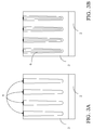
- the structure 1 for a high voltage device comprises a semiconductor substrate 2 covered by an epitaxial layer 3, having a first conductivity type, in particular N type.
- the structure 1 for a high voltage device further comprises an active surface area 5, wherein the active areas of the high voltage device are realised, as will be clarified in the following description.
- Each of the column structures 4 comprises an external portion 6, in particular an epitaxial silicon layer being suitably doped, as well as a filling portion 7, in particular a dielectric layer, such as an oxide, being deposited inside the respective column structure 4 for completely filling it.
- the epitaxial silicon layer of the external portion 6 is doped and has a second conductivity type, in particular the P type.
- the charge which is epitaxially inserted in order to realise the external portion 6 is such as to counterbalance the charge being in the epitaxial layer 3 outside the column structures 4.
- the epitaxial layer, which realises the external portion 6 is on the walls and on the bottom of the corresponding column structure 4, which is realised, as will be clarified in the following description, starting from a trench being dug in the epitaxial layer 3, in particular a deep trench having a high aspect ratio, i.e. a low ratio between width and height, namely less than 3/20.
- a high voltage device is realised, in a conventional manner, of the type comprising at least an active area 8.
- the column structures 4 have respective coupling zones 12 with the active areas 8, having a same periodicity thereof.
- the structure 1 for a high voltage device realised according to the process of the invention comprises column structures 4 in turn realised by a U-shaped zone of semiconductor material, i.e. the external portion 6 of the epitaxial silicon, being suitably doped with a dopand of an opposite type with respect to the one of the neighbouring semiconductor material, i.e. the epitaxial layer 3 outside the column structures 4, this U-shaped external portion 6 being in turn filled by a dielectric layer to form the filling portion 7.
- the charge quantity being in the epitaxial silicon layer of the U-shaped external portion 6 of the column structures 4 is such that a balance of the charge is obtained with respect to the epitaxial layer 3 outside the column structures 4 themselves.
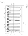
- the MOS transistor comprises a drain epitaxial layer 3 being provided with a plurality of column structures 4 and an active surface area 5 wherein a plurality of body wells 8 are realised, having the second conductivity type, in particular the P type, inside which a corresponding plurality of source wells 9, of the first conductivity type, in particular the N type, is realised.
- the high voltage MOS device of the example of Figure 1 is completed by realising a plurality of gate structures 10, being realised between consecutive pairs of column structures 4, above a channel region, being defined in the drain epitaxial layer 3 between the body wells 8 and in contact with the source wells 9.
- the structure 1 for a high voltage device further comprises a covering or capping layer 11, being realised above the whole high voltage device and in particular covering the gate structures 10.
- the structure 1 for a high voltage device could be provided, in a known manner, with surface contact structures of microtrench or conventional type.
- the gate structures 10 could be of the planar type or of the trench gate type.
- the drain column structures 4, having a same periodicity than the body wells 8, have respective coupling zones 12 with the body wells 8 themselves.
- each of the column structures 4 comprises a pair of coupling zones 12 with the body wells 8 which bounds it at the upper side.
- each of the column structures 4 has a width Lc between 1,5 and 4 ⁇ m, preferably 2 ⁇ m and a height Hc between 10 and 70 ⁇ m, preferably 30 ⁇ m, thus defining a maximum value of aspect ratio of the deep trench which constitutes the column structures 4 equal to 3/20.
- the epitaxial layer which realises the external portion 6 has a dopant concentration between 1e15 and 1e17, preferably 1e16 at/cm3, while the drain epitaxial layer 3 has a dopant concentration between 5e14 and 5e16, preferably 5e15.
- the column structures 4 have a distance Dc between 2 ⁇ m and 8 ⁇ m, preferably 4 ⁇ m, and a distance Dcc between the symmetry axis of the column structures 4 between 2.5 ⁇ m and 12 ⁇ m, preferably 6 ⁇ m.
- the structure 1 for a high voltage device realised according to the process of the invention realises a 600V device.
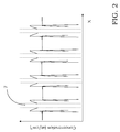
- the dopant concentration along the column structures 4 of an embodiment of the structure 1 for a high voltage device is shown in Figure 2 , X being the longitudinal development axis of the structure 1 itself, as also indicated in Figure 1 .
- the charge epitaxially introduced into the epitaxial layer which realises the U-shaped external portion 6 of the column structures 4 is such that it counterbalances the charge being in the epitaxial layer 3 outside the column structures 4 themselves, the filling portion 7 of such column structures 4 being instead realised by an oxide.
- the dopant in the epitaxial layer forming the U-shaped external portion 6 of the column structures 4 is not constant, but it advantageously has a peak in correspondence with the interface with the epitaxial layer 3 outside the column structures 4 themselves.
- the manufacturing process of the structure 1 for a high voltage device turns out to be well controlled since it is able to guarantee the charge balance between the U-shaped external portion 6 of the column structures 4 and the epitaxial layer 3 outside them (i.e. between the N zone and the P zone) without needing an extremely fine control of the thickness of the silicon epitaxial layer as grown in order to realise the U-shaped external portion 6.
- changes into the thickness of the external portion 6 cause little changes on the total charge amount being contained into the silicon epitaxial layer of such external portion 6 thus making easier the process industrialisation.
- a high voltage device different from a MOS transistor such as for example a diode or an IGBT device.
- the structure 1 for a high voltage device realised according to the process of the invention as comprising a first active area being realised by the column structures 4 and a second active area 8 and having at least one coupling zone 12 which the first active area 4.
- the second active area is "coupled" in correspondence with the coupling zone 12 to a conductive portion of the first active area, in particular of the column structures.
- the first active area is the drain area while the second one is the body area. It is obvious for a technical expert in the field that, in the case for instance of a diode, such first and second active areas would be the cathode and anode areas.
- the second active area is "coupled" in correspondence with the coupling zone 12 to the external portion 6 of the column structure 4, being a conductive portion of the first active area.
- the present invention relates to a process for manufacturing a structure 1 for a high voltage device of the above indicated type.
- This manufacturing process comprises the steps as defined in claim 1.
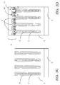
- the process of the invention further comprises the step of epitaxially growing within the trench 4 a silicon layer 6, according to an embodiment being placed at least on the walls and on the bottom of the trench 4 so as to realise an external portion of a column structure 4 being thus formed into the epitaxial layer 3.
- the epitaxial layer 6 having been grown to form such an external portion is doped with a dopant of a second type and in such a way that the dopant charge being epitaxially introduced counterbalances the charge of the dopant of the first type of the epitaxial layer 3 surrounding the trench 4, as schematically shown in Figure 3B .
- Said epitaxial growing step advantageously grows an epitaxial layer 6 having a dopant concentration with a variable concentration profile having a maximum near an interface with the epitaxial layer 3.
- the steps of epitaxially growing the drain epitaxial layer 3 and the epitaxial layer 6 of the external portion of the column structures are realised with a limited thermal budget and a maximum process temperature less than 1100°C.
- the process according to the invention turns out to be compatible also with big sized wafers (for instance of 8" or 12") and it is possible to minimize the transition zone between the column structures 4 and the conduction zones, i.e. the portions of the drain epitaxial layer 3 outside said column structures 4.
- a process having a low thermal budget is used in order to keep almost unaltered the dopant distribution inside the epitaxial layer 3 having been grown inside the trench 4 which makes the column structures.
- the epitaxial growing steps realising the epitaxial layer 6 with a dopant concentration between 1e15 and 1e17 at/cm3, preferably 1e16 at/cm3, and a drain epitaxial layer 3 with a dopant concentration between 5e14 and 5e 16 at/cm3, preferably 5e15 at/cm3.
- the process comprises a filling step of the trench 4 by means of a filling dielectric layer 7, in particular an oxide, in order to realise a filling portion of the column structure 4, as schematically shown in Figure 3C .
- This filling step by means of the filling dielectric layer 7 completely fills the trench 4, guaranteeing the absence into the same, and thus into the column structure 4 so realized, of voids.
- the process then comprises a step of realising, in an active surface area 5 of the structure 1, a high voltage device comprising at least an active area.
- the high voltage device is a MOS transistor of the Multi Drain type comprising a drain area being realised by the epitaxial layer 3 and the column structures 4 and comprising source wells 9 being realised into body wells 8, these latter having been advantageously realised in contact with the column structures 4 in correspondence with coupling zones 12, as well as gate structures 10 being realized over channel regions being defined into the epitaxial layer 3 between the body wells 8 and in contact with the source wells 9, as schematically shown in Figure 3D .
- the charge balance being realised by the epitaxial layer 6 of the external portion of the column structures 4 with respect to the epitaxial layer 3 which surrounds them, allows to obtain a constant dopant profile in the conduction zone, the extension of the voltage class of the high voltage device so obtained being thus easier.
- the use of an epitaxial growing step of the layer 6 allows to eliminate every problem of implant angle tied to the high aspect ratio of the trench 4, with a better doping control of the external portion 6 of the column structures 4.
Landscapes
- Metal-Oxide And Bipolar Metal-Oxide Semiconductor Integrated Circuits (AREA)
- Insulated Gate Type Field-Effect Transistor (AREA)
- Chemical & Material Sciences (AREA)
- Composite Materials (AREA)
Claims (5)
- Verfahren zum Herstellen einer Struktur (1) für eine Hochspannungsvorrichtung, wobei das Verfahren derart gestaltet ist, dass es die folgenden Schritte beinhaltet:- Bereitstellen eines Halbleitersubstrats (2) mit einem ersten Leitfähigkeitstyp;- epitaktisches Aufwachsen einer Epitaxieschicht (3) mit dem ersten Leitfähigkeitstyp auf dem Halbleitersubstrat (2); und- Bereitstellen mindestens eines tiefen Grabens in der Epitaxieschicht (3), der ein Verhältnis von Breite zu Höhe von weniger als 3/20 hat, um mindestens eine entsprechende Spaltenstruktur (4) bereitzustellen, die den mindestens einen tiefen Graben in der Epitaxieschicht (3) aufweist;wobei das Verfahren ferner beinhaltet:- einen Schritt des epitaktischen Aufwachsens einer Siliziumschicht der mindestens einen entsprechenden Spaltenstruktur (4) in dem mindestens einen tiefen Graben, wobei die Siliziumschicht dotiert ist und einen dem ersten Leitfähigkeitstyp entgegengesetzten zweiten Leitfähigkeitstyp und eine Dotierstoffladung, die eine Dotierstoffladung in der Epitaxieschicht (3) außerhalb der Spaltenstrukturen (4) ausgleicht, hat und- einen Schritt des Füllens des Grabens mittels einer dielektrischen Füllschicht zum Bereitstellen eines dielektrischen Füllteils (7) der mindestens einen entsprechenden Spaltenstruktur (4), wobeiin dem Schritt des epitaktischen Aufwachsens eine Siliziumschicht mit einer Dotierstoffkonzentration mit einem variablen Konzentrationsprofil, das ein Maximum nahe einer Grenzfläche zu der Epitaxieschicht (3) hat, aufwächst.
- Verfahren nach Anspruch 1, wobei in dem Schritt des epitaktischen Aufwachsens in dem mindestens einen tiefen Graben die Siliziumschicht mindestens an den Wänden und dem Boden des mindestens einen tiefen Grabens aufwächst und somit einen U-förmigen äußeren Teil (6) der mindestens einen entsprechenden Spaltenstruktur (4) bereitstellt.
- Verfahren nach Anspruch 1, wobei die Schritte des epitaktischen Aufwachsens der Epitaxieschicht (3) auf dem Halbleitersubstrat (2) und der Siliziumschicht in dem mindestens einen tiefen Graben mit einer geringen Wärmebilanz und einer maximalen Verfahrenstemperatur von weniger als 1100 °C bereitgestellt werden.
- Verfahren nach Anspruch 3, wobei die Schritte des epitaktischen Aufwachsens die Siliziumschicht in dem mindestens einen tiefen Graben mit einer Dotierstoffkonzentration zwischen 1e15 und 1e17 at/cm3, vorzugsweise 1e16 at/cm3, und die Epitaxieschicht (3) auf dem Halbleitersubstrat (2) mit einer Dotierstoffkonzentration zwischen 5e14 und 5e16 at/cm3, vorzugsweise 5e15 at/cm3, bereitstellen.
- Verfahren nach Anspruch 1, wobei ein erster aktiver Bereich der Struktur (1) durch eine Mehrzahl der Spaltenstrukturen (4), von denen es mindestens eine gibt, bereitgestellt wird, und das ferner einen Schritt des Bereitstellens mindestens eines zweiten aktiven Bereichs (8), der mindestens eine Zone (12) in Kontakt mit dem ersten aktiven Bereich hat, in einem aktiven Oberflächenbereich (5) der Struktur (1) beinhaltet.
Applications Claiming Priority (1)
| Application Number | Priority Date | Filing Date | Title |
|---|---|---|---|
| ITMI20091522 | 2009-09-01 |
Publications (2)
| Publication Number | Publication Date |
|---|---|
| EP2290697A1 EP2290697A1 (de) | 2011-03-02 |
| EP2290697B1 true EP2290697B1 (de) | 2016-07-06 |
Family
ID=42134235
Family Applications (1)
| Application Number | Title | Priority Date | Filing Date |
|---|---|---|---|
| EP10174803.6A Active EP2290697B1 (de) | 2009-09-01 | 2010-09-01 | Verfahren zur Herstellung einer Hochspannungshalbleiteranordnung mit Spaltenstrukturen |
Country Status (2)
| Country | Link |
|---|---|
| US (2) | US20110049638A1 (de) |
| EP (1) | EP2290697B1 (de) |
Families Citing this family (8)
| Publication number | Priority date | Publication date | Assignee | Title |
|---|---|---|---|---|
| CN102214684B (zh) * | 2011-06-03 | 2012-10-10 | 清华大学 | 一种具有悬空源漏的半导体结构及其形成方法 |
| US9318554B2 (en) * | 2013-03-13 | 2016-04-19 | Michael Wayne Shore | Gate pad and gate feed breakdown voltage enhancement |
| US9558986B2 (en) * | 2013-09-18 | 2017-01-31 | Taiwan Semiconductor Manufacturing Company Ltd. | Semiconductor structure and manufacturing method thereof |
| WO2017168736A1 (ja) * | 2016-03-31 | 2017-10-05 | 新電元工業株式会社 | 半導体装置及び半導体装置の製造方法 |
| CN105789270A (zh) * | 2016-04-21 | 2016-07-20 | 西安电子科技大学 | 一种具有变k介质侧边的vdmos器件 |
| CN107482060A (zh) * | 2016-06-08 | 2017-12-15 | 深圳尚阳通科技有限公司 | 超结器件及其制造方法 |
| US10217761B1 (en) | 2017-11-22 | 2019-02-26 | Macronix International Co., Ltd. | Semiconductor structure and manufacturing method thereof |
| CN108389892B (zh) * | 2018-02-02 | 2020-08-11 | 电子科技大学 | 一种具有纵向变掺杂剂量的深槽型横向耐压区 |
Family Cites Families (18)
| Publication number | Priority date | Publication date | Assignee | Title |
|---|---|---|---|---|
| JP3291957B2 (ja) * | 1995-02-17 | 2002-06-17 | 富士電機株式会社 | 縦型トレンチmisfetおよびその製造方法 |
| US6228719B1 (en) * | 1995-11-06 | 2001-05-08 | Stmicroelectronics S.R.L. | MOS technology power device with low output resistance and low capacitance, and related manufacturing process |
| EP1009036B1 (de) * | 1998-12-09 | 2007-09-19 | STMicroelectronics S.r.l. | Leistungsbauelement mit MOS-Gate für hohe Spannungen und diesbezügliches Herstellungsverfahren |
| DE69833743T2 (de) * | 1998-12-09 | 2006-11-09 | Stmicroelectronics S.R.L., Agrate Brianza | Herstellungmethode einer integrierte Randstruktur für Hochspannung-Halbleiteranordnungen |
| IT1320016B1 (it) * | 2000-04-04 | 2003-11-12 | St Microelectronics Srl | Procedimento per la fabbricazione di strutture di giunzione a saccheprofonde. |
| EP1160873A1 (de) * | 2000-05-19 | 2001-12-05 | STMicroelectronics S.r.l. | MOS-Technologie-Leistungsanordnung |
| JP4088033B2 (ja) * | 2000-11-27 | 2008-05-21 | 株式会社東芝 | 半導体装置 |
| US6713813B2 (en) * | 2001-01-30 | 2004-03-30 | Fairchild Semiconductor Corporation | Field effect transistor having a lateral depletion structure |
| US6803626B2 (en) * | 2002-07-18 | 2004-10-12 | Fairchild Semiconductor Corporation | Vertical charge control semiconductor device |
| EP1267415A3 (de) * | 2001-06-11 | 2009-04-15 | Kabushiki Kaisha Toshiba | Leistungshalbleiterbauelement mit RESURF-Schicht |
| US7638841B2 (en) * | 2003-05-20 | 2009-12-29 | Fairchild Semiconductor Corporation | Power semiconductor devices and methods of manufacture |
| EP1696490A1 (de) * | 2005-02-25 | 2006-08-30 | STMicroelectronics S.r.l. | Ladungskompensationshalbleiterbauelement und dazugehoriges Herstellungsverfahren |
| KR101296984B1 (ko) * | 2005-06-10 | 2013-08-14 | 페어차일드 세미컨덕터 코포레이션 | 전하 균형 전계 효과 트랜지스터 |
| EP1742259A1 (de) | 2005-07-08 | 2007-01-10 | STMicroelectronics S.r.l. | Halbleiter-Leistungsbauelement mit Mehrfach-Drain-Struktur und entsprechendes Herstellungsverfahren |
| EP1742258A1 (de) | 2005-07-08 | 2007-01-10 | STMicroelectronics S.r.l. | Halbleiter-Leistungsbauelement mit Mehrfach-Drain-Struktur und entsprechendes Herstellungsverfahren |
| CN101461066A (zh) | 2006-04-11 | 2009-06-17 | 意法半导体股份有限公司 | 用于制造半导体功率器件的工艺及相应器件 |
| JP5011881B2 (ja) * | 2006-08-11 | 2012-08-29 | 株式会社デンソー | 半導体装置の製造方法 |
| US7851897B1 (en) * | 2008-06-16 | 2010-12-14 | Maxim Integrated Products, Inc. | IC package structures for high power dissipation and low RDSon |
-
2010
- 2010-08-25 US US12/868,023 patent/US20110049638A1/en not_active Abandoned
- 2010-09-01 EP EP10174803.6A patent/EP2290697B1/de active Active
-
2015
- 2015-08-12 US US14/824,813 patent/US9627472B2/en active Active
Also Published As
| Publication number | Publication date |
|---|---|
| US9627472B2 (en) | 2017-04-18 |
| US20110049638A1 (en) | 2011-03-03 |
| EP2290697A1 (de) | 2011-03-02 |
| US20150349052A1 (en) | 2015-12-03 |
Similar Documents
| Publication | Publication Date | Title |
|---|---|---|
| EP2290697B1 (de) | Verfahren zur Herstellung einer Hochspannungshalbleiteranordnung mit Spaltenstrukturen | |
| EP1803159B1 (de) | Mos-gate-transistor mit verringerter miller-kapazität | |
| JP5298432B2 (ja) | 半導体装置およびその製造方法 | |
| USRE46799E1 (en) | Semiconductor device with alternating conductivity type layers having different vertical impurity concentration profiles | |
| TWI416741B (zh) | 電荷平衡場效應電晶體 | |
| CN100342505C (zh) | 高压半导体器件及其制造方法 | |
| US8900949B2 (en) | Staggered column superjunction | |
| DE112004003046B4 (de) | Leistungshalbleitervorrichtungen | |
| US7679146B2 (en) | Semiconductor device having sub-surface trench charge compensation regions | |
| EP1168455B1 (de) | Leistungshalbleiter-Schaltelement | |
| CN111987166B (zh) | 横向双扩散晶体管的制造方法 | |
| US7091552B2 (en) | High voltage power MOSFET having a voltage sustaining region that includes doped columns formed by trench etching and ion implantation | |
| CN102148163B (zh) | 超结结构和超结半导体器件的制造方法 | |
| US20120043602A1 (en) | Power MOSFET and Its Edge Termination | |
| JP2013503492A (ja) | スーパージャンクショントレンチパワーmosfetデバイスの製造 | |
| JP2013503491A (ja) | スーパージャンクショントレンチパワーmosfetデバイス | |
| EP3651202B1 (de) | Halbleitervorrichtung mit superjunction- und sauerstoffeingefügten si-schichten | |
| KR20160073379A (ko) | 고에너지 도펀트 주입 기술에 의한 반도체 구조체 | |
| WO2010120704A2 (en) | Power semiconductor devices, methods, and structures with embedded dielectric layers containing permanent charges | |
| WO2008136874A1 (en) | Superjunction devices having narrow surface layout of terminal structures and methods of manufacturing the devices | |
| CN102299072A (zh) | 沟槽型超级结器件的制作方法及得到的器件 | |
| CN101189710A (zh) | 具有氧化物衬里沟槽的超结器件和制造具有氧化物衬里沟槽的超结器件的方法 | |
| DE202004021424U1 (de) | Leistungshalbleitervorrichtungen | |
| CN110010693A (zh) | 一种高压深沟槽型超结mosfet的结构及其制作方法 | |
| US20170352724A1 (en) | Power semiconductor devices, methods, and structures with embedded dielectric layers containing permanent charges |
Legal Events
| Date | Code | Title | Description |
|---|---|---|---|
| PUAI | Public reference made under article 153(3) epc to a published international application that has entered the european phase |
Free format text: ORIGINAL CODE: 0009012 |
|
| AK | Designated contracting states |
Kind code of ref document: A1 Designated state(s): AL AT BE BG CH CY CZ DE DK EE ES FI FR GB GR HR HU IE IS IT LI LT LU LV MC MK MT NL NO PL PT RO SE SI SK SM TR |
|
| AX | Request for extension of the european patent |
Extension state: BA ME RS |
|
| RAP1 | Party data changed (applicant data changed or rights of an application transferred) |
Owner name: STMICROELECTRONICS S.R.L. |
|
| 17P | Request for examination filed |
Effective date: 20110902 |
|
| RAP1 | Party data changed (applicant data changed or rights of an application transferred) |
Owner name: STMICROELECTRONICS SRL |
|
| 17Q | First examination report despatched |
Effective date: 20130916 |
|
| GRAP | Despatch of communication of intention to grant a patent |
Free format text: ORIGINAL CODE: EPIDOSNIGR1 |
|
| INTG | Intention to grant announced |
Effective date: 20160126 |
|
| GRAS | Grant fee paid |
Free format text: ORIGINAL CODE: EPIDOSNIGR3 |
|
| GRAA | (expected) grant |
Free format text: ORIGINAL CODE: 0009210 |
|
| AK | Designated contracting states |
Kind code of ref document: B1 Designated state(s): AL AT BE BG CH CY CZ DE DK EE ES FI FR GB GR HR HU IE IS IT LI LT LU LV MC MK MT NL NO PL PT RO SE SI SK SM TR |
|
| REG | Reference to a national code |
Ref country code: GB Ref legal event code: FG4D |
|
| REG | Reference to a national code |
Ref country code: AT Ref legal event code: REF Ref document number: 811251 Country of ref document: AT Kind code of ref document: T Effective date: 20160715 Ref country code: CH Ref legal event code: EP |
|
| REG | Reference to a national code |
Ref country code: IE Ref legal event code: FG4D |
|
| REG | Reference to a national code |
Ref country code: DE Ref legal event code: R096 Ref document number: 602010034436 Country of ref document: DE |
|
| REG | Reference to a national code |
Ref country code: FR Ref legal event code: PLFP Year of fee payment: 7 |
|
| REG | Reference to a national code |
Ref country code: NL Ref legal event code: MP Effective date: 20160706 |
|
| REG | Reference to a national code |
Ref country code: LT Ref legal event code: MG4D |
|
| REG | Reference to a national code |
Ref country code: AT Ref legal event code: MK05 Ref document number: 811251 Country of ref document: AT Kind code of ref document: T Effective date: 20160706 |
|
| PG25 | Lapsed in a contracting state [announced via postgrant information from national office to epo] |
Ref country code: NL Free format text: LAPSE BECAUSE OF FAILURE TO SUBMIT A TRANSLATION OF THE DESCRIPTION OR TO PAY THE FEE WITHIN THE PRESCRIBED TIME-LIMIT Effective date: 20160706 Ref country code: HR Free format text: LAPSE BECAUSE OF FAILURE TO SUBMIT A TRANSLATION OF THE DESCRIPTION OR TO PAY THE FEE WITHIN THE PRESCRIBED TIME-LIMIT Effective date: 20160706 Ref country code: IS Free format text: LAPSE BECAUSE OF FAILURE TO SUBMIT A TRANSLATION OF THE DESCRIPTION OR TO PAY THE FEE WITHIN THE PRESCRIBED TIME-LIMIT Effective date: 20161106 Ref country code: NO Free format text: LAPSE BECAUSE OF FAILURE TO SUBMIT A TRANSLATION OF THE DESCRIPTION OR TO PAY THE FEE WITHIN THE PRESCRIBED TIME-LIMIT Effective date: 20161006 Ref country code: FI Free format text: LAPSE BECAUSE OF FAILURE TO SUBMIT A TRANSLATION OF THE DESCRIPTION OR TO PAY THE FEE WITHIN THE PRESCRIBED TIME-LIMIT Effective date: 20160706 Ref country code: IT Free format text: LAPSE BECAUSE OF FAILURE TO SUBMIT A TRANSLATION OF THE DESCRIPTION OR TO PAY THE FEE WITHIN THE PRESCRIBED TIME-LIMIT Effective date: 20160706 Ref country code: LT Free format text: LAPSE BECAUSE OF FAILURE TO SUBMIT A TRANSLATION OF THE DESCRIPTION OR TO PAY THE FEE WITHIN THE PRESCRIBED TIME-LIMIT Effective date: 20160706 |
|
| PG25 | Lapsed in a contracting state [announced via postgrant information from national office to epo] |
Ref country code: GR Free format text: LAPSE BECAUSE OF FAILURE TO SUBMIT A TRANSLATION OF THE DESCRIPTION OR TO PAY THE FEE WITHIN THE PRESCRIBED TIME-LIMIT Effective date: 20161007 Ref country code: ES Free format text: LAPSE BECAUSE OF FAILURE TO SUBMIT A TRANSLATION OF THE DESCRIPTION OR TO PAY THE FEE WITHIN THE PRESCRIBED TIME-LIMIT Effective date: 20160706 Ref country code: BE Free format text: LAPSE BECAUSE OF NON-PAYMENT OF DUE FEES Effective date: 20160706 Ref country code: PT Free format text: LAPSE BECAUSE OF FAILURE TO SUBMIT A TRANSLATION OF THE DESCRIPTION OR TO PAY THE FEE WITHIN THE PRESCRIBED TIME-LIMIT Effective date: 20161107 Ref country code: LV Free format text: LAPSE BECAUSE OF FAILURE TO SUBMIT A TRANSLATION OF THE DESCRIPTION OR TO PAY THE FEE WITHIN THE PRESCRIBED TIME-LIMIT Effective date: 20160706 Ref country code: PL Free format text: LAPSE BECAUSE OF FAILURE TO SUBMIT A TRANSLATION OF THE DESCRIPTION OR TO PAY THE FEE WITHIN THE PRESCRIBED TIME-LIMIT Effective date: 20160706 Ref country code: AT Free format text: LAPSE BECAUSE OF FAILURE TO SUBMIT A TRANSLATION OF THE DESCRIPTION OR TO PAY THE FEE WITHIN THE PRESCRIBED TIME-LIMIT Effective date: 20160706 Ref country code: SE Free format text: LAPSE BECAUSE OF FAILURE TO SUBMIT A TRANSLATION OF THE DESCRIPTION OR TO PAY THE FEE WITHIN THE PRESCRIBED TIME-LIMIT Effective date: 20160706 |
|
| REG | Reference to a national code |
Ref country code: DE Ref legal event code: R097 Ref document number: 602010034436 Country of ref document: DE |
|
| PG25 | Lapsed in a contracting state [announced via postgrant information from national office to epo] |
Ref country code: MC Free format text: LAPSE BECAUSE OF FAILURE TO SUBMIT A TRANSLATION OF THE DESCRIPTION OR TO PAY THE FEE WITHIN THE PRESCRIBED TIME-LIMIT Effective date: 20160706 Ref country code: RO Free format text: LAPSE BECAUSE OF FAILURE TO SUBMIT A TRANSLATION OF THE DESCRIPTION OR TO PAY THE FEE WITHIN THE PRESCRIBED TIME-LIMIT Effective date: 20160706 Ref country code: EE Free format text: LAPSE BECAUSE OF FAILURE TO SUBMIT A TRANSLATION OF THE DESCRIPTION OR TO PAY THE FEE WITHIN THE PRESCRIBED TIME-LIMIT Effective date: 20160706 |
|
| REG | Reference to a national code |
Ref country code: CH Ref legal event code: PL |
|
| PLBE | No opposition filed within time limit |
Free format text: ORIGINAL CODE: 0009261 |
|
| STAA | Information on the status of an ep patent application or granted ep patent |
Free format text: STATUS: NO OPPOSITION FILED WITHIN TIME LIMIT |
|
| PG25 | Lapsed in a contracting state [announced via postgrant information from national office to epo] |
Ref country code: DK Free format text: LAPSE BECAUSE OF FAILURE TO SUBMIT A TRANSLATION OF THE DESCRIPTION OR TO PAY THE FEE WITHIN THE PRESCRIBED TIME-LIMIT Effective date: 20160706 Ref country code: BG Free format text: LAPSE BECAUSE OF FAILURE TO SUBMIT A TRANSLATION OF THE DESCRIPTION OR TO PAY THE FEE WITHIN THE PRESCRIBED TIME-LIMIT Effective date: 20161006 Ref country code: SM Free format text: LAPSE BECAUSE OF FAILURE TO SUBMIT A TRANSLATION OF THE DESCRIPTION OR TO PAY THE FEE WITHIN THE PRESCRIBED TIME-LIMIT Effective date: 20160706 Ref country code: SK Free format text: LAPSE BECAUSE OF FAILURE TO SUBMIT A TRANSLATION OF THE DESCRIPTION OR TO PAY THE FEE WITHIN THE PRESCRIBED TIME-LIMIT Effective date: 20160706 Ref country code: CZ Free format text: LAPSE BECAUSE OF FAILURE TO SUBMIT A TRANSLATION OF THE DESCRIPTION OR TO PAY THE FEE WITHIN THE PRESCRIBED TIME-LIMIT Effective date: 20160706 |
|
| 26N | No opposition filed |
Effective date: 20170407 |
|
| GBPC | Gb: european patent ceased through non-payment of renewal fee |
Effective date: 20161006 |
|
| REG | Reference to a national code |
Ref country code: IE Ref legal event code: MM4A |
|
| REG | Reference to a national code |
Ref country code: DE Ref legal event code: R082 Ref document number: 602010034436 Country of ref document: DE Representative=s name: SCHMITT-NILSON SCHRAUD WAIBEL WOHLFROM PATENTA, DE |
|
| PG25 | Lapsed in a contracting state [announced via postgrant information from national office to epo] |
Ref country code: GB Free format text: LAPSE BECAUSE OF NON-PAYMENT OF DUE FEES Effective date: 20161006 Ref country code: CH Free format text: LAPSE BECAUSE OF NON-PAYMENT OF DUE FEES Effective date: 20160930 Ref country code: LI Free format text: LAPSE BECAUSE OF NON-PAYMENT OF DUE FEES Effective date: 20160930 Ref country code: IE Free format text: LAPSE BECAUSE OF NON-PAYMENT OF DUE FEES Effective date: 20160901 |
|
| REG | Reference to a national code |
Ref country code: FR Ref legal event code: PLFP Year of fee payment: 8 |
|
| PG25 | Lapsed in a contracting state [announced via postgrant information from national office to epo] |
Ref country code: LU Free format text: LAPSE BECAUSE OF NON-PAYMENT OF DUE FEES Effective date: 20160901 Ref country code: SI Free format text: LAPSE BECAUSE OF FAILURE TO SUBMIT A TRANSLATION OF THE DESCRIPTION OR TO PAY THE FEE WITHIN THE PRESCRIBED TIME-LIMIT Effective date: 20160706 |
|
| PG25 | Lapsed in a contracting state [announced via postgrant information from national office to epo] |
Ref country code: CY Free format text: LAPSE BECAUSE OF FAILURE TO SUBMIT A TRANSLATION OF THE DESCRIPTION OR TO PAY THE FEE WITHIN THE PRESCRIBED TIME-LIMIT Effective date: 20160706 Ref country code: HU Free format text: LAPSE BECAUSE OF FAILURE TO SUBMIT A TRANSLATION OF THE DESCRIPTION OR TO PAY THE FEE WITHIN THE PRESCRIBED TIME-LIMIT; INVALID AB INITIO Effective date: 20100901 |
|
| PG25 | Lapsed in a contracting state [announced via postgrant information from national office to epo] |
Ref country code: MT Free format text: LAPSE BECAUSE OF NON-PAYMENT OF DUE FEES Effective date: 20160930 Ref country code: MK Free format text: LAPSE BECAUSE OF FAILURE TO SUBMIT A TRANSLATION OF THE DESCRIPTION OR TO PAY THE FEE WITHIN THE PRESCRIBED TIME-LIMIT Effective date: 20160706 Ref country code: TR Free format text: LAPSE BECAUSE OF FAILURE TO SUBMIT A TRANSLATION OF THE DESCRIPTION OR TO PAY THE FEE WITHIN THE PRESCRIBED TIME-LIMIT Effective date: 20160706 |
|
| REG | Reference to a national code |
Ref country code: FR Ref legal event code: PLFP Year of fee payment: 9 |
|
| PG25 | Lapsed in a contracting state [announced via postgrant information from national office to epo] |
Ref country code: AL Free format text: LAPSE BECAUSE OF FAILURE TO SUBMIT A TRANSLATION OF THE DESCRIPTION OR TO PAY THE FEE WITHIN THE PRESCRIBED TIME-LIMIT Effective date: 20160706 |
|
| REG | Reference to a national code |
Ref country code: DE Ref legal event code: R079 Ref document number: 602010034436 Country of ref document: DE Free format text: PREVIOUS MAIN CLASS: H01L0029780000 Ipc: H10D0030600000 |
|
| PGFP | Annual fee paid to national office [announced via postgrant information from national office to epo] |
Ref country code: DE Payment date: 20250820 Year of fee payment: 16 |
|
| PGFP | Annual fee paid to national office [announced via postgrant information from national office to epo] |
Ref country code: FR Payment date: 20250820 Year of fee payment: 16 |